


Please enter the answer below before you can view the full text.


2025
Volume: 54 Issue 7
35 Article(s)

Zhifu HUANG, Ying ZHANG, Nan LI, Xiaoxing FENG, Zhiqiang WANG, Chunhong QIAO, Chengyu FAN, and Yingjian WANG
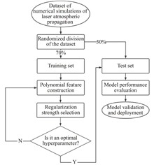
ObjectiveLaser atmospheric propagation is influenced by combined effects including turbulence, thermal blooming, atmospheric inhomogeneity, and other perturbations. Key beam quality metrics—such as target spot expansion ratio, spot radius growth, centroid displacement, and encircled energy ratio—quantify beam distortion and attenuation during atmospheric propagation, enabling systematic evaluation of laser propagation performance. Existing models fall into three categories: wave-optics models, empirical scaling-law models, and statistical analysis models. Wave-optics models provide high precision but suffer from prohibitive computational complexity for real-time applications. Empirical models simplify calculations but fail under extreme conditions (e.g., strong turbulence or thermal blooming). Statistical models enable rapid predictions but produce ensemble-averaged results insensitive to transient/local variations, require stringent data quality, and lack interpretability. This study introduces a Lasso regression-based framework to address these limitations, achieving real-time capability, high accuracy, and interpretability for laser atmospheric propagation assessment.MethodsFigure 1 outlines the Lasso regression modeling workflow (Fig.1). Simulation data were generated using a four-dimensional high-energy laser atmospheric propagation and adaptive optics compensation code developed by the Anhui Institute of Optics and Fine Mechanics, Chinese Academy of Sciences (Tab.1). The code implements a multi-phase-screen propagation model, with datasets comprising laser parameters (wavelength, power), atmospheric parameters (turbulence strength, thermal blooming distortion), and beam quality metrics. Lasso regression with L1 regularization was applied to model beam quality degradation mechanisms, automatically selecting dominant features from high-dimensional data while suppressing noise. Hyperparameters (regularization strength, convergence tolerance) were optimized via grid search (Fig.2, Tab.2).Results and DiscussionsThe Lasso regression-based model resolves critical limitations of conventional methods in real-time performance, accuracy, and feature interpretability (Tab.3). Leveraging Lasso’s feature selection mechanism, the model achieves precise predictions of beam quality metrics while maintaining computational efficiency and interpretability. Compared to traditional statistical models, it delivers superior prediction accuracy and faster computation, fulfilling real-time evaluation requirements in practical engineering scenarios. Simulation analyses demonstrate robust performance under complex atmospheric conditions, including strong turbulence and thermal blooming (Fig.3-Fig.7).ConclusionsThe proposed Lasso regression model enables rapid, accurate evaluation of laser atmospheric propagation under extreme conditions, addressing the trade-off between computational cost and physical fidelity. Its embedded feature selection mechanism aligns with laser propagation physics (e.g., turbulence-driven beam wander vs. thermal blooming-induced defocus), enhancing interpretability for field deployment. Future efforts will extend the framework to multi-wavelength/pulse regimes and hybrid machine learning architectures (e.g., physics-informed neural networks) for improved generalizability.
Jul. 25, 2025Vol. 54 Issue 7 20250054 (2025)
Rui ZHANG, Shaoyou ZHU, Yuanhang WANG, Jiashan LU, Shuwei LI, Guiqiu WANG, Yafeng GUAN, and Xuhui GENG
ObjectiveUnderwater fluorescence imaging technology is extensively utilized in various fields, including environmental monitoring, marine biological research, and marine energy exploration. However, underwater fluorescence imaging often suffers from insufficient contrast and noise interference due to the absorption and scattering of light in water, as well as other complex optical environmental factors. Because of their significant impact on image quality and subsequent analysis, there is an urgent need to develop techniques for underwater image enhancement and restoration to mitigate these effects.MethodsThe underwater fluorescence imaging detector, which primarily consists of an optical detection unit, a power supply and drive unit, and a control and data processing unit (Fig.3). Compared the two fluorescence signals and the two signal-to-noise ratios (SNR) of images of which the results were calculated with and without calibration serves to evaluate the effectiveness of the calibration method (Fig.5). The detection limit of the device was also tested to evaluate its performance in aquatic environments (Fig.6).Results and DiscussionsThe fluorescence signal intensity distribution becomes more uniform and the noise is significantly reduced after correction (Fig.7). The SNR of the image is also improved at various exposure times (Fig.8). In the underwater test, compared with the uncorrected fluorescence image of the Rhodamine B (RhB) solution, the fluorescence signal in the corrected image has been enhanced. Additionally, the contrast between the target and the background is significantly improved (Fig.9). The fluorescence signal diagram clearly illustrates a gradient distribution after correction (Fig.10). The underwater fluorescence imaging device developed in this work gained good performance with a quantification range from 130 µg/L to 910 µg/L and a detection limit low to 40 µg/L (Fig.11).ConclusionsThe experimental results show that the image correction method based on standardized coefficients not only effectively eliminates the fluorescence variations caused by the uneven intensity of excitation light, but also reduces the noise generated by the attenuation of light in the water, which in turn improves the images’ SNR. In the underwater test, the fluorescence signal of the corrected RhB solution was enhanced, the contrast was improved, and the fluorescence signal images could be reflected the concentration change. The fluorescence imaging device gained a detection limit of 40 µg/L and a quantification range of 130-910 µg/L, providing high-quality images for underwater environmental monitoring and biological research. In the subsequent research, the signal processing algorithm can be further optimized by an artificial intelligence training set, which in turn reduces the detection limit of the device and widens its linear range. By optimizing the correction algorithm, the detector is expected to be widely used in underwater imaging scenarios.
Jul. 25, 2025Vol. 54 Issue 7 20250079 (2025)
Jun YANG, Biao ZHANG, Chuanlong XU, Yuxi LI, and Qianwen WANG
ObjectiveEffective monitoring approaches for carbon dioxide (CO2) have become critical as the impact of increasing atmospheric CO2 concentration on the global climate system intensifies. Satellite remote sensing technology is the prevailing method for CO2 monitoring, and the key to successful retrieval lies in constructing forward models. Traditional forward modeling software, although capable of simulating atmospheric radiative transfer processes, suffers from limitations such as low resolution, poor computational efficiency, the neglect of scattering effects, and the inability to integrate real-time measurement data into simulations. To address these issues, this study employs the Line-By-Line (LBL) calculation method and Mie theory to calculate the spectral properties of various atmospheric components, selecting ideal bands for CO2 retrieval. Furthermore, a forward model for CO2 radiative transfer was developed based on the Discrete Ordinate Radiative Transfer (DISORT) method. The forward model accounts for multiple scattering, achieves high resolution, and is capable of integrating real-time environmental observation data into radiative transfer simulations. To address challenges such as the uncertainty of boundary conditions, physical parameters, and the unknown sensitivity of environmental factors, the model was used to analyze the impact of different environmental parameters on the spectral radiance of CO2-sensitive bands. These findings provide a theoretical basis for the development of atmospheric CO2 concentration retrieval algorithms, the selection of environmentally sensitive parameters, and the analysis of retrieval errors.MethodsAccurate gas absorption coefficients in the atmosphere are first calculated using the LBL method, followed by the computation of aerosol spectral property parameters via Mie theory. High-resolution solar spectra, underlying surface types, and atmospheric models are selected, with their results incorporated into the atmospheric radiative transfer equation. The equation is then solved using the DISORT method to obtain radiance results under arbitrary solar zenith and azimuth angles. The forward simulation results are convolved with the instrument response function to produce the final forward model outputs. After identifying CO2-sensitive spectral bands, the simulated results of the model are compared with GOSAT-2 satellite observations to validate its accuracy. Finally, the model is used to analyze the impact of environmental parameters, such as surface types, solar zenith angles, aerosol types, and Aerosol Optical Depth (AOD), on the spectral radiance within CO2-sensitive bands.Results and DiscussionsThe results indicate that CO2 in the 6300–6400 cm-1 band is minimally affected by other gases, with moderate absorption, making it highly suitable for CO2 retrieval. The normalized simulation results of the model within this band exhibit a consistent trend with the wavelength-dependent variation trend of the normalized detection results from the GOSAT-2 satellite L1B product (Fig.5), demonstrating the validity of the model. Sensitivity analysis reveals that an increase in surface albedo results in a corresponding rise in reflected radiance, thereby enhancing radiance as surface albedo varies across different surface types (Fig.6). When the surface albedo difference reaches 0.14, the difference in the average rate of relative radiance change is 123.29% (Tab.2). As the solar zenith angle increases, the optical path length grows, resulting in a decay in radiance (Fig.7). The relative radiance change exhibits bimodal characteristics (Fig.8). Aerosols, due to their varying compositions, significantly impact radiance. Urban aerosols, which include strongly absorbing components, cause substantial radiance attenuation (Fig.9), with the average relative radiance change reaching -37.66% (Tab.3). An increase in AOD leads to distinct radiance outcomes for different aerosol types (Fig.10). Urban aerosols show high sensitivity to radiance changes, with radiance rapidly decreasing as AOD increases. In contrast, maritime aerosols, characterized by strong scattering properties, result in a slight enhancement of radiance. The average rate of relative radiance change for maritime and rural aerosols remains within ±5% (Fig.11).ConclusionsA high-resolution forward model was developed to simulate the spectral radiance of CO2-sensitive bands, incorporating scattering effects and real-time environmental observation data. The results demonstrate that the selection of environmental parameters has a significant impact on forward modeling in the regional atmospheric CO2 retrieval based on satellite data. During the retrieval process, it is recommended to use surface albedo data derived from MODIS satellite observations that are spatiotemporally matched with carbon-monitoring satellites. Additionally, high signal-to-noise ratio observations with smaller zenith angles should be utilized to achieve more accurate retrievals. Moreover, the multiple scattering and absorption effects caused by aerosols cannot be ignored, particularly when retrieving atmospheric CO2 concentrations over urban areas. To minimize uncertainties caused by aerosols, prioritizing data with lower AOD is recommended. These findings provide a theoretical foundation and model basis for the development of atmospheric CO2 retrieval algorithms, the selection of environmentally sensitive parameters, and the analysis of retrieval errors.
Jul. 25, 2025Vol. 54 Issue 7 20250096 (2025)
Guobin LI, Taiwei ZHANG, Kun HU, Ao YANG, Yiping XIA, Xueming LI, Libin TANG, Peizhi YANG, Shengdi CHEN, Li YANG, and Yan ZHANG
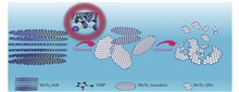
ObjectiveMolybdenum telluride (MoTe2), a transition metal dichalcogenide, possesses a narrow band gap (0.9 eV) and high electron mobility, demonstrating good application prospects in infrared optoelectronics. MoTe2 is a two-dimensional layered crystal structure combined by van der Waals forces. It is a reliable method to prepare MoTe2 quantum dots and nanosheets by liquid phase exfoliation. The kinds of solvent used in the liquid phase exfoliation method play an important role in the preparation process. However, in the related reports, studies about the effect of solvents on the exfoliation effect are rare. Therefore, it is significant to explore the best solvent of liquid phase exfoliation for the preparation of MoTe2 quantum dots.MethodsSix kinds of different solvents (1-methyl-2-pyrrolidone, 1-vinyl-2-pyrrolidone, acetone, ethanol, dimethylformamide, isopropanol) were added to MoTe2 powder by ultrasonic-assisted liquid phase exfoliation method. The mixed solution was sonicated at 210 W ultrasonic power for 6 h, centrifuged at 3000 r/min for 10 minutes, and the supernatant was taken for comparison. The size and morphology of the six samples were observed by transmission electron microscopy. The absorbance of the quantum dot solution was measured by a UV-Vis-NIR absorption spectrometer, and the turbidity of the quantum dot solution was measured by a turbidity meter. The suitable exfoliation solvent for MoTe2 quantum dots was determined using Hansen solubility theory.Results and DiscussionsThe results of transmission electron microscopy (Fig.2) show that the quantum dots prepared by 1-vinyl-2-pyrrolidone solution have the smallest size and the most uniform particle size. From the data of FTIR spectra and XRD patterns (Fig.3), it is known that the composition of quantum dots does not change during the ultrasonic process. The Hansen parameter diagram (Fig.6) shows that 1-vinyl-2-pyrrolidone with the smallest Ra value becomes a more suitable exfoliation solvent in theory. Combined with the statistical data and calculation results of (Tab.1) and (Tab.2), it is confirmed that 1-vinyl-2-pyrrolidone is indeed the suitable exfoliation solvent for MoTe2.ConclusionsBy comparing the liquid phase exfoliation effect of six kinds of solvents for MoTe2, it was found that the choice of solvent directly affects the liquid phase exfoliation effect. Combined with the calculation results of Hansen solubility theory and the experimental results of turbidity method, it was concluded that 1-vinyl-2-pyrrolidone solvent was more suitable for liquid phase exfoliation of MoTe2.
Jul. 25, 2025Vol. 54 Issue 7 20240377 (2025)
Wen WANG, Yang SI, Yimin LI, Haipeng WANG, Chaowei YANG, Yanzhen LIU, Rutong WANG, Guiqin ZHAO, Xiangqian WANG, Linwei SONG, and Xiongjun LI
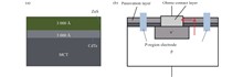
Objective With the continuous development of mercury cadmium telluride (HgCdTe) infrared detectors, the operational wavelength of HgCdTe has progressively shifted from mid-wave to long-wave and very long-wave, imposing higher demands on device performance such as resolution, reliability, and sensitivity. As a narrow-bandgap semiconductor device, the surface of HgCdTe infrared focal plane detector chips is susceptible to fixed charges introduced by contamination or dangling bonds, which can cause band bending of one to several bandgap magnitudes. This leads to accumulation, depletion, or inversion at the surface of HgCdTe materials, thereby increasing the surface leakage current and severely degrading device performance. Additionally, the high activity of Hg atoms in the material and the relatively low bond energy of Te-Hg bonds make Hg prone to escape, resulting in a Te-rich surface that further impacts device performance. Therefore, surface passivation is a critical step in the fabrication process of HgCdTe photovoltaic infrared focal plane detectors.Methods N-type Hg1-xCdxTe thin films were grown on cadmium zinc telluride (CdZnTe) substrates using horizontal liquid phase epitaxy. A CdTe/ZnS passivation layer was deposited via magnetron sputtering, and the schematic structure is shown in Fig.1(a). After passivation film growth, the samples were diced using a wafer saw and subjected to interdiffusion annealing under different conditions. The entire annealing process was carried out in a nitrogen atmosphere, with temperature fluctuations kept within 4 ℃ after reaching the set temperature. After annealing, the samples were cooled to room temperature over 25–35 minutes. Subsequently, dry etching was performed to open contact holes, and metal electrodes were deposited to complete the fabrication of long-wave HgCdTe devices, as illustrated in Fig.1(b).Results and Discussions Based on the improved three-stage annealing process described above, it was applied to long-wave mercury cadmium telluride unit devices. Figure 8 presents the corresponding I-V test results. The long-wave devices fabricated using the high-temperature three-stage annealing process exhibit superior performance under reverse bias voltage compared to those prepared by the traditional annealing process, particularly in the region where the reverse bias voltage exceeds 150 mV. This phenomenon is primarily attributed to the high-temperature three-stage annealing process, which enables the formation of higher-quality passivation layer crystal structures and thicker high-composition transition layers. As a result, the fixed charge density and defect state density on the material surface are significantly reduced, ultimately leading to a decrease in the leakage current of the long-wave devices.Conclusions The quality of the surface passivation film grown by magnetron sputtering and the thickness of the high-composition transition layer have a decisive impact on the performance of mercury cadmium telluride (HgCdTe) infrared devices. To address the conflict between the thickness of the high-composition transition layer and the minority carrier lifetime of the material in traditional annealing processes, we innovatively proposed a three-stage annealing process. This process not only successfully prepared high-quality CdTe passivation films and achieved a thicker high-composition transition layer but also significantly improved the minority carrier lifetime of the material, thereby achieving synergistic optimization of passivation film quality, high-composition transition layer thickness, and material minority carrier lifetime. Experimental results show that long-wave infrared devices fabricated using the three-stage annealing process exhibit significantly improved reverse leakage current levels in I-V characteristic tests, especially under high reverse bias voltages, where the leakage current is markedly reduced, leading to enhanced device performance. In the future, we will further optimize the annealing process parameters, explore more refined temperature and time control strategies, and extend the application of this process to long-wave HgCdTe infrared focal plane devices to verify its universality and scalability.
Jul. 25, 2025Vol. 54 Issue 7 20250015 (2025)
Zhiyuan XI, Hailiang SHI, Jiasheng CAO, Xiongwei SUN, Xianhua WANG, and Jile WANG
ObjectiveThermal protection for infrared cameras is critical for maintaining their stability under complex operating conditions, such as high temperatures and high humidity. The elevated temperatures and humidity during the drying process pose significant challenges to the camera’s performance and lifespan, potentially causing deformation of the imaging window, damage to electronic components, and a loss of temperature measurement accuracy. To address these issues effectively, a thermal shield that combines thermal insulation with active cooling is essential to maintain the camera’s operating temperature within its acceptable range (10 ℃ to 50 ℃). This thermal protection device must provide efficient heat dissipation, reliable sealing, and compact design. However, conventional thermal protection methods relying solely on insulation or basic cooling are insufficient to meet the demands of such complex conditions. Therefore, this study proposes a thermal protection device for infrared thermal imager that integrates passive insulation with active cooling, enabling adaptation to high-temperature, high-humidity environments while optimizing the camera’s temperature measurement performance and operational stability.MethodsA thermal protection structure for an infrared thermal imager is proposed (Fig.3). The design integrates passive thermal insulation using a PTFE housing and active heat transfer optimization with a diffuser installed at the cooling air inlet (Fig.4). Numerical simulations were performed to determine the optimal structural parameters of the diffuser (Fig.5). The flow and heat transfer processes within the structure were analyzed using computational fluid dynamics (CFD), with the Realizable k-ε turbulence model selected as the computational approach. Grid-independence validation (Fig.6) was conducted to ensure that the numerical simulation results were unaffected by the grid density. In order to verify the validity of the numerical simulation results, experimental tests were carried out within the high temperature drying process section (Fig.14).Results and DiscussionsThe guide vane angle was increased from 35° to 55°, significantly improving convective heat transfer efficiency and optimizing temperature distribution (Fig.7). The cooling effect was optimal at 55°, where the average temperature of the thermal imaging camera was 36.55 ℃, and the maximum temperature was 36.7 ℃ (Fig.8). When the horizontal diffusion circle diameter D1=40 mm, the average temperature of the infrared thermal imager was further reduced to a minimum of 33.65 ℃ (Fig.10), and the convective heat transfer coefficient reached a maximum value of 78.07 W·m-2·K-1 (Table 5), achieving optimal airflow distribution and temperature uniformity. Under fixed guide vane angle and diffusion circle diameter conditions, the guide vane length L=10 mm, resulted in the lowest infrared thermal imager temperatures, with an average temperature of 33.65 ℃ and a maximum temperature of 33.75 ℃ (Fig.12). At this length, the convective heat transfer coefficient also reached its maximum value of 78.07 W·m-2·K-1 (Tab. 6), indicating optimal airflow disturbance and heat transfer efficiency. However, excessive guide vane length reduced cooling performance and caused a temperature rebound. The temperature of the cooling air varies with seasonal weather, requiring a higher flow rate to enhance convective heat transfer in hot conditions. At an air inlet temperature of 38 ℃, increasing the flow rate from 40 m/s to 140 m/s reduced the average temperature of the camera from nearly 50 ℃ to 42.35 ℃ (Fig.13), meeting its operational requirements. The influence of the thermal gradient on heat conduction was analyzed, with the calculated results presented in Tab.7. The maximum deformation observed was 0.11 mm, and the peak thermal stress reached 5.52 MPa, both within acceptable limits. Numerical simulations were conducted under the same boundary conditions as the experiments, and the results from both approaches were compared. Figure 15 illustrates the comparative analysis between experimental data and numerical simulation outcomes under varying air inlet temperatures. The findings indicate a high degree of correlation between the numerical simulations and experimental measurements, with the maximum relative error for peak temperatures at measurement points being 5.72%, and for average temperatures, 5.92%.ConclusionsA forced convection heat transfer protection structure was designed by integrating passive heat insulation and active convection technologies. The passive design utilizes low thermal conductivity materials to form a shell structure, minimizing heat transfer in high-temperature environments. For active cooling, high-pressure gas is introduced as a cooling source, with a circular diffuser and optimized air inlet structure enhancing convective heat transfer efficiency. Both numerical simulations and experimental tests confirm that the proposed structure can reliably protect infrared thermal imager in ambient temperatures up to 130 °C. The optimized design achieves uniform cooling gas distribution, lowering the maximum camera temperature from 42.6 ℃ to 33.75 ℃—a 20.78% reduction. Under extreme room temperatures of 38 ℃, increasing the air inlet velocity to 140 m/s reduces the camera temperature to 42.35 ℃, meeting operational requirements. This study provides a valuable reference for addressing thermal protection challenges of optical instruments in industrial high-temperature scenarios. The experimental validation ultimately confirmed the effectiveness of the thermal protection structure, with the experimental results demonstrating excellent agreement with the numerical simulation outcomes.
Jul. 25, 2025Vol. 54 Issue 7 20250026 (2025)
Shaohua CHEN, Shida ZHANG, Jiaojiao REN, Jian GU, and Lijuan LI
Objective During actual use of the black high-emissivity coating on the surface of porous materials, micro-cracks on the surface of micron scale are generated due to thermal stress. In order to facilitate the subsequent development of the evolution and expansion laws of crack defects under thermal stress, low-contrast coating surface crack morphology research on visual inspection technology. A detection method that combines optical optimization and deep learning is proposed. By designing a light source to stimulate a monocular vision system, first optimizing the illumination method and incident angle parameters from the perspective of system design to enhance the local contrast of collected crack images. It proposes an algorithm to adapt to low-contrast image crack contrast enhancement. In turn, an improved U-Net network is built to improve the ability to extract low-contrast crack features by embedding attention modules, deep hyperparametric convolution and activation functions. Experimental results show that the local contrast of the acquired images is the highest when the incident light is 30° in the high illumination mode. After preprocessing, the image contrast is increased from 10.507 to 42.662, which effectively reduces the influence of background noise on crack information when the image is low contrast, and can better highlight the morphological characteristics of cracks. The Dice coefficient, SSIM index and accuracy Acc of the improved network reached 0.862, 0.892, and 0.901 respectively in terms of crack segmentation performance indicators. The detection rate of cracks with widths greater than 9.6 μm reached more than 90%, and the crack shape and direction were clearly recognizable.Methods In order to identify the shape and direction of microcracks on low-contrast images and define the minimum detection width, this study built a monocular vision acquisition platform to collect high-quality images starting from the lighting method and light incidence angle (Fig.1), so as to improve the contrast between microcracks and the substrate background, preprocess the image to reduce the influence of the background on crack information, and improve the contrast between cracks and background (Fig.4). Through the improved U-Net network model (Fig.11), an attention mechanism is added at the junction of down-sampling and up-sampling jumps to avoid the model being affected by image noise, improve the extraction ability of key features, and use deep hyperparametric convolution to increase the number of convolution kernels., more features can be extracted, thereby improving the model's representation ability and segmentation accuracy to complete the detection of cracks on the coating surface, and realizing crack segmentation.Results and Discussions Based on the design of the vision system in this research, high-quality images were obtained. The contrast of the original image was 10.507, and after pre-processing, the contrast was increased to 42.662, which was improved by 4 times, make the difference between the crack information and the background area in the image more obvious. Through this algorithm Att-Do-U-net combines the attention mechanism with the deep hyperparametric convolution structure, it ultimately performs the best among various indicators. The highest values were reached in terms of Dice coefficient of 0.862, SSIM index of 0.892 and accuracy of 0.901. In addition, in terms of segmentation results, the segmented crack information has a more complete vein structure, and also has a good segmentation effect on small branches of cracks (Fig.16). The lines are continuous and smooth on the segmentation results, which is better than the results of broken lines, breakpoints, etc. in other results. The cracks that cannot be detected are discussed (Fig.18). Between 4.8 and 9.6 μm, the crack detection rate is less than 25%, while between 9.6 and 14.4 μm, the crack detection rate is as high as more than 90%. For crack widths above 14.4 μm, the detection rate reaches 100%, so the minimum width of detectable cracks is defined as 9.6 μm.Conclusions In this paper, a light source excited monocular vision system is constructed. By optimizing lighting methods and image preprocessing algorithms, combined with improving U-Net network, accurate detection of low-contrast micro-cracks is achieved. The pretreatment method in this paper can reduce the interference of noise and obtain complete crack information. The segmentation effect of low-contrast crack images based on the improved U-net network is better than that of the original U-shaped network. The crack segmentation is more complete. The boundary of crack morphology characteristics on the result is smoother. The average SSIM reaches 0.892, and the Dice coefficient reaches 0.862. A crack width of 9.6 μm can be recognized in terms of crack width definition. The current method has limitations for crack detection less than 10 μm. In the future, super-resolution reconstruction technology can be introduced to recover the crack skeleton from low-resolution crack images to achieve lower-width detection.
Jul. 25, 2025Vol. 54 Issue 7 20250035 (2025)
Zheng WANG, Qinghua LIANG, Haocheng XIANG, Tian LU, and Ruijun DING
ObjectiveWith the development of infrared focal plane detector applications, there is an increasing demand for high-frame-frequency imaging, such as the detection and tracking of high-speed small targets, and the tracking and imaging of unmanned aircraft swarms in complex backgrounds, and other fields. The infrared dynamic vision sensor is a bionic sensor different from the traditional infrared sensor, which integrates the photocurrent at a fixed frame rate to form a grayscale image, whereas the infrared dynamic vision sensor asynchronously measures the luminance change of each pixel and outputs the position, time, polarity, etc. of the area of the luminance change in the form of an event stream, which removes the background interference and retains the information of the moving object only, greatly reducing the data Redundancy and lower transmission pressure. Compared with the traditional infrared focal plane readout circuit, the infrared dynamic vision sensor readout circuit has the advantages of high temporal resolution, high dynamic range and low power consumption. Therefore, in this paper, a digital processing circuit based on infrared event detector devices and its visualization method are designed.MethodsThe paper adopts Round Robin arbitration principle in digital circuit design, which replaces the arbitration tree and reduces the arbitration delay (Fig.4). At the same time, it adopts only row arbitration, together with the output of the whole row information through the compression algorithm, which reduces the delay brought by the column arbitration and the redundancy of the time-stamped information (Fig.5). Two RAM IP cores are used to accumulate the event data over time, enabling writing and reading, and ultimately transmission via the HDMI protocol (Fig.7).Results and DiscussionsUsing the robin arbitration algorithm, the arbitration result can be output in one clock with a delay of 1 clock, which is a significant improvement compared to the arbitration tree structure with a delay of 2-9 clocks. Using only line arbitration with the whole line of information through the compression algorithm output, the equivalent frame rate FR = 1085 Hz, data throughput EPS = 0.36 G, the results are comparable to the visible light band product parameters (Tab.1).ConclusionsFacing the application requirements of infrared focal plane high frame rate readout, a digital processing method for differential infrared dynamic vision sensors is proposed in this paper, which adopts polling arbitration algorithm instead of arbitration tree structure to reduce the impact of arbitration delay; at the same time, it adopts only row arbitration together with the data compression output to reduce the uncertainty and arbitration delay caused by column arbitration. The design is verified using Xilinx FPGA development board, and the corresponding visualization method is proposed. In the visualization process, the 40 bit timestamp information is not used, which can be used for subsequent digital image processing of the event stream. It lays a technical foundation for the development, testing and data processing of the subsequent infrared band dynamic vision sensors.
Jul. 25, 2025Vol. 54 Issue 7 20250077 (2025)
Xiying WANG, Donghang JIANG, Zeyu ZHU, Baohai GAO, Hong QI, and Yatao REN
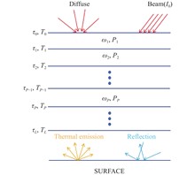
Objective The solution for the infrared radiation characteristics of the tail flame gas exhibits stronger spectral selectivity and volumetric participation compared to the infrared radiation from the skin. The absorption of asymmetric polyatomic gas molecules demonstrates significant spectral selectivity. Consequently, prior to analyzing the infrared radiation characteristics of the tail flame, it is essential to determine the fundamental physical properties of the gas medium, such as the spectral absorption coefficient, spectral scattering coefficient, and spectral transmittance. Typically, the tail flame plume of an aeroengine consists of H2O, CO2, CO, and common atmospheric molecules. Since the infrared radiation of symmetric diatomic molecules can be disregarded, only the absorption and emission of H2O, CO2, and CO molecules need to be considered. In addition to these molecules, the infrared radiation characteristics of the aircraft are also influenced by the high-temperature walls of the exhaust system. In this case, both the emitted radiation from the high-temperature wall and its diffuse reflection characteristics must be considered. Calculating the spectral physical properties of the tail flame medium represents the primary challenge in determining its infrared radiation characteristics.MethodsA solution method for the radiation transfer equation that combines the apparent ray method and the reverse Monte Carlo method has been proposed. The combined method has the advantages of both methods and can quickly solve the radiation transfer equation for absorption and scattering media. Combined with the statistical narrow-band k-distribution model, the influence of different gas basic physical property libraries on the infrared radiation characteristics of the exhaust system was calculated and analyzed. Considering the existence of multiple versions of HITRAN/HITEMP database, systematic comparison was made between HITRAN database and HITEMP database for solving basic physical properties of gas radiation (Fig.3), and the influence of database version on solving absorption coefficient and radiation intensity was analyzed.Results and Discussions The mean absorption coefficient and spectral radiation intensity of single molecule Planck are calculated by using the database, and the absolute errors of the calculated results of each physical property library are calculated relative to HITRAN2020 (Fig.5-7). The results show that the absolute errors of CO2 molecules exist near three absorption peaks in the bands of 2.7 μm, 4.3 μm and 8-14 μm. The absolute error of CO molecule almost only exists around 2100 cm-1 wave number. The maximum absolute error of the absorption coefficient of H2O molecules at a wavenumber of 150 cm-1 is 0.024 (Fig.11-13). This is because the wavenumber of 150 cm-1 is far from the emission center of the Planck function. Finally, the accuracy of the proposed method was evaluated based on the experimental results (Fig.17-20).ConclusionsConsidering the existence of multiple versions of the HITRAN/HITEMP databases, a systematic comparison was performed among various versions of the HITRAN and HITEMP databases to address the fundamental physical properties of gas radiation. The impact of database versions on the calculation of absorption coefficients and radiation intensity was thoroughly analyzed. Given that the HITRAN database lacks spectral line information for CO molecules in the 8-14 μm band, if the partial pressure of CO in the high-temperature gas under consideration is relatively significant or the calculation results are highly dependent on CO, it is recommended to use the HITEMP database for calculations. The absolute errors of Planck-mean absorption coefficients and spectral radiation intensities of single molecules calculated using the HITRAN2008, HITRAN2012, and HITRAN2016 databases relative to HITRAN2020 were evaluated and compared. Results demonstrate that for CO2 molecules, absolute errors occur near the three absorption peaks in the 2.7 μm, 4.3 μm, and 8-14 μm bands; for CO molecules, absolute errors are predominantly observed near the wavenumber of 2100 cm-1; and the spectral line information of H2O molecules has undergone substantial changes, affecting both the relative magnitude of absorption coefficient values and their distribution across different wavenumber positions. Considering that the infrared radiation characteristics of the exhaust system are influenced by both absorbent gases and diffuse-reflecting solid boundaries, a novel method for solving the RTE was developed by integrating the apparent ray method with the reverse Monte Carlo method. The performance of this method was assessed in an experimental setting. Results confirm that the proposed method can more accurately predict and analyze light transmission issues in complex environments.
Jul. 25, 2025Vol. 54 Issue 7 20250110 (2025)
Yu LIU, Chenghao JIANG, Ye YUAN, Tianpeng XIE, Buyun PING, and Jingguo ZHU
ObjectiveLidar detects targets by actively emitting and receiving laser signals, and obtains information such as the target's distance, speed, and direction from the reflected echo. FMCW lidar is a ranging technology based on frequency modulated continuous wave signals, combining the advantages of frequency modulated continuous wave ranging and laser detection. This technology transmits a frequency modulated continuous wave to the target, mixes the signal light with the intrinsic light, and uses the beat frequency signal generated by laser interference to calculate the distance and speed of the target, thereby achieving high-precision distance and speed measurement. It has the characteristics of integrated distance and speed measurement and strong anti-interference ability. However, during laser transmission, depolarization effects may occur due to atmospheric turbulence or reflection from the target surface, resulting in polarization mismatch between the echo light and the intrinsic light. This polarization mismatch can significantly reduce the heterodyne efficiency, signal-to-noise ratio, maximum detection distance, and detection accuracy of the system. Therefore, in order to achieve high-precision long-distance detection, research on the polarization characteristics of FMCW lidar echoes has important academic significance and application value.MethodsIn actual detection of FMCW laser radar, the polarization matching degree between signal light and intrinsic light directly determines the heterodyne efficiency of coherent detection, which in turn affects the signal-to-noise ratio, detection distance and accuracy of the FMCW laser radar system. Since the polarization state of the intrinsic light remains stable when it is transmitted in the polarization-maintaining fiber, and the polarization state of the signal light changes due to the scattering of the detection target surface when it is received by the optical system after undergoing a complex atmospheric propagation process. Therefore, it is particularly important to analyze the polarization characteristics of the echo in order to better understand its impact on the performance of the FMCW laser radar system. Based on the optimization and improvement of the traditional FMCW laser radar detection principle, a new detection system based on polarization orthogonal demodulation is proposed. A 1/4 wave plate is added to the incident end of the signal light, and the different polarization states of the signal light are simulated by changing the fast axis angle of the wave plate. The intensity of the balanced detector output signal is analyzed and verified.Results and DiscussionsIn view of the polarization mismatch between the echo light and the intrinsic light caused by the change of polarization state caused by the surface scattering of the detection target, this paper analyzes and studies the detection performance of FMCW laser radar based on polarization orthogonal demodulation from the perspective of target detection and recognition, effectively solving the problems of weakened detection capability and limited detection distance caused by polarization mismatch. The experimental results show that under the same test environment, compared with the typical detection method, the side mode suppression ratio of the six detection targets (reflector, quadcopter UAV, bird feather, green luo, marble, plastic bag) is improved by 11.85%, 11.98%, 13.46%, 15.39%, 17.12%, and 18.29% respectively. Further experiments show that by adjusting the wave plate angle (22.5°, 45°, 60°), when the wave plate angle is 45°, the ranging standard deviation reaches the minimum value of 0.012 m, and the side mode suppression ratio can be increased to 16.931 dB. Through the study of the echo polarization state, further theoretical support is provided for the application of FMCW laser radar in target recognition.ConclusionsThis article combines polarization information with FMCW laser radar technology to provide theoretical basis for the polarization characteristics of echoes, expand their applications in military, autonomous driving, and industrial detection fields, improve target recognition, low reflectivity target detection, and environmental perception capabilities, solve the recognition limitations of traditional laser radar in complex environments, and provide theoretical support for high-precision target recognition and system optimization design.
Jul. 25, 2025Vol. 54 Issue 7 20250044 (2025)
Xiaodong YAN, Jinbao SU, Bo WU, Ying LIU, Jun DENG, and Yiyang XIE
ObjectiveThe distributed Bragg reflector (DBR) is a crucial component of vertical-cavity surface-emitting laser (VCSEL), relying on the multilayer stacking of high-refractive-index and low-refractive-index materials to achieve high reflectivity through interference superposition of reflected light. The DBR structure of traditional VCSELs typically uses the AlGaAs material system, however, due to the small difference in refractive indices between materials with different Al compositions, the reflection bandwidth of the DBR structure is narrow, which affects the mode stability of VCSEL. The critical absorption wavelength of the AlGaAs material system is relatively long, resulting in some absorption losses. Moreover, the multi-layer growth process of AlGaAs DBR requires extremely high precision, increasing manufacturing difficulty and cost. The use of metal-organic chemical vapor deposition (MOCVD) to grow DBR structures typically requires high temperatures, making it incompatible with the photolithographic lift-off process for optoelectronic devices, which is not conducive to patterned growth. Therefore, this paper investigates a DBR structure with a wide reflection bandwidth, low absorption loss in the visible and near-infrared bands, and the ability to be deposited at room temperature, which perfectly matches the fabrication process of VCSEL devices.MethodsIn this study, the reflection spectrum of the SiO2/ZnS material system DBR structure was simulated and calculated to determine the number of periods required to meet the requirements of a wide reflection bandwidth and high reflectivity at the target wavelength (Fig.3). The thickness tolerances of the two materials in the DBR structure were also calculated. The process flow for the fabrication of the inner cavity contact VCSEL device has been designed (Fig.5), and magnetron sputtering was used to deposit the DBR structure on VCSEL devices, as well as on quartz glass and GaAs substrates. The reflection spectrum of the deposited DBR structure was measured using a micro-area spectroscopic measurement system. Additionally, the P-I-V characteristics and spectral properties of the devices were tested using a laser testing system.Results and DiscussionsUsing a micro-area spectroscopic measurement system, the reflection spectra of an 8-period DBR structure deposited on quartz glass and GaAs substrates were obtained. The designed center wavelength was 850 nm, and the reflection bandwidth with reflectivity exceeding 99% reached 209 nm (Fig.6). The VCSEL device with an oxide aperture of 8 μm exhibited a threshold current of 0.5 mA and achieved a peak output power of 1.55 mW at an injection current of 3.45 mA (Fig.9). The central wavelength in the spectrum was 843 nm, and the far-field divergence angle was less than 20.6°(Fig.10). The devices with the DBR center wavelength offset by 50 nm also achieved stable lasing, with no significant differences in P-I-V characteristics and spectral properties compared to devices matching the designed center wavelength. These results indicate that precise matching of the center wavelength to the design parameters is not necessary, further validating the broadband advantage of this DBR structure.ConclusionsThis study investigated vertical-cavity surface-emitting laser (VCSEL) with broadband mirrors based on the SiO2/ZnS material system. A broadband DBR structure using the SiO2/ZnS material system was designed through simulations, and the results showed that the DBR structure achieved a high reflectivity exceeding 99% within a reflection bandwidth of 209 nm, meeting the requirements for broadband VCSEL applications. VCSEL devices with the broadband DBR were fabricated and characterized, exhibiting excellent P-I-V performance at room temperature, with a threshold current of 0.5 mA and a peak output power of 1.55 mW. Additionally, the broadband DBR structure demonstrated a high tolerance to center wavelength variations, maintaining stable VCSEL output over a wide range of wavelength shifts. This characteristic significantly reduces the precision requirements for film deposition during fabrication, providing feasibility for large-scale, low-cost VCSEL production.
Jul. 25, 2025Vol. 54 Issue 7 20250059 (2025)
Yan LIANG, Ning AN, Xingwei HAN, Zhipeng LIANG, Bin GUAN, Haitao ZHANG, and Chengzhi LIU
ObjectiveSatellite Laser Ranging (SLR) serves as a high-precision space geodetic technique, significantly contributing to the determination of the origin and scale factor of the International Terrestrial Reference Frame (ITRF). However, system delay in SLR is one of the main factors affecting ranging accuracy, and traditional ground target measurement method has limitations in real-time performance. Traditional ground target measurements are carried out separately before and after satellite observation or at fixed time intervals, such as every 60 minutes. This approach has limitations in capturing the real-time changes in system delay, especially when system delay varies dynamically with time, environment, and operational status. For example, changes in environmental temperature and thermal drift of electronic equipment can cause dynamic changes in system delay, which cannot be promptly reflected by fixed-time interval measurements, affecting ranging accuracy and the real-time performance and reliability of observational data. To enhance SLR data precision, a method of obtaining SLR system delay values using the geodetic satellite LAGEOS-1 as a satellite target has been proposed and verified by the SLR system at Changchun Observatory. By adopting a strategy of alternating measurements between the satellite target and the observation target, the real-time performance of the measurement method is enhanced. Finally, the SLR observation data are improved using the SLR system delay values, offering support to enhance SLR ranging precision.MethodsThe researchers selected LAGEOS-1 as the satellite target due to its strong orbital stability, broad motion coverage, and even data distribution (Fig.2). The study selected LAGEOS-1 as the satellite target due to its strong orbital stability, broad motion coverage, and even data distribution. It established a SLR range model, using precise ephemerides as the accurate result, and applied the least square method to the ranging residuals to obtain the system delay. Three satellites with different orbital altitudes, LAGEOS-2, AJISAI, and ETALON-1, were selected to validate the results.Results and DiscussionsThe precision of the ranging data corrected by the satellite target has improved, with enhancements ranging from 13.5 mm to 100.7 mm, averaging an improvement of 50.2%. The range bias of the observational targets has also decreased, with reductions between 13.7 mm and 142.1 mm, and an average improvement rate of 48.6% (Tab.5). Specifically, the RMS of the ranging residuals for the LAGEOS-2 satellite decreased by 57.2 mm and 14.9 mm, with relative change rates of 72.4% and 70.7%, respectively (Fig.4). For the AJISAI satellite, the RMS of the ranging residuals decreased by 70.2 mm, 44 mm, 13.5 mm, and 32.4 mm, with relative change rates of 31.9%, 74.2%, 12.8%, and 19.7%, respectively (Fig.5). The ETALON-1 satellite showed reductions in the RMS of the ranging residuals by 67.3 mm, 100.7 mm, 32.3 mm, 54.4 mm, and 65.3 mm, with relative change rates of 57.8%, 62.8%, 58.4%, 46.1%, and 45.8%, respectively (Fig.6).Compared to the AJISAI satellite, the SLR system delay values obtained by the satellite target demonstrated a better correction effect on the ETALON-1 satellite. The AJISAI satellite exhibited average improvement rates for the RMS of the ranging residuals and range bias of 34.6% and 45.8%, while the ETALON-1 satellite showed average improvement rates of 54.2% and 68.2%. The higher orbital altitude of ETALON-1, along with its lower angular velocity and slower system state changes, may contribute to the more significant correction effects observed when using LAGEOS-1 as the satellite target.ConclusionsA method for calibrating SLR system delays using the geodetic satellite LAGEOS-1 as a calibration target has been proposed. Compared to ground targets, LAGEOS-1 provides a reliable reference for system delay calibration with an observation accuracy difference of only 6 picoseconds. The effectiveness of this method was validated through alternating observations of satellites with varying orbital altitudes (LAGEOS-2, AJISAI, and ETALON-1) using the SLR system at the Changchun Observatory. The results indicate that, in the case study presented in this paper, the SLR system delay values obtained using the satellite target can enhance the precision of SLR data by 13.5 mm to 100.7 mm and reduce range biases by 13.7 mm to 142.1 mm. Notably, the calibration using the satellite target exhibits a more pronounced correction effect on the higher-orbit ETALON-1 satellite, suggesting that this method is particularly advantageous for calibrating delays when dealing with high-orbit satellites.
Jul. 25, 2025Vol. 54 Issue 7 20250088 (2025)
Jing LIU, Jun MENG, Gaoyou LIU, and Zhaojun LIU
ObjectiveThe 1.5 μm laser is located both in the near-infrared atmospheric window and in the eye-safe wavelength band, so there is a wide demand for 1.5 μm lasers in fields such as optical communication, laser ranging, and lidar. Currently, optical parametric oscillators (OPOs) based on the principle of nonlinear frequency conversion, represent a prominent approach for generating 1.5 μm lasers. KTiOAsO4 (KTA) is an ideal material for generating 1.5 μm laser output via OPO technology due to its high nonlinear coefficient, broad transmission range, and high damage threshold. However, research in this field has primarily focused on extracavity OPOs operating below 100 Hz and intracavity OPOs operating above kHz. While low repetition frequency extracavity KTA-OPOs have successfully achieved high power 1.5 μm laser output, the output power levels of high repetition frequency intracavity KTA-OPOs are generally lower due to limitations of intracavity power density. In response to the current research status and the demand for high repetition frequency and high power 1.5 μm lasers in application fields, the 10 kHz 1.5 μm laser output power is enhanced by utilizing extracavity KTA-OPO.MethodsTo obtain a pump beam with a repetition rate of 10 kHz and good beam quality, a master oscillator power amplifier (MOPA) system was constructed using LD end-pumped Nd:YVO4 crystals. The 1064 nm oscillator utilizes a BBO crystal for electro-optic Q-switching to achieve a 10 kHz laser, and three-stage amplification is carried out afterwards. In the amplifier stages, to minimize the impact of thermal effects, the first two stages employ single-end pumping, while the third stage uses dual-end pumping. Lenses are placed between each stage to ensure good mode matching between the pump and oscillation spots. During the OPO stage, a plane-plane cavity OPO is built using KTA as the nonlinear crystal to achieve type II non-critical phase matching for the generation of 1.5 μm parametric light. The optical-to-optical conversion efficiency is enhanced by optimizing the pump spot size and the oscillator cavity length (Fig.1).Results and DiscussionsThrough electro-optic Q-switching technology, the oscillator achieves a 1064 nm laser output of 1.02 W, with a repetition rate of 10 kHz and a pulse width of 7.1 ns. The beam quality factors are M2x=1.18 and M2y=1.20 (Fig.2). Using 878 nm LDs as the pump sources, the oscillator power was successfully increased to 6.26 W, 12.40 W, and 20.13 W. The corresponding beam qualities are as follows: for the first stage, M2x=1.20, M2y=1.26; for the second stage, M2x=1.32, M2y=1.26; for the third stage, M2x=1.42, M2y=1.49 (Fig.4). With a cavity length of 40 mm and a pump spot diameter of 430 μm, the KTA-OPO generates a laser with a central wavelength of 1535.8 nm and a maximum output power of 6.26 W (Fig.5). The corresponding optical-to-optical conversion efficiency is 33%, with a pulse width of 7.2 ns and a linewidth of 0.26 nm. The beam quality factors are M2x=2.75 and M2y=3.81 (Fig.6).ConclusionsA high-power 1.5 μm laser with a repetition frequency of 10 kHz has been successfully obtained using an extracavity KTA-OPO structure. To achieve high beam quality pump beam, a MOPA was constructed using LD end-pumped Nd:YVO4 crystals. By combining single-end pumping and double-end pumping in a three-stage amplification, a 1064 nm pump light with a beam quality factor better than 1.5 and a pulse repetition rate of 10 kHz was obtained, with an average power of 20.13 W. In the aspect of the KTA-OPO, the effects of cavity length and pump spot diameter on the pump threshold and conversion efficiency were comparatively studied. The pump spot parameters and resonator parameters were optimized to improve the conversion efficiency of the KTA-OPO, 1.5 μm pulsed laser with an average power of 6.26 W and a pulse width of less than 10 ns, corresponding to an optical-to-optical conversion efficiency of up to 33%. Adoption of extracavity KTA-OPO structure effectively improves the high-frequency 1.5 μm laser output power. Subsequent improvements should focus on enhancing the 1064 nm pump laser power while maintaining good beam quality. Additionally, adopting a ring cavity structure could further optimize the beam quality of the KTA-OPO. Moreover, single-frequency seed injection could be employed to narrow the output linewidth, thereby meeting practical application requirements.
Jul. 25, 2025Vol. 54 Issue 7 20250104 (2025)
Mingxin ZHANG, Xiaoya LIU, Jiacheng ZHOU, Junpeng LU, Zhenhua NI, and Junjia WANG
Significance With the growing demands of big data technologies, there is an increasing need for improved data transmission speed, bandwidth, and energy efficiency. Photons, as a medium for information transmission, possess unique advantages, such as high bandwidth, rapid transmission speeds, low power consumption, and compatibility with CMOS technology. Micro-transfer printing has become a pivotal technique for wafer-scale heterogeneous integration, enabling the co-integration of various materials or devices detached from their substrates and transferred onto silicon-based optoelectronic target substrates. This technology offers remarkable versatility and integration potential. This paper delves into recent developments in micro-transfer printing (MTP), exploring its underlying mechanisms, transfer methodologies, and applications. Additionally, it evaluates yield rates, process optimization, and equipment reliability, providing insights into the commercial viability of this technology.Progress This review discusses various auxiliary methods used in micro-transfer printing. During device transfer from a stamp onto a target substrate, the adhesion force of the stamp must be less than the interaction force between the devices and the substrate. Adhesives are commonly used to strengthen the interaction force between the devices and the substrates. The performance of integrated devices is heavily influenced by the interface contact between metal electrodes and materials. Traditional metal deposition processes often introduce defects, strain, and metal diffusion, leading to high resistance at the contact interface. Two-dimensional materials, which lack surface dangling bonds, help mitigate these issues during the transfer process. In laser-assisted non-contact transfer, the laser absorption layer absorbs energy, heating the water in the hydrogel and inducing a localized liquid-to-vapor phase transition. This phase transition causes the adhesive layer's surface to bulge, effectively eliminating interfacial adhesion forces. In recent years, micro-transfer printing has shown significant advantages in heterogeneous integration, allowing for the high-density integration of diverse photonic components, including C-band tunable lasers on SOI and SiN platforms, InGaAsP-based photodetectors, and electro-optical modulators such as thin-film lithium niobate devices. The paper also explores the future commercialization prospects of micro-transfer printing technology.Conclusions and Prospects This work provides a thorough review of heterogeneous integration techniques based on micro-transfer printing. MTP technology is crucial for the fabrication of high-performance heterogeneous photonic integrated circuits. However, its commercialization in the photonics field faces several challenges. Achieving large-scale production requires addressing key factors such as batch production yield, which depends on the yield of devices from the source wafer, the release process, the pickup process, and the printing process itself. Process optimization and device performance are critical areas that need improvement. For instance, capillary forces can cause materials to collapse or fracture, but these issues can be mitigated through vapor-phase etching processes. Additionally, the strength and number of tethers supporting the devices play a vital role in the transfer process, necessitating the design of optimized tethers to improve transfer efficiency. The reliability of transfer printing equipment is another critical consideration. As micro-transfer printing technology matures, this heterogeneous integration method has become essential for fabricating high-performance photonic integrated circuits, and overcoming these challenges will be key to its widespread commercialization.
Jul. 25, 2025Vol. 54 Issue 7 20250115 (2025)
Haoran WANG, Mingxu PIAO, Xian ZHANG, Chenxiao LI, Yichen LOU, Huitian ZOU, Yingran TONG, Junsong WANG, and Bo ZHANG
ObjectiveWith the advancement and development of science and technology, traditional optical systems are no longer able to meet the growing demand of people. Conformal optical sphere cover is an optical protective structure that highly matches the shape of the carrier, and the demand for conformal optical sphere cover is increasing with new high-tech things. However, traditional conformal optical systems require the addition of a phase plate at the rear of the system, resulting in excessive mass and high cost. In order to reduce the weight of the conformal optical system and simplify its structure, a conformal optical system without the need for additional phase plates was designed using the optical numerical joint method, effectively reducing the system weight and simplifying the system structure.MethodsWe studied a method based on optical numerical joint to eliminate the influence of aerodynamic optical effects on conformal optical systems, and investigated the restoration of overall scanning angle images based on different feature scanning angles (Fig.9). In the image restoration section, the sum of image gradients based on different feature scanning angles was studied (Tab.2), and the Richardson Lucy iterative algorithm was used to deconvolve and restore the synthesized PSF model to obtain the restored image (Fig.10). By combining optical and digital methods, the influence of aerodynamic optical effects on conformal optical systems has been eliminated.Results and DiscussionsThis article designs a conformal optical system with a focal length of 50 mm, a working wavelength range of 3-5 μm, and a scanning field of view of ±15°. Firstly, the Zernike polynomial is used to fit the wavefront aberration to construct a generalized pupil function, and then Fourier transform is performed to obtain the PSF model. Then, singular value decomposition is implemented, and the cardinality matrix Bi and coefficient matrix Miare introduced to construct an asymmetric full field PSF model, which is used for deconvolution image restoration. The sum of image gradients in a conformal optical system reflects the overall edge intensity and texture complexity characteristics of the image. The reconstructed image has improved sum of image gradients by at least 1.4E+07 at each scanning angle, and the improvement in partial scanning field of view can reach 2.0E+07. This method does not require the introduction of additional correction components, and significantly improves the impact of aerodynamic optical effects on imaging quality while ensuring system lightweighting and low cost.ConclusionsTo address the aberrations caused by aerodynamic optical effects in conformal optical systems, a segmented restoration of the full field PSF model is constructed through the combination of light and number to restore the image. This article designs a conformal optical system with a focal length of 50 mm, a working wavelength range of 3-5 μm, and a scanning field of view of ±15°. Firstly, the wavefront aberration is fitted using Zernike polynomials to construct a generalized pupil function, followed by Fourier transform to obtain the PSF model. Then, singular value decomposition is implemented, and the cardinality matrix Bi and coefficient matrix Mi are introduced to construct an asymmetric full field PSF model. The sum of image gradients in a conformal optical system reflects the overall edge intensity and texture complexity characteristics of the image. The sum of image gradients of the reconstructed image at each scanning angle is improved by at least 1.4E+07, and the improvement in partial scanning field of view can reach 2.0E+07. This method provides a new approach to eliminate the influence of aerodynamic optical effects on conformal optical systems and has practical engineering application prospects.
Jul. 25, 2025Vol. 54 Issue 7 20250108 (2025)
Jialiang CHAI, Bo DONG, and Changxi XUE
ObjectiveIn-vehicle heads-up display systems allow drivers to see key data without turning their heads or looking down by virtually superimposing all types of driving information on the real-world view of the road. Head-up display systems require at least two or more virtual image depth planes to realize the augmented reality display effect truly. Currently, a variety of methods have been proposed for realizing AR-HUD systems with multiple depth planes. However, most of these designs suffer from the problem of insufficient depth of far-optical road imaging distance adjustment, which is unable to effectively respond to the visual convergence adjustment conflicts brought about by changes in vehicle speeds, affecting the driving experience and safety. Research has shown that holographic imaging technology can provide a realistic three-dimensional display effect and all the depth cues required by the human eye. At the same time, the holographic three-dimensional imaging content displayed by the use of spatial light modulator (SLM) depth of the virtual image continuously adjustable, a complete solution to the imaging of the convergence of the adjustment of conflicts, vertigo, to achieve an indeed augmented reality display effect.MethodsBased on the holographic imaging principle, the impulse response function of the holographic display equipped with a spatial light modulator and the modulation transfer function are derived, and a dual-optical path AR-HUD system that can realize continuous depth adjustment is established (Fig.4). The optical system structure was constructed by acquiring windshield surface data and extracting the application area through Zemax (Tab.1). The dual-optical path AR-HUD system was designed with an off-axis reflective optical design to solve the superposition problem of the near-optical path and far-optical path information. The system optimizes the dot column plots, MTF curves, grid and dynamic aberrations of the near- and far-optical paths. It gives the projection distance and image width variation diagrams of the projection unit of the far-optical path (Fig.10).Results and DiscussionsAt the end of the design optimization of the dual optical path AR-HUD system, the maximum value of the RMS radius is 10.933 µm at 15 m. The RMS radius is 23.304 µm at 3 m (Fig.6), the MTF curves, the MTFs are all greater than 0.5 at a cut-off frequency of 6 lp/mm (Fig.7). The maximum mesh aberration is less than 2% for the projected distance of 15 m. The maximum mesh aberration is less than 3% for the projected distance of 3 m (Fig.8). In the process of continuous adjustment of projection distance, the worst image quality is at the projection distance of 7 m (Fig.9), at this time, the RMS spot radius is within the radius of the Airy spot, the MTF can satisfy the requirement of more than 0.5 at 6 lp/mm, and the mesh aberration is less than 2%, which meets the acceptable range of the human eye. It can satisfy the driving demand in the actual use of the system.ConclusionsAiming at the problems of the traditional AR-HU, such as the inability of the final imaging to match the depth distance of the natural scene and the poor imaging quality caused by the windshield irregularities in the holographic HUD, the theoretical feasibility of the continuous depth adjustment system is verified through the research based on the holographic imaging theory. A dual-optical path AR-HUD system with continuous depth adjustment is designed. The aberration correction capability of free-form optics is utilised to accurately correct the irregular aberration introduced by the windshield, which significantly improves the imaging quality and ultimately obtains dual-optical path AR-HUDs with imaging distances of 3 m, 7-15 m, and field of view angles of 6°×1° and 12°×4° with good imaging quality, respectively. At the same time, the dynamic aberration analysis of the designed dual-optical path AR-HUD system is carried out, which proves the stability of the designed AR-HUD system.
Jul. 25, 2025Vol. 54 Issue 7 20250121 (2025)
Linao TANG, Li REN, Xia NIU, and Zhiqiang NIE
ObjectiveWith the rapid development of photoelectric detection technology, the wide use of various interference, camouflage and stealth technologies, as well as the diversity of detection and identification targets and the changing complexity of the use environment, single-spectral photoelectric detection technology is insufficient. The combination of infrared imaging detection and visible light imaging detection can improve the all-weather detection capability, anti-interference capability and target acquisition capability of the photoelectric imaging components. If the optical system of the long-wave infrared/visible dual-spectral imaging components adopts a common aperture splitter structure, each channel uses a separate optical structure and detector, it is assuredly easier to achieve, but the structure will be more complex, the volume and mass will be relatively larger, and the assembly difficulty is relatively larger. On the basis of ensuring the detection capability of the photoelectric imaging components, in order to realize the miniaturization of the long-wave infrared/visible light dual-spectral composite photoelectric imaging components, combined with the engineering application requirements, the long-wave infrared/visible light dual-spectral composite photoelectric imaging components has been successfully designed and fabricated by the modular design idea.MethodsFirstly, the optical system is designed according to the optical parameters in the technical requirements. Secondly, the electronic system is designed according to the electrical parameters in the technical requirements. Then, based on the size of optical system and circuit system, the structure is designed and realized. In this process, each part is adjusted and optimized according to the requirements of technical indicators to achieve the purpose of meeting the indicators. Finally, according to the optical, mechanical and electrical characteristics and working requirements of the composite photoelectric imaging components, the environmental adaptability design is completed. The specific design method is as follows: The optical part adopts coaxial refraction reflection type, and the detection component adopts long-wave infrared/visible light integrated movement design. The mechanical structure does not adopt the three-arm bracket with large volume and more light blocking, but fixes the visible light lens group and the planar mirror as an integral component in the center of the first infrared lens, and makes the visible light detector and the side wall of the infrared lens cylinder basically parallel. In this way, space is saved to the greatest extent, the volume is reduced, and the shading of the infrared channel is reduced.Results and DiscussionsThe long-wave infrared light signal is imaged to the uncooled focal plane detector through three infrared lenses including diffraction lenses. The visible light signal is focused through the visible light lens set nested in the center of the first infrared lens, reflected by the planar mirror located in the aperture center to the side of the infrared lens cylinder, and received by the CMOS detector as (Fig.4) and (Fig.8). The performance of the optical system in the long-wave infrared/visible dual-spectral composite photoelectric imaging components directly affects the detection range and target recognition accuracy of the photoelectric components. The design results of the optical part are as follows: The working wavelength of the long-wave infrared channel is 8-12 μm, F# is 0.95, the focal length is 44 mm, the field of view is 10°×8°, and the optical length is 53 mm; Visible light channel operating wavelength 0.45-0.75 μm, F# is 4.3, focal length 25 mm, field of view 7.9°×6.3°, total optical length 32 mm.ConclusionsThe whole optical-mechanical system has been passive non-thermal design at -40-+60 ℃. The composite photoelectric imaging components have simple and compact structure, small size and light weight. The volume (length × width × height) is 62 mm×40 mm×50 mm, and the total weight is (133±3) g. The experimental results show that the composite photoelectric imaging module has good imaging performance and fully meets the design criteria.
Jul. 25, 2025Vol. 54 Issue 7 20250147 (2025)
Xueqing HU, Zihan ZHAN, and Guang JIN
Objective Unmanned Aerial Vehicle (UAV) photogrammetry serves as a high-efficiency, flexible, and cost-effective complement to traditional aerial surveying. Payload limitations necessitate UAVs to employ non-metric cameras, whose interior orientation elements cannot be measured in real-time and rely on pre-calibration. Temperature variations induce focal length drift in lenses, causing deviations in interior orientation elements. This introduces scale errors into photogrammetric models, propagating directly to 3D ground coordinate errors and degrading overall measurement accuracy and reliability. Consequently, enhancing focal length thermal stability is critical for UAV mapping precision. Athermalization design is essential to mitigate focal length variation. Current research (passive optical, passive mechanical, active electro-mechanical) primarily focuses on maintaining imaging quality over specific temperature ranges, with significantly less attention directed toward focal length stability under thermal load. Existing focal length thermal stability methods—such as lens power/material distribution, mechanical compensation, and wavefront coding—often exhibit low material matching efficiency or complex structural designs. These limitations hinder their suitability for UAV mapping lenses demanding high precision, lightweight construction, and low cost. Image-space telecentric lenses, vital for enhancing geospatial accuracy and resolution in mapping, present additional challenges due to their complex multi-element designs restricting traditional athermalization approaches. A novel focal length thermal stabilization method based on combinatorial spacer material selection is proposed.Methods The proposed method accounts for the influence of assembly methods on variations in air thickness (Fig.1) and quantitatively analyzes the effects of temperature on lens refractive index, optical surface curvature, and thickness. The Gaussian matrix enables rapid calculation of the optical system’s focal length without introducing image-space parameters. A coupled mathematical model integrating temperature, spacer thermal expansion coefficients (CTE), and system focal length is established based on matrix optics theory. Multiple individual mechanical spacers within the lens barrel are treated as an integrated combinatorial design unit. Using this mathematical model, the globally optimal material combination is solved under the constraints of available spacer materials with the objective of minimizing focal length variation. This approach transforms the traditional method of manual spacer material matching into a quantifiable optimization process, significantly improving material selection efficiency(Fig.4). Results and DiscussionsTaking an airborne image-space telecentric lens (focal length: 23.9719 mm) as an example, thermal stability design of the focal length was performed. Mechanical structure design (Fig.7) and tolerance analysis (Fig.8) ensured structural design rationality. The range of optional materials for the four spacer rings was analyzed (Tab.1), and combinatorial material selection was performed using the proposed mathematical model (Tab.5). After thermal stability design, within the temperature range of (20±40) ℃, the focal length variation was reduced from [-12.2 μm, +12.4 μm] (Tab.3) to [-4.9 μm, +5.1 μm] (Tab.6), representing a 59.35% reduction in total variation (Fig.9), demonstrating the feasibility and effectiveness of the proposed method. Furthermore, the total focal length variation accounts for 68% of the system's depth of focus, leaving sufficient margin for factors such as adjustment errors and mechanical vibrations, thereby enhancing imaging quality stability under complex working conditions.Conclusions A novel thermal stability design method for the focal length of airborne mapping lenses is presented. By constructing a coupled model of temperature, material CTE, and system focal length, and treating the spacer assembly as an optimization unit, global matching of spacer materials is achieved, effectively reducing the impact of temperature on the focal length of the system. Application to an airborne image-space telecentric lens demonstrated a 59.35% reduction in focal length variation over (20±40) ℃, with the total variation being less than the system's depth of focus, meeting the comprehensive requirements of UAV-borne high-precision mapping for focal length stability and imaging quality. Compared to traditional passive optical athermalization designs, which face high complexity challenges in multi-lens systems, and complex mechanical athermalization structures that increase volume, weight, and reduce stability, the proposed method transforms traditional empirical spacer material selection into a quantifiable optimization process through parametric modeling. Focal length thermal stability is enhanced solely by replacing spacer materials, avoiding alterations to the initial structural parameters of the optical system, offering advantages of low design complexity and high engineering operability.
Jul. 25, 2025Vol. 54 Issue 7 20250182 (2025)
Jing CHEN, Hongwei ZHOU, Yunpeng SONG, and Ya CHENG
ObjectiveColor serves as a vital artistic language in creative practices. For centuries, artists have relied on surface-applied pigments to manifest chromatic expressions in artworks. Structural color emerges as an alternative technical approach for color representation, garnering extensive research attention in recent years. Owing to the distinctive advantages of femtosecond laser processing—including low thermal effects, sub-diffraction-limit precision, and three-dimensional material modification capabilities—this study employs femtosecond lasers to fabricate high-precision periodic gratings within transparent fused silica substrates. By leveraging the grating diffraction mechanism, we achieve structural color presentation at designated observation angles. This methodology enables three-dimensional chromatic processing within bulk materials, thereby unlocking new creative dimensions for sculpture design.MethodsWe have established a femtosecond laser processing system capable of achieving 15 µm resolution and 5 cm-scale fabrication within fused silica through the implementation of a long working distance, low numerical aperture objective lens (Fig.2). Utilizing this system, we successfully fabricated periodic grating structures inside fused silica (Fig.3), demonstrating their structural color effects. We created a heart-shaped national flag pattern exhibiting dynamic chromatic variations when viewed from different angles (Fig.4). Furthermore, we integrated this patriotic heart motif into the cardiac region of a medical practitioner sculpture (Fig.6), exemplifying the system's capacity for simultaneous processing of both surface and internal structures in sculptural applications.Results and DiscussionsWe conducted a detailed analysis of the fundamental mechanisms underlying structural color generation through periodic gratings. Gratings with different periodicities selectively diffract specific wavelengths (colors) from the visible spectrum to fixed observation angles through diffraction effects. The resultant structural colors emerge from the additive combination of these diffracted wavelengths. Based on this principle, we engineered the stars in the heart-shaped flag pattern with a 4.5 µm period to exhibit yellow hues, while configuring the background with a 5.5 µm period to produce red coloration. This design achieves complete flag visualization at designated viewing angles. When integrated into the cardiac region of a medical practitioner sculpture, the pattern demonstrates discernible chromatic effects. However, surface irregularities on the sculpture cause light refraction during white light transmission, compromising color fidelity. Future sculpture designs should incorporate dedicated light-entry windows and optimized observation portals to enhance the perceptual quality of internal chromatic features.ConclusionsThis study investigates structural coloration in fused silica through femtosecond laser processing, theoretically analyzing the diffraction-based mechanisms of periodic gratings and demonstrating their applications in artistic patterns and sculptures. The principal findings are summarized as follows: 1) By utilizing femtosecond laser processing to fabricate micrometer-scale high-precision gratings, structural colors can be observed at specific viewing angles. Leveraging this characteristic, we have achieved chromatic display of processed structures and patterns inside transparent materials. 2) To simplify fabrication, this study adopts the diffraction mechanism of gratings to demonstrate structural colors. These colors exhibit viewing angle selectivity, producing different visual effects at various observation angles. However, due to the uneven surface of the sculpture, the structural color observation effect within the sculpted area remains suboptimal. Future sculpture designs could incorporate observation window features to facilitate the viewing of more refined structural colors. 3) Novel structural color mechanisms, such as optical metamaterials, hold promise for enabling structural color displays across broader viewing angle ranges, thereby addressing the current limitation of single-angle observation dependency. These findings demonstrate that femtosecond lasers can create chromatic 3D architectures inside transparent materials, establishing a novel paradigm for sculptural design. The technology expands artistic possibilities by integrating internal color engineering with volumetric fabrication, offering unprecedented spatial and chromatic control in sculptural applications.
Jul. 25, 2025Vol. 54 Issue 7 20250205 (2025)
Junchao ZHANG, Caiyun WU, Yidong LUO, Chenggong LI, Nan JIANG, and Yingchao SONG
Significance Polarization is one of the important physical properties of light. When targets on the Earth's surface or in the atmosphere reflect, scatter, transmit, or radiate electromagnetic waves, they generate specific polarization characteristics determined by their intrinsic properties. These polarization characteristics can be used to analyze target parameters such as shape, surface roughness, texture orientation, and physicochemical properties of materials. As a new-generation polarization detection technology, Division-of-Focal-Plane (DoFP) polarization imaging integrates polarizer arrays with focal plane detectors to achieve compact snapshot polarization imaging, demonstrating significant advantages in biomedical detection, environmental monitoring, and military reconnaissance. However, the DoFP detector structure causes reduced spatial resolution in imaging, and the varying intensity responses of adjacent pixels with different polarization orientations result in severe impacts on the reconstruction accuracy of polarization information due to Instantaneous Field-of-View (IFoV) errors. To achieve high-resolution imaging and reduce IFoV errors, DoFP polarization super-resolution imaging technology has become a research hotspot in this field. This paper systematically reviews DoFP polarization image demosaicking methods developed over the past decade, and analyzes development trends in this field, providing essential theoretical and technical support for advancing polarization imaging research.Progress Starting from the fundamental theories of polarization imaging, this paper introduces typical polarization imaging systems: division-of- time, division-of- amplitude, division-of-aperture, DoFP, and metasurface-based ones. It then provides a detailed introduction and comparative analysis of the three major methodological frameworks for DoFP polarization super-resolution imaging, including traditional interpolation-based algorithms, mathematically-modeled optimization methods, and deep learning-driven intelligent processing techniques. Traditional interpolation-based algorithms essentially rely on mathematical modeling of neighborhood pixel correlations, reconstructing missing polarization information by exploiting spatial relationships between known pixels. Current technical frameworks focus on two core aspects: 1) constructing high-precision guide images to enhance edge preservation capabilities, and 2) designing adaptive weight functions to optimize noise robustness. Mathematically-modeled optimization methods achieve superior demosaicking results. However, as these methods fundamentally rely on iterative solutions to optimization problems, their iterative approximation mechanisms under non-convex optimization frameworks still face challenges in balancing computational complexity and convergence efficiency. Current research emphasizes two key priorities: 1) improving model efficiency through optimizations and parallel processing, and 2) developing decomposition models that incorporate polarization and spectral channel correlations while integrating polarization imaging processes to enhance modeling precision. Deep learning-driven intelligent processing techniques leverage neural networks’ powerful nonlinear representation capabilities to learn high-precision mapping relationships between mosaicked images and full-resolution images. On simulated data, their reconstruction performance far surpasses traditional and model-driven methods. However, due to the end-to-end black-box training paradigm of neural networks, the demosaicking optimization process lacks explicit physical interpretability. Challenges such as insufficient generalization in real-world scenarios and reliance on large-scale annotated datasets remain critical bottlenecks. Therefore, there is an urgent need to develop polarization image demosaicing networks with physical interpretability, strong generalization capabilities, and weakly-supervised (or unsupervised) learning properties.Conclusions and Prospects After over a decade of technological evolution, while significant breakthroughs have been achieved in DoFP polarization super-resolution imaging, future researches will focus on three major directions to meet high-precision imaging demands and advance technological frontiers: 1) Diffusion model-integrated polarization super-resolution imaging: By replacing "one-step" optimization with progressive refinement of super-resolution results, this approach aims to enhance the generalization capabilities of deep learning; 2) Deep unfolding model-based polarization super-resolution imaging: Combining explicit physical reconstruction models with the strong representation capabilities of deep neural networks, this framework constructs a fidelity-regularization alternating optimization architecture through deep unfolding, establishing an interpretability-driven and high-robustness polarization super-resolution system; 3) Building evaluation system for polarization image super-resolution: By developing a multi-modal quality assessment framework to establish a comprehensive evaluation benchmark tailored for polarization super-resolution imaging, which integrating three dimensions: polarization feature fidelity, scene adaptability, and algorithm robustness.
Jul. 25, 2025Vol. 54 Issue 7 20240165 (2025)
Kaijun WU, Zhibo WAN, Juanjuan DU, Lidong ZHANG, Yuelian WU, and Fengqi ZHANG
Objective Infrared object detection in UAV applications is of significant value, as it can enhance target recognition under low light, complex backgrounds, and extreme weather conditions. However, due to challenges such as target feature blurring, significant multi-target scale differences, and dynamic angle changes in UAV infrared images, existing models struggle to balance high accuracy and real-time performance on resource-constrained UAV hardware. Therefore, this paper proposes model optimization based on YOLOv8 for UAV-based infrared object detection, aiming to improve detection performance for complex backgrounds and dynamic targets while reducing computational resource usage, thereby better adapting to resource-constrained real-world environments.Methods A lightweight UAV infrared object detection model, PSI-YOLO, is proposed based on multi-scale feature fusion and channel compression. First, to address the limitations of UAV computational resources and the loss of texture details in infrared images, a multi-scale feature extraction network, PHGNet (Fig.2), is introduced. This backbone network integrates the HGNetV2 network with channel scaling (Fig.3) and a partial perceptual spatial attention mechanism (Fig.4), achieving a lightweight design while enhancing feature extraction accuracy. Second, to handle complex backgrounds and excessive angular changes in infrared images, which cause target image distortion, a Slim-neck is designed to improve information flow through grouped convolutions and channel rearrangement (Fig.5), combined with cross-stage and partial residual connections (Fig.6) for feature fusion. Finally, the Inner-Eiou (Fig.7) loss function is introduced to accelerate model convergence and improve target localization accuracy, thereby strengthening target object detection performance.Results and Discussions The experiments were conducted using the HIT-UAV dataset (Fig.8), which is mainly used for personnel and vehicle detection in thermal infrared images of high-altitude UAVs. The feasibility of the improvements in each module is verified by ablation experiments (Tab.2) and comparison experiments of different lightweight backbone networks (Tab.3). The results show that PHGNet achieves a better balance between lightweight design and detection accuracy. Next, the performance of different loss functions is evaluated (Tab.4), and the experimental results show that Inner-EIoU converges faster and with less fluctuation (Fig.10). In addition, a comparison with the experimental results of different modeling algorithms (Tab.5) shows that PSI-YOLO outperforms the benchmark model in detection performance (Fig.11) and reduces the number of parameters, model size, and FLOPs by 35.5%, 25.4%, and 28.0%, respectively. Finally, heat maps (Fig.12) and detection maps (Fig.13) are provided, more comprehensively verifying the effectiveness of the improved model in reducing missed and false detection rates.Conclusions A lightweight object detection model, PSI-YOLO, is developed to address the challenges of significant feature loss, low recognition accuracy, and high computational cost caused by the lack of texture details and target deformation in UAV infrared images. The model incorporates a lightweight backbone network, PHGNet, to alleviate feature loss resulting from the absence of texture details. To resolve target deformation and stretching issues in infrared images, the Slim-neck module leverages grouped convolutions and cross-stage connections for efficient feature fusion. The loss function is refined to Inner-EIoU. Experimental results validate the effectiveness and superiority of the algorithm for object detection in UAV infrared scenes.
Jul. 25, 2025Vol. 54 Issue 7 20240598 (2025)
Wenqing YANG, Ci HUO, Heyan MENG, Jingmou ZHANG, Fangning LI, Jiajie ZHANG, Jinyang SUN, Cheng ZHANG, Xianye LI, and Baoqing SUN
Significance Spectral imaging (SI) is a technique that combines spatial imaging and spectroscopy to acquire a three-dimensional (3D) spatio-spectral datacube. Due to its ability to capture abundant spectral information at each spatial location, SI has been rapidly developed and widely used in various fields. Traditional SI methods resolve spatio-spectral information through various scanning techniques, including spectral scanning and spatial scanning, which provide either high spectral or high spatial resolution. However, scanning strategy increases the systematic complexity and reduces the detection efficiency, which hinder the applications in agriculture, aviation, military, civil and other fields. In contrast, computational spectral imaging systems have garnered increasing attention in recent years due to their compact and simplified design, high throughput, and reduced size. Moreover, computational spectral imaging systems based on broadband spectral modulation, are more easily integrated and capable of achieving higher spectral resolution. Consequently, computational spectral imaging based on broadband spectral modulation holds significant potential to achieve high spatial-spectral resolution, miniaturization, single-exposure operation, and high luminous flux. As a result, it has emerged as a prominent research focus in the field of spectral imaging in recent years.Progress First, the fundamental principles of computational imaging based on broadband spectral modulation are introduced, including the theory of compressed sensing, the mechanism of spectral modulation, and spectral reconstruction algorithms. In broadband spectral modulation-based computational spectral imaging, the spectrum of an object is modulated using broadband response materials, and the signal is captured by a detector without spectral resolution. According to compressed sensing theory, the number of samples required for signal reconstruction can be significantly smaller than the number of spectral channels. However, the spectral response curve of the materials must exhibit sufficient randomness. This is because, within the compressed sensing framework, the sensing matrix must have low correlation to efficiently sample the signal of objects. Since the spectral response curve of materials cannot be arbitrarily designed, enhancing its randomness becomes a critical area of research for computational spectral imaging systems based on spectral response. Conventional spectral response materials include nanomaterials (e.g., quantum dots, photonic crystals, metasurfaces, and nanowires), Fabry-Perot (F-P) cavities, liquid crystals, optical films, and composite materials. The principles of spectral modulation vary across these materials. For example, quantum dot materials can shift the spectral response by adjusting their size. Photonic crystals and metasurfaces achieve spectral modulation by altering their microstructures. Fabry-Perot (F-P) cavities modulate the spectral response by changing the cavity length or the refractive index of the material inside the cavity. Liquid crystal filters control the effective refractive index by varying the applied voltage, which induces different phase delays for different wavelengths, resulting in wavelength-dependent intensity attenuation and modulation of the spectrum. Optical thin films enable spectral modulation by controlling the number of layers, the refractive index, and the thickness of the filter layers. Although various spectral response curves can be generated, their shapes cannot be arbitrarily controlled. As a result, researchers typically design a mass of broadband spectral response curves and then select those with the lowest correlation based on correlation analysis. The result-oriented reverse design method allows for the selection of a target spectral curve from a set of potential curves. This method reduces the sensitivity of the spectral curve to angle variations and noise during the optimization process and can even enable the design of arbitrary spectral curves. Consequently, this approach has become a key technique in spectral response imaging. Furthermore, Spectral modulation materials have certain limitations. For instance, photonic crystals and metasurfaces are sensitive to incident angle. Quantum dot materials suffers from light fluorescence loss and low throughput. To address these challenges, some researchers have investigated the use of mixed materials for spectral modulation, aiming to overcome the limitations of individual materials.The reconstruction of compressed signals can be described as a nonlinear optimization problem, where the selection of the regularization term is critical to effective signal recovery. Conventional regularization techniques include sparse regularization, total variation (TV) regularization, and low-rank structure priors, and so on. With the rapid development of deep learning technologies, spectral imaging has increasingly relied on deep learning as a prominent reconstruction method. Deep learning-based spectral reconstruction is several orders of magnitude faster than compressed sensing and offers superior noise tolerance. The numerous advantages of deep learning have greatly expanded the practical applications of computational spectral imagers. However, despite its superior reconstruction performance compared to compressed sensing, deep learning methods require large datasets for training. The selection of training data and the tuning of model parameters can significantly influence reconstruction outcomes, especially when noise levels are high or when the dataset is limited. In cases where the number of training samples is insufficient, the model's ability to generalize to unseen data is compromised, resulting in poor reconstruction performance for samples outside the training set. This lack of generalization remains a significant challenge for end-to-end reconstruction methods.Conclusions and Prospects The continuous advancement of spectral response methods has significantly contributed to the development of computational spectral imaging systems characterized by miniaturization, high spatial-spectral resolution, and enhanced throughput. However, existing spectral response techniques exhibit several limitations, including angle sensitivity, low transmittance, and similar filter curves. Moreover, most research in this field remains confined to laboratory environments or specific scenarios, leaving a considerable gap between current methods and practical applications. Efforts have been made to integrate different spectral modulation techniques to mitigate the limitations of individual spectral modulation methods. Additionally, the application of deep learning has notably improved reconstruction performance. Nevertheless, the generalization and robustness of these approaches require further validation. Despite the persistent challenges associated with spectral imaging technology based on spectral response, advancements in optics, material science, computational power, and related fields offer promising prospects. We believe that computational spectral technology leveraging broadband filtering will eventually overcome these challenges and achieve widespread applicability.
Jul. 25, 2025Vol. 54 Issue 7 20250130 (2025)
Jun TANG, Jie YANG, Yucheng BAI, Chongji ZHAO, Yuang CHEN, and Huan DENG
Objective Light field 3D display is a promising naked-eye 3D display technology, which can provide the viewer with 3D images from different viewing angle and present realistic stereo vision. The traditional flat light field 3D display system has the problem of narrow 3D viewing angle, while the curved light field 3D display system can significantly increase the 3D viewing angle. In the paper, a 3D display system of curved light field based on lenticular lens was designed, and an independent camera shooting method based on back ray tracing was proposed for lens non-integer multiple covering pixels.Methods The structure of the curved light field 3D system is shown in Fig.1(a), which is composed of a curved display screen and a lenticular lens. In order to avoid the influence of color Morie fringes, and to balance the loss of horizontal and vertical resolutions, the lenticular lens was usually placed with a tilt angle, resulting in a non-integer number of pixels covered by each lens. In view of this situation, the paper proposed an independent camera shooting method. By establishing a spatial coordinate system, the spatial coordinates of each pixel and virtual camera were independently calculated, and all light vectors required for rendering were determined. Combined with back ray tracing technology, the corresponding curved light field image of the system was efficiently and conveniently generated, and the display device had a viewing angle as wide as 54°.Results and DiscussionsIn the experiment, a curved light field 3D display device was built up as shown in Fig.5. After loading the generated curved light field image to the display screen, a clear 3D image was presented with smooth and continuous parallax, and the viewing angle was from left 27° to right 27°. The measured 3D viewing angle was close to the theoretical value. It showed that the independent camera shooting method proposed in this paper could generate correct light field image for the light field 3D display system in the case of non-integer multiple coverage.ConclusionsIn order to increase the 3D viewing angle of light field 3D display, this paper designed a curved light field 3D display system, and proposed an independent camera shooting method based on reverse tracking for the case that the lens covers pixels in non-integer multiples. In this method, an independent virtual camera was set up for each pixel to take corresponding shots. By calculating the spatial coordinates of pixels and the virtual camera, all the ray vectors required for rendering were determined. Combined with the back ray tracing technology, the curved light field 3D image was efficiently and conveniently generated. The experimental results showed that the method could generate the corresponding 3D source for the system, and the system displayed clear 3D images in the continuous viewing angle from left 27° to right 27°, presenting continuous and smooth moving parallax. The method proposed in this paper can also generate the corresponding 3D source for the light field 3D display system of the special-shaped display screen, and will become an important technical solution for the further development of the light field 3D display.
Jul. 25, 2025Vol. 54 Issue 7 20250013 (2025)
Yao WANG, Qixin WENG, Yingzhang SHI, Zhiwen WANG, Yujie SONG, Xiao wei SUN, and Wenda ZHANG
Quantum dots (QDs), as a novel nanomaterial, possess exceptional optical properties. With the progression of research, quantum dots have played a significant role in various fields such as optoelectronic devices, biological imaging, solar cells, and display technologies. Indium phosphide (InP) quantum dots have garnered widespread attention as a potential alternative to cadmium-based quantum dots due to their low toxicity and high efficiency. The emission spectrum of InP quantum dots covers the entire visible light region, and their photoluminescence quantum yield (PLQY) and optoelectronic performance are comparable to those of cadmium-based quantum dots. However, there are notable differences between InP quantum dots and cadmium-based quantum dots in terms of precursor materials, growth mechanisms, and core-shell lattice matching. These differences somewhat affect their optical properties, thereby limiting their application in display devices. This article reviews the current development status of InP quantum dot materials and their quantum dot light-emitting diodes (QLEDs). It begins by introducing the fundamental characteristics of InP quantum dots and discusses the optimization and improvement of their optical properties from the perspectives of enhancing color purity and eliminating defect states. Subsequently, it explores the impact of quantum dot structure and device architecture (charge transport layers and interface engineering) on the performance of InP QLEDs, along with the research progress and achievements of InP QLEDs in related applications. Finally, the article outlines the development of the InP quantum dot system and the main challenges it faces, proposing expectations for the future development of the InP quantum dot system, aiming to provide insights and directions for further research and application of InP quantum dot systems.Significance This review systematically summarizes the latest advancements in indium phosphide (InP) quantum dots (QDs), spanning from synthesis optimization to applications in quantum dot light-emitting diodes (QLEDs). Through precursor regulation, core-shell structure design, and interface engineering, we demonstrate effective strategies for enhancing the luminescent efficiency and color purity of QDs, thereby providing crucial theoretical support for developing high-performance cadmium-free QLEDs. The article reports that current red/green-emitting devices can approach the performance levels of their cadmium-based counterparts, while also revealing the key limiting factors affecting the efficiency of blue-emitting devices. These findings offer critical insights for overcoming technical bottlenecks in full-color display systems. This work holds significant implications for advancing display technologies with wide color gamut and extended operational stability, addressing both fundamental challenges and practical requirements in next-generation.Progress This review provides a systematic and comprehensive overview of InP quantum dot-based QLEDs, covering aspects from quantum dot materials to device structures. The review is divided into two main sections, focusing on the optimization of InP quantum dot materials and the enhancement of QLED device performance, respectively. The first section centers on the synthesis and performance optimization of InP quantum dot materials. It begins with a discussion on improving the luminescence color purity of InP quantum dots, detailing the selection strategies for reaction precursors (such as indium and phosphorus sources) during the synthesis process. This highlights the critical role of precursor selection in producing high-quality InP quantum dots. Additionally, the reaction mechanisms of InP quantum dot synthesis are explored. The separation of MSCs (Molecular Cluster Species) provides new insights for further investigating the synthesis mechanisms of InP quantum dots. Subsequently, a series of effective methods to enhance the optical performance of InP quantum dots are elaborated, including shell growth and surface ligand modification. These methods not only significantly improve the quantum yield of InP quantum dots but also enhance their stability and color purity, laying a solid foundation for their application in QLEDs. The second section focuses on InP QLEDs, summarizing the factors influencing their electroluminescence performance, including quantum dot emission layer materials, device structure optimization, and QLED interface modifications. By improving the quantum dot emission layer materials and optimizing device structures (such as introducing efficient electron transport layers and hole transport layers), the performance of InP QLEDs has been significantly enhanced. Furthermore, interface modifications (such as interface passivation and energy level alignment) have proven to be crucial for improving device efficiency and stability. This section also systematically reviews recent advancements in red, green, and blue InP QLEDs, demonstrating their great potential in display technologies. Finally, the review briefly summarizes the current progress of InP QLEDs and discusses the challenges faced by the InP quantum dot system, along with prospects for its future development.Conclusions and Prospects This paper provides a concise overview of the current research status of InP quantum dots and InP QLEDs. In recent years, significant advancements in the synthesis techniques of InP quantum dots have led to remarkable improvements in their optical properties, which have greatly propelled the development of InP QLEDs. Breakthroughs have been achieved in red, green, and blue InP QLEDs. Additionally, the paper delves into the major challenges facing the InP quantum dot system and offers insights into the future development directions of InP quantum dots and QLEDs to provide inspiration and guidance for further research and applications of the InP quantum dot system.
Jul. 25, 2025Vol. 54 Issue 7 20250123 (2025)
Jiazhan ZHANG, Yuze XIAO, Shuzhan YAN, Yun YE, Sheng XU, Tailiang GUO, and Enguo CHEN
ObjectiveAs a new type of display technology, augmented reality display provides an attractive new way for people to perceive the world. Augmented reality displays provide a rich perspective of the surrounding environment, and by overlapping virtual images with the real world, viewers can be immersed in an imagined world where fiction and reality are combined. At present, there are some problems in optical combiner in mainstream augmented reality display devices. For example, optical waveguide devices have the problem of low light efficiency, and the optical engine of the device needs to provide higher brightness, which leads to increased energy consumption of the device. However, there are some problems such as large size and complex system in the semi-transparent and semi-reflective mirror, freeform surface and retina scanning, which make the equipment inconvenient to carry. Therefore, near-eye display optical system with direct projection retinal projection augmented reality is proposed in this paper.MethodsIn this paper, an optical system consisting of retinal projection lens, parallel light image source and compensating lens group was constructed by simulation. In the simulation process, glass plate was used instead of parallel light image source. The retina projection lens selected the double glued lens as the initial structure for simulation and optimization and to view the RMS and MTF. Then, the corresponding compensating lens set was designed for the retinal projection lens and the optimized RMS and MTF were viewed. Finally, the laser light source and related optical devices were used to replace the parallel light image source in the optical system, and then the prototype of the optical system was built with geometric lenses and the display effect was observed.Results and DiscussionsFor the parallel light image source in this design, it is set to emit collimated image light and focus through the retinal projection lens, so the designed focusing lens only considers the 0° field of view Angle, and after optimization, its RMS radius is less than 10 μm, which has a good focusing effect. Ambient light is also affected by refraction when passing through a transparent display source, so a glass plate is used instead. During the whole system simulation, in order to simulate the real application scenario, the human eye optical model is used to assist the optimization of the system. After optimization, the whole system has a good imaging quality, the RMS radius of the three fields of view is less than 6 μm, and the MTF is above 0.5. Finally, through observation, the prototype built for this design can achieve a good augmented reality display effect.ConclusionsAfter simulation and optimization, the designed optical system works in the band of 486-656 nm. When imaging parallel source rays, the RMS radius of the dot plot is 9.59 μm, and the Modulation Transfer Function (MTF) at the cutoff frequency is greater than 0.8.When the compensation lens group is added, the RMS radius of the dot plot of the whole system is 3.28 μm, 4.44 μm and 5.36 μm, respectively, at 0°, 3.75° and 7.5°, and the MTF of the whole field of view at the cutoff frequency is higher than 0.6. The designed optical system attenuates the power of parallel light image source and ambient light less than 10% and 30% respectively. The system can realize the retinal projection imaging and compensate the ambient light at the same time, and the prototype built can realize the augmented reality display effect, which realizes the further verification of the design. The system has the advantages of good imaging quality, high light efficiency and simple structure.
Jul. 25, 2025Vol. 54 Issue 7 20250125 (2025)
Yuhang ZHAO, Yihang LI, Yijian LIU, Linbo ZHANG, Tianzi SHEN, Qionghua WANG, and Yan XING
ObjectiveIntegral imaging 3D display technology, with its advantages of no visual fatigue, full parallax, is one of the most promising 3D display technologies. However, existing integral imaging 3D displays generally have low resolution due to the limited total information capacity of the display panel and the insufficient light control capability of the lenses. Additionally, 3D images suffer from high discreteness, poor viewpoint transitions, and weak depth perception. To address these issues, this study proposes an optimization scheme to enhance the 3D image resolution without increasing system complexity by optimizing the backlight module and optical modulation devices.MethodsThis study uses a collimated backlight module for illumination, controlling the divergence angle of pixels. Meanwhile, an orthogonal symmetrical lenticular lens array is proposed as the optical modulation device to optimize the 3D display effect. To improve the display resolution, a resolution enhancement formula is derived using matrix optics-based ray tracing. The effectiveness of this method was experimentally verified using an 8K LCD display.Results and DiscussionsThe experiment used a 31.5-inch 8K LCD display combined with a collimated backlight module and an orthogonal symmetrical lenticular lens array. The experimental results show that the optimized 3D display has a viewing angle of 38°×30°, with a vertical resolution of 0.926 lp/mm and a horizontal resolution of 0.509 lp/mm, enhancing the 3D display resolution. Compared to traditional methods, this experiment does not require the introduction of complex encoding and beam-splitting devices, maintaining a low system complexity.ConclusionThe proposed scheme based on an orthogonal symmetrical lenticular lens array and collimated backlight effectively enhances the resolution of integral imaging 3D displays without increasing system complexity. Through optimized illumination and optical modulation, high-resolution 3D display has been achieved. The proposed structure can be applied to integral imaging 3D displays based on 2D displays (LCDs) with the same pixel density. In the future, without reducing the pixel density, when a larger-sized or higher-resolution 2D display screen is employed, the proposed structure will remain applicable. This will thereby enable the realization of a larger-sized or higher-resolution integral imaging 3D display.
Jul. 25, 2025Vol. 54 Issue 7 20250137 (2025)
Haiyang HU, Chaoping CHEN, Tianmu GAO, Baoen HAN, Yunfan YANG, Yi LIU, and Xiaojun WU
Significance Depth estimation, as a foundational task in computer vision, plays a critical role in enabling technologies such as autonomous driving, augmented/virtual reality (AR/VR), and robotic navigation. By recovering 3D geometric information from 2D images, it bridges the gap between visual perception and spatial understanding, serving as the backbone for immersive 3D displays and intelligent systems. Monocular and stereo depth estimation represent two complementary paradigms: the former leverages semantic reasoning and data-driven learning to infer depth from single images, while the latter relies on geometric constraints from stereo pairs to achieve absolute depth recovery. The synergy between these approaches has driven advancements in 3D scene reconstruction, dynamic object interaction, and real-time rendering, making depth estimation indispensable for applications ranging from holographic projection to digital twins.Progress The evolution of monocular depth estimation has been marked by a shift from heuristic geometric priors to deep learning architectures. Early methods, such as linear perspective and structure-from-motion (SFM), relied on handcrafted features like vanishing points and sparse 3D point clouds but struggled with textureless regions and dynamic scenes. The introduction of convolutional neural networks (CNNs) revolutionized the field, enabling end-to-end frameworks like Eigen et al.’s two-stage network and DORN’s ordinal regression model to predict dense depth maps with unprecedented accuracy. Vision Transformers (ViTs), exemplified by DPT, further enhanced global context modeling through self-attention mechanisms, improving edge preservation and long-range consistency. Self-supervised paradigms, such as Monodepth2 and ManyDepth, bypassed the need for labeled data by exploiting photometric consistency from stereo pairs or video sequences, while hybrid models like AdaBins integrated adaptive depth discretization and traditional geometric constraints for refined outputs.Stereo depth estimation, rooted in the principles of binocular vision, has similarly transitioned from classical algorithms to deep learning frameworks. Traditional methods like semi-global matching (SGBM) employed dynamic programming and energy minimization for disparity computation but faced challenges in occluded or low-texture areas. Deep stereo networks, such as PSMNet and GC-Net, redefined the field through cost volume construction and 3D convolutions, enabling sub-pixel disparity estimation and robustness to illumination variations. Transformer-based architectures like STTR introduced cross-attention mechanisms to resolve ambiguities in repetitive textures, while lightweight designs (e.g., StereoNet) optimized real-time performance for embedded systems. Datasets such as KITTI, SceneFlow, and ApolloScape have been instrumental in benchmarking progress, with recent efforts like DA-2K and MiDaS addressing cross-domain generalization through sparse annotations and multi-dataset fusion.In 3D display applications, monocular methods excel in mobile AR/VR devices by enabling real-time spatial reconstruction and occlusion-aware rendering. For instance, Apple Vision Pro leverages monocular depth estimation to dynamically align virtual objects with physical environments, while diffusion models like Marigold enhance depth continuity in weak-texture regions for photorealistic volumetric displays. Stereo techniques, on the other hand, underpin high-precision holography and industrial digital twins, where millimeter-level accuracy is critical. Innovations such as neural radiance fields (NeRF) and multi-teacher distillation frameworks (e.g., Distill Any Depth) further bridge the gap between geometric reconstruction and semantic understanding, enabling dynamic light field synthesis and resource-efficient deployment.Conclusions and Prospects Monocular and stereo depth estimation have evolved into mature yet rapidly advancing fields, each addressing unique challenges and application demands. Monocular methods, with their lightweight deployment and semantic reasoning capabilities, are ideal for edge devices and dynamic environments, while stereo systems provide unmatched geometric precision for mission-critical tasks like autonomous navigation. Future research must prioritize multi-sensor fusion (e.g., LiDAR, IMU) to mitigate monocular scale ambiguity and enhance robustness in occluded scenes. Lightweight architectures and neuromorphic hardware integration will accelerate real-time performance, enabling seamless integration into consumer electronics and IoT devices. Cross-modal benchmarks and physics-aware rendering techniques are needed to evaluate and improve depth consistency under varying illumination and motion conditions. Emerging paradigms, such as neural symbolic computing and event-based vision, promise to unify geometric reconstruction with physical reasoning, paving the way for "what-you-see-is-what-you-get" immersive experiences. As depth estimation transitions from academic research to industrial standardization, collaborative efforts across disciplines will be essential to harness its full potential in shaping the future of 3D visualization and intelligent perception.
Jul. 25, 2025Vol. 54 Issue 7 20250157 (2025)
Zehao HE, Yunhui GAO, Liangcai CAO, and Yan ZHANG
Significance The metaverse is a guiding and supporting technology for the revolution of internet. It can enhance the visual experience and interactive efficiency, demonstrating prominent economic and social benefits. Digital 3D content is a core element of the metaverse, serving as the primary medium for visual information and interactive feedback. Thus, the generation and presentation of 3D content are critical for the construction of the metaverse (Fig.1-Fig.2). Generating 3D content through digital rendering technology and presenting it through holographic display technology is a wise combination for the metaverse construction because it can strike a balance among visual fidelity, device costs, and deployment complexity. However, in the task of real-world digitalization, this combination often faces bottlenecks of calculation speed and presentation quality which are caused by the massive computational load. Fortunately, the advancement of neural network provides a powerful tool to break through these bottlenecks.Progress Digital 3D rendering of 2D images, also known as depth estimation, can be categorized into multi-view estimation, motion estimation, and monocular estimation. Monocular depth estimation employs single-view 2D images as the input data, demonstrating advantages including high deployment flexibility and low device costs. The neural network of monocular depth estimation can be categorized into supervised-type and unsupervised-type (Fig.3). Supervised network requires depth-labeled datasets as supervisory signals for parameter training. However, its practical application is often limited by the high difficulty of obtaining labeled datasets. Unsupervised network primarily relies on mathematical priors to achieve depth estimation, significantly reducing dependence on labeled datasets. However, the performance of this type of networks still requires continuous enhancement. Currently, monocular depth estimation networks face challenges in insufficient estimation robustness and inadequate calculation speed. To rapidly construct high-quality 3D content for the metaverse, constraints in monocular depth estimation require further in-depth investigation, to break through these mentioned challenges. Potential research directions include the optimization of estimation intervals, reduction of feature redundancy in depth estimation, and enhancement of correlations between monocular estimation and multi-view estimation (Fig.4). Holographic display is an impeccable solution for presenting digital 3D content in the metaverse. Phase-only hologram, with its high energy-efficiency and absence of twin-image artifact, serves as a superior medium for dynamic 3D content. However, the generation process of a phase-only hologram is ill-posed, posing challenges of limited computational speed and accuracy. Neural network, as an expert in solving ill-posed problems, provides a powerful tool for the calculation of phase-only holograms. Generation networks for phase-only holograms can be categorized into data-driven type and model-driven type (Fig.5). Data-driven network requires 3D targets and corresponding phase-only holograms to update parameters of the network. However, obtaining high-quality hologram-datasets demands significant computational resources. Model-driven network leverages physical constraints to train the network, overcoming the limitation of dataset quality on inference capabilities of the network. Currently, holographic display often suffers from the limited depth ranges in optical reconstructions. To extend the depth range, it is critical to address the constraints imposed by computational strategies on solving ill-posed problems. Further research directions include frequency filtering of phase-only holograms, optimization of initial calculation conditions, and selection of solution paths (Fig.6).Conclusion and prospect The integration of metaverse technology with internet technology holds the potential to revolutionize many fields including education, social interaction, healthcare, and industry. Neural network, as a rapid and accurate calculation tool, provides an ideal solution for the generation and presentation of the 3D content in the metaverse. The limited estimation robustness and calculation speed pose a bottleneck on 3D content generation. Researches on the constraints in monocular depth estimation should be conducted to breakthrough this bottleneck. The limited depth range of optical reconstructions is a major challenge for holographic presentation of the 3D content. Addressing this challenge requires optimizing calculation strategies for solving ill-posed problems. Based on these researches, 3D acquisition and projection systems can be constructed in the foreseeable future, which would inject strong momentum into the sustainable development of virtual-real interaction in the metaverse.
Jul. 25, 2025Vol. 54 Issue 7 20250189 (2025)
Haonan JIANG, Zhengui FAN, Jianbin QIU, Yuanxing LI, Yuhuai CHEN, Manchun TSENG, Fion YEUNG, Enguo CHEN, and Hoising KWOK
ObjectiveHigh performance thin film polarizer has become one of the research hotspots in the research of LCD display technology. Compared with wire grid polarizer on the market, it achieves a thickness of less than μm while maintaining high birefringence and being an important component of high contrast ultra-thin LCD displays. Azo dye (AD) anisotropic materials are considered ideal materials for high-performance thin film polarizers used in ultra-thin LCD displays due to their photoinduced steering and strong anisotropic absorption characteristics, which have advantages like simple preparation, thin thickness, and large dichroism ratio (DR).MethodsThis article builds an FDTD model of AD thin film polarizer for comparing experimental absorption spectrum and simulated absorption spectrum (Fig.3). Four possible models were constructed based on the different alignments of AD molecules in the thin film layer and the GMR unit, and their DR differences were compared in Fig.4. Then, we explore the effect on DR performance with the different heights of GMR unit and different thicknesses on thin film layer (Fig.6 and Fig.7).Results and DiscussionsThis paper introduces a nano-GMR structure upon the AD film layer, combining molecular-level anisotropic absorption and structural-level strong resonant absorption to achieve dual absorption enhancement of the AD thin film polarizer. By optimizing the nano-GMR unit and thin film layer thickness, an average DR improvement of 83.3% was achieved compared to a single 150 nm AD film polarizer, where the minimum and maximum values reached 40.5% and 149.5%, respectively, while the overall thickness of the polarizer was only 220 nm. This study provides ideas for the design and preparation of high-performance AD thin film polarizer, which is of great significance in the development of high contrast ultra-thin LCDs.ConclusionsThis paper introduces the nano-GMR unit into the AD4455 thin film polarizer, which generates molecular anisotropic absorption of linearly polarized light and enhanced absorption of GMR structure. The results showed that by placing nano-GMR unit upon an AD thin film polarizer, DR performance has an average improvement of 54.4% in the wavelength range of 400-550 nm compared to a single AD4455 thin film polarizer, where the minimum and maximum value reach 38.5% and 74.4%, respectively. After further optimization for the thickness of the thin film layer, the final average DR improvement reached 83.3%, where the minimum and maximum values reached 40.5% and 149.5%, respectively. The introduction of this structure significantly enhances the performance of AD-based thin film polarizer, which is of great significance for the integration of high-performance thin film polarizers in ultra-thin LCD displays.
Jul. 25, 2025Vol. 54 Issue 7 20250268 (2025)
Wei ZHUANG, Du ZHANG, Lidan LU, and Lianqing ZHU
ObjectivePhotodetectors, as multifunctional devices and critical components of photoelectric detection technology, play a pivotal role in converting optical signals into electrical signals within photoelectric systems. Their applications span diverse fields, including infrared detection and night-vision equipment in defense technology, visible-light detection in consumer cameras, and optical communication satellites, demonstrating significant practical value and broad prospects. However, the growing demand for miniaturized, broadband, and polarization-sensitive photodetectors poses new challenges, particularly in developing multifunctional devices capable of room-temperature operation, wide-spectrum response, and polarized-light detection. Sb2Te3, an emerging topological insulator material, offers novel opportunities to address these challenges due to its unique optical and electronic properties. Meanwhile, ReS2 exhibits anisotropic optoelectronic behavior and a stable bandgap, making it promising for polarization-sensitive photodetection. By leveraging these two materials, a multifunctional photodetector was developed, exhibiting room-temperature operation, broadband response, and polarization-sensitive characteristics.MethodsThe heterojunction device was fabricated through a dry transfer process, comprising three key steps: mechanical exfoliation, material transfer, and metal electrode preparation. The Sb2Te3/ReS2 heterostructure-based optoelectronic device was obtained. Raman spectroscopy, Atomic Force Microscopy (AFM), a low-temperature probe station, a semiconductor analyzer, and lasers with various single wavelengths were utilized to characterize the microscopic morphology and optoelectronic properties of the device.Results and DiscussionsAFM and Raman spectroscopy confirmed the formation of a high-quality heterointerface, with ReS2 and Sb2Te3 layer thicknesses of 20 nm and 50 nm, respectively. Transfer curves tests of individual materials revealed P-type (Sb2Te3) and N-type (ReS2) behavior, indicating efficient charge separation at the heterojunction. The device exhibited a c broad spectral response from 400 nm to 1550 nm with low dark current. Under 532 nm laser illumination, the responsivity reached 0.27 A/W, with a specific detectivity (D*) of 5.1×10⁹ Jones(1 Jones = 1 $\mathrm{cm} \cdot \sqrt{\mathrm{Hz}} / \mathrm{W} $) and an external quantum efficiency (EQE) of 61.6%. Rise/fall times were 8/10 ms for 650 nm illumination and 27/27 ms for 1550 nm illumination. Stability tests under 10 Hz pulsed 532 nm laser cycling for 220 seconds showed no performance degradation. Polarization-sensitive measurements yielded a dichroic ratio of 1.3 at 650 nm.ConclusionsThe Sb2Te3/ReS2 van der Waals heterostructure demonstrates exceptional room-temperature photodetection performance across visible to near-infrared wavelengths, coupled with polarization sensitivity. This work highlights the potential of integrating topological insulators with anisotropic 2D materials for multifunctional optoelectronic devices, offering a promising pathway toward advanced broadband and polarization-resolved sensing technologies.
Jul. 25, 2025Vol. 54 Issue 7 20250260 (2025)
Qiancheng ZHANG, Sheng ZHONG, and Xiancheng LI
ObjectiveAstronomical navigation utilizes natural celestial bodies as navigation targets, offering the advantages of being free from external interference and possessing strong autonomy. This method can effectively address the issue of satellite navigation systems being susceptible to interference, which renders satellite/inertial integrated navigation systems inadequate for meeting the safety and high-precision autonomous navigation requirements of airborne platforms. While some airborne platforms are equipped with astronomical navigation systems based on tracking axis and small-field-view star sensors, these systems are burdened by weight and tracking axis errors that affect accuracy. In contrast, large-field-view star sensors, which do not require a tracking axis system, offer significant advantages in terms of accuracy, size, weight, lifespan, maintainability, reliability, and cost. However, despite these benefits, there have been no practical applications or reports of large-field-view star trackers being used at the altitude range of 10-20 km, where most airborne platforms operate. To meet the autonomous navigation equipment needs of airborne platforms, research is being conducted on daytime star-tracking technology for large-field-view star trackers at an altitude of 10-20 km.MethodsBased on a thorough analysis of atmospheric background radiation distribution data, this study aims to optimize the working wavelength band for daytime star measurement. It conducts a comprehensive analysis of the capabilities of airborne large-field-view star trackers for daytime star measurement, considering factors such as optical system design, imaging sensor selection, and star measurement accuracy. To test its findings, an engineering prototype of the star tracker was developed and its performance was evaluated through a daytime star measurement experiment on a flight test vehicle.Results and DiscussionsA large-field-view daytime star tracker optical system has been designed and an engineering prototype has been developed for an airborne application. The prototype weighs less than 1.5 kg and has been successfully tested on a flight test vehicle. At altitudes above 8 km, the engineering prototype is capable of multi-star measurement and accurately outputting attitude, with a star measurement capability of over 1.3 magnitude (H-band) (Fig.4). At an altitude of approximately 20 km, the star tracker can reliably detect more than 10 star targets and output stable attitude measurements. In fact, at this altitude, the engineering prototype has a measurement capability of over 2.7 magnitude (H-band) even during the daytime.ConclusionsAccording to the requirements of a large field-of-view star tracker for an airborne platform, a 10-20 km airborne large field-of-view daytime star measurement technology has been proposed. The atmospheric background radiation, transmittance, and the daytime star measurement ability of the star tracker at the working altitude of the airborne platform were analyzed, including factors such as the number of electrons for each pixel and the number of sky background electrons at an altitude of 10 km. An engineering prototype was designed and a daytime star measurement experiment was conducted. The experimental data showed that the designed star tracker could achieve continuous and stable output at an altitude of more than 10 kilometers during the daytime. Additionally, for the first time, the daytime large field-of-view star measurement was successfully achieved at altitudes of 10-20 km. The daytime star measurement ability of the star tracker could reach the second-class star in the short-wave infrared H-band. High altitude flight tests have demonstrated that the airborne large field-of-view daytime star measurement technology can detect and identify multiple stars at altitudes of 10-20 km, which is of great significance in improving the autonomous navigation and positioning accuracy of airborne platforms.
Jul. 25, 2025Vol. 54 Issue 7 20240609 (2025)
Han PEI, Jiulong WANG, Yan XING, Shuaiwei MU, Jinfeng LI, Le LIU, and Sheng CAI
ObjectiveSpace debris mainly refers to all man-made objects except for normal spacecraft, including various satellites that have completed their missions, rocket bodies, waste in the process of performing space missions, and debris generated by the collision of space objects. These debris pose a great threat to the safety of spacecraft in orbit. With the continuous development of science and technology, space activities are becoming more and more frequent, which has led to an increasing number of space debris, posing a serious threat to the safety of spacecraft in orbit. Therefore, in order to reduce the impact of space debris on spacecraft, it is particularly important to carry out orbital monitoring and prediction of debris. Optical cameras play an important role in the field of space debris detection with their advantages of low energy consumption, high resolution and wide field of view coverage. Traditional initial orbit determination algorithms such as the Laplace method and the Gauss method are difficult to achieve the initial orbit determination of targets under short arc conditions due to the large error influence under short arc conditions. Some new methods based on dense data require optical cameras to continuously shoot targets. On the one hand, a large amount of data increases the burden on the system. On the other hand, continuous exposure of high-pixel optical cameras will cause overheating problems and affect the stability of the camera. Therefore, this paper proposes to use spatial filtering method to measure the angular velocity of the target, build the corresponding fitness function based on sparse angle data, and use genetic algorithm to optimize the initial orbit determination of the target.MethodsThis paper simulates and verifies this method through simulation imaging. First, the orbital parameter distribution of the current space debris is statistically analyzed (Fig.2-Fig.3). Then a simulation observation model is established in this paper (Fig.4). The target is detected by the observation equipment, and a part is received by the high-precision and low-exposure frequency imaging detector, which records the images of the target at three moments: when it enters the field of view, in the field of view, and before it leaves the field of view (Fig.6). The angle information of the target at these three moments is obtained through astronomical positioning, and the other part is filtered through a filter (Fig.1). The high-frequency simulation image is convolved with the sine filter to obtain the time domain brightness signal of the target, and is focused on the photometric sensor through the lens. At this time, the photometric sensor only receives the brightness information of the target (Fig.7). By optimizing the fitness function using a genetic algorithm, the orbital parameter error of the target is obtained (Tab.6)Results and DiscussionsBy simulating four low-orbit targets, the target angular velocity error is within 5% through the spatial filtering method (Tab.3). The fitness function is optimized by genetic algorithm, and the distribution of the fitness function in the solution space is obtained (Fig.8). The results show that the relative errors of the distance between the detector and the target are 1.94%, 0.00%, 0.78% and 1.57%, respectively, and the distance measurement error is less than 40 km; the relative errors of the distance change rate are 6.25%, 6.42%, 8.01%, 4.12% (Tab.5), respectively, and the measurement error of the distance change rate is less than 200 m/s, which shows that this method has good ranging accuracy. By solving the target position and velocity information, the target orbit parameter error (Tab.6) is obtained, the semi-major axis error is less than 110 km, the eccentricity error is less than 0.05, and the orbit inclination error is less than 0.8°. Compare the results with the Laplace method and the Gauss method (Tab.7). This method shows good initial orbit determination accuracy for low-orbit targets.ConclusionsThis paper proposes a method of using spatial filtering velocimetry to measure angular velocity and combine sparse angle numbers to determine the initial orbit of the target. This method uses continuous time-domain brightness signals and a small amount of angle information. Compared with the traditional method of continuously shooting the target with an optical camera to obtain angle information, this method effectively reduces the amount of data for initial orbit determination and reduces the workload of the optical camera. Secondly, by statistically analyzing the orbital parameter distribution of low-orbit space debris, the results show that the semi-axis length of most space debris is between 6800 km and 8000 km, and the eccentricity is concentrated within 0.05. Based on this, the evaluation of eccentricity is added to the fitness function, and the simulation of four targets is verified. The results show that the semi-major axis error of the four targets is less than 110 km, the eccentricity error is less than 0.05, and the orbit inclination error is less than 0.8°, which shows that the initial orbit determination accuracy of low eccentricity orbit targets is better. The reason is that the evaluation of eccentricity is added to the fitness function, which enhances the convergence of the fitness function and suppresses the ambiguity of the solution to a certain extent. However, this method is mainly applicable to low-orbit, low-eccentricity targets. In the future, this method will be further improved to expand the scope of applicable targets and provide more extensive support for space debris orbit determination and target situation awareness.
Jul. 25, 2025Vol. 54 Issue 7 20250009 (2025)
Peichao ZHENG, Wei RUAN, Shubin CHEN, Haijuan LI, Yan HOU, Chenglin LI, Haonan HE, Qin YANG, Jinmei WANG, Biao LI, and Lianbo GUO
ObjectiveAccurate prediction of Chemical Oxygen Demand (COD) concentrations is crucial for water quality monitoring and environmental protection, as COD serves as an important indicator of organic pollution levels in water bodies. Traditional COD measurement methods often involve the use of chemical reagents, a cumbersome and time-consuming process that requires strict experimental conditions and may generate harmful by-products. These factors pose significant challenges for the widespread use of traditional methods in real-time monitoring and large-scale applications. As a result, ultraviolet-visible (UV-Vis) spectroscopy combined with machine learning approaches, particularly Support Vector Regression (SVR), has emerged as an effective alternative for COD prediction. However, SVR models face several challenges, including limited sample sizes that fail to adequately represent data diversity, leading to overfitting, and the high computational complexity associated with hyperparameter optimization, which increases training time and computational demands.MethodsA novel COD prediction method is proposed, integrating Kernel Principal Component Analysis (KPCA), Wasserstein Generative Adversarial Networks with Gradient Penalty (WGAN-GP), and the Newton-Raphson-based optimizer (NRBO). Specifically, KPCA is applied to extract key features from Ultraviolet-Visible (UV-Vis) spectral data, reducing dimensionality to improve computational efficiency. WGAN-GP facilitates data augmentation, addressing the challenge of limited sample size and enhancing the model’s ability to learn complex nonlinear relationships. During the model optimization phase, various optimization algorithms are assessed for hyperparameter stability, convergence speed, and regression accuracy. Based on this comparison, NRBO is chosen to optimize the hyperparameters of the Support Vector Regression (SVR) model, ultimately improving prediction accuracy and generalization capability.Results and DiscussionsThe synergistic application of Kernel Principal Component Analysis (KPCA) dimensionality reduction and Wasserstein Generative Adversarial Networks with Gradient Penalty (WGAN-GP)-based data augmentation has led to a noticeable performance improvement in the Support Vector Regression (SVR) model's prediction of real water samples. The R2 value increased from 0.88442 to 0.9103, while the root mean square error (RMSE) decreased from 0.3368 to 0.2964, and the mean absolute error (MAE) reduced from 0.2760 to 0.2406 (see Tab.2), indicating an enhancement in model performance. A comprehensive evaluation of three optimization algorithms—Newton-Raphson-Based Optimizer (NRBO), Sparrow Search Algorithm (SSA), and Particle Swarm Optimization (PSO)—in terms of hyperparameter stability (Tab.3), convergence speed, and regression accuracy (Tab.4, respectively) revealed that the Newton-Raphson-Based Optimizer, when combined with the Support Vector Regression model, yielded the best results. This study provides an in-depth analysis of optimization algorithms from multiple perspectives, helping researchers select the most suitable optimization algorithm based on specific data characteristics and task requirements, thereby improving the prediction accuracy and generalization capability of the model.ConclusionsThis study proposes a novel method for chemical oxygen demand (COD) concentration prediction under small-sample conditions by integrating Kernel Principal Component Analysis (KPCA), an improved Wasserstein Generative Adversarial Network with Gradient Penalty (WGAN-GP), and the Newton-Raphson-Based Optimization (NRBO) algorithm. KPCA effectively extracts key spectral features through dimensionality reduction, thereby enhancing computational efficiency. WGAN-GP improves data diversity, enabling Support Vector Regression (SVR) to more accurately capture nonlinear relationships under limited data conditions. NRBO optimizes the hyperparameters of SVR, thereby improving both prediction accuracy and generalization capability. Experimental results demonstrate that the proposed method exhibits superior predictive performance under small-sample conditions. Compared with conventional SVR, the coefficient of determination (R2) improves from 0.8842 to 0.96248, root mean square error (RMSE) decreases by 36.34%, and mean absolute error (MAE) is reduced by 49.54%.This method also holds potential for large-scale data applications. KPCA effectively reduces the computational complexity of high-dimensional data, while WGAN-GP enhances sample diversity and improves model robustness. Moreover, NRBO demonstrates strong convergence properties in high-dimensional spaces. However, as dataset size increases, both WGAN-GP and NRBO may introduce substantial computational overhead. Future studies could explore alternative generative adversarial networks (GANs) or deep reinforcement learning strategies to optimize performance. Additionally, cross-waterbody generalization remains an open challenge. The current study primarily focuses on the Yangtze River and Jialing River basins, and the applicability of this method to other water bodies may require adjustments in spectral preprocessing techniques to accommodate variations in spectral characteristics under different water quality conditions.In conclusion, this study provides a novel methodological framework for modeling and optimizing small-sample spectral data, offering technological support for accurate COD concentration prediction in water quality monitoring and pollution control. Future research will explore the integration of alternative GAN architectures with SVR, optimize computational methodologies to enhance predictive performance on large-scale datasets, and validate the adaptability of the proposed approach across diverse aquatic environments. These efforts aim to further contribute to the advancement of environmental monitoring applications.
Jul. 25, 2025Vol. 54 Issue 7 20250065 (2025)
Junxi LIANG, Ying CHANG, Yuanhao LI, Yongzheng TAO, Jia LIU, Pinggang JIA, and Guowen AN
ObjectiveStrain monitoring is an integral component of routine structural inspection; however, traditional electrical sensors are not viable options in extreme environments due to their operating properties. Fiber Bragg Grating (FBG) sensors have gained significant popularity in aerospace, bridges, and engineering monitoring due to their high sensitivity to deformation, corrosion resistance, anti-electromagnetic interference, and ease of networking, amongst other advantages. However, the majority of fiber grating strain sensors developed to date have been designed to enhance sensitivity, thereby improving measurement accuracy but not allowing for the required sensitivity when sensors with different sensitivities are required for measurement adjustment.In addressing this gap in the literature, the authors have designed a fiber grating strain sensor with adjustable sensitivity and adjustable negative strain range, and built an experimental platform to verify the performance of the sensor.MethodsIn order to fabricate FBG sensors with adjustable sensitivity, we prepared FBG sensors using polyimide fibre optic grating and metal substrate, and built a strain experiment platform to test the sensor performance. Initially, the principle of adjustable sensitivity was analysed, and the structure of the metal substrate was designed in combination with the principle of strain concentration. The corresponding elastic structure for the principle of strain concentration was then designed, and a numerical simulation was performed to determine the optimal size for this elastic structure. The final processing size was selected after analysing the simulation results (Fig.2). Subsequently, the principle of adjustable sensitivity was employed to design and process holes of varying lengths on the metal substrate, with the sensitivity being adjusted by utilising different connecting holes (Fig.1).The negative range adjustable process was described in detail, and the tensile limit of the polyimide fibre grating used was obtained (Tab.1).Normal temperature strain calibration of the fibre optic grating strain sensors was carried out using a universal laboratory machine (Fig.5). Temperature calibration experiments were then conducted on the fibre optic grating strain sensors using a high and low temperature chamber (Fig.7).The use of a universal laboratory machine and a high temperature furnace was then employed to construct a composite experimental platform, which could calibrate the strain temperature dual-parameter measurement of the sensor (Fig.9). Subsequently, the data processing was performed on experimental results in order to objectively evaluate the accuracy of the performance of the sensor. Thermocouples and the tensile experimental machine derived data were used as the temperature standard and strain standard to analyse the accuracy of the sensor measurement data.Results and DiscussionsA metal substrate FBG strain sensor based on an elastic element was designed, which has the capacity for temperature compensation. The performance of the sensor was verified using a universal testing machine, a high and low temperature chamber and a fibre optic grating demodulator. The sensor demonstrated good linearity and repeatability, which renders it easy to install and suitable for engineering structural deformation monitoring applications that require different ranges.ConclusionsThis study outlines the performance of an FBG strain sensor encapsulated in a metal substrate, which has been demonstrated to achieve adjustable sensitivity and adjustable negative range. For L/LFBG of 1, the strain sensitivity is measured at 0.594 pm/µε, the temperature sensitivity at 24.42 pm/°C, the repeatability error at 0.75%, the hysteresis error at 1.377%, and the change in value of L/LFBG at 0.000 1. BG. The error in comparison with the theoretical value is not more than ±5%, and the negative range adjustment limit is at 12 nm. The temperature strain experimental platform was built using a universal experimental machine and a high-temperature furnace. The two-parameter measurement data exhibited good linearity, and the temperature decoupling eliminated the influence of the temperature, thus ensuring the linearity of the strain data.
Jul. 25, 2025Vol. 54 Issue 7 20250047 (2025)
Zhihe LIU, Chongshang SUN, Siyuan YU, and Zhibin LI
Objective Laser communication, renowned for its high transmission rates and substantial information capacity, finds extensive applications in satellite communication, military communication, and other related fields. The establishment of a stable and persistent communication link in complex and dynamic environments is pivotal for the realization of laser communication. This link's establishment and maintenance are facilitated through the deployment of a pointing, acquisition and tracking system. Among the pointing, acquisition and tracking system's components, the coarse tracking system plays a vital role, performing functions such as line of sight alignment, target tracking, and isolating external disturbances from the carrier. However, in practical operations, the coarse tracking system is susceptible to internal nonlinear characteristics, including frictional torque, load imbalance, and shaft coupling, as well as external disturbances, all of which contribute to a degradation in control accuracy. To address these challenges, a comprehensive modeling and multi-objective complementary control method is proposed. This method aims to mitigate the adverse effects of friction on the low-speed control performance of the coarse tracking system in laser communication and to transcend the mutual constraints between tracking performance and disturbance rejection inherent in traditional control methods.Methods The frequency responses derived from both sine sweep and pseudo-random sequence measurements are integrated to enhance the accuracy of the overall frequency response characterization. (Fig.3). By employing the Hankel matrix method, the system order and parameters are identified, accompanied by a quantitative analysis of the model uncertainty. Following this, the Stribeck friction model is formulated for the coarse tracking system (Tab.1), enabling the design of a friction model-based feedforward compensation control scheme (Fig.7), which significantly mitigates the dead zone problem in low-speed tracking scenarios (Fig.9). Finally, within the framework of multi-objective complementary control (Fig.11), a controller for the coarse tracking system is designed through the implementation of mixed-sensitivity control methodology(Eq.28). The designed controller addresses the inherent trade-off between system performance and robustness, demonstrating superior characteristics when compared with conventional PID, disturbance observer, and active disturbance rejection control through comprehensive comparative analysis.Results and Discussions The comparative results show that the multi-objective complementary control reduces the settling time by 26.8%, 38.8%, and 35.4% compared to PID, disturbance observer, and active disturbance rejection control, respectively, and decreases the overshoot by 46.6%, 31.9%, and 35.6% (Tab.2). Compared to PID, disturbance observer, and active disturbance rejection control, the multi-objective complementary control reduces the maximum error by 25.5%, 18.9%, and 12.3%, respectively, and lowers the root mean square error by 14.8%, 13.3%, and 14.2% when tracking a 0.5 Hz sinusoidal signal (Tab.3). Additionally, it exhibits stronger disturbance rejection capability within the working bandwidth of 10-100 rad/s (Fig.23). The experimental results demonstrate that the proposed comprehensive modeling approach significantly enhances the modeling accuracy of the coarse tracking system. Furthermore, the multi-objective complementary control strategy effectively improves both tracking performance and disturbance rejection capability of the system simultaneously.Conclusions To improve control performance, comprehensive modeling is conducted for both the linear and nonlinear characteristics of the azimuth axis in the coarse tracking system. For the linear dynamic part, a combination of the low-frequency segment from a sinusoidal sweep signal and the medium-to-high frequency segment from a pseudo-random sequence is employed to achieve a more accurate frequency response. The model order and parameters are then identified using the Hankel matrix-based identification method. For the nonlinear characteristics, the Stribeck model is employed for friction modeling, and the parameters are identified. A friction compensation feedforward controller is designed, which improves the low-speed reversal performance. To resolve the conflict between tracking accuracy and disturbance rejection in conventional control approaches, the multi-objective complementary control strategy is proposed for the coarse tracking system in laser communication. This method effectively improves both tracking performance and disturbance suppression capabilities, and is implemented through a mixed-sensitivity control framework. Experimental results demonstrate that the proposed method outperforms PID, disturbance observer, and active disturbance rejection control in terms of control performance, tracking accuracy, and disturbance rejection capability, thereby validating the feasibility and effectiveness of the approach.
Jul. 25, 2025Vol. 54 Issue 7 20250092 (2025)
© Copyright 2018-2021 | Chinese Laser Press.
All Rights Reserved 沪ICP备15018463号-20