


 View fulltext

2023
Volume: 52 Issue 11
26 Article(s)

Yan CUI, Dexian LI, Ye ZHOU, Yuqian CHEN, and Ziyi SHANG
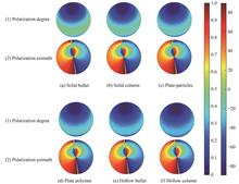
Many animals have the strange ability to sense the polarized light and navigate using the stable polarization mode in the sky, and the polarization navigation technology has been studied by mimicking the biological polarization navigation mechanism. As the information source of polarization navigation, the sky polarization mode lacks systematic research in the atmosphere of the ice cloud, which hinders the practical application of polarization navigation technology. To explore the influence of ice cloud atmospheric related parameters, such as ice crystal particle shape, effective radius, ice water content and optical thickness, on the sky polarization pattern. A vector transport model based on the Monte Carlo method, by the radiative transfer process of actual ice clouds. This paper analyzed the change law of atmospheric polarization mode of the ice cloud with different shapes with different observation height angles, the change law of atmospheric polarization of the ice cloud with different effective radii under different ice water content, the change law of atmospheric polarization of ice cloud with thickness and neutralization optical thickness under different ice water content. And through the image-type test system, the variation of sky polarization pattern with effective radius, optical thickness and ice water content in 10 sets of actual atmospheric conditions in Dalian University of Technology were tested. The results shown that the shape of ice crystal particles affects the polarization of the ice cloud and the azimuthal polarization of the ice cloud. The plate polymer particle polarization was greater than plate particles. Because the plate particles, plate polymer particles usually had larger size distribution and more complex shape, which made the light into the particle multiple scattering, reflection and refraction and larger phase difference, leading to a stronger polarization effect, and produced larger polarization. Solid column/bullet particles were larger than hollow column/bullet particles. Because the solid column/solid bullet particles inside were solid, the particle's internal medium and light contact area were larger than the hollow particles, resulting in the scattering, reflection and refraction of the phase difference. The polarization effect was relatively strong, so the polarization was larger. And the atmospheric polarization of the ice cloud increases with the effective radius. Because of the fact that when the effective radius was small. The relative size of the light in the clouds was relatively close to the particles. Scattering and refracted light had relatively weak effects on the polarization effect. While, as the effective radius increases, the surface area and size of the ice crystals were also becoming larger. The larger surface area and size of the ice crystals increase the scattering, reflection, and refraction of light inside the ice crystals. Thus leading to an increased phase difference, Producing stronger polarization effects. Therefore, the degree of polarization value will also increase. The atmospheric polarization of ice clouds decreases with increasing optical thickness and ice water content. After it gradually tended to a stable state. Because the increasing optical thickness, light rays travel through longer paths in the medium, so that the energy of the light is more evenly distributed throughout the ice cloud, when the optical thickness increases to a certain value. Light propagation path and energy distribution gradually tended to a steady state. Thus, the atmospheric polarization of the ice cloud gradually tended to a stable value. The actual tests were conducted at the same time on different dates and it found that the polarization variation law of the actual ice cloud in the Dalian University of Technology was basically consistent with the simulation, which verified the reliability of the simulation model. The study in this paper provides theoretical support for the engineering application of polarization navigation under the actual ice cloud atmospheric conditions.
Nov. 25, 2023Vol. 52 Issue 11 1101001 (2023)
Zitong LI, Jiankang ZHAO, Jingran XU, Haihui LONG, and Chuanqi LIU
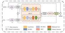
Remote sensing images are widely used in land monitoring, environmental perception, disaster prediction and urban analysis. Most commercial satellites such as WorldView-4, QuickBird and WorldView-2 are equipped with sensors that can obtain panchromatic images and multispectral images at the same time. Panchromatic images have high spatial resolution but have only one band. The spatial resolution of multispectral images is low due to the bandwidth limitation of the equipment. In order to obtain more accurate details of the measured object, panchromatic image and multispectral image can be fused to generate images with both high spatial resolution and high spectral resolution. Fusion methods of multispectral and panchromatic images can be divided into four categories: multi-resolution analysis method, component substitution method, variational optimization method and deep learning method. Compared with traditional methods, deep learning has stronger feature extraction ability, so it is widely used. Currently, transformer structure is introduced into advanced remote sensing image fusion method. Aiming at the problem that existing methods based on transformer fail to fully integrate multi-scale features of remote sensing images, this paper proposes a multispectral-panchromatic fusion network MSCANet, based on improved Swin transformer. The model extracts features of multispectral images and panchromatic images respectively by using two-flow branches. The downsampled feature images are cascaded and fed into the fusion network. In order to improve the robustness of feature extraction in various complex ground scenes, a Multiscale Swin-transformer with Channel Attention (MSCA) unit is integrated in the fusion part. The unit replaces the MLP part of Swin transformer into a cascade module of multi-scale convolution and channel attention, which can better fuse the feature information of ground objects of different sizes in remote sensing images and use the long-range dependence between regions. The fusion network focus on predicting the high-frequency details lost in multispectral images. Then high frequency details are added to the original image to restore a high resolution multispectral image. Simulation experiment and real experiment of three commercial satellites are conducted. In the experiment of simulation data, the fusion results were evaluated by calculating the difference between the reference image and the simulation dataset. Compared with other methods, MSCANet has the best performance in visual performance and quantitative metrics. Compared with the method with the second performance, the ERGAS index of MSCANet in the three datasets decreased by 11.99%, 0.4% and 3.43%, respectively. In the experiment of three real datasets, combining visual effect and quantitative metrics analysis, the result of MSCANet is the best. Ablation experiments were conducted for the three fusion strategies proposed in this paper. The experimental result shows that the injected model used in this paper outperforms the non-injected model. It also proves that the replacement of MLP module in MSCA module and the addition of attention mechanism are conducive to the improvement of fusion performance. Also, the addition of spectral loss and spatial structure loss on the basis of MAE loss is effective for the improvement of spectral fidelity and spatial resolution. In conclusion, the effectiveness of the proposed method was verified by comparison and ablation experiments. In future work, MSCANet is expected to be migrated to the fusion of multispectral image and hyperspectral image, visible image and infrared image, and other similar tasks to improve the generalization of the model proposed in this paper.
Nov. 25, 2023Vol. 52 Issue 11 1110001 (2023)
Yinzhu CHENG, Song LIU, Nan WANG, Yuetian SHI, and Geng ZHANG
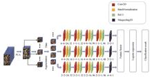
Remote sensing image classification is a key branch in remote sensing image processing, which provides an important basis for agricultural, industrial, and military applications. With the development of remote sensing satellite, spectral imaging technique has also developed from multi-spectral technology to hyperspectral technology. Rich spectral information puts forward higher requirements for remote sensing image classification. Many hyperspectral image classification algorithms based on traditional methods, such as superpixel methods, extended morphological feature methods, space-spectral joint classification algorithms based on combined kernels, and classification algorithms based on support vector machines and graph cuts, have achieved certain results. In recent years, benefiting from the improvement of hardware conditions and the update and iteration of algorithms, various deep learning methods have emerged one after another, and have been introduced into the field of hyperspectral image classification by researchers, further improving the accuracy of hyperspectral classification. Autoencoder, Convolutional Neural Network(CNN), and capsule neural network have all been experimentally verified to be effective in this field. Different from the common two-dimensional convolutional neural network, the convolution kernel of the three-dimensional convolutional neural network (3D CNN) is a cube, which can naturally integrate the features of spatial dimension and spectral dimension, and has achieved state-of-the-art performance in the field of remote sensing image classification. Conventional 3D CNN usually extracts data cube features from a single scale, which often loses certain local information; excessively increasing the depth of the model will lead to overfitting problems; limited by actual conditions, it is often difficult to obtain hyperspectral data with a large number of labels, while conventional 3D CNN does not perform well for few-sample situations (for example, the total sample size is only a few hundred). To solve these problems, a multi-branch 3D CNN is proposed in this paper, and the three branches are designed with three different 3D CNN structures. For the input hyperspectral data image set, this paper first utilizes the principal component analysis method to reduce the dimensionality of the data, and the dimensionality of the spectral dimension is selected as 40 after dimensionality reduction. The data cube is decomposed into many 19×19×40 image patches, and the label of its central pixel is used as the label of the image patch, and then the method of rotating 90 degrees, 180 degrees, and 270 degrees is introduced for data augmentation. In the feature extraction stage, a three-dimensional convolutional neural network connected in parallel with three branches is employed to extract features from three spatial scales of 2×2, 4×4, and 6×6. In the training phase, Adam optimizer is used to optimize the parameters of the three branches, respectively, and the cross-entropy loss function is adopted. In order to alleviate overfitting, the dropout unit and Batch Normalization are introduced. In the test phase, the features extracted from the three branches are combined by weighted connection, and the optimal weighting coefficient is optimized by utilizing simulated annealing algorithm. In terms of classifiers, the logistic regression classifier is adopted, which has performance not inferior to fully connected neural networks for small-sized and medium-sized data sets. In order to verify the effectiveness of the method in this paper, 10% of the labeled data were used for training on public datasets such as Indian Pines, Pavia University, and Salinas, the overall accuracy of 98.60%, 99.83%, and 99.97% were respectively obtained. Our method outperforms the comparative methods such as support vector machine, 2D CNN, and conventional 3D CNN. Moreover, the overall accuracy of the method in this paper is studied when the amount of data in the training phase gradually decreases, and compared with the single-branch 3D CNN with data augmentation, multi-branch 3D CNN without data augmentation, single-branch 3D CNN without data augmentation. The method in this paper is also compared with the DAMA and DBDA methods in the case of a few samples. Compared with the comparison method, the performance of the method in this paper still maintains a high classification accuracy when the sample size is small. In addition, a practical test was carried out using the method in this paper. A series of experimental results show that compared with various comparison methods, the method proposed in this paper has a good classification accuracy and has high application value for hyperspectral image classification problems.
Nov. 25, 2023Vol. 52 Issue 11 1110002 (2023)
Xin FENG, Jieming YANG, Hongde ZHANG, and Guohang QIU
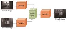
In the infrared and visible image fusion task, the visible image contains a large amount of texture and background information, while the infrared image contains obvious target information. The two complement each other and can effectively and comprehensively represent the visual information of a scene. In order to improve the problem of partial feature loss between infrared and visible fusion image and source image, and fully extract the feature information in infrared and visible image, this paper proposes an improved dual channel deep learning auto-encoder network for infrared and visible image fusion. The encoder is composed of three cascaded dual channel layers, and they are composed of the cascaded residual and dense connection modules. The source image is divided into two paths and input the residual connection network and the dense connection network at the same time. The residual connection network has a good effect in highlighting the target features. And the dense connection is good at preserving the texture details of the source image, so the encoder structure can fully extract the multi-level features of infrared and visible images. In the design of fusion layer, the spatial L1 norm and the channel attention mechanism are respectively used to fuse the cascades of residuals and dense channel features. The spatial L1 norm fusion strategy uses the L1 norm to calculate the value of activity level measurement and lays more emphasis on the fusion of spatial information. The channel attention mechanism obtains the weight graph of each channel through the global pooling operation. The information contained in each channel can be measured by weight so that the channel information can be fused effectively. Finally, the corresponding decoder is designed to reconstruct the fusion feature image, and the decoder processes the dense and residual features differently according to the characteristics of the encoder. The dense feature layers in high dimension are deeper, so more convolutional sampling layers are used to restore the features; the residual feature layers in low dimension are sharer, so the number of convolutional layers is reduced. In this way, the features of different channels and levels are combined to obtain the final fusion result. In the network training stage, the fusion layer is removed, and 5 000 images are randomly selected from the ImageNet data set as the training set for the auto-encoder network. Meanwhile, the sum of pixel loss, gradient loss and structural similarity loss is used as the loss function to guide the optimization of network parameters. In the experimental phase, the network structure and fusion strategy of the ablation experiment. In terms of network structure, the comparison with single residual or dense channel network proves that the two-channel network structure indeed improves the feature extraction ability. In terms of fusion strategy, the comparison with classical fusion strategies such as addition, mean and maximum proves that the dual path fusion strategy can give play to the advantages of the dual channel structure. It can effectively integrate the salient features and detail features of the source image. Finally, the proposed method is compared with the traditional and the latest deep learning algorithms in recent years. The results show that the proposed method can better reflect the target features and background contour information subjectively, and can maintain the information balance between infrared and visible images in most fusion scenes, so as to obtain high-quality fusion images. In the objective indicators CC, PSNR and MI is in the lead, the rest of the indicators are also in the middle level, with excellent comprehensive performance.
Nov. 25, 2023Vol. 52 Issue 11 1110003 (2023)
Xianfeng XIE, Jia QIAN, Xing LI, Shipei DANG, Chen BAI, Junwei MIN, Dan DAN, and Baoli YAO
In the research fields such as biomedicine and material science, researchers need to observe the Three-dimensional (3D) structure of samples. This promotes the development of 3D optical microscopic techniques, such as Laser Scanning Confocal Microscopy (LSCM), Light Sheet Fluorescence Microscopy (LSFM), Optical Sectioning Structured Illumination Microscopy (OS-SIM). Among them, OS-SIM has the capability of extracting the in-focus target information from the out-of-focus background of the sample to enable 3D optical imaging. The quality of the optical sectioning image is directly related to the reconstruction algorithm. Although the traditional RMS algorithm is simple, the reconstructed image is often poor when the signal-to-noise ratio and the fringe contrast of the original image are not high, and the 3D reconstructed image is not ideal. To overcome the deficiencies of the RMS algorithm, a number of methods have been proposed, such as the Fast and Adaptive Bi-Dimensional Empirical Mode Decomposition-Hilbert Spiral Transform (FABMED-HS) method, Sequence Hilbert Transform (SHT) method, Fourier-OS-SIM method. All these methods provide different ideas for realizing 3D microscopic imaging.In this paper, we propose a new method, which can obtain high fidelity optical sectioning images. This method combines background removal and deconvolution processing, and finally obtains the optical sectioning image using standard deviation operation. Compared to the traditional RMS algorithm, the proposed method can effectively reduce the residual fringes and improve the visibility of minute details. Even in the low contrast of structured illumination where the RMS algorithm works abnormally, the STD algorithm can still perform well. Because the reconstruction formula of this method is similar to the standard deviation formula, the proposed method is named“STD (Standard Deviation) algorithm”. Experimentally, a Digital Micro-mirror Device (DMD) based structured illumination microscope is built. In this microscope, a Laser Diode Illuminator (LDI) is used as light source that provides illumination of seven wavelength channels. The DMD has a resolution of 1 920×1 080 pixels, with a pixel size of 7.56 μm×7.56 μm. The SCOMS camera has a resolution of 2 048×2 048 pixels, with a pixel size of 6.5 μm×6.5 μm. Firstly, we compare the reconstructed images of STD algorithm and RMS algorithm using mouse kidney cells and Bovine Pulmonary Artery Endothelial (BPAE) cells as samples. The experimental results demonstrate that RMS algorithm has better optical sectioning capability. The STD algorithm is also applied to previously collected data with a mite as the sample. The experimental results again suggest the robustness of the STD algorithm. And then, we find that changing the illumination wavelength has little effect on the imaging position, which makes it possible to optical sectioning at multiple wavelengths. We obtain dual-wavelength fluorescence images by using 470 nm and 555 nm to excite the mouse kidney cells samples. Finally, 3D imaging experiments is performed with pollen samples. The field-of-view of the image is 163.84 μm×163.84 μm. We took 125 layers of images, each thickness is 200 nm. Using the STD algorithm, we get sharp 3D images. All the above experimental results demonstrate that the STD method can obtain better optical sectioning 3D images compared to the RMS method.
Nov. 25, 2023Vol. 52 Issue 11 1110004 (2023)
Fang LIN, Wenqing LIU, Yu WANG, Zhen CHANG, and Fuqi SI
This paper designs an automatic full-well test system based on PTC technique. This system is applied to measure the full-well and readout noise of CCD cameras to improve the development conditions for the imaging circuits design. Scientific CCDs usually have deeper full-well capacity and lower readout noise, making it suitable for measurement instruments with large dynamic range and high accuracy. The project mentioned in this paper is a satellite-born instrument measuring the components of atmosphere, which employs a spectrometer and a camera to capture the spectral image data of the atmosphere. Since the brightness of the target varies in a wide range, the measurement requires a large dynamic range of the camera. In addition, to obtain an adequate image spatial resolution when the camera is scanning along the trail of the satellite, the readout rate of the CCD is determined to be 2.5 MHz. E2V's scientific product CCD275 is selected to make the new camera. According to the datasheet of CCD275, it has a full-well capacity of over 700 ke- and a maximum readout rate of 5 MHz. However, the maximum readout speed specified in the datasheet is not the speed, at which the CCD full-well performance can be guaranteed. The CCD factories usually measure the full-well capacity at a low readout speed, and obtain the maximum readout speed under the condition that imaging function is achieved. The full-well of a CCD is determined by the storage and transferring capability of the CCD. The charge transferring capability is affected by offset voltage, driving current, and clock phases, which are the design parameters of the imaging circuit in the camera. Theoretical calculations and design references can only provide rough ranges of these circuit parameters. In a low readout speed, these parameters do not significantly affect the full-well transferring capability. However, when the readout speed is increased close to a certain speed, the effect becomes significant and these parameters need to be finely adjusted to keep the full-well performance. Over the certain speed, however the parameters are adjusted, the CCD can not output full-well. The required speed of 2.5 MHz is the speed, at which the design parameters are needed to be finely adjusted for the best performant. When a parameter is changed, the full-well measurement on the camera is required to provide feedback. Due to the numbers of parameters and their complex relationship, during the development of the new camera, such adjustments and measurements are required in a large number of times. The process of full-well test with PTC method is quite complicated and each test also takes a lot of time. To improve the development condition, this paper investigates PTC technique and designs an automatic CCD full-well test system. The system includes a test bench and a software. The test bench is comprised of an integrating sphere, a dark box, the camera to be tested, the stands supporting all the devices, and a computer. The software implements the data acquisition and data processing. By adjusting a remote controlled current source, which drives halogen lamps in an integrating sphere, the software sets up flat-field light at different illumination levels. In each illuminance, the software acquires an image data from the camera. Each image contributes a point to the PTC, the horizontal ordinate is the average value of the image and the vertical ordinate is the variance. Densely acquiring the points of PTC will slow down the test, as every time of adjusting the light source takes a time to stay stable. On the other side, less points of the PTC will reduce the precision of the measurement, as break point of the curve, which is the full-well point, will be difficult to be located. This paper creates a novel PTC plot method called“quick-PTC-plotting”, to shorten the acquisition time without any decline of the precision. It firstly adjusts the light source with a large step and acquires corresponding images, roughly plotting a PTC with few points. Then it determines a narrow range, where the break point of PTC most likely exists, obtains images with a small step in the narrow range, and re-plots the PTC. The software implements the“Quick-PTC-plotting”and reduces the times of light adjusting. The software also acquires dark images and background images, which are used for the calculations of the PTC. The automatic CCD full-well test system has been applied in the real engineering. The methods and implementations have been verified. Statistic result shows the random error of the system is ±0.6%. Four space-grade CCDs, of which the full-well capacities have been tested by the factory with lower speed, are also tested in the system. The deviation of the tests in factory and the automatic system is less than 1%. The accuracy of the test system is adequate for the application of camera development. The automatic system shortens the full-well test time to 20 min, while manual operation takes 2 h. It also brings a benefit of unattended operation.
Nov. 25, 2023Vol. 52 Issue 11 1111001 (2023)

Long GAO, Xianjie LI, Chao AN, Zongyao OU, Peisi WANG, Ziqi SONG, Yuliang TAO, and Jin WU
Synthetic Aperture Imaging Lidar (SAIL) is limited by the optical heterodyne detection antenna theorem, the SAIL technology with the single detector is essentially a small field of view imaging. Breaking the limitations of the optical antenna theorem for wide field of view mapped band imaging is a bottleneck problem. In traditional methods, linear array detectors are generally used for wide-field imaging, but this method has imaging pixel spacing and cannot achieve 100% duty ratio imaging. For the application of small target imaging, the gap between pixels can cause serious loss of SAIL image information. Aiming at the above problems, this paper proposes the novel optical system of field division coherent receiving and transmitting lidar received by a 4×4 pigtail microlens array, which can realize the optical imaging technology of long distance and large field division lidar, improves the imaging efficiency of the system, and realizes seamless coverage imaging. The coherent receiving and transmitting lidar is a bistatic system with the wavelength of 1 550 nm with the advantage of eye-safety. The transmitter system is composed of beam splitter, half-wave plate, expand telescope, and the divergence angle of the laser beam equal to 105 μrad, and the output laser beam is a circular polarization state. Meanwhile, there is a local laser beam act as the monitor system. The receiver system is composed of receiver telescope, quarter wave plate, 4×4 microlens array, and the field of view of the receiver system equal to 175 μrad. Furthermore, there are the optical axis monitor module, which is composed of two cameras with a smaller field of view and a bigger field of view. It is verified by experiment that the light spot mode, array number and system microlens surface parameters of the pigtail microlens array also meet the index requirements. At the same time, the theoretical calculation model of the optical efficiency of the full field of view with 175 μrad is carried out. The simulation results show that the optical efficiency of the full field of view system can reach 65.5%, which meets the requirements of the system index. Meanwhile, the coupling efficiency of the 16-channel central field of view of the 4×4 microlens array with the single mode fiber has also been tested. The test results show that the average optical coupling efficiency is 73.1%, the maximum value and the minimum value of the coupling efficiency are 75% and 72%, respectively. In addition, aiming at the requirements of the optical axis deviation of SAIL transceiver optical system, a 16-channel transceiver optical axis test system was built by using 12 m collimator, 1 550 nm beam quality analyzer and other equipments, such as, the cube mirror, 1 550 nm beam splitters. And the optical alignment test of the light-receiving axis deviation was completed. The light-receiving axis deviation is less than 4″, and the maximum value and the minimum value of the axis deviation are 1.1″and 7.2″, respectively. which can meet the requirements of lidar imaging experiment.
Nov. 25, 2023Vol. 52 Issue 11 1111002 (2023)
Haolong LUO, Jiansheng LI, Danping ZOU, Zidi YANG, and Guangyun LI
Optical motion capture systems are devices used to track and capture target movements and obtain the position and attitude of the target in real time. In practical tasks such as UAV obstacle avoidance, vehicle-machine co-positioning and multi-machine co-operation, optical motion capture systems are required to provide reliable and high-precision positioning coordinates for targets. On the one hand, the optical motion capture system provides high-precision positioning coordinates for the target to assist in tasks such as navigation and obstacle avoidance; on the other hand, the optical motion capture system provides high-precision positioning true values for the target to verify the accuracy of the positioning and navigation algorithms. However, the actual positioning accuracy of the optical motion capture system is often much lower than the manufacturer's nominal accuracy due to factors such as the camera distribution, number of cameras in the optical motion capture system and vibrations in the field. Therefore, it is urgent and necessary to verify the actual positioning accuracy of optical motion capture systems in large scenes. Especially in large scenes, optical motion capture systems suffer from scattered camera distribution, a small number of cameras in the common viewing area, and long camera-target distances, resulting in inaccurate positioning. If the actual positioning accuracy of the optical motion capture system is significantly different from the nominal accuracy, the performance of the motion capture system will be greatly reduced and it will be difficult for the motion capture system to perform its actual function. In general, the positioning accuracy of the optical motion capture system is mainly tested in small spaces, and the positioning accuracy of the system is often assessed in terms of repeated trajectory accuracy, resulting in the actual positioning accuracy of optical motion capture systems in real scenes, especially in large scenes, being unknown or inaccurate. To solve the problem of precision detection of the optical motion capture system in large scenes, a method of calibrating the positioning accuracy of the optical motion capture system in large scenes using total station is proposed. First, select several common points evenly in the four sub-regions where the optical motion capture system is located. Second, the concentric target ball workpiece of the same size is used to solve the problem that the measuring points of the total station and the optical motion capture system are inconsistent. Third, the real value and measured value of the common point are obtained through the measurement of the total station and optical motion capture system and the position and posture transformation matrix between the total station coordinate system and the optical motion capture system coordinate system is calculated based on robust least squares iterative algorithm for Rodrigues matrix. Finally, the positioning accuracy of the optical motion capture system in the sub-region and the whole region is calculated under the unified coordinate system. Meanwhile, the external parameter calibration of the measurement system and the Vicon system is realized based on the above method. The experimental results show that the positioning accuracy of the four sub-region optical motion capture systems is 2.385 mm, 0.877 mm, 1.787 mm, 2.890 mm respectively, and the positioning accuracy of the optical motion capture system in the whole region is 8.126 mm. It shows that the positioning accuracy of the optical motion capture system is significantly reduced in large scenes, and the feasibility and effectiveness of using the total station to calibrate the optical motion capture system and external parameters of the motion capture system are verified. With the increasing application demand and positioning accuracy requirements for optical motion capture systems, the proposed method is an inspiration and reference for future calibration of optical motion capture systems in large and complex scenes.
Nov. 25, 2023Vol. 52 Issue 11 1111003 (2023)
Huizhen YANG, Xiangdong ZANG, Zhiguang ZHANG, and Jinlong LIU
The Wavefront Sensorless (WFSless) Adaptive Optics (AO) system is simple and easy to implement because it does not require a wavefront sensor and can be applied to some environments where conventional adaptive optics systems cannot work, such as multiphoton microscopy for biological imaging. The WFSless AO technology has not been adopted pervasively in the early days due to the lack of suitable control algorithms. With the emergence of new optimization algorithms recently, it has been widely studied and applied in related fields. Metaheuristic algorithms, e.g., Genetic Algorithm (GA), Particle Swarm Optimization (PSO), and Differential Evolution Algorithm (DEA) are commonly used as the control algorithms of WFSless AO systems. However, these algorithms have some problems, i.e., slow convergence speed, insufficient global search efficiency, and poor adaptability to different wavefront aberrations, which make them insufficient to be applied in practice.We propose to adapt the RUNge Kutta optimizer (RUN) to the system control algorithm in this paper. An adaptive optics system model based on the RUN optimization algorithm is established with a 61-element deformable mirror as a wavefront correction device. Wavefront aberrations with different turbulence levels are used as correction objects. The performance, speed, and local extreme values of the optical systems based on RUN, PSO, DEA, and GA algorithms are compared and analyzed.Results show that all four algorithms can obtain good convergence, and performance metrics of the RUN algorithm and GA are similar and obviously better than those of PSO and DEA after convergence is achieved. The Analysis of convergence speed shows that the speed decreases with the increase of turbulence level, but the RUN algorithm is significantly faster than other three algorithms. Compared with PSO, DEA, and GA, the convergence speed of the RUN algorithm is about 4.5, 3.3, and 3.5 times faster under D/r0=5, about 3.9, 3.8, and 4.1 times faster under D/r0=10; and about 3.8, 3.4, and 5.3 times faster under D/r0=15, respectively. Additionally, compared with other algorithms, RUN has a lower probability of falling into local extrema which shows the RUN has better convergence stability and better robustness. Additionally, we also find that the control algorithm is insensitive to parameters and easier to implement.The RUN optimization algorithm has strong adaptability and fast convergence for aberrated wavefronts correction under different turbulence levels when it is used as a control algorithm of WFSless AO systems. The proposed control method outperforms other classical metaheuristic algorithms and has great application potential in microscopic imaging, spot shaping and other fields. Above research results can provide a theoretical basis for the practical application of wavefront correction systems based on the RUN optimization algorithm.
Nov. 25, 2023Vol. 52 Issue 11 1111004 (2023)
Jun XIE, Heng LI, Yanli BAI, and Fengxiang Cui
The picoseconds framing camera is an ultrafast diagnostic device, which effectively measure the spatio-temporal evolution of plasmas at the implosion stage of fusion in the inertial confinement fusion experiments. The temporal resolution of the Microchannel Plate (MCP) framing camera is 60~100 ps, that closely related to the thickness of the MCP and the parameters of picoseconds gating pulse. Although the temporal resolution is improved using the 0.2 mm MCP, the thin MCP is difficult to widely apply due to the poor signal-to-noise ratio and high fabrication requirements. Therefore, for the MCP farming camera, the higher performance of the picoseconds gating pulse is gradually became an important research work. Currently, the picoseconds gating pulse is generated by the Marx generator and the pulse shaping circuit, however, due to the complex multistage structure and the higher voltage discharge ignition, the maintenance work is tedious, therefore, it is necessary to design picoseconds gating pulse using the a method of the simple topological circuits and the high voltage device.In order to explore the new technology and expand the development of high-power pulse technology of the ultrafast diagnostics, in the course of studies of the gating pulse of the MCP framing camera, firstly, the basic characteristics of the magnetic switches and transformers are introduced, the working principle and topology structure of the circuit of magnetic element are sketched, the influence of circuit parameters on output performance is analyzed; Secondly, the multilevel magnetic pulse compression circuit is designed based on the excellent switching performance of the magnetic components and the principle of the pulse compression, which included foundation, first and second level. The influence of circuit parameters on the amplitude and the Full Width at Half Maximum (FWHM) of the gating pulse are analyzed, that included the DC power supply, the reset current, the charging capacitor and the turns ratio of magnetic switch. The optimal output of the gating pulse is discussed; Lastly, according to structure of the MCP, the dynamic multiplication model of photoelectron in the MCP channel is built using the Monte Carlo method, and the optimal output of the gating pulse is loaded on the model, the number of secondary electrons, the axial displacement and the transport time are analyzed, the corresponding gain of the photoelectron through the MCP channel is calculated, and the temporal resolution of the MCP framing camera is achieved by the curve of the time and gain on the MCP.The picoseconds gating pulse is realized by the multilevel magnetic pulse compression circuit. With increasing the DC power supply and reset current, and decreasing the charging capacitor and the turns ratio of magnetic switch, the amplitude of the gating pulse is gradually improved. With decreasing the DC power supply, reset current, the charging capacitor and the turns ratio of magnetic switch, the FWHM of gating pulse is gradually narrowed. When the DC power supply is 500 V, the reset current is 1 A, the inductance of the magnetic switch is 1 μH, the charging capacitance of the primary coil circuit is 4 μF, the turns ratio of the transformer is 10∶1, the turns ratio of the magnetic switch coil is 1∶2, and, the charging capacitance of the secondary coil circuit and the two-stage magnetic switch circuit is 1 pF, the amplitude and the FWHM of the gating pulse are -3.2 kV and 149 ps, respectively. As the gating pulse is loaded on the dynamic multiplication model of photoelectron, the temporal resolution is achieved to about 89 ps by calculating the corresponding gain of the photoelectron through the MCP channel and constructing the curve of the time and gain on the MCP.Based on the excellent switching performance of the magnetic components and the principle of the pulse compression, the multilevel magnetic pulse compression circuit is designed using the magnetic switches and transformers, the gating pulse with the high amplitude and the narrow FWHM is realized by optimizing and matching the circuit parameters. While the gating pulse is loaded on the dynamic multiplication model of photoelectron, the curve of the time and gain on the MCP is constructed and the temporal resolution of the MCP farming camera is calculated. The research results show that, it is feasible to utilize the magnetic pulse compression circuit generated the gating pulse, which is appropriate for the MCP framing camera. And the higher performance is realized by adjusting the direct current power supply, the reset current, the charging capacitor and the turns ratio of magnetic switch. In conclusion, this research can provide a new idea for the picoseconds gating pulse of the MCP framing camera.
Nov. 25, 2023Vol. 52 Issue 11 1111005 (2023)
Ruiliang ZHANG, Suheng PENG, Bingwen WANG, Lijie GENG, Yusheng ZHAI, Zhifeng ZHANG, Fengxiao ZHAI, and Kun YANG
Nonlinear optical parametric conversion process based on Stimulated Polariton Scattering (SPS) is an effective way to generate tunable terahertz waves and near-infrared Stokes light with high efficiency. In order to make the SPS process effective, non-collinear phase matching is used to keep the three waves in the crystal at the same phase velocity. Non-collinear phase-matched terahertz wave parametric sources mainly use parametric oscillators and seed-injected parametric generators to achieve frequency limitation and tuning. This paper proposes a new method to achieve non-collinear phase matching of SPS by using two intersecting pump beams to simultaneously excite SPS. The SPS along the transmission direction of the center of the intersection of the pump beams has the same phase matching relationship, and Stokes can obtain the maximum parametric gain and continuous amplification. The SPS in other directions is suppressed by the combined action of a pump beam that satisfies phase matching and a pump beam that does not satisfy phase matching. This method can achieve non-collinear phase matching without relying on a resonant cavity and can be used for short-pulse laser pumping. The basic principle of parametric amplification is studied theoretically, and the gain formula of parametric amplification is derived. Taking cross-pumping based on total reflection of pump light on the side of the crystal as an example, the phase matching relationship of cross-pumping SPS is analyzed, and the phase mismatch of SPS in different transmission directions and the single-pass parametric gain expression of Stokes light are obtained. The gain efficiency curve is obtained through numerical calculation, revealing the physical mechanism of cross-pumping to achieve non-collinear phase matching of SPS. In the experiment, cross-pumping was achieved by grazing incidence of pump light on the side of the crystal at a certain angle to achieve total reflection. By rotating the angle of the crystal, the intersection angle of pump light and phase matching conditions are changed, thereby achieving frequency tuning of Stokes light and obtaining tunable narrow-band Stokes light output. The wavelength tuning range of Stokes light is 1 068~1 076 nm, and the highest output is obtained near 1 071 nm. The measured angle tuning characteristics are consistent with theoretical values, indicating that cross-pumping to achieve SPS phase matching follows the basic principles of nonlinear optical phase matching. The measured line width of Stokes light is 0.17 nm, the lateral divergence angle is 0.053°, and the longitudinal divergence angle is 0.66°. In the experiment, a cascading phenomenon similar to that in a cross-pumped terahertz parametric oscillator was found. The pulse width of Stokes light is related to the energy of the pump light. Within a certain range, the larger the incident pump light energy, the wider the pulse width of Stokes light and the shorter the establishment time. When the pump light energy increases from 8 mJ to 14 mJ, the pulse width of Stokes light increases from 2 ns to 4 ns. The relationship between the output energy of Stokes light and the incident pump light energy was measured. The threshold pump energy for producing Stokes light is about 7 mJ, corresponding to a pump intensity of 120 MW/cm-1. The highest Stokes light output energy is 1.07 mJ at a pump energy of 15 mJ, corresponding to an energy conversion efficiency of 6.8%, and there is no energy saturation phenomenon as the pump energy increases. Using a silicon prism array to couple out terahertz waves, the relationship between the output energy of THz waves and the pump light energy was measured and compared with the output THz wave energy of a shallow surface cross-pumped terahertz wave parametric oscillator with an external resonant cavity. It is found that the efficiency of cross-pumping SPS increases with increasing pump intensity. It can be expected that under sub-ns short-pulse pumping, due to the crystal's ability to withstand a pump intensity of 2 GW/cm-1, the gain coefficient can be increased several times, and the efficiency of cross-pumping SPS can be further greatly improved. This research provides a reference for phase matching methods in nonlinear optical processes, especially suitable for short-pulse situations where the pump light pulse width is less than sub-ns.
Nov. 25, 2023Vol. 52 Issue 11 1114001 (2023)
Kun HE, Xiaoliang ZHAO, Jun WANG, Bixin LI, Bin DU, and Yanlong WANG
In recent years, as population growth and industrial development have led to rapid growth in global energy demand, the dwindling traditional fossil fuel resources and the increasing difficulty of extraction may not be able to meet the energy consumption of the future world. Therefore, researchers are committed to finding clean renewable energy sources as alternatives to traditional fossil fuels. As one of the most abundant renewable energy sources on earth, photovoltaic technology, which converts solar energy (light energy) into electrical energy, is receiving more and more attention due to its advantages such as cleanliness and feasibility. Since its birth in 1954 at Bell Laboratories in the United States, solar cells have developed through three generations over the past 70 years. Silicon-based solar cells produced on silicon wafers are the first generation of solar cells and still dominate the global solar cell market with high Power Conversion Efficiency (PCE) and high stability. However, high raw material costs and cumbersome high-temperature processing manufacturing processes restrict its further development. Thin-film solar cells based on inorganic semiconductor films such as amorphous silicon, copper indium gallium selenide, and cadmium telluride are called second-generation solar cells. Compared with silicon-based solar cells, the cost of raw materials for thin-film solar cells is reduced, but in order to obtain optimal performance, high-vacuum film deposition and high-temperature annealing are still required, which further increases processing costs. At the same time, the raw materials are toxic and are not conducive to large-scale mass production. Therefore, although both the first-generation and the second-generation photovoltaic cells can achieve PCE of more than 20%, complex processing techniques and high costs limit their future development. These problems force scientists to focus on Moving to third-generation solar cells manufactured using low-cost technologies. The third generation of solar cells are collectively called new solar cells, including dye sensitized solar cells (DSSCs), quantum dot solar cells (QDSCs) and perovskite solar cells (PSCs). Organic-inorganic halide PSCs have attracted much attention due to their simple fabrication process, low cost, and high efficiency. Over the past ten years, due to huge research efforts in composition, process and defect passivation, the PCE record of PSCs devices has soared to 26% in just over ten years since their introduction in 2009, which is close to that of silicon-based devices solar cell efficiency record. At present, it ranks third in single-junction photovoltaic cells and still has great development potential in the future. From this perspective, we briefly review the development of PSCs from discovery to laboratory research to commercialization progress. In this paper, the structure and properties of hybrid perovskite materials are introduced. Following that, the evolution of key components and device structures of perovskite solar cells since their inception are reviewed. At the same time, we are aware of the importance of the improvement of power conversion efficiency for the future development of perovskite solar cells. Therefore, the latest research results in the use of defect passivation strategies to improve power conversion efficiency in the past three years are summarized. Finally, the challenges faced by perovskite solar cells are described and future commercial prospects are prospected.
Nov. 25, 2023Vol. 52 Issue 11 1116001 (2023)
Yalong SHEN, Peng CHEN, Yinqian HU, Lei CUI, and Yue WANG
Over the past decades, big successful developments have been achieved in Quantum Dots (QDs) materials with unique photonic and electronic properties. In the QDs family, lead Halide Perovskites (HPs) QDs are especially recognized for excellent Photoluminescence Quantum Yield (PLQY, 70%~100%), ambipolar carrier transport, wide color gamut (150% NTSC) and low-cost solution synthesis process, making them as promising materials for Light-Emitting Diodes (LEDs) toward high-performance lighting and displays. Compared to the organic-inorganic lead HPs (MAPbX3 and FAPbX3, X=Cl, Br and I), all-inorganic cesium-lead HPs (CsPbX3) possess relatively higher stability and comparable optical properties, are more promising to fabricate devices for practical application. Since the first LEDs using CsPbBr3 Quantum Dots (QDs) emitters, the PLQY and stability of QDs have been continually increasing. Despite the rapid improvement in terms of PLQY and stability, the mass synthesis of perovskites QDs has been seldom studied but very crucial for applications. In order to overcome the performance degradation of inorganic perovskite (CsPbBr3) QDs during materials preparation with large quantities, a modified supersaturated recrystallization solution-process was proposed to prepare high-quality CsPbBr3 QDs at room temperature. By adding hydrobromic acid (HBr) to accelerate the dissolution of the perovskite precursor, and introducing Lewis acid ligand to partially replace oleylamine (OAm), to realize the effective passivation of surface defect of CsPbBr3 QDs. This method enables the synthesis of highly efficient luminescent CsPbBr3 QDs with low cost and mass production. The experiment results show that the CsPbBr3 QDs exhibit an emission peak at 517 nm with a narrow Full Width at Half Maximum (FWHM) of 17 nm. Meanwhile, the PLQY of the CsPbBr3 QDs is measured to be as high as 95%. The X-Ray Diffraction (XRD) patterns of the CsPbBr3 QDs show that its characteristic peaks located at 15.49°(100),21.85°(110),30.98°(200),38.17°(211),44.15°(220), which indicated the typical monoclinic structure of the CsPbBr3 QDs (JCPDS No. 18-0364). The X-ray Photoelectron Spectroscopy (XPS) implied the CsPbBr3QDs showed Br-rich composition, which the rich Br in CsPbBr3QDs probably contributes to the excellent optical properties and good air-stability properties in the ambient environment. As a proof-of-concept device, a backlit White Light Emitting-Diode (WLED) was fabricated based on the CsPbBr3 QDs. A mixture of the green CsPbBr3 QDs and commercially available red phosphor functioned as the downconverters, and separated high-energy GaN blue light sources for photoexcitation, applied to emit white light. Consequently, the WLED device shows a luminous efficacy of 48.35 lm/W under an operating current of 20 mA. Meanwhile, the WLED exhibited a typical Electroluminescence (EL) spectra which contain three emission peaks, 454 nm peak of blue chip, 517 nm peak of green CsPbBr3, and 620 nm peak of red phosphor, resperctively. Furthermore, we obtained the device with a CIE coordinate value of (0.30, 0.31) in CIE 1931 color space, which is quite close to the standard white color (0.33, 0.33). The WLED with high efficiency demonstrated the promising potential of CsPbBr3QDs for domestic lighting, backlit display, and optical communication applications.
Nov. 25, 2023Vol. 52 Issue 11 1116002 (2023)
Yanan CAI, Shaohui YAN, Yanan ZHANG, Mulong LIU, Rui ZHANG, Wenyi REN, and Baoli YAO
Optical angular momentum, which can realize the non-destructive and non-contact rotation control of micro-particle is of great significance to study the rotational mechanical properties of biological macromolecules, to understand the biocatalysis effect, and to reveal the mechanism of biological energy conversion. The angular momentum is comprised of spin angular momentum and orbital angular momentum. Spin angular momentum is associated with the polarization of the optical field and can cause particles to spin. Orbital angular momentum comes from the helical wave-front structure associated with the central phase singularity of the optical field and can cause particles to make circular trajectories. Normally, the orientation of the angular momentum is parallel to the optical axis (the direction in which the beam propagates), which is called the axial angular momentum. Such optical fields can induce particles to rotate around the optical axis when interacting with particles. In recent years, transverse spin angular momentum has been found in structured light fields such as evanescent, interference, and focusing field. Different from the traditional axial angular momentum, transverse spin angular momentum can drive the particle to rotate in the direction perpendicular to the optical axis, introducing a new degree of freedom for optically induced rotation technology, which is therefore expected to improve the flexibility of optically induced rotation. At present, non-axial rotation control of particles in the evanescent and interference fields have been implemented. However, the effect of transverse spin angular momentum in focusing fields still needs more attention and much deeper investigation. This paper will show some theoretical and experimental results on such an effect. A circularly polarized beam is believed to carry axial spin angular momentum. As a result, it is hard to realize transverse spinning of particles in such a beam. Nevertheless, under tight focusing, the focusing fields of such beam may carry transverse spin angular momentum. Optical vortex beams carry orbital angular momentum, and can induce orbital rotation of particles. In tightly focused vortex beams, there also exists induced spinning motion of some particles. Optical vortex beams with circular polarization carry both spin angular momentum and orbital angular momentum, and can realize non-axial spinning and orbiting motion of particles. Here, the dynamics of optically induced motion of circularly polarized vortex beams are studied. By use of T-matrix method, the optical forces and torques exerted on a particle are evaluated, and the influence of the orientation of spin angular momentum and orbital angular momentum on the non-axial spinning motion of particle is analyzed. The numerical results show that in the tightly focusing fields of circularly polarized vortex beams, the particle is trapped near the intensity maxima for orbital motion. When the direction of orbital angular momentum is the same as that of spin angular momentum, the trapped particle will experience a considerable transverse spin torque in addition to the longitudinal spin torque and the orbital torque, thus will induce a non-axial spinning of particle. When the direction of orbital angular momentum is opposite to that of spin angular momentum, the transverse spin torque will be too small to drive the non-axial spinning of particle. Finally, the holographic optical tweezers system has been applied to experimentally investigate the complex motion forms of the light-induced rotation in the focusing fields of circularly polarized vortex beams. The experimental results show that the direction of orbiting motion of trapped microparticle is determined by the sign of the topological charge of the vortex beam. And when the orbital angular momentum and the spin angular momentum in the circularly polarized beams have the same direction, the trapped microparticle orbits around the optical axis while, but also experiences a non-axial spinning motion. The experimental results agreed well with the theoretical results.
Nov. 25, 2023Vol. 52 Issue 11 1126001 (2023)
Xueying WANG, and Boqin MA
Nonlinear frequency conversion is one of the key research contents in nonlinear optics. Using the external high voltage electric field poling technology to modulate the second-order nonlinear coefficient of nonlinear photonic crystals, quasi-phase-matching technology is commonly used to obtain efficient nonlinear frequency conversion. As the carrier of second-order nonlinear optical effects, optical superlattice is one of the important research topics in the field of nonlinear optics. In order to explore the advantages of different superlattice structures, more and more superlattice structures are applied to optical materials to generate harmonics of different wavelengths. Designing excellent optical superlattice structures to perform nonlinear frequency conversion has become the best solution to meet the needs of scientific research.Fractal superlattice structure has the advantage of relatively sparse arrangement in the real space and dense distribution in the reciprocal space. Therefore, fractal superlattice structure can provide highly efficient nonlinear interactions, and its advantage is more reflected in the higher-order frequency conversion. In this paper, Gosper fractal and Z fractal superlattice structures are introduced into nonlinear photonic crystals. In real space, Gosper fractal or Z fractal superlattice structure is composed of one continuous line. These two fractal superlattices can provide the complex spatial structure and rich reciprocal vectors. For Gosper fractal, it has six-fold rotational symmetry in the reciprocal space. It not only has the overall fractal dimension, but also has the boundary fractal dimension. For Z fractal, it has the periodic, quasi-periodic and fractal characteristics. The overall pattern gives the translational symmetry.The distributions of their reciprocal vectors are simulated by two-dimensional Fourier transform. The quasi-phase-matching harmonis in LiNbO3 nonlinear photonic crystals with these two superlattices are theoretically analyzed. Moreover, their diffraction experiments were carried out. The reciprocal space of the Gosper fractal superlattice can still coincide with the original pattern after the overall rotation of 60°. It means that the same harmonics can be achieved along six different directions. In the cascaded third harmonic generation, the outputs of 711.3 nm, 554.7 nm and 491 nm are obtained at different fundamental wavelengths, and their deviation angles are calculated theoretically. In the reciprocal space of Z fractal superlattice, we can make full use of the high-order transverse reciprocal lattice vectors. Second harmonics of the incident wavelength range of 1.402~1.430 μm are realized, with a minimum wavelength spacing of only 1 nm.In conclusion, the advantage of the Gosper fractal superlattice structure is the same diffraction points along six different directions. Combining the advantages of the traditional hexagon and hexagonal lattice periodic structures, it not only has high conversion efficiency, but also can realize the same multiple harmonics along six different directions. These are of great significance to the research and development of multi-channel optoelectronic integrated devices. For Z fractal superlattice structure, the reciprocal vectors are densely distributed, by which it is helpful to realize the harmonics outputs of quasi continuous wavelengths and improve the practicability of quasi-phase-matching technology. Finally, 3D Z fractal is introduced into nonlinear photonic crystal, which provides data support for femtosecond laser preparation of 3D Z fractal superlattice structure crystal. Compared with 2D crystal, the quasi-phase-matched second harmonics in 3D Z fractal crystal may be significantly improved.
Nov. 25, 2023Vol. 52 Issue 11 1126002 (2023)
Cheng HUANG, Jie SU, Jianying LIAO, Zichao LIU, Tongtong HE, and Yingbin LI
Nonsequential Double Ionization (NSDI) is a basic physical process of the interactions of strong laser fields with matter. The two electrons involved in NSDI are highly correlated, which provides a simple and effective method for understanding the electron correlation. In the past three decades, the ionization mechanism of NSDI has been studied extensively. Based on the two-hump structure of ion momentum distributions and the disappearance of the“knee”structure in the circularly polarized laser fields, the recollision model has become a very suitable ionization mechanism. The mechanism is divided into three steps. Step 1: An electron in the atom or molecule is ionized in the laser field; step 2: The ionized electron is accelerated in the laser field. When the direction of the laser field changes, the ionized electron may be pulled back and recollide with the parent ion; step 3: After recollision, the returning electron can transfer a part of the energy to the bound electron, and finally, both electrons ionize immediately or with a time delay. In linearly polarized pulses, electrons are driven by electric field force only in one direction. The returning probability is relatively high and thus results in a high double ionization yield. Therefore, early studies mainly focus on linear polarization. In this case, the control of electron dynamics is confined to one dimension. To manipulate electrons in two-dimensional space, recently, much attention has been focused on the combined electric field composed of two pulses, such as the Counter-rotating Two-color Circularly Polarized (CTCP) laser fields. By changing laser parameters, the CTCP fields can control double ionization yield, electron returning direction and returning energy. However, the waveform of the combined electric field formed by the two-colour circularly polarized pulses has multiple-fold symmetry, and the ionized electrons can return from multiple directions. If two elliptically polarized pulses are used to form a combined electric field, the multiple-fold symmetry of the electric field waveform can be broken. Thus the final emission direction of electrons and returning direction will be asymmetrical in Counter-rotating Two-color Elliptically Polarized (CTEP) fields. The ultrafast dynamics in NSDI by CTEP fields is more rich and more interesting. This paper, systematically studies the ellipticity dependence of Nonsequential Double Ionization (NSDI) of Ar atoms in CTEP fields using a three-dimensional classical ensemble model. Numerical results show that NSDI probability increases with the ellipticity of an 800-nm pulse and decreases with the ellipticity of a 1 600 nm pulse. It is because when the ellipticity of the 1 600 nm pulse is fixed, the electron returning probability and recollision energy increase with the increase of the ellipticity of the 800 nm pulse. When the ellipticity of the 800 nm pulse is fixed, the electron returning probability and recollision energy decrease with the increase of the ellipticity of the 1 600 nm pulse. Moreover, when the ellipticity of the 1 600 nm pulse is 0.3, with the ellipticity of the 1 600 nm pulse increasing the ion momentum distribution moves from the left to the right. As the ellipticities of 1 600 nm and 800 nm pulses increase, the ion momentum distribution gradually expands in the y direction and finally forms a two-layer structure distributed on both sides of the x axis.
Nov. 25, 2023Vol. 52 Issue 11 1126003 (2023)
Jiaxing WANG, Peng ZHANG, Ya ZHAO, Chuan LIU, Runpeng LIU, Yangfan DU, and Shoufeng TONG
The advancement in marine resource utilization by humans has spurred the need for performance metrics for underwater communication technology. Traditional underwater acoustic communication has reached its limitations due to its slow speed and significant delay, while submarine optical cables also present challenges in deployment and maintenance. Thus, underwater wireless optical communication technology, notable for its speed, high capacity, energy efficiency, and minimal delay, has emerged as an efficient solution to the problems of underwater high-speed wireless communication. However, the presence of underwater turbulence or aquatic organisms may lead to uncertainty in the direction of the communication emission light sources, hindering optical path alignment in the communication system and compounding the challenges of underwater wireless optical communication chain development. To address this, some strategies for underwater wireless optical communication employ mechanical fixation or manual adjustments for optical path alignment, which unfortunately limit the flexibility of the system. In light of these challenges, this paper presents the design of an underwater wireless optical communication system with optical alignment capability, providing a theoretical and practical groundwork for future underwater wireless optical communication networking.The paper proposes an underwater wireless optical dynamic communication system based on a servo system, and uses a two-dimensional waterproof photoelectric turntable as the loading platform. The platform integrates various components such as a CMOS camera, a Fresnel optical antenna, an APD detector module, and employs an external STM32F407 master controller to capture and align the signal spot at the transmission end of the system. The initial experiment tested the spot alignment accuracy of the servo system and analyzed communication rate, bit error rate, and detector sensitivity upon completing the communication optical path alignment.Following system power-up, light spots are simulated at different underwater positions by adjusting the azimuth and pitch of transmitting end turntable A. At this stage, a capture alignment command is issued to receiving turntable B, controlling it to align with the light spot. With an optical power of 30 mw at the transmitting end, the spot alignment takes 8.2 seconds when the azimuth miss distance is 815 and elevation miss distance is 697, with an azimuth alignment error of 0.17 mrad and an elevation alignment error of 0.42 mrad. After the system's optical alignment is completed, the communication performance is tested. With an error rate maintained at 10-6, the minimum signal amplitude output at communication rates of 10 Mbps, 20 Mbps, 30 Mbps, 40 Mbps, and 50 Mbps is measured. The detector sensitivity at these communication rates are -31.87 dBm, -29.03 dBm, -28.56 dBm, -27.49 dBm, and -26.74 d Bm, respectively, enabling the detection of weak light signals. The system can capture the emission spot at different positions within its field of view and sustain a stable communication link to perform communication functions.By integrating a servo system with the underwater wireless optical communication system, an underwater wireless optical dynamic communication system is designed capable of high precision optical path alignment. The system benefits from a broad field of view capture, simple structure, and high communication rate. Compared to traditional ATP laser communication systems using coarse and fine tracking modes, this system simplifies its structure based on communication distance and the underwater environment, and uses a large aperture Fresnel optical antenna to optocouple the signal into the APD detector, thereby reducing optical power attenuation. Experimental tests show that the servo system and the communication system work as expected, achieving spot capture, optical path alignment, and data communication. The results validate that the servo system can address the complex alignment of communication optical paths in underwater environments. In future work, the aim is to enhance the servo system's performance and develop its capability to track mobile communication transmitters. In addition, the communication performance of the system is optimized, fully utilizing the three optical windows of the platform to achieve duplex communication in underwater environments.
Nov. 25, 2023Vol. 52 Issue 11 1106001 (2023)
Dongya XIAO, Yuexi ZHONG, and Zhe AN
The Intensity Modulation/Direct Detection (IM/DD) system is simple and easy to implement, which is most widely used in Free Space Optical (FSO) communication. Its typical modulation schemes include On-off Keying (OOK), L-level Pulse Position Modulation (LPPM), Differential Pulse Position Modulation (DPPM) and Multiple Pulse Position Modulation (MPPM), Digital Pulse Interval Modulation (DPIM), etc. OOK is the simplest modulation scheme to implement, but the power utilization is too low and the anti-interference ability is poor. LPPM has superior power utilization at the expense of a large amount of bandwidth. Also the transmission capacity is difficult to meet the requirements of FSO communication, and strict symbol synchronization is required during demodulation, which increases the complexity of the system. DPPM improves the bandwidth utilization relatively and does not require symbol synchronization. But redundant“0”time slots are still generated in the coding process, which makes this modulation scheme not high enough in transmission capacity and bandwidth utilization. MPPM further improves the bandwidth utilization, nevertheless the error performance is poor. And strict symbol synchronization is required which increases the complexity of the system. In order to improve the performance of the traditional PPM schemes, a Novel Differential Pulse Position Modulation (NDPPM) scheme is proposed in this paper, combining with the advantages of DPPM without symbol synchronization and high bandwidth utilization of MPPM.A novel differential pulse position modulation scheme named NDPPM is proposed in this paper. The mapping relationship and symbol structure of NDPPM are studied, the modulation performance is analyzed and compared with other modulation schemes. The average time slot error rate and packet error rate models of FSO communication system under Gamma-Gamma turbulent channel are derived. According to the derived models above, the error performance simulation is carried out. The influence of turbulence intensity, transmission distance and modulation order on the error performance of NDPPM system is analyzed, and the error performance of NDPPM and several other modulation schemes is compared and analyzed.NDPPM does not require symbol synchronization like DPPM, and its transmission capacity is about 4 times that of LPPM and more than 2 times that of DPPM and MPPM for a larger n. The bandwidth requirement of NDPPM is second only to MPPM, which is 1/4 of LPPM and half of DPPM for a larger n, but the transmission capacity, power utilization and error performance are better than that of MPPM. Also compared with MPPM, NDPPM does not require symbol synchronization, which can simplify the complexity of system implementation. Through the simulation of NDPPM system and channel parameter, it can be seen that the increase of turbulence intensity or transmission distance will lead to the decrease of NDPPM system performance, but under different turbulence intensity, the change of transmission distance has different effects on packet error rate performance. Under weak and medium turbulence conditions, the change of transmission distance has a great influence on the performance of packet error rate, while under strong turbulence condition, the influence of the change of transmission distance on packet error rate performance becomes smaller .The reason is that when the turbulence is strong, the turbulence is the main factor affecting the performance of packet error rate, while in weak and medium turbulence, the change of transmission distance is the main factor affecting the performance of packet error rate. The performance of NDPPM system can be improved by increasing the modulation order or Signal-to-Noise Ratio (SNR). If when the packet error rate is 10-6, every 1 increasing in modulation order, 2 dB in SNR can be saved at least.Through the analysis of NDPPM code pattern, its modulation performance is derived. Compared with the traditional PPM schemes, NDPPM has the highest transmission capacity, and its bandwidth requirement is lower, second only to MPPM. Also NDPPM does not require symbol synchronization, which can simplify the complexity of system implementation. The error performance of NDPPM is significantly better than that of MPPM and OOK. When Cn2=9.0×10⁻¹⁵ m-2/3, n=7 and the packet error rate is 10-6, its performance is superior to MPPM and OOK at 4 dB and 10 dB , respectively. And the performance advantage becomes more apparent as the modulation order increases. The error performance of NDPPM is not as good as that of DPPM, nevertheless, higher modulation order can be adopted to obtain better performance, e.g. when Cn2=4.0×10⁻¹⁴ m-2/3 and μ0=10 dB, the packet error rate of NDPPM with n=7 is one order of magnitude lower than that of DPPM with n=5. The simulation results of NDPPM system show that the increase of turbulence intensity or transmission distance can lead to the decrease of its system performance, while the influence of the change of transmission distance on packet error rate performance is different under different turbulence intensity. The performance of NDPPM system can be improved by increasing the modulation orders or SNR. Considering the complexity of system implementation and performance comprehensively, NDPPM has some advantages and applications in FSO communication. Also the appropriate modulation scheme should be adopted according to the actual demand in the application.
Nov. 25, 2023Vol. 52 Issue 11 1106002 (2023)
Chunjiang HE, Xusheng XIAO, Yantao XU, Yang XIAO, Hao ZHANG, and Haitao GUO
As a core component of a fiber laser system, the fiber combiner not only directly determines the pump and output power of fiber lasers, but also serves as an important guarantee for the safe operation of the all-fiber laser system in a high-power environment. At the same time, the fiber combiner is simple and stable in structure, and not easy to be interfered with by the outside environment. It can realize the expansion of power and spectrum without a lot of optical components and free space optical devices. The fiber combiner that can transmit lights in the mid-infrared band has attracted much attention because of its wide application in national defense, military, scientific research and business. In addition, due to its significant design and preparation difficulties, only a few institutions currently master the relevant technology. As a very important part of mid-infrared photonic devices, it has become a research hotspot in this field all over the world.In this paper, in theory, the optical field distribution of multimode fiber combiner is analyzed and the power loss of several main modes in the fiber core is calculated. The mechanism of loss in the tapering process of fiber combiner is elucidated. The basic criteria of adiabatic tapering and brightness conservation are analyzed in detail, which lays a foundation for the design of high transmission efficiency and good beam quality combiners. Experimentally, starting with the preparation process and key technologies of mid-infrared sulfide fiber combiner device, the 7×1 sulfide fiber combiner device with high performance has been successfully developed after solving the key problems of the ordered arrangement, melting tapering, end cutting, homogeneity fusion and end angle polishing. The key performance indexes are tested and analyzed. In terms of testing and characterization, the transmission efficiency, beam quality, structural stability and power damage threshold of the 7×1 mid-infrared sulfide fiber combiner are tested by using mid-infrared light source, detector and beam quality analyzer. The average transmission efficiency of nearly 80% (@4.778 μm) is obtained for different ports of the 7×1 sulfide fiber combiners. When the diameter of the output fiber core is about 350 μm, the best M2x/y value of the 7×1 sulfide fiber combiner is 19.63/22.48. The tensile tension at the fusion point is more than 300 g, which is better than similar structures. When the input laser power (@1.976 μm) exceeds 10 W, the maximum output power of the 7×1 sulfide fiber combiner can reach 4.32 W.This paper provides some ideas for the processing of mid-infrared sulfide fiber and the fabrication of fiber combiner devices. On the one hand, mid-infrared fiber as the main body of mid-infrared fiber combiner, its performance largely determines the final performance of the fiber combiner. In recent years, mid-infrared single-mode fiber, multi-mode fiber and mid-infrared doped fiber with low loss have been prepared. However, compared with commercial quartz fiber, the preparation technology of high performance mid-infrared fiber is still immature, which is the main reason limiting the development of mid-infrared fiber combiners and other mid-infrared fiber devices. On the other hand, how to optimize the soft glass fiber processing platform and eliminate the influence of preparation process on device performance as much as possible is also a problem to be solved in the future.
Nov. 25, 2023Vol. 52 Issue 11 1106003 (2023)
Geliang XU, Shiliang XING, Song YE, Jiaqi DENG, and Man ZHANG
In the digital chaotic secure communication network, the dynamic packet switching technology of digital chaotic signal plays an important role in improving the switching and transmission capacity of the optical chaotic network. In the optical chaotic packet switching node, the processing of optical chaotic signals involves multiplexing, demultiplexing, switching, regeneration, storage and so on. However, the premise of realizing the optical chaotic signal processing mentioned above is to have optical chaotic logic gates (such as logic NOT, AND, NAND, OR, NOR, XOR, XNOR) and digital chaotic bit computing devices (chaotic combinational logic operation devices and chaotic sequential logic operation devices) with low power, low loss and high speed. Therefore, in order to realize the digital chaotic signal dynamic packet switching technology, it is necessary to explore the low-loss and high-speed digital chaotic logic operation. Compared with traditional logic devices (such as digital circuit logic devices, optoelectronic logic devices, all-optical logic devices), chaotic logic operation devices have the characteristics of more security, more flexibility, lower power cost and so on. However, at present, most of the schemes implement the static chaotic logic operation, and the development of reconfigurable chaotic logic operation, chaotic combinational and sequential logic operation is still lagging behind. The external interference will not only affect the chaotic signal, but also may cause the system parameters to drift, change the output polarization state of the laser, resulting in the instability of the chaotic logic operation, and even errors. Therefore, it is of great value and significance to study the reconfigurable and storable chaotic logic operation with strong robustness and the ability of error detection and correction.In the implementation scheme of reconfigurable and storable chaotic logic operation, the normalized injection current of D-VCSEL is modulated as a logic input, and the applied electric field on PPLN1 is modulated as a logic control signal. The logic outputs Z1 and Z2 are demodulated by a threshold mechanism for synchronization errors between the polarizations (x-PCD1 and y-PCD1) from the D-VCSEL and those (x-PCR and y-PCR) from R-VCSEL. The logic outputs Z3 and Z4 are obtained by demodulating the x-PCD1 and the x-PCR, respectively, based on threshold mechanism. The system can reconstruct and store the chaotic logic operations by transforming the logic operation relationship between the logic control signal and the logic input. It is found that when the noise intensity is 1×10⁹, the logic outputs Z1 and Z2 demodulated by the complete chaotic synchronization mechanism have more errors, but Z3 and Z4 have no errors. In order to improve the anti-noise performance of Z1 and Z2, the threshold mechanism is used to demodulate the synchronization error. When the noise intensity reaches 1.77×10⁹, the logic output will not generate bit errors. When the noise intensity reaches 1.84×10⁹, the logic outputs Z1 and Z2 generate bit errors, but the logic outputs Z3 and Z4 remain correct. If the noise intensity reaches 1.89×10⁹, the logic outputs Z1, Z2, Z3 and Z4 all have bit errors, and the logic operation fails. Therefore, the anti-noise performance of Z3 and Z4 is better than that of Z1and Z2. And if the noise intensity is in the range of 1.84×10⁹, the logic outputs Z1 and Z2 can be checked with Z3 and Z4 to realize error detection and correction processing.
Nov. 25, 2023Vol. 52 Issue 11 1106004 (2023)
Ellipsometric Measurement of the Refractive Index of Monocrystalline Silicon in a Diamond Anvil Cell
Xiaoyan BAO, Shuo DENG, Haifei LV, and Min LI
High-pressure physics has advanced significantly since its inception, initially being used to study the structure of materials within the Earth. Today, it has applications in various scientific fields, such as chemistry, physics, biology, materials science, and pharmacy. Through the development of advanced instruments and software, high pressure research has become more precise, comprehensive, and complex.Compared to the momentary pressure changes brought by dynamic high pressure shock, static high pressure loading has the advantages of safety, cleanliness, and low response time requirements for detection equipment. In the late 1950 s, high pressure science entered the era of Diamond Anvil Cells (DACs). In the following decades, DAC technology has been continuously improved, including increasing the chamfer of the opposing anvils to further increase pressure, improving the metal gasket materials, and introducing pressure transmission media. These improvements have increased pressure while solving problems such as pressure gradients and sample leakage. The continuous improvement and development of these technologies have not only expanded the upper limit of pressure that experimental techniques can achieve but also greatly promoted the development of high-pressure science. Diamond anvil cells, due to their unique structure, can generate high pressure on a small area and are widely used in studying material properties under high pressure. In-situ optical radiation measurement techniques in diamond anvil cells include high-pressure Raman spectroscopy, high-pressure synchrotron X-ray radiation, photoluminescence spectroscopy, ultraviolet-visible absorption spectroscopy, and infrared spectroscopy. However, most existing optical detection methods for diamond anvils require expensive large-scale detection equipment, such as synchrotron radiation sources. Furthermore, these methods are often focused on the absorption spectrum or photoluminescence properties of the materials themselves without directly measuring the material's optical constants.This study aims to obtain refractive index data for materials inside the diamond anvil cell under different pressures through in-situ Small-Angle Ellipsometry (SAE). Ellipsometry is a non-contact, non-destructive optical detection method that modulates the polarization state of the light beam when reflected or transmitted on the sample surface. By detecting the polarization state changes of the incident light beam before and after reflecting from the sample, the proposed SAE obtains information such as the optical constants of the thin film to be measured.To achieve this goal, the study designs an in-situ small-angle ellipsometry system to satisfy the special measurement conditions of limited incident angle, long working distance, and miniature sample size under high pressure. The system achieves small-angle ellipsometry in the 450~700 nm spectral range. It monitors the changes in the Stokes vector of the incident light beam before and after reflection from the sample inside the diamond anvil cell. It obtains the reflectance ellipsometric parameters ψ and Δ for isotropic samples under pressure loading.However, due to the actual multiple-layer film transmission inside the diamond anvil cell, the iterative analysis formula for complex refractive index calculation is too complicated the transfer matrix method is employed for calculation. The polarization state of the light beam is described by the Jones vector. After reflection, transmission, and interlayer transmission, the polarization state of the light beam changes and can be described by a 2×2 Jones matrix. Theoretical ellipsometric parameters are then extracted based on the matrix calculation results. The study uses numerical simulation software to set a fitting evaluation function and obtains the real part of the refractive index information for the sample under test. The study measures four sets of information for real-time loaded diamonds under pressure and calibrates the loading pressure value using the diamond Raman peak.Finally, the real part of the refractive index information for single crystal silicon under a pressure range of 2~9 GPa is obtained. The study also performs in-situ Raman detection on the same sample. The experimental results show that the refractive index of single crystal silicon increases with increasing pressure in the pressure range of 2.56 GPa to 8.81 GPa, which is consistent with the redshift trend observed in the Raman spectra.The development of this small-angle in-situ ellipsometry system provides a useful supplement for the optical constants and in-situ measurement of materials under high pressure, which is critical for exploring the optical properties of other thin films on silicon substrates under high pressure and for understanding the interplay between pressure and optical properties. Moreover, the small-angle in-situ ellipsometry system designed in this study can be used for in-situ measurement of the optical properties of other materials under high pressure, expanding the scope of high-pressure research and promoting the development of related fields.In summary, high-pressure physics plays a crucial role in various fields, and the study of materials under high pressure provides important insights into their properties and behavior. The use of diamond anvil cells and in-situ optical radiation measurement techniques have significantly advanced high-pressure research, but there is still a need for new, more efficient, and cost-effective methods. The small-angle in-situ ellipsometry system developed in this study provides a promising new approach for in-situ measurements of material properties under high pressure. By obtaining refractive index data for single crystal silicon inside the diamond anvil cell, this system can provide a new perspective and help researchers gain a better understanding of how pressure affects the optical properties of materials, which can have significant implications for a wide range of applications.
Nov. 25, 2023Vol. 52 Issue 11 1112001 (2023)
Shuang WANG, Zhiying CUI, Huajun FENG, Kewu LI, and Zhibin WANG
A waveplate is a basic optical component manufactured based on birefringence. It is typically made of quartz crystals, MgF2 crystals, or polymers with tens of micrometers thickness. A waveplate is used to change the polarization state. It is mainly employed in polarization generating devices and polarization analysis devices. It plays an important role in the fields of communication, sensing, and optical storage. The fast-axis azimuth and retardance are the key parameters of the waveplate. Accurate measurement and calibration of the two parameters are key steps in the manufacturing process of the wave plate. These steps directly determine the performance of the polarization optical system using the waveplate. Now, methods such as light intensity, polarization compensation, interferometry, laser feedback, and polarization modulation techniques, are applied to research the measurement of parameters of waveplate. Nevertheless, measurement speed and accuracy still need to be further improved. For the needs of rapid and high-precision parameter measurement of waveplate, a measurement scheme based on dual photoelastic modulators cascade difference frequency modulation is proposed in this paper.Considering the application advantages of photoelastic modulation, such as high modulation frequency, large optical aperture, high modulation purity and stable operation et al., a novel measurement method using photoelastic modulation is proposed. A simple polarimetry is constructed based on two photoelastic modulators with differential modulation frequencies. The phase retardation and fast axis azimuth angle are loaded into the differential frequency photoelastic modulation signals, and the digital phase-locked technology is used to extract the differential frequency harmonic terms and fundamental frequency harmonic terms of photoelastic modulation at the same time, so as to further solve the phase retardation and fast axis azimuth angle. The principle of the new scheme is analyzed, and an experimental system is built. The initial offset value of the system is calibrated experimentally without any sample. After that, the measurement accuracy and repeatability are measured by using a quarter wave plate for 632.8 nm, a quarter wave plate for 53 nm, and a half wave plate for 532 nm.After the system is built and the initial calibration is completed. A quarter wave plate for 632.8 nm is the first to be determined at different azimuth angles. The fast axis azimuth of the wave plate is adjusted from 0° to 180° at intervals of 10°, the signal amplitudes are obtained by digital phase-locked technique, and the phase retardation and fast axis azimuth angle of the waveplate is further solved. The fast-axis azimuth angle measurements and actual values are in good agreement, as shown in Fig.4, and there is a maximum deviation of 0.11° between the measured value and the actual value, and the standard deviation of angle is 0.02°; throughout the entire process, the measurements of the phase retardation of the waveplate under all fast axis azimuths fluctuated less, the mean value is 1.572 7 rad and a standard deviation is 5.57×10⁻⁴ rad, which indicates that the measurement system in this paper has good stability and repeatability, and the two parameters of fast axis azimuth and phase retardation can be simultaneously determined. A quarter wave plate for 532 nm and a half wave plate for 532 nm are also measured. The time interval of data measurement in the above experiments is only 200 ms. This method is suitable for fast measurement. Moreover, this method adopts a helium neon laser as the detection light source, with a wavelength of 632.8 nm and a spectral bandwidth of less than 2×10⁻³ nm, which can achieve accurate phase retardation measurements of any wave plates for any wavelength. Taking into account the birefringence dispersion of the waveplate material, the phase retardation at the detection laser wavelength is further calculated to the retardance at the application wavelength. The experimental results show that the maximum deviation between the experimental test value and the theoretical value does not exceed 1.17 nm, and the retardance accuracy is better than λ/300.In present study, a novel waveplate parameters measurement method based on dual photoelastic modulators cascade difference frequency modulation is demonstrated. The principle of the new scheme is analyzed, and an experimental system is built. The initial offset value of the system is calibrated experimentally. And the measurements of a quarter wave plate for 632.8 nm, a quarter wave plate for 53 nm, and a half wave plate for 532 nm specimens are carried out. The experimental results show that the accuracy of fast axis azimuth measurement is less than 0.2°, the repeatability of fast axis azimuth is 0.02°; the repeatability of phase retardation measurement is 5.64×10⁻⁴ rad, and the accuracy of retardance is less than 1.17 nm. In addition, the measurement time of single data does not exceed 200 ms. Our study realizes simultaneous measurement of retardation and fast axis azimuth angle for waveplate. This method will be an effective means of processing testing or experimental calibration for waveplate.
Nov. 25, 2023Vol. 52 Issue 11 1112002 (2023)
Jian SHEN, Chenglong FENG, Xun ZHANG, Lei ZHANG, Chang SHU, Yong ZHANG, and Yikai SU
Optical communication and interconnection technology utilize photons instead of electrons as information carrier, enabling large-capacity and high-speed information transmission. Silicon-based photonics integrated circuits are expected to promote the breakthroughs for the optoelectronics chips in the“post-Moore era”due to its advantages of small size, high integration, low power consumption, and compatibility with the Complementary Metal Oxide Semiconductor (CMOS) process. So far, optoelectronic integrated chips based on silicon platforms have achieved tremendous success in industries such as coherent optical communication. However, central symmetric structures represented by silicon lack linear and high-order nonlinear effects, posing a natural disadvantage in the design and fabrication of low-power tuning devices, high-speed modulation devices, and nonlinear devices. In order to meet the low-power-consumption, high-efficiency, and large-scale integration requirements for the next generation of optoelectronic integrated chips, it is necessary to explore new effects and new thin-film materials for the development of integrated optoelectronic devices.Piezoelectric effect is an important physical phenomenon that realizes the conversion between electrical energy and mechanical energy. Some specific crystalline materials generate positive and negative charges when external mechanical force or pressure is applied, creating an electric field. When an external electric field is applied to these crystalline materials, they undergo deformation, resulting in a change in refractive index. Thanks to the progress and maturity of thin film growth and deposition techniques such as Atomic Layer Deposition (ALD) and Molecular Beam Epitaxy (MBE), many low-loss, high-piezoelectric-coefficient thin films have been prepared and realized, such as aluminum nitride (AlN), lead zirconate titanate (PZT), hafnium dioxide (HfO2), lithium niobate (LN), etc. Optical tuning based on the piezoelectric effect is a consequence of the electric field influence. Compared to thermos-optic modulation in silicon materials, piezoelectric-driven power consumption can be reduced by three to five orders of magnitude, which is of great significance for achieving low-power-consumption and large-scale optoelectronic integrated chips in applications with response frequencies ranging from KHz to GHz. Researchers have successfully developed a series of optoelectronic integrated devices through heterogeneous integration, dry etching, spin-coating polarization, and other technical approaches. These devices exhibit outstanding characteristics, including ultra-low power consumption, high efficiency, and rapid response, providing unique advantages in silicon-based optoelectronic integrated devices. Some of these materials are already compatible with CMOS processes and have shown rapid development, with promising applications demonstrating their excellent potential.An external electric field can manipulate the deformation of the thin film material by the piezoelectric effect, thereby changing the refractive index and achieving electro-optic tuning and acousto-optic modulation. This paper starts by providing an overview of the ongoing research efforts in common piezoelectric thin-film materials, including AlN, PZT, HfO2, and LN. We focus on the preparation methods and crystal orientations of the reported piezoelectric thin films. The effects of elemental doping and process conditions on the piezoelectric properties of various types of films are summarized. Subsequently, it delves into a comprehensive review and discussion of integrated photonic devices founded on piezo-optomechanical actuators, consisting of low-power-consumption piezo-optomechanically tuning devices and acousto-optic modulators. We analyze the principles of low-power-consumption piezoelectric tunable devices and summarize the performance of tunable devices (e.g., tuning efficiency, tuning power consumption, footprint, propagation loss, and response time) on different piezoelectric thin-film platforms, such as hybrid PZT-Si waveguide, PZT-SiN waveguide, AlN-SiN waveguide, and HfO2-Si waveguide. Since surface acoustic waves and light waves are confined well in the photonic integrated circuits, the coupling between the acoustic and optical fields will be significantly enhanced. We summarize the design structure, modulation efficiency, conversion efficiency, and excitation frequency of these acousto-optic modulators. Finally, the paper introduces and looks forward to the application of piezoelectric tuning devices and acousto-optic modulators, and analyzes the challenges and problems in their large-scale application. Photonic integrated chips based on the piezoelectric thin films play an important role in the applications such as optical computing, optical frequency comb generation, and LIDAR, providing a valuable solution with low power consumption. With the increasing maturity of integrated photonics technology and fabrication technology for the piezoelectric thin film, the optoelectronic integration technology based on piezoelectric effect shows good application prospects.
Nov. 25, 2023Vol. 52 Issue 11 1113001 (2023)
Jian SUN, Yutao FENG, Chenguang CHANG, Wei WANG, Juan LI, and Bingliang HU
The mounting for a space-borne Doppler Asymmetric Spatial Heterodyne (DASH) interferometer, which is a key part of the space-borne DASH wind instrument, should be able to withstand the mechanical and thermal conditions of being space-borne. As spectral resolution increases, the size of the DASH interferometer increases. The stable rugged support structure for a large-sized interferometer has become a key issue. By far, the vast majority of the vibrational energy is produced at lower frequencies. Therefore, in order to improve mechanical performance, an effort can be made to ensure that the lowest natural frequency of the mounting structure is as high as possible. In existing approaches, the natural frequency of the assembly can be increased by increasing the adhesive area. However, the (metal-to-glass) gluing surface tension breaks during the vibration tests because of the lower natural frequency. In this paper, a novel, and stable support structure is proposed, with its effectiveness exemplified for a Near-Infrared (NIR) DASH interferometer. Based on the principle of DASH interferometer technique, the materials and dimensions of the optical components were selected to compensate for the phase shift at the fringes as the arms expand with temperature, which improves the optical components' thermal stability. The mathematical model of a structure was established, and the detail optimization process was designed. Parameters affecting the spring constants were analyzed. The parameters of the structure were optimized by requiring the maximum mechanical stress of the structure and maximum shear stress at the gluing surface to be less than the strength value. The spring constants were designed to adjust the natural frequency of the DASH interferometer assembly and improve the mechanical stability. The mathematical model results show that the lower spring is much stiffer than the top spring. The maximum shear stress of the structure was 48 MPa. The maximum shear stress at the gluing surface was 1.4 MPa. The bending deformations of the gluing surfaces were less than 1 μm. The Finite Element Analysis (FEA) results show that the maximum stresses of mechanical components and optical components were 65.56 MPa and 0.56 MPa, which are less than the tensile strength of the material. The maximum shear stress at metal-to-glass gluing surfaces was 3.4 MPa. The safety margin was 3.4. The maximum shear stress at the glass-to-glass gluing surface was 0.16 MPa. The safety margin was 83.3. All values have a high safety margin. The FEA results were consistent with the model calculation results. As the DASH interferometer is thermally stabilized about 5 ℃ above the wind instrument temperature, the Finite Element Model(FEM)of the DASH interferometer assembly was established to analyze the thermal stability. Under the environmental temperature change of 5 ℃, the Surface Shape Error (RMS) of beam splitters was 1.671 nm. The interferogram distortion caused by thermal stress can be ignored. The vibration test results indicate that the relative error of natural frequencies between the FEM and sine sweep test was less than 4%. The results from FEA and vibration tests agree with the model calculation results. The optical results indicate that the fringe frequency did not change (the number of fringes is 50) before and after the vibration test, which directly reveals that there was no breakage in the gluing surfaces (metal-to-glass gluing and glass-to-glass gluing), and the interferometer assembly remained undamaged. The phase shift was caused by the location accuracy of the DASH interferometer assembly in the optical system. Compared with existing methods, the mechanical performance was improved. The proposed structure can meet the requirements of the launch environment. Moreover, the proposed design of the stable support structure can be used in other interferometers. And the structure was used to mount a short infrared wave DASH interferometer, which is larger than NIR DASH interferometer.
Nov. 25, 2023Vol. 52 Issue 11 1122001 (2023)
Yang HUANG, Chao ZHANG, Zhuwei ZHANG, Shengjie ZHANG, and Chengguang CUI
In order to obtain wide-range and high-precision remote sensing information, aerospace powers such as China, the United States, and many other European countries have adopted large-scale, multi orbit, and global coverage satellite deployment methods, and the space cameras are also developing in batches. Compared to traditional remote sensing cameras that only require some traditional imaging performance indicators, batch space cameras increase the requirements for shorter manufacturing cycles and higher image quality uniformity between batches. Due to the characteristics of large field of view, small size, and low cost, refractive lenses have been widely used in batch space cameras. At present, the precision centering error method is mainly used for the adjustment of space refractive lenses at home and abroad. The adjustment process is highly dependent on manual skills and experience. In addition, due to the random deviations of batch materials, lens processing accuracy, lenses adjustment tolerance and other factors, it is difficult to achieve high image quality uniformity of batch lenses while ensuring short adjustment cycle. Therefore, it is necessary to improve the assembly efficiency and quality uniformity of batch lenses by introducing more practical automatic alignment system.With the construction idea of“structural integration, adjustment automation, detection online and correction autonomy”, an automatic lenses alignment system with functions of automatic adjustment, online detection, automatic analysis and correction of wavefront aberrations was developed. Firstly, an automatic lens adjustment method was designed based on the centering error measurement. The measurement values of lens mis-adjustment were converted to the linear movement values of the adjustment devices by coordinate projection, and the automatic adjustment was realized by the combined movements of the adjustment devices driven by the motor. Then, according to the automatic adjustment mode, the lenses structure was designed, and the stability of structural mechanics was analyzed by finite element model. Finally, an integrated platform for lenses adjustment and measurement was built, and a wavefront aberrations correction module was designed. According to the results of system wavefront aberrations measurement, the lenses degree of freedom adjustments were analyzed automatically, and the positions of the lenses were adjusted by driving the adjustment devices to compensate the image quality. The high uniformity of image quality between batches was guaranteed by correcting residual wavefront aberrations equally.In the experiment, 20 refractive lenses were aligned by this automatic alignment system. Taking the first lenses alignment as an example, firstly, during the automatic adjustment process, the lens mis-adjustment values could be controlled within tolerance by two position adjustments. Then, through online detection of lenses wavefront aberrations and MTF, the degrees of freedom adjustments for lenses were calculated automatically. Finally, by automatically correcting residual wavefront aberrations, the wavefront aberrations of the lenses in 5 fields of view were evenly improved. The average MTF (@33 lp/mm) at the lenses edge fields of view was increased from 0.616 to 0.665, and the maximum deviation of MTF was decreased from 0.086 to 0.003, which laid the foundation for the image quality uniformity in the corresponding field of view between batches. The results of 20 lenses alignment and measurement show that the use of automatic alignment system can significantly reduce manual operations, and the alignment cycle is reduced to 3 days per set. By automatic adjustment, the accuracy of lenses tilt, decenter and distance is respectively better than 10″, 5 μm and 5 μm. Furthermore, after automatic correction of wavefront aberrations, the maximum deviation of MTF in the corresponding field of view between batches is 0.026. 20 lenses alignment results meet the requirements.In this study, an automatic alignment system for batch space refractive lenses was developed, which solved the problem that traditional methods can't meet the requirements of short manufacturing cycles and high image quality uniformity between batches, and realized automatic closed-loop control of lens adjustment, image quality detection, degree of freedom adjustment analysis and wavefront aberration correction. It provides an efficient and automatic development way for the batch space refractive lenses. The principles and methods can be extended to the alignment of reflective optical system, and have important reference significance for the design and development of other similar products.
Nov. 25, 2023Vol. 52 Issue 11 1122002 (2023)
Yupeng HUANG, Hongxin ZHANG, Yue DING, and Taisheng WANG
The coronagraph is a scientific instrument developed to observe extremely faint coronal emission in the strong background of the solar disk. During the coronagraph observation and laboratory detection procedures, numerous non-imaging beams are present. The entrance of non-imaging beams into the detector has an adverse impact on the imaging contrast and these beams reaching the image plane are usually called stray light. In order to discern the subtle coronal signal, it is imperative for the coronagraph to effectively mitigate most forms of stray light present within the system. Due to the stark contrast in brightness between the corona and the solar photosphere, very strict requirements must be met in terms of the suppression of stray light to obtain reliable measurements. This paper primarily examines three forms of stray light within inner mask coronagraph systems as per the stipulations set forth by the requirements of the coronagraph, including the ghost images produced by the reflections from two surfaces of the objective, the scattering points from the objective, and the diffracted light from the aperture stop. The origins of the aforementioned three types of stray light can be attributed to the inherent characteristics of the solar corona system, and they can not be completely eliminated from the coronagraph itself. Therefore, alternative procedures must be implemented to effectively nullify the stray light prior to reaching the image plane. We simulate the coronagraph system using optical modeling software and plot the stray light propagation path within the optical system. Our analysis reveals that the propagation of the aforementioned three types of stray light in the optical system converges at multiple locations. Further, based on the corresponding propagation paths, we have established the respective intensity distribution patterns of the three types of stray light at their imaging location and the characteristics of these kinds of stray light are also analyzed. Upon conducting an in-depth analysis, it is discovered that the imaging locations of the three stray light types are in close proximity to each other, and exhibit similar imaging characteristics, resulting in significant interference to the detection process and the detection result of the system. Based on the simulation results, we summed up the causes of these stray lights and give the methods for detecting and mitigating these stray lights. At the same time, the corresponding experimental verification method is designed and a coronagraph with a field-of-view of ±1.08 R⊙~±2.5 R⊙(R⊙represents the radius of the sun), a working wavelength range of 530.3~637.4 nm, and a total length of 3 713.28 mm was used for experimental comparison, and feasibility of the methods is verified. The camera used for the final image plane in this study was the Dhyana 95 V2 back-illuminated sCMOS camera. It boasted an effective pixel count of 2 048×2 048, an effective imaging area of 22.5 mm×22.5 mm, and a pixel size of 11 μm×11 μm. The experimental results provide confirmation of the viability and efficacy of the aforementioned determination method. Moreover, the shelter and ghost image shielding structure is designed to mitigate the effects of stray light. The level of stray light was measured following the suppression, and it was found to meet the observation criteria. The stray light analysis and suppression implemented in this study broaden the array of available methods for mitigating stray light in coronal instrument systems, enhancing the efficiency and precision of laboratory-based detection of the coronagraph systems.
Nov. 25, 2023Vol. 52 Issue 11 1122003 (2023)
© Copyright 2018-2021 | Chinese Laser Press.
All Rights Reserved 沪ICP备15018463号-20