


Please enter the answer below before you can view the full text.


2025
Volume: 45 Issue 10
37 Article(s)

Huiyi Zhang, Min Ding, Hongsen Yin, Fuhua Huang, Fa Zhao, Jiawei Zhang, and Le Luo
ObjectiveDue to long coherence time and exceptional controllability, trapped-ion systems have become a fundamental experimental platform for frontier research fields, including large-scale quantum computing, high-precision atomic clocks, and weak force measurements. Among the various ions suitable for experimental research, 171Yb+ has gained significant attention in recent years due to its nonzero nuclear spin and complex electronic structure of the excited states, which give rise to a rich energy level spectrum. A detailed investigation of its level structure deepens the understanding of its transition mechanisms. In particular, its long-lived metastable states serve as ideal reference for clock transitions and enable qubit encoding. The electric quadrupole (E2) transition between the ground and metastable states is more complex than electric dipole transitions, as it is influenced by the polarization and external magnetic field geometry. Consequently, a comprehensive study of E2 transitions in 171Yb+ not only provides crucial experimental guidance for optimizing energy-level selection and transition efficiency in high-precision optical clocks but also expands precision measurement techniques based on quadrupole transitions. These techniques can be applied to probing potential variations in fundamental physical constants in fundamental physics. Moreover, the long-lived metastable states and multi-level structure of 171Yb+ hold significant potential for quantum information processing. In contrast to standard qubit encoding that relies on two-level systems, utilizing the metastable states allows for qudit encoding, thereby enhancing storage capacity and computational efficiency in quantum computing. Additionally, the dependence of E2 transitions on light field polarization can be exploited to engineer highly controllable photon-atom interactions, which enables the simulation of topological phases and non-Hermitian quantum systems.MethodsWe investigate the E2 transition of 171Yb+ ions through theoretical analysis and experimental measurements. Theoretically, we construct a Hamiltonian incorporating multipole interactions and apply the Wigner-Eckart theorem to derive E2 transition matrix elements, which enables the calculation of transition strength coefficients from the ground to the metastable state. Experimentally, a single 171Yb+ ion is confined in a linear Paul trap with four gold-plated ceramic blade electrodes. A combination of radiofrequency (RF) and direct current (DC) fields generates a stable three-dimensional trapping potential. Three pairs of Helmholtz coils provide a controlled magnetic field along orthogonal directions, calibrated via Zeeman splitting of the 2S1/2 state. The experiment is controlled using the advanced real-time infrastructure for quantum physics (ARTIQ), which precisely regulates acousto-optic modulators (AOMs) and microwave channels. The experimental sequence consists of four stages: Doppler cooling, state preparation, E2 transition manipulation, and state detection. The ion is cooled to the Doppler limit with a 369.5 nm laser and initialized to the 2S1/2F=0. The E2 transition is then driven by a single-frequency 435.5 nm laser, whose frequency is precisely tuned via AOM control. A 369.5 nm laser is used to perform fluorescence detection on the 2S1/2F=1, and the population distribution is statistically analyzed. By scanning the laser frequency, Zeeman sublevels of 2D3/2 are selectively excited, which enables the measurement of their Zeeman splitting. To examine geometric effects on the E2 transition, we vary the laser polarization angle relative to the magnetic field while keeping the field and laser propagation directions fixed. This allows precise measurement of the coupling strength variation in the 2S1/2→D23/2 transition, providing insights into the role of geometric factors. To further enhance spectral resolution and improve experimental measurement precision, we employ the Pound-Drever-Hall (PDH) stabilization technique to frequency-lock the 435.5 nm laser.Results and DiscussionsWe calculate the energy level structure of the ytterbium ion below 60000 cm-1, including the even-parity levels 4f146s, 4f145d, 4f136s6p, and 4f135d6p, as well as the odd-parity levels 4f136s2, 4f146p, 4f135d6s, and 4f135d2, covering electronic configurations of 6s-4f-5d-6p (Fig. 1). By constructing the multipole interaction Hamiltonian between the ion and the optical field, we derive the matrix elements for the E2 transition and calculate the relative strength coefficients for transitions from the ground state to metastable states in 171Yb+ (Table 1). Experimentally, we utilize 435.5 nm laser light to realize transitions from 2S1/2 to 2D3/2 in a 171Yb+ ion. By adjusting the angle ψ between the laser polarization vector and the projection of the magnetic field on the wavefront plane of laser while keeping the field direction and laser propagation axis fixed, we further investigate the variation of the E2 transition coupling strength between F=1 state and 2D3/2F=2,M=∓1. As ψ increases from 0° to 90°, fluorescence intensity exhibits a decreasing trend, which indicates that the E2 coupling strength for the 2S1/2→D23/2 transition gradually weakens [Fig. 4(d)]. This trend is consistent with theoretical calculations, which predicts that ξ±1(90°, 0°)>ξ±1(90°, 45°)>ξ±1(90°, 90°)=0. By changing the magnetic field direction, specific level transitions can be selectively coupled [Figs. 4(c) and 5(c)]. Furthermore, by employing the PDH stabilization technique, we achieve a linewidth of the observed fluorescence peak on the order of kHz [Fig. 5(d)]. In this condition, the measurement precision of Zeeman splitting is increased by three times compared to the wavelength-meter-based stabilization results shown in Fig. 4. Our study systematically reveals the critical role of geometric factors in determining the E2 transition coupling strength, thereby providing experimental evidence for precise control of transition selectivity.ConclusionsWe systematically investigate the energy level structure of the 171Yb+ ion, including excited states spanning the 6s-4f-5d-6p shells and their common hyperfine levels. Based on angular momentum theory, the E2 transition matrix elements are derived, with their explicit forms given by Wigner 3-j and 6-j symbols. The transition strength coefficients from the ground state to the metastable state of the 171Yb+ ion are also calculated. Experimental results on the E2 transition from the 2S1/2 to the 2D3/2 state of the 171Yb+ ion show that transition occurs only under specific magnetic field directions and the laser polarization configurations at the resonant frequency. We lay the foundation for precise control of electric quadrupole transitions between the magnetic sublevels of the ground and metastable states and provide an experimental basis for further advancements in quantum information processing and quantum simulation research.
May. 19, 2025Vol. 45 Issue 10 1002001 (2025)
Hailong Yang, Bing Lu, Weigang Hou, Xueling Liu, Zhihao Zhang, Pengxing Guo, and Lei Guo
ObjectiveIn the era of rapidly advancing global informatization, information security has emerged as a critical challenge that demands immediate attention. Conventional encryption technologies at the upper layers have proven inadequate in providing comprehensive protection against sophisticated eavesdropping threats, particularly in mission-critical sectors such as national defense, government operations, and financial systems. The imperative to ensure secure signal transmission at the physical layer has become paramount, as it serves as the fundamental safeguard for protecting sensitive data against increasingly sophisticated cyber threats. To enhance the security performance of optical communication systems, we propose a key concealment and distribution encryption optical communication system based on amplified spontaneous emission (ASE) light. Leveraging the broad bandwidth and high-noise characteristics of ASE light sources integrated with dynamic key encryption technology, a unique one-time key is generated for phase-based signal encryption in each data transmission. This approach not only effectively conceals the data and key signals but also enhances the system’s resistance to decryption by immediately updating dynamic keys. Simulation results demonstrate that an on-off keying (OOK) signal with a transmission rate of 5 Gbit/s, after transmitting 50 km, can be accurately received and decoded by authorized users at a received optical power of -10 dBm, with a bit error rate (BER) as low as 2×10⁻⁷. In contrast, the eavesdropper’s BER remains consistently at 0.5, which proves the system’s confidentiality performance. We provide a feasible solution for photonic layer security, contributing to the enhancement of data transmission security and covertness.MethodsThe proposed ASE-based key concealment and distribution encryption optical communication system is illustrated in Fig. 1. The ASE light from two ASE light sources with different central frequencies is injected into a polarization modulator (PolM) and a Mach?Zehnder modulator (MZM), respectively. The key signal and data signal generated by an arbitrary waveform generator are loaded onto the PolM and MZM, respectively. The optical signal output from the MZM is fed into a dispersion module to broaden the signal in the time domain. Subsequently, a phase modulator (PM1) is used to perform phase encryption on the broadened optical signal. A variable optical attenuator (VOA) is employed to control the optical power output from the PolM to match that of the phase-encrypted optical signal. The phase-encrypted optical signal and the PolM-modulated optical signal are then combined into a single signal using a wavelength division multiplexer (WDM) and transmitted over single-mode fiber (SMF) to the authorized user. At the receiver, the optical signal is first compensated for dispersion using dispersion-compensating fiber (DCF), and transmission loss is compensated by an erbium-doped fiber amplifier (EDFA). Subsequently, wavelength demultiplexing is used to separate the mixed optical signal into two signals: the phase-encrypted signal and the PolM-modulated signal. The PolM-modulated optical signal passes through PC3 and enters a linear polarizer (LP). By adjusting PC3, the principal axis of the LP is set at 135° relative to the principal axis of the PolM. The signal is then converted into an electrical key signal by a photodetector (PD1). The recovered key signal is loaded onto PM2 to perform phase decryption of the data optical signal. After dispersion compensation, the data signal is recovered by PD2.Results and DiscussionsThe simulation results demonstrate that the proposed ASE-based key concealment and distribution encryption optical communication system can effectively hide the transmitted information in both the frequency domain [Figs. 2(a) and (b)] and the time domain [Fig. 2(c)]. At the receiver, only legitimate authorized users can fully recover the key and data information [Figs. 3(b) and (d)]. Figure 5 illustrates that the phase modulation index should be set within the range of 0.38 to 0.63. Within this range, a balance between encryption and decryption performance can be achieved. Under the condition of a received optical power of -10 dBm, the measured BER of the data signal is 2×10⁻⁷ (Fig. 6). The proposed encryption system supports a maximum transmission distance of 90 km (Fig. 7). To avoid affecting signal demodulation performance, the mismatch between the βPM encryption dispersion and transmission dispersion must be controlled within a specific range (Fig. 8).ConclusionsTo address the information security challenges in metropolitan area network (MAN) optical fiber communications for the military, government, and financial sectors, we propose an encrypted optical communication system based on ASE light sources for key concealment and distribution. Leveraging the broad bandwidth and high noise characteristics of ASE light sources, the system hides both the key and data in the frequency and time domains, achieving high levels of signal transmission concealment and confidentiality. Each transmission is accompanied by the generation and updating of a unique one-time key, effectively preventing the risk of long-term key compromise. Simulation results demonstrate that the system can stably transmit OOK signals at a rate of 5 Gbit/s over a distance of 50 km with a BER of 2×10⁻⁷, ensuring error-free information reception. In conclusion, we not only validate the feasibility of the proposed system but also provide a viable solution for enhancing the physical layer security of optical fiber communications.
May. 20, 2025Vol. 45 Issue 10 1006001 (2025)
Yukun Zhang, Xiaoxue Gong, Rui Li, Qihan Zhang, and Lei Guo
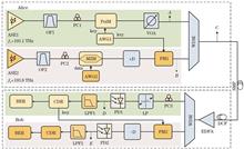
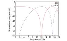
ObjectiveWith the advent of the 5G era, the continuous development of emerging applications such as cloud computing, short videos, big data, and the Internet of Things has led to a substantial increase in mobile users, resulting in growing demands for network bandwidth and transmission capabilities. However, the next generation passive optical network (NG-PON) system cannot effectively meet these demands, making it imperative to enhance NG-PON’s bandwidth supply and transmission capacity. In addition, applying direct detection (DD) technology to NG-PON can reduce system costs and implementation complexity. Traditional PON systems do not support dynamic service modes and require predefined physical connections, significantly limiting flexibility and failing to meet the demands of future broadband access networks for high dynamism, reconfigurability, and adaptability. Digital filtering multiple access (DFMA PON), on the other hand, can fulfill these requirements and effectively support 5G fronthaul services, playing a crucial role in 5G bearer networks. However, DD DFMA-PON, as a short-reach optical communication system, is highly sensitive to periodic power fading caused by fiber dispersion. As a result, dispersion becomes the primary factor limiting the transmission performance of DD DFMA-PON systems.MethodsTo address the issue of periodic power fading induced by dispersion and further improve transmission performance, we propose a parallel intensity modulation/phase modulation (IM/PM) scheme. This approach effectively mitigates the frequency-selective fading caused by dispersion. First, the complementary characteristics between IM/DD and PM/DD are analyzed theoretically. The normalized frequency responses of IM/DD and PM/DD are approximately complementary. When IM/DD experiences frequency fading, the PM response reaches its peak. Leveraging this property, the transmitter allocates subcarriers such that some carry signals modulated using IM, and others use PM modulation in the optical domain. This ensures that after direct detection via a photodetector (PD), both signals exhibit flat frequency responses. Next, the principles of LMS and Volterra adaptive filters are discussed. The Volterra series model, known for its strong adaptability, can be effectively combined with classical adaptive algorithms like LMS. This allows the model to accurately describe nonlinear systems with memory and dynamic behaviors. At the receiver, a second-order Volterra adaptive filter based on the LMS algorithm is employed to equalize and recover the received signals, further improving the system’s transmission performance.Results and DiscussionsTheoretical analysis demonstrates that IM/DD and PM/DD exhibit complementary effects (Fig. 1). Based on this property, the proposed parallel modulation achieves a flattened signal power spectrum (Fig. 4), thus mitigating frequency-selective fading. This improves signal reception sensitivity (Fig. 5). Furthermore, the Volterra filter combined with the LMS algorithm further enhances overall system performance (Fig. 6).ConclusionsIn this paper, we first theoretically analyze the complementary relationship between the frequency responses of IM and PM signals, and propose a dispersion compensation scheme for DD DFMA-PON systems based on a parallel IM/PM transmitter structure. Leveraging this property, the transmitter divides subchannels into two groups and allocates them based on the frequency response characteristics of IM and PM signals, applying different optical modulation schemes to each group to mitigate signal power fading caused by fiber dispersion. On the receiver side, a second-order Volterra adaptive filter based on the LMS algorithm is employed for equalization and recovery of each subband, further enhancing the system’s transmission performance. Simulation results demonstrate that, by exploiting the property that the sum of the frequency responses of IM and PM signals approximates one, the proposed scheme effectively compensates for dispersion-induced signal degradation. Under the conditions of 40 filter taps and a received optical power of -10 dBm, the system achieves stable transmission over 25 km, with a bit error rate below 3.8×10⁻³ and a receiver sensitivity improvement exceeding 1.5 dB. This approach offers a theoretical foundation and technical support for future optical access networks.
May. 19, 2025Vol. 45 Issue 10 1006002 (2025)
Kejun Jia, Jiaqi Che, Jiaxin Liu, and Yuqin Xian
ObjectiveVisible light communication (VLC), as a new wireless communication technology, uses light-emitting diodes (LEDs) and other visible light sources to emit light signals, which are difficult for the human eye to detect and exhibit rapid light and dark variations for information transmission. VLC addresses the shortage of spectrum resources in radio frequency (RF) communication and can also integrate with existing RF systems, allowing operation in environments prone to electromagnetic interference. However, VLC faces significant nonlinear issues, primarily caused by the LEDs. Optical orthogonal frequency division multiplexing (O-OFDM) technology can effectively mitigate intersymbol interference in VLC and enhance spectrum utilization. However, due to the peak-to-average power ratio (PAPR) characteristics of O-OFDM, LED nonlinear distortion becomes more pronounced. Therefore, suppressing LED nonlinear distortion is critical to improving the performance of the O-OFDM system and advancing VLC’s practical application. To address this, we propose a post-equalization scheme, combining the least mean square (LMS) algorithm with a cascade neighborhood rough set (NRS)-improved convolutional neural network (CNN), bidirectional long short-term memory (BiLSTM) network, and self-attention mechanism to suppress LED nonlinear distortion. This approach classifies and optimizes the constellation points at the receiving end, mitigating the LED nonlinear distortion, improving the bit error rate (BER) performance, and reducing the computational complexity of the CNN?BiLSTM?Self-Attention model. Simulation results show that the proposed algorithm effectively alleviates LED nonlinear distortion in VLC.MethodsThe binary information sequence is modulated by multi-order orthogonal amplitude modulation (M-QAM) at the transmitting end, then output as a bipolar real signal through mapping and inverse fast Fourier transform. The signal is then processed through limiting, the addition of a loop prefix, parallel-to-serial conversion, and digital-to-analog conversion, followed by DC bias to drive the LED light. The receiving photodetector (PD) receives the optical signal, converts it into an electrical signal, and undergoes a processing sequence opposite to that of the transmitting end. The frequency-domain signal from the fast Fourier transform is then input into the cascade equalizer module to balance the signal and suppress the LED nonlinear distortion. Finally, the demodulator restores the original binary information sequence. In the cascade equalization module, the first-level LMS equalization reduces the dispersion of constellation points, facilitating the second-level enhancement of the CNN?BiLSTM?Self-Attention algorithm to improve classification accuracy and further reduce computational complexity. The NRS’s powerful classification decisions and attribute reduction ability, as well as its advantages in processing continuous data, are used to divide the constellation training set data into spatial regions and formulate the corresponding classification strategy. Through classification decisions, the accuracy of data feature extraction in the CNN?BiLSTM?Self-Attention algorithm is enhanced, LED nonlinear distortion is effectively suppressed, and algorithm complexity is reduced.Results and DiscussionsMonte Carlo simulation is applied to verify the performance of the proposed CNN?BiLSTM?Self-Attention equalization algorithm. First, compared to the classification strategy of the benchmark equalization algorithm, the proposed NRS classification strategy shows higher classification accuracy under low signal-to-noise ratio (SNR) conditions. For example, under 4QAM in ACO-OFDM and DCO-OFDM systems with an SNR of 10 dB, accuracy increases by about six percent points compared to the benchmark strategy (Fig. 11). Second, by setting the indoor VLC simulation parameters and the channel link model (Table 1 and Fig. 12) as well as the model hyperparameters and training the CNN?BiLSTM?Self-Attention deep learning model (Tables 2 and 3), the CNN?BiLSTM?Self-Attention model improved by NRS achieves optimal mean square error (MSE) and BER. This happens when the model parameter combination is set to sequence number 2 (Fig. 14). In addition, the number of training rounds also reaches optimal performance, confirming that the 10% training set is appropriate (Figs. 16 and 17). Furthermore, when the PD is positioned at the center of the room [3 m, 3 m, 0.85 m], the improved LMS cascade CNN?BiLSTM?Self-Attention equalization algorithm shows better BER performance. Compared with the benchmark equalization algorithm, the proposed LMS cascade improved CNN?BiLSTM?Self-Attention algorithm significantly reduces the bit error rate. For example, in the ACO-OFDM system, an SNR gain of about 7 dB and 11 dB is achieved for 4QAM and 16QAM, respectively, at a BER of 10-4 (Fig. 18). Similarly, in the DCO-OFDM system, an SNR gain of about 7 dB and 14 dB is achieved for 4QAM and 16QAM, respectively, at a BER of 10-4 (Fig. 19). However, at the same location, the BER performance of the DCO-OFDM system is worse than that of the ACO-OFDM system due to the increased DC component, which exacerbates LED nonlinear distortion. Moreover, the proposed cascade equalization algorithm shows better BER performance even at the edge of the room [0.5 m, 0.5 m, 0.85 m]. For example, in the ACO-OFDM system, 4QAM and 16QAM achieve SNR gains of about 12 dB and 13 dB, respectively, at a BER of 10-4 (Fig. 20). However, compared to the center position, the BER at the edge is worse due to the poor channel gain. In addition, the improved LMS cascade CNN?BiLSTM?Self-Attention equalization algorithm has lower computational complexity than the traditional version (Table 5). For example, in the ACO-OFDM system with 4QAM and 16QAM, the complexity of the traditional CNN?BiLSTM?Self-Attention algorithm is 9.77×10⁸ at an SNR of 15 dB, while the improved algorithm’s complexity is 6.21×10⁷ and 6.42×10⁷, respectively. This is 1/16 of the traditional algorithm’s complexity. Under the same conditions, the traditional CNN?BiLSTM?Self-Attention algorithm for the DCO-OFDM system at an SNR of 15 dB is 3.56×10⁹, while the improved algorithm’s complexity is 2.09×10⁸ and 2.30×10⁸, respectively (Fig. 21).ConclusionsIn this paper, we propose the LMS cascade NRS-improved CNN?BiLSTM?Self-Attention equalization algorithm. It innovatively applies NRS in artificial intelligence particle computing to develop a constellation point classification strategy and enhances the CNN?BiLSTM?Self-Attention deep learning model. The CNN?BiLSTM?Self-Attention deep learning model improves constellation classification accuracy and reduces computational complexity. Simulation results demonstrate that the proposed approach outperforms the benchmark equalization algorithm, effectively suppressing LED nonlinear distortion in the VLC system, improving the system’s BER performance, and reducing computational complexity. Future studies can further enhance the robustness and stability of the proposed algorithm by investigating different channel models and dynamic nonlinear models of LEDs, thus improving its performance in more complex scenarios.
May. 20, 2025Vol. 45 Issue 10 1006003 (2025)
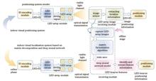
Yiyi Xu, Lifang Feng, and Zhuo Xue
ObjectiveIn recent years, with the rapid development of computer vision technology and the widespread application of deep learning algorithms, more possibilities emerge to further improve the stability and positioning accuracy of indoor positioning systems. Convolutional neural networks are very popular and effective computer vision architectures widely used. We research on an indoor positioning algorithm based on matrix factorization and deep neural networks. A dedicated dataset is constructed based on light emitting diode (LED) beacon image feature recognition, and a convolutional neural network classification model is designed. Through deep learning algorithms combined with matrix factorization for dimensionality reduction and noise reduction, accurate recognition of LED beacons is achieved, which effectively improves the recognition accuracy and positioning stability of the system model.MethodsWe combine the analysis of an indoor visual positioning system based on an LED array and conducts the following research: 1) We establish a convolutional neural network model for the indoor visual positioning system based on the LED array, construct an LED beacon dataset, analyze the fitting of the model’s training loss rate and validation loss rate, and evaluate the model’s generalization ability and recognition accuracy. 2) We propose a beacon recognition method based on matrix factorization and convolutional neural networks, which reduces the dimensionality and noise of input data through the matrix factorization algorithm, improves the accuracy of model beacon recognition, and enhances the positioning accuracy and stability of the system. Further, we quantify the parameter count (parameters) and floating-point operations (FLOPs) of the model and combine theoretical calculations with hardware measurement data to perform a complexity analysis, providing a theoretical basis for deploying resource-constrained mobile devices. 3) According to the indoor positioning scheme, we deploy LED beacons in actual scenarios to measure and analyze the beacon recognition accuracy and positioning accuracy of the positioning system before and after combining it with a convolutional neural network model based on the matrix factorization algorithm.Results and DiscussionsThe actual testing environment in this article is a 7 m×5 m×3 m room, as shown in Fig. 3, and the relevant experimental parameters are listed in the table. The deployment spacing of the LED beacons is set to 2 m. We aim to improve the recognition accuracy of the beacons through deep neural network models, thereby enhancing the positioning accuracy of the system. Therefore, it is necessary to measure the recognition accuracy and positioning accuracy, which will be verified through the following two experiments. Experiment 1: to measure the recognition accuracy of the model for LED beacons, an LED beacon dataset is constructed. The number of datasets is shown in Table 2. To further enrich the complexity and diversity of the dataset and to simulate lighting changes, rainy and foggy weather, and dynamic interference, some example images are shown in Fig. 4. Based on the fixed size of the dataset, the model’s hierarchical parameter quantity and FLOPs quantity are calculated. The specific results are shown in Table 3. It can be seen that the total parameter quantity of the model is 1.55×10⁵, and the single sample inference calculation quantity is 2.8×10⁵ FLOPs. By training and learning on the dataset, both the training loss and validation loss rapidly decrease in the first three rounds of 20 training epochs, then stabilize, which indicates that the model has a good fit on the training data and good generalization ability on the validation set, as shown in Fig. 6, with recognition accuracy ranging from 99.33% to 100%. Figure 7 shows the analysis of the computational complexity of the model. The fully connected layer accounts for 92.4% of the total computational complexity, which indicates that this layer is the computational bottleneck of the model. In the future, it can be further optimized by replacing it with global average pooling. The trend of the computational complexity of the training and validation sets with respect to epochs shows that, due to the fixed dataset size, the computational complexity increases linearly, consistent with theoretical analysis. Experiment 2: to verify the positioning accuracy of fixed positions within the recognition range, positioning accuracy tests are conducted at different positions within the recognition range of a single LED beacon. The test results are shown in Fig. 8. The overall average positioning error is 6.12 cm, which is basically consistent with the theoretical positioning error of the algorithm. The positioning accuracy within the recognition range of the LED beacon is not affected. Further testing of the positioning accuracy is conducted by deploying the receiving end on the robot, which allows the robot to move at a constant speed in the experimental scene and collect positioning data. The number of successful positioning attempts is counted, and the deviation distance from the route is used as the positioning error. The cumulative distribution function (CDF) generated is shown in Fig. 9. After 1000 positioning attempts, the number of successful positioning attempts ranges from 956 to 985, with positioning errors below 6 cm exceeding 80%, and below 10 cm almost reaching 100%. Compared with the pre-application recognition method positioning system, the positioning accuracy has improved by 22.64%, which proves that the recognition method based on matrix factorization and the deep neural network model proposed in this paper has a certain effect on improving the positioning performance of indoor positioning systems.ConclusionsWe propose a deep neural network recognition algorithm based on matrix factorization optimization to address the problems of low beacon recognition accuracy and poor stability in LED array indoor positioning systems. By constructing a convolutional neural network (CNN) model based on non-negative matrix factorization (NMF), while retaining the spatial feature extraction ability of CNNs, and combining it with the sparse characteristics of LED beacons, NMF is used to achieve data dimensionality reduction and noise suppression. The experiment shows that the model achieves a recognition accuracy of 99.77% on the expanded multi-interference dataset, which is 8.50 percentage points higher than the comparison system. The average positioning error of this method is 6.12 cm, which is 22.64% better than the positioning accuracy of the comparison system. This method provides a new technical path for high-precision visible light positioning. The method proposed in this article has broad application potential. In smart home environments, it can achieve precise indoor positioning for automatic lighting control, energy management, and intelligent security systems. In industrial automation, this method can enhance robot navigation, asset tracking, and workspace safety by achieving real-time, high-precision positioning. In addition, in the field of healthcare, this method can be used for patient monitoring, elderly care, and indoor navigation in hospitals. Based on the research in this article, a potential future direction for research is enhancing the robustness of algorithms in dynamic and complex environments, which may require multi-sensor fusion of multi-source information. Additionally, exploring other machine learning or deep learning algorithms may further improve the accuracy and adaptability of recognition. At the same time, reducing algorithm complexity and achieving model lightweight, as well as testing algorithms in different real-world scenarios, are also crucial for their practical deployment. Overall, we lay a foundation for more reliable and secure LED-based indoor positioning systems, opening up new possibilities for advanced location-based services.
May. 19, 2025Vol. 45 Issue 10 1010001 (2025)
Yu Han, Zhoujie Wu, and Qican Zhang
ObjectiveIn temporal phase unwrapping algorithms for fringe projection measurement technology, the accuracy of phase order decoding plays a decisive role in the successful recovery of the object’s height. The methods for obtaining phase orders are mainly divided into two categories. One approach involves projecting multi-frequency phase-shifted fringes, calculating the wrapped phases corresponding to fringes with different periods, and then solving the phase order according to the periodic relationship between the projected fringes. The other approach involves projecting a series of multi-level gray fringes or black-and-white binary fringes, encoding the period information of phase-shifted fringes at a single frequency, and obtaining the phase order after decoding according to established rules. Inspired by the above two methods, we propose directly dividing the wrapped phase values, calculated from multi-frequency phase-shifted fringes, into binary values according to different thresholds, and then obtaining different coding words, which are used to mark the orders of the phase-shifted fringes to reconstruct the continuous phase. Existing methods proposed by researchers, which rely on a single threshold for binarizing the wrapped phase to extract phase orders, are prone to errors in phase order jump areas. In this paper, corresponding threshold division results for the two methods are proposed to meet the complementary Gray code coding and decoding strategy, which can effectively avoid the error problem at the order jump, obtain correct phase order information, and flexibly realize different algorithms for phase unwrapping.MethodsDifferent binary patterns can be obtained by dividing the wrapped phase values obtained from multi-frequency fringes with different thresholds. Considering that the Gray code encoding methods are complementary at the coding word transitions, and offer higher fault tolerance and stronger anti-noise performance, the idea of Gray code is introduced. By adjusting the threshold of the wrapped phase, a pattern sequence that meets the coding and decoding strategy of the complementary Gray code method can be directly constructed. This sequence can effectively avoid jump errors and provide correct order information after decoding. To reduce the number of multi-frequency phase-shifted fringes that need to be projected in one measurement, we further propose a method of projecting only bi-frequency phase-shifted fringes. The single-period phase-shifted fringes are used to generate the pattern corresponding to the complementary Gray code method, thus enabling accurate reconstruction of the three-dimensional surface shape. This method significantly reduces the number of projected patterns and greatly improves the efficiency and usability of the temporal phase unwrapping algorithm based on multi-frequency phase binarization.Results and DiscussionsIn this paper, we propose two new methods successively: the bi-threshold binarization for multi-frequency fringes method (MFBT) and the multi-threshold binarization for bi-frequency fringes method (BFMT). Both methods acquire Gray code sequence patterns and calculate the fringe orders through decoding based on the complementary Gray code method, thus avoiding errors in fringe order jumps in principle. Among them, the BFMT offers more advantages in terms of phase unwrapping efficiency and performance, with the following specific manifestations. In terms of efficiency, compared with the MFBT also proposed in this paper, the number of fringes required to recover the accurate phase is significantly reduced. Furthermore, compared with the traditional complementary Gray code method, it still has an advantage in the number of projected fringes under certain specific conditions. In terms of robustness, compared with the phase unwrapping algorithm in which the Gray code pattern assists phase shifting, the BFMT only requires projecting a single type of phase-shifted fringe pattern to achieve phase unwrapping with the assistance of binary-coded patterns. This effectively solves the problem of inconsistent defocus requirements in the projection system, which is common in the traditional Gray code method. Compared with the traditional bi-frequency phase unwrapping method, the BFMT adopts the encoding and decoding strategy of the complementary Gray code method. When the frequency difference between the bi-frequency fringes is large, the Gray code patterns are less sensitive to frequency changes and exhibit stronger anti-noise performance. Therefore, for the same number of projected patterns, the BFMT shows stronger robustness.ConclusionsCombining the two categories of methods for calculating phase orders in temporal phase unwrapping algorithms, we propose two temporal phase unwrapping algorithms based on multi-frequency phase binarization: MFBT and BFMT. Both methods adopt the idea of complementary Gray code, which can effectively avoid the jump errors caused by using the single-threshold binarization method previously proposed by researchers. Both simulation and actual experiments verify the effectiveness of the proposed methods, enhancing the practicality of multi-frequency fringe projection three-dimensional measurement technology. In addition, the BFMT has an advantage in unwrapping efficiency and offers higher practical value.
May. 16, 2025Vol. 45 Issue 10 1011001 (2025)
Zhihui Ding, Fengxu Guo, Yingli Liu, Haifeng Li, and Rengmao Wu
ObjectiveAccurate phase detection is crucial for optical measurement precision and sample thickness reconstruction, especially for weakly absorbing or transparent specimens. Traditional bright-field microscopy lacks phase sensitivity, leading to phase imaging techniques like wave-front sensing, iterative phase retrieval (IPR), and digital holography. IPR is widely used due to its simple setup and robustness. However, multi-plane phase retrieval (MPR) requires precise alignment, which is challenging. Existing solutions include optical path modifications, which increase system complexity and cost, and image registration techniques, which neglect tilt misalignment. These limitations affect phase reconstruction accuracy and require additional manual adjustments. Therefore, it is necessary to propose a digital automated strategy for precise calibration of MPR.MethodsTo address these issues, we propose an adaptive joint calibration-based multi-plane phase retrieval (ACMPR) technique to develop a low-cost, high-performance phase imaging system, eliminating the need for precise optical alignment or additional markers. The proposed method integrates auto-focusing, cross-correlation calibration, and tilted plane calibration to compensate for displacement errors and tilt errors digitally. This significantly reduces reliance on complex experimental setups and precision mechanical adjustments, improving the system’s robustness and flexibility. In the calibration stage, we use the cross-correction method to correct the displacement error. Then the Tamura of gradient (ToG) method is utilized to evaluate the tilt error and diffraction distance of the first image. In this way, a precise digital calibration of each parameter in the lensfree system can be achieved, since the optimal reconstruction plane has been determined. In the reconstruction stage, we employ a multi-plane phase retrieval (total variation-based adaptive phase retrieval, TV-APR) algorithm that incorporates spatial weighting and total variation (TV) regularization to accelerate the iterative convergence process. Additionally, we adopt Bluestein-based angular spectrum propagation, which enhances computational efficiency by enabling fast diffraction calculations. These techniques collectively ensure high-quality phase retrieval while maintaining computational efficiency.Results and DiscussionsThe ACMPR method effectively compensates for displacement and tilt errors in multi-plane diffraction imaging, as confirmed by simulation and experimental results. Unlike traditional methods such as adaptive cascade calibrated (ACC) method, which only correct displacement errors, ACMPR simultaneously calibrates both displacement and tilt errors, ensuring precise image reconstruction. Cross-correlation-based registration eliminates displacement errors, while the ToG method accurately estimates diffraction distances, resulting in optimal system alignment. In resolution chart reconstruction experiments as shown in Fig. 7, ACMPR achieves an ultimate resolution of 3.2 μm, successfully resolving the seventh group’s second line pair. In contrast, the ACC method, affected by tilt-induced defocus, reduces resolution to approximately 4.4 μm. By correcting both errors, ACMPR enables the diffraction imaging system to reach its theoretical resolution limit, significantly enhancing image quality. Additionally, ACMPR proves robust under complex conditions, as demonstrated in biological sample reconstructions shown in Figs. 8 and 9. It successfully restores fine details in pancreatic cancer tissue and osteosarcoma cell slices, whereas the traditional methods suffer from uncorrected tilt errors, leading to image distortion. Another advantage of ACMPR is its effectiveness in large-error scenarios, maintaining high-quality reconstruction even with displacement errors up to 10 pixel and tilt errors up to 20°. The high structure similarity index measure (SSIM) and normalized cross-correlation (NCC) evaluation values can also indicate quantitatively the effectiveness of ACMPR as shown in Table 1. Hence ACMPR is well-suited for phase imaging, especially in the portable and miniaturized applications. ACMPR is also ideal for label-free imaging as it can successfully reconstruct the fine phase structures. It indicates that ACMPR outperforms conventional calibration techniques by precisely compensating for displacement and tilt errors. Its accuracy, robustness, and adaptability make it a powerful tool for computational imaging, biomedical imaging, and diffraction-based optical systems, achieving high-resolution, distortion-free reconstructions in challenging imaging environments.ConclusionsACMPR method can address the alignment and calibration challenges in multi-plane phase retrieval by providing a fully digital calibration and reconstruction approach. It utilizes cross-correlation calibration to correct displacement errors and an autofocusing algorithm to simultaneously calibrate tilt errors and diffraction distances. Once the system is accurately calibrated, the TV-APR algorithm is applied for iterative recovery of the complex amplitude of the object plane, achieving phase reconstruction at the theoretical resolution limit. To optimize ACMPR’s calibration performance, various autofocusing and image-matching algorithms are compared, ensuring the best calibration accuracy. The method is further benchmarked against the APR algorithm based on the in-line assumption and the ACC algorithm with displacement correction, demonstrating its superiority in handling systematic errors. Experimental results show that ACMPR effectively reconstructs object-plane information across various sample types and error conditions, whereas conventional methods suffer from defocus blurring and other inaccuracies. Unlike traditional multi-plane approaches, ACMPR maintains robust performance under different misalignment conditions, proving its effectiveness and adaptability. It provides a promising digital strategy for high-resolution phase retrieval, computational light-field imaging, and the miniaturization of optical microscopy systems. By offering an automated, precise calibration framework, ACMPR enables enhanced imaging performance and extends the applicability of phase retrieval techniques in next-generation optical systems.
May. 16, 2025Vol. 45 Issue 10 1011002 (2025)
Yingran Tong, Wanqin Fu, Mingxu Piao, Qun Niu, Yuanming Zhao, Xian Zhang, Huitian Zou, Yichen Lou, Haoran Wang, and Zhiming Hu
ObjectiveWith advancements in technology, the miniaturization and lightweight design of imaging systems have become inevitable trends. Traditional infrared systems often rely on refractive, reflective, or catadioptric structures, which involve numerous optical components, resulting in larger volumes and more complex configurations. While current infrared cooled optical systems utilize mirrors and other optical elements to fold the optical path, thereby improving performance without increasing system length, miniaturized designs still require multiple optical elements and complex surface profiles. Single-element imaging technologies, such as metasurfaces or diffractive lenses, are not yet applicable to cooled infrared systems. Additionally, the placement of the cold stop in traditional systems complicates the optical structure and introduces narcissus effects that degrade imaging quality.To address these challenges, this paper proposes a cooled monolithic annular aperture folded imaging (AAFI) optical system. This design leverages the unique structure of annular aperture systems, which integrate multiple concentric reflective rings on a single substrate. Light enters through the outermost annular aperture and is focused onto the central image plane via concentric reflective rings. The system adopts a four-reflection configuration to optimize performance while minimizing complexity.MethodsThe annular aperture system is characterized by its integrated design, where multiple concentric reflective rings are mounted on a single substrate. Light enters through the outermost annular aperture and is focused onto the central image plane via a series of reflective rings. In cooled AAFI systems, the cold stop inherently blocks marginal rays, necessitating coordinated optimization of key parameters such as back focal length (Lcold), cold stop diameter (dcold), system focal length (f), and entrance pupil diameter (D). These parameters—back focal length, obscuration ratio, and entrance pupil diameter—are critical to designing efficient cooled AAFI systems. This paper derives quantitative relationships among these parameters (Fig. 2) and proposes a design method for cooled infrared AAFI systems.Stray light, a significant threat to imaging fidelity in compact optical systems, is addressed through a specialized baffle structure (Fig. 3). Designed based on the geometry of the annular aperture lens and the distribution of stray light rays, this structure effectively mitigates stray light interference.Results and DiscussionsThe finalized imaging system features an outer diameter of 51 mm, an effective clear aperture of 38 mm, a focal length of 102 mm, and a total optical element length of 11.2 mm, resulting in a ratio of total optical length to system focal length of 0.11. Detailed parameters are provided in Tables 2 and 3, with the optical layout illustrated in Fig. 5. Analysis confirms that the absolute YNI values for all surfaces exceed 1, effectively suppressing narcissus energy (Table 4). Optical distortion remains below 1.5%, and the modulation transfer function (MTF) curves exceed 0.27 at 21 lp/mm across all fields of view (Fig. 7). The longitudinal chromatic focal shift curve (Fig. 9) shows a focal plane shift of 16.4 μm across the design wavelength range, which is negligible in practical imaging, confirming minimal chromatic aberration.Given the sensitivity of annular aperture systems to ambient temperature variations, thermal performance analysis is critical to ensure imaging stability. The single-element design introduces defocus under temperature changes, which can be compensated mechanically. The linear relationship between detector compensation distance and temperature variation is shown in Fig. 10.ConclusionsThis paper proposes a cooled infrared monolithic AAFI optical system based on the unique structure of annular aperture imaging systems. Theoretical derivations establish relationships between key parameters such as entrance pupil diameter, back focal length, field of view, and baffle ratio. A design method for cooled infrared AAFI systems is presented, and an example system is designed and validated. Results demonstrate excellent imaging performance, with MTF curves exceeding 0.27 at 21 lp/mm across all fields of view within the 3.7?4.8 μm wavelength range. A baffle tailored to the structural characteristics of the annular aperture system is designed, and iterative optimization reduces the baffle length by 34%. Compared to the initial system without a baffle, the PST with a single-layer baffle decreases by 2?3 orders of magnitude in the 4°?24° range and by 1 order of magnitude in the 24°?30° range. The compact optical structure of the proposed system offers a novel approach for the integration and miniaturization of cooled infrared optical systems.
May. 14, 2025Vol. 45 Issue 10 1011003 (2025)
Zhaorui Hu, Linjun Gu, Jiacheng Zhu, and Weimin Shen
ObjectiveIn the medical field, surgery remains the cornerstone of treatment for most diseases. The success of surgical procedures critically depends on the clear visualization of pathological structures after dissection. Surgical microscopes, offering adjustable magnification, bright illumination, and high-definition operative views, have become indispensable tools in microsurgery. In recent years, increasing demands for broader fields of view, finer imaging precision, and improved ergonomics have led to higher requirements for zoom ratio and compactness in optical systems. These advancements primarily rely on their core component: the afocal zoom system. Despite significant progress, a persistent trade-off exists between zoom ratio and system length, making it difficult to achieve both high magnification and compact size. Most current systems achieve only a 6× zoom ratio within an 80 mm structure, failing to optimize both simultaneously. Therefore, addressing this trade-off is a critical step toward developing high-performance surgical microscopes with significant clinical value.MethodsTo meet the growing demand for high zoom ratios in surgical microscopes, we propose a design methodology for a compact, high-zoom-ratio afocal zoom system. First, an appropriate optical configuration is selected based on system specifications. Paraxial ray tracing of the first and second principal rays is used to derive the vignetting coefficient as a function of system apertures and component focal powers, revealing the relationship between vignetting and focal power distribution. This yields an initial optical layout with minimized vignetting. Subsequently, virtual stops and lens apertures are optimized to further control vignetting. Material selection and system layout are refined to correct aberrations, resulting in a system with a 20 mm clear aperture, 80 mm total length, and a continuous 10× zoom range (0.4×?4.0×). Finally, each lens barrel is aligned independently using optical design tolerances to ensure coaxial alignment and MTF compliance. Compensation lenses in the dual-barrel system are adjusted via eccentric ring rotation, leveraging optical axis offset to align binocular optical axes at infinity, meeting the imaging requirements of surgical applications.Results and DiscussionsBased on the proposed design method, a compact, mechanically compensated afocal zoom system with a high zoom ratio is designed. The system features an overall length of 80 mm and a maximum aperture of 20 mm, and adopts a ‘+--+’ configuration comprising five lens groups. Among these, the zoom group consists of a triple-cemented lens assembly with a negative optical focal length. The overall design achieves a compact and high-performance optical layout (Fig. 8). Evaluation of the image quality of the system yields the following results: the lens cam curve exhibits a smooth trend without inflection points (Fig. 10). Relative illumination is 54% at 1× magnification and exceeds 90% at higher magnifications (Fig. 7). The modulation transfer function (MTF) remains above 0.2 at 0.4×, 1.3×, and 4.0× magnifications, corresponding to full-field average values of 20, 60, and 110 lp/mm, respectively (Fig. 11). Finally, tolerance and optical axis sensitivity analyses confirm the system’s high feasibility (Table 3, Fig. 13, and Table 4).ConclusionsIn this paper, we propose an afocal zoom optical system for surgical microscopes, along with a method for determining focal length distribution and initial layout based on Gaussian optics. Through detailed analysis of the relationship between vignetting and optical power allocation, as well as optimization of the virtual diaphragm and lens aperture, the design effectively controls vignetting under structural length constraints. The resulting afocal zoom system achieves a tenfold continuous zoom range of 0.4× to 4.0×, with a maximum aperture of 20 mm and a total length of 80 mm. This system demonstrates excellent imaging performance, with a smooth zoom curve free of inflection points, ensuring both engineering feasibility and suitability for practical surgical microscope applications.
May. 19, 2025Vol. 45 Issue 10 1011004 (2025)
Pengfei Zhou, Yuyang Zhao, Chenghao Jiang, Tianpeng Xie, Yan Jiang, Zhonghe Liu, and Jingguo Zhu
ObjectiveLiDAR has been widely applied in fields such as aerospace, autonomous driving, 3D modeling, and environmental monitoring. However, traditional LiDAR systems face significant challenges in detecting weak signals under conditions such as haze, sandstorms, underwater environments, and long-distance scenarios. To meet the demand for weak-signal detection capabilities, single-photon LiDAR based on single-photon avalanche diodes (SPADs) and time-correlated single-photon counting (TCSPC) technology can enhance detection sensitivity to the photon level. This significant improvement in light signal utilization forms the foundation for high-precision 3D reconstruction in weak-signal environments. However, in practical applications, single-photon LiDAR struggles to accumulate enough signal photons due to limitations in laser power and imaging time. In addition, ambient light and dark counts from SPAD detectors introduce significant noise into the measurement data. Photon-counting histograms with low signal photon counts and low signal-to-background ratios present significant challenges to single-photon imaging algorithms. Moreover, existing single-photon imaging algorithms often fail to fully account for the spatiotemporal and feature correlations in the data, neglecting the interrelationships among time, space, and channels. To address these issues, we propose an attention-guided multi-scale fusion neural network (AMSF-Net), based on the spatiotemporal and feature correlations of photon-counting histograms, designed for single-photon imaging from highly noisy measurement data.MethodsAMSF-Net consists of three main components: the feature extraction module, the feature integration module, and the reconstruction module. In the feature extraction module, AMSF-Net alternates between standard 3D convolutions and dilated 3D convolutions along two parallel branches to extract different low-frequency features. Considering the temporal sparsity of photon-counting histogram data, a downsampling operation is introduced along the temporal dimension in the feature space to accelerate model training and expand the receptive field of the backbone network. In the feature integration module, we propose an improved multi-scale architecture. This structure adopts a strategy of low temporal resolution but high feature channel count, enhancing the model’s feature extraction capability. Due to the increased number of feature channels in the multi-scale structure, an attention-guided dilated dense fusion (ADDF) module is designed. By incorporating channel attention enhancement, this module eliminates potential redundancy introduced by the higher channel count. When combined with the multi-scale network, it effectively leverages temporal, spatial, and inter-channel correlations, significantly improving the network’s reconstruction performance. In the reconstruction module, transposed convolution is used to restore the spatial and temporal dimensions. Finally, the Softargmax layer estimates the time-of-flight of the laser pulses to generate the final depth map. In addition, we employ a hybrid loss function, combining Kullback-Leibler (KL) divergence and total variation (TV) regularization, to further enhance reconstruction quality.Results and DiscussionsBased on the single-photon LiDAR imaging model, photon-counting histograms are generated from the NYU v2 dataset for neural network training and the proposed algorithm is validated on simulated datasets. Qualitative experimental results demonstrate that the proposed model reconstructs depth maps with clear details under various signal-to-background ratios (SBRs), outperforming other algorithms. In quantitative comparisons, AMSF-Net achieves the best performance among all competing methods, attaining the lowest root mean square error (RMSE) and the highest structural similarity index (SSIM). When the SBR is 2∶10 or 2∶50 (where the error between the ground truth and predicted depth maps is less than 1.5%), AMSF-Net achieves an accuracy exceeding 92%. Even under an extremely low SBR of 0.02, AMSF-Net still maintains high-precision reconstruction with an RMSE below 0.05 m and accuracy above 90%. More importantly, AMSF-Net exhibits stronger robustness against noise interference. As noise levels increase, all algorithms experience performance degradation, but AMSF-Net shows the smallest decline across all metrics. Particularly under the extreme condition with SBR of 1∶100, AMSF-Net reduces the RMSE by 60% compared to the second-best method and improves accuracy by 11%, while remaining the only approach with an accuracy exceeding 80%. In addition, the proposed method demonstrates excellent imaging performance on real-world data, confirming its practical potential in single-photon imaging. Through ablation studies, the critical roles of the multi-scale architecture, ADDF module, and CBAM, as well as the effectiveness of the hybrid loss function (combining KL divergence and TV regularization), are verified in improving reconstruction accuracy.ConclusionsTo address the challenge of reconstructing high-quality depth images from low-signal, high-noise photon-counting histogram data, we propose AMSF-Net for single-photon depth reconstruction. Specifically, AMSF-Net effectively enhances network performance by reducing temporal dimensionality while appropriately increasing feature channel count. However, the increased feature channels in the multi-scale structure may introduce redundant information. To mitigate this, we integrate the CBAM attention mechanism into an expanded dense fusion module, constructing an ADDF module. This module enhances the network’s ability to extract critical features while significantly improving the accuracy of edge information in the spatiotemporal domain and feature information in the channel domain. Furthermore, a hybrid loss function combining KL divergence and TV regularization ensures reconstruction precision. Experiments with simulated datasets show that even under an extremely low SBR of 0.02, the proposed network achieves high-precision reconstruction with an RMSE below 0.05 m, confirming its robustness and effectiveness in high-noise environments. In addition, the method demonstrates excellent imaging performance on real-world data, validating its generalization capability.
May. 19, 2025Vol. 45 Issue 10 1011005 (2025)
Lang Li, Zhongsheng Jiang, Zhouchang Hu, Shuang Yang, Yuquan Tang, Xingrong Jiang, Miao Sun, Zhirong Zhang, Xiaoxia Qiu, Shuai Wang, and Chunfeng Hu
ObjectivePipeline leakage poses a significant threat to critical infrastructure, including energy transportation and urban water supply systems. It creates serious safety hazards and results in substantial economic losses. While traditional detection methods like drone inspections, acoustic sensing, and infrared thermography are effective for regional monitoring, they face limitations in large-scale, complex environments, such as low efficiency, poor real-time performance, and limited accuracy. Distributed acoustic sensing (DAS) technology, which uses optical fibers to capture and analyze pipeline vibrations in real time, has emerged as a promising solution for large-scale monitoring. However, research on efficient DAS algorithms tailored for multi-scenario and multi-medium environments remains scarce, and existing algorithms require improvement in feature extraction and global relationship modeling. To address these challenges, this paper proposes a hybrid CNN-Transformer architecture designed to enhance the classification accuracy and efficiency of pipeline leakage signals across diverse scenarios.MethodsThe proposed CNN-Transformer model integrates the local feature extraction capabilities of CNNs with the global dependency modeling advantages of Transformers. DAS signals are first transformed into spectrograms via short-time Fourier transform (STFT) and processed by a spectrum feature extraction module. Concurrently, the signals are fed into a multi-scale feature extraction module, which includes a coarse-fine granularity submodule and a Transformer module. The submodule extracts fine-scale features (capturing local changes and high-frequency patterns) and coarse-scale features (representing broader trends and low-frequency information). These multi-scale features are then refined in the Transformer module to capture global dependencies and semantic relationships, enabling the model to deeply understand the intrinsic patterns of the signals. Finally, the combined feature vectors are passed into a classification module, where linear transformations further refine the features for accurate leakage identification.Results and DiscussionsAblation experiments (Fig. 6) demonstrate that incorporating the Transformer module significantly enhances the model’s ability to capture global dependencies. Multi-layer Transformer integration deepens hierarchical feature extraction and boosts network representation capabilities. Comparative experiments with traditional models [Fig. 7(b)] show that the proposed model achieves an average accuracy of 97.466% across ten validation tests, outperforming classical models with minimal accuracy fluctuations, thus proving its robustness. Performance metrics analysis (Fig. 8) confirms excellent precision, recall, and F1-score results, validating the model’s structural effectiveness. In multi-scenario comparisons [Fig. 9(a)], the proposed model achieves an average false positive rate of 0.3% across seven industrial monitoring scenarios, a 42% improvement over baseline models. Although the Transformer module increases inference latency to 4.3 ms, this still meets industrial real-time requirements. t-SNE dimensionality reduction analysis (Fig. 10) reveals that post-extraction features form tightly clustered, well-separated categories in the reduced space, highlighting the model’s effectiveness in capturing critical signal distinctions.ConclusionsThe proposed CNN-Transformer architecture offers an efficient and reliable solution for DAS-based pipeline leakage monitoring. By combining spectrum feature extraction with global dependency modeling, the model achieves high classification accuracy across diverse scenarios (underground, underwater, aerial) and media types (liquid, gas). This study advances the field of DAS pipeline leakage signal recognition and provides new algorithmic insights. Future work will focus on expanding datasets to cover more leakage scenarios and integrating advanced algorithms to further enhance performance and applicability.
May. 14, 2025Vol. 45 Issue 10 1012001 (2025)
Yiqi Zhu, Shijie Xin, Xing Chen, Jian Song, and Mingjian Gu
ObjectiveThe accurate calibration of infrared absolute radiance payloads is crucial for high-precision space-based measurement, especially for climate monitoring and environmental research. The emissivity of blackbody sources must be carefully determined to ensure the accuracy of infrared radiance measurement from space-based instruments. However, this process faces challenges due to various factors that contribute to measurement uncertainty. In particular, the heated halo structure serving as a key component in infrared radiometric calibration introduces additional complexity in the uncertainty estimation of emissivity measurement. We propose an approach to assessing the uncertainty in the emissivity measurement of the blackbody within an infrared absolute radiance payload based on a heated halo structure. The goal is to optimize the measurement accuracy by identifying key error factors and assessing their propagation via the system.MethodsThe measurement system employs a heated halo structure, consisting of an annular thermal radiation source surrounding a blackbody target. The halo is heated to a specific temperature, creating a controlled radiative environment that interacts with the blackbody’s thermal radiation. The blackbody emissivity is determined by analyzing the radiation reflected by the blackbody and reaching a spectrometer, which measures the infrared spectrum emitted from the blackbody. The system is designed to measure the absolute radiance emitted by the blackbody, which is influenced by factors such as temperature variations, spectral sensitivity of the measurement equipment, and geometrical configurations. Meanwhile, an error propagation model is developed to quantify the emissivity measurement uncertainty. The model incorporates various sources of uncertainty, such as the temperature uncertainties of both the blackbody and the heated halo, the spectral response of the spectrometer, and geometrical factors affecting radiation collection. We conduct a simulation to evaluate how each source of uncertainty propagates during the measurement process. By simulating the uncertainties associated with the temperature of the blackbody and halo, as well as the spectrometer’s precision, the model assesses the effect of each factor on the final measurement uncertainty.Results and DiscussionsSimulation results indicate that several key factors significantly influence the emissivity measurement uncertainty. Among these factors, the temperature uncertainties of the blackbody and heated halo, as well as the spectral sensitivity of the spectrometer, emerge as the most influential factors. The temperature of the blackbody is critical as any fluctuation in its temperature directly affects the emitted radiance. Similarly, uncertainties in the heated halo’s temperature introduce variability in the radiative environment, which can affect the overall measurement precision. Spectrometer sensitivity also plays a crucial role in the uncertainty assessment. The spectrometer’s ability to resolve fine variations in the emitted spectrum is central to accurate radiance measurement. A high-precision spectrometer with low sensitivity errors is essential for minimizing the measurement uncertainty. Additionally, the distance between the blackbody and the heated halo, and the geometric alignment of the components are factors to be optimized for improved measurement accuracy. One of the most critical findings of the simulation is that minimizing the temperature difference between the high and low-temperature states of the heated halo can significantly reduce measurement uncertainty. Further analysis of the system’s geometry reveals that the relative positioning of the blackbody and heated halo affects the radiative exchange between the components. Optimizing the distance between the blackbody and the halo is crucial for minimizing radiative interference and achieving more accurate emissivity measurements. The results also highlight the importance of careful calibration of the spectrometers. The precision of the spectrometer in measuring infrared radiation is critical, as even small errors in spectral measurement can propagate through the system and result in significant uncertainty in emissivity calculation. Fig. 7 presents the combined effects of all uncertainty sources, showing the relative contributions of spectrometer sensitivity and temperature uncertainties. It illustrates the significant influence of temperature uncertainties of the blackbody and the spectral sensitivity of the spectrometer. Meanwhile, Fig. 8 reveals how spectral sensitivity errors affect the final uncertainty, with larger errors in spectral measurement causing higher uncertainty in emissivity determination. Fig. 9 further examines the influence of thermal control on the measurement process. The data suggests that maintaining a stable temperature environment for the blackbody minimizes fluctuations in the measurement, thus improving the emissivity result accuracy. In the conditions allowed by technology, efforts should be made to minimize the temperature uncertainty of the blackbody as much as possible. These results demonstrate that optimizing the spectrometer’s sensitivity and stabilizing the system’s thermal environment are the most effective ways to reduce the emissivity measurement uncertainty.ConclusionsWe provide a comprehensive uncertainty model for measuring the emissivity of blackbody sources in infrared absolute radiance payloads based on a heated halo structure. The findings emphasize the importance of considering multiple sources of uncertainty, including temperature fluctuations, spectrometer sensitivity, and geometrical configurations. By optimizing these factors, significant improvements in measurement accuracy can be achieved. The research results provide essential insights for the design and calibration of high-precision infrared absolute radiance payloads, offering guidance for future space-based climate monitoring missions. The developed model serves as a foundation for enhancing the traceability and reliability of infrared radiance measurements, contributing to the development of more accurate and standardized space-based radiometric systems.
May. 16, 2025Vol. 45 Issue 10 1012002 (2025)
Yuchen Zhao, Yeping Wang, Zhan Hu, Yurong Pu, and Xiaoli Xi
ObjectiveValley photonic crystal (VPhC) slow-light waveguides can achieve robust optical transmission even in the presence of structural defects or sharp corners. However, the normalized delay bandwidth product (NDBP) of VPhC slow-light waveguides is still limited at present. Therefore, we propose a broadband low-dispersion VPhC slow-light waveguide designed by employing machine learning technique, providing references for the design of broadband low-dispersion VPhC slow-light waveguides and machine learning-based optimization of integrated photonic devices.MethodsWe take the bearded interface VPhC slow-light waveguide as the research object and adopt the machine learning method to optimize the size of equilateral triangular air holes on both sides of the interface, so as to realize the design of broadband low-dispersion VPhC slow-light waveguide. Firstly, two-dimensional plane wave expansion (PWE) is utilized to simulate the dispersion curve of the topological boundary state, with the influence of the size of air holes at different distances from the interface on the broadband low-dispersion slow-light characteristics of the topological boundary state discussed. Then, the NDBP values of the VPhC waveguides with different air hole sizes near the interface are calculated by employing the histogram of the group indices of the topological boundary states, with the database established. The samples with multi-mode and non-significant slow-light effects are marked. On this basis, a series classification regression neural network is trained to predict the NDBP of VPhC waveguides with significant slow-light characteristics (group index≥20). Finally, this forward prediction network is combined with the particle swarm optimization (PSO) algorithm, and the VPhC slow-light waveguide structure with NDBP up to 0.356 is designed by optimizing the size of the three rows of air holes near both sides of the interface.Results and DiscussionsTwo-dimensional PWE is adopted to simulate the dispersion curve of the topological boundary state, and the influence of the size of air holes at different distances from the interface on the broadband low-dispersion slow-light characteristics of topological boundary state is discussed (Fig. 3). By conducting the analysis, the variation range of air holes is determined, and 1287 VPhC waveguide samples with different size of air holes near the interface are collected for the training of the sequence classification neural network (Table 1). By optimizing the neural network structure, the accuracy of neural network classification and prediction is further improved, and the mean square error is reduced (Fig. 4). Then PSO is combined with the trained neural network (Fig. 4) to optimize the structure corresponding to the maximum NDBP value of 0.3555. The optimization results are verified by two-dimensional PWE, and the calculated NDBP is 0.3654, and the full-wave simulation verifies the robust transmission of the optimized topological boundary state in the straight and Z-type waveguides, with the transmission of the pulse signal in the waveguide calculated (Fig. 5). It is improved compared with the reported VPhC slow-light waveguide NDBP (Table 2). The influence of manufacturing error on the performance of the optimized waveguide is analyzed, and the results show that the error will result in a relative small reduction of NDBP (Fig. 6).ConclusionsBy taking the VPhC waveguide as the main research object, we study the design method of broadband low-dispersion slow-light waveguide based on machine learning. Firstly, the dispersion curves of the boundary states of the bearded interface configuration VPhC waveguide are simulated by the two-dimensional PWE method, and the influence of the size of equilateral triangular air holes near the interface on the broadband low-dispersion slow-light characteristics of the topological boundary state is analyzed. Then, the forward prediction neural network with a series classification regression structure is trained to select the VPhC waveguide with significant slow-light characteristics (group index≥20), with the relationship between NDBP and the size of air holes near the interface modeled. Finally, the PSO algorithm is employed to drive the network, and the size of the corresponding three-row air holes on both sides near the interface is optimized. A broadband low-dispersion VPhC slow-light waveguide structure with a center wavelength of 1550 nm is designed. The group index and bandwidth of the VPhC slow waveguide are 21.89 and 25.24 nm respectively, and NDBP can reach 0.356. The robust transmission of the straight waveguide and Z-type waveguide is simulated and analyzed. Compared with the results reported in the references, NDBP and relative bandwidth are improved by 36.9% and 48.2%, respectively. Our research will contribute to the further application of VPhC slow-light waveguides in the on-chip broadband low-dispersion transmission of optical signals and can provide references for the design of high-performance photonic devices based on machine learning.
May. 16, 2025Vol. 45 Issue 10 1013001 (2025)
Li Hu, Feng Xi, and Hongxia Dai
ObjectiveChirality, a geometric property where an object cannot be superimposed on its mirror image, is fundamental in nature. Traditional circular dichroism (CD) spectroscopy, which measures the differential absorption of left- and right-circularly polarized light, is limited by the inherently weak CD signals of most biomolecules. Recently, researchers have enhanced these signals by designing micro/nanostructures that boost near-field chirality, as the far-field CD response is directly proportional to the near-field optical chirality. Various metamaterials and metasurfaces—such as plasmonic chiral structures, nanoparticle assemblies, and planar chiral designs—have been developed. However, challenges remain in terms of fabrication complexity, the coexistence of opposite near-field chiralities, and significant ohmic losses in metals. In addition, most of the proposed nanostructures operate in the ultraviolet, visible, and near-infrared regions. Some important biomolecules and drugs exhibit chiral signals in the mid-infrared region. To overcome these issues, high-refractive-index, low-loss dielectric materials that support Mie resonances have attracted attention. For example, Ye et al. used Ge nanocube dimers and tetramers to achieve strong near-field chiral enhancement in the mid-infrared range, but these structures are somewhat complex, and the near-field enhancement can be further improved. Considering that graphene exhibits plasmonic resonances in the mid-infrared range and its Fermi level can be dynamically tuned by electro-doping or chemical doping, we propose a simpler Ge nanoblock dimer structure on a graphene film to achieve stronger, larger volume, and single-handed chiral near-field enhancement.MethodsAn achiral metasurface composed of a Ge nanoblock dimer on a graphene film is proposed to generate a strong chiral near-field response. Simulations are performed using COMSOL software based on the finite element analysis method. The incident linearly polarized light propagates along the -z direction, with its polarization direction along the diagonal of the x-y plane. Periodic boundary conditions are applied to the boundaries perpendicular to the x-y plane, while the top and bottom surfaces of the structure are set as perfect matching layers. The transmittance of the entire metasurface is denoted as T, the reflectance as R, and the absorbance as A=1-R-T. The physical properties of the graphene film are described by its conductivity, and the chiral near-field intensity is characterized by optical chirality (C).Results and DiscussionsUnder the excitation of linearly polarized light, the metasurface exhibits two distinct resonant absorption peaks at 6.082 μm and 6.175 μm. Due to the coupling between the two nanoblocks, the chiral near-field enhancement is primarily concentrated in the gap between them. Under two symmetric linearly polarized light excitations (Fig. 1), the near-field chirality in this region is exactly the opposite. Correspondingly, at the two resonant peaks, the average near-field chiral enhancement factors in the gap are 59.46 and 819.18, respectively (Fig. 2). Multipole decomposition of the Mie resonances reveals that the electric and magnetic field enhancements at the chiral enhancement peaks are mainly due to electric dipole and magnetic dipole resonances, thereby generating strong chiral near-field enhancement (Fig. 3). To better understand the electromagnetic characteristics, the enhancement of electric fields, magnetic fields, and cosϕ are shown in Figs. 4 and 5, which further demonstrate the electric dipole and magnetic dipole resonances under light excitation. Simulated chiral near-field distribution maps show that the chiral near-field enhancements are predominantly concentrated between the two nanoblocks, with the maximum enhancement factor reaching approximately 1500 (Fig. 5). Further analysis indicates that with the addition of a graphene film, the average chiral near-field spectrum experiences a blue shift accompanied by a significant increase in intensity due to the plasmonic resonance of graphene. Moreover, as the Fermi level of graphene increases, the average chiral enhancement factor rises further, and the peak undergoes a blue shift. In addition, the intensity and peak position of the chiral near-field enhancement spectrum can be tuned by adjusting the size of the Ge nanoblocks.ConclusionsIn the study, a simple Ge nanoblock dimer is deposited on a substrate with a graphene film. Under linearly polarized light stimulation, ultra-strong, large-volume, and single-handed chiral near-field enhancement is achieved in the mid-infrared region. Analysis of the Mie resonance and near-field response spectra reveals that the metasurface simultaneously supports strong electric and magnetic resonance, with the peak positions of the electric field and magnetic field spectra almost overlapping, thus providing the fundamental conditions for chiral near-field enhancement. The results indicate that the chiral near-field response is mainly generated in the gap between the two nanoblocks, with the average chiral near-field enhancement factors in the gap reaching 59.46 and 819.18 at 6.082 μm and 6.175 μm respectively. Moreover, the chirality can be reversed by rotating the polarization direction of the incident light. Additionally, both the spectral range and intensity of the chiral response can be tuned by altering the geometrical dimensions of the Ge nanoblocks and dynamically adjusting the graphene’s Fermi level. The strong chiral near-field response of the metasurface opens up possibilities for applications such as the recognition, sensing, and detection of chiral molecules in the mid-infrared region.
May. 25, 2025Vol. 45 Issue 10 1013002 (2025)
Chengzhen Di, Qi Liu, Longsheng Wang, Qingchun Zhao, Yuanyuan Guo, Pengfa Chang, Zhiwei Jia, and Anbang Wang
ObjectiveSecure communication based on chaotic lasers has gained significant attention in recent years due to its high speed and compatibility with existing fiber-optic networks. Vertical-cavity surface-emitting lasers (VCSELs) are promising candidates, offering a compact structure and low power consumption. However, VCSELs are constrained by chaotic bandwidth limitations induced by relaxation oscillations, which reduce the secure transmission rate. Existing methods for broadening the chaos bandwidth often rely on complex external perturbations, which may hinder system synchronization. We propose a simplified method for generating broadband chaos by utilizing the relaxation-oscillation-free polarization mode of VCSELs.MethodsWe present a novel approach for generating broadband chaos by utilizing the relaxation-oscillation-free polarization mode of VCSELs. The experimental setup (Fig. 1) employs a custom single-mode VCSEL with a wavelength of 1550 nm and no internal isolator. The laser is powered by a low-noise current source and is equipped with precise temperature control to ensure stable operation. Optical feedback is provided via a fiber mirror, with its intensity regulated by a variable optical attenuator. Polarization controllers are used to align the feedback polarization, directing X mode feedback to the X mode and Y mode feedback to the Y mode. The output signals are separated into X+Y, X, and Y modes using polarization beam splitters. The spectral, temporal, and dynamic properties of the VCSEL are analyzed using an optical spectrum analyzer, a high-speed oscilloscope, and an electrical spectrum analyzer. Key parameters, including bias current and feedback strength, are systematically varied and optimized to investigate their effects on chaos generation, with the aim of identifying the optimal conditions for achieving broadband chaos with the desired characteristics.Results and DiscussionsWe begin with an in-depth analysis of the free-running VCSEL to examine its intrinsic characteristics. The output power versus bias current curve reveals significant relaxation oscillations in both the X+Y and X modes, as indicated by the spectral side lobes in Fig. 2. These oscillations are typically associated with the laser’s inherent dynamics and may limit the bandwidth of the chaotic signal. However, the Y mode does not exhibit relaxation oscillations due to the asymmetric gain distribution of the single-mode oxide-confined structure, which suppresses oscillations in this mode. This unique characteristic of the Y mode makes it particularly suitable for generating broadband chaos, free from the constraints imposed by relaxation oscillations. Following this, the introduction of optical feedback leads all polarization modes to transition from the steady state (S) to quasiperiodic (QP) and chaotic (C) states as the feedback strength increases, as shown in Fig. 3. The parameter mapping in Fig. 3 indicates that higher bias currents require stronger feedback to induce chaos. The Y mode achieves an 80% energy bandwidth of 13.49 GHz with ±3 dB flatness, significantly outperforming both the X+Y mode (8.14 GHz) and the X mode (7.47 GHz), as shown in Fig. 4. This result emphasizes the superior performance of the Y mode in broadband chaos generation. Furthermore, the chaotic behavior of the Y mode exhibits weaker time-delay signature (TDS), as illustrated in Fig. 7. Additional suppression of TDS can be achieved using chirped fiber Bragg grating feedback, potentially further improving system performance. Bandwidth saturation is observed at a feedback strength of 27% (Fig. 5). This suggests an optimal feedback range for achieving the desired broadband chaos, beyond which the bandwidth does not significantly increase. The parameter-dependent mapping in Fig. 6 highlights the Y mode’s superior performance, with a bandwidth exceeding 10 GHz across a broad operational range (I=13.4 mA, Kf=24%).ConclusionsWe propose a method for generating broadband chaos based on the unrelaxed oscillating polarization modes of the VCSEL. The signal characteristics of the free-running VCSEL are demonstrated experimentally. The path through which optical feedback causes the VCSEL to enter chaos is analyzed. The parameter range for generating broadband chaos is determined. Through parameter optimization, Y-polarization mode chaos with an 80% spectral energy bandwidth of 13.49 GHz and a spectral flatness of ±3 dB is successfully achieved. TDS analysis demonstrates that the characteristic peaks of Y-mode chaos maintain significantly lower values compared to those in both the X+Y and X modes. These results offer a simple broadband chaotic signal source for applications in chaotic secure optical communication.
May. 25, 2025Vol. 45 Issue 10 1014001 (2025)
Hui Ye, Gongxuan Chen, Yang Liu, Jianlei Wang, Xiang Pan, Xuewu Cheng, Faquan Li, Wen Xu, Weibiao Chen, and Wei Zhang
ObjectiveLaser-induced thermoacoustic generation has attracted considerable attention due to its low energy density threshold and high controllability of the generated signals. This non-contact acoustic generation method shows great potential in underwater communication, remote sensing, and medical imaging. However, current theoretical models typically employ three-dimensional unbounded wave equations, which do not account for the influence of the water-air interface when the laser spot size increases. In this paper, we aim to deepen the understanding of time-domain waveform generation mechanisms in surface acoustic sources, with a particular focus on the influence of the water-air interface under such conditions. Through a combination of simulation and experimental measurements, we investigate the fundamental principles underlying the generation of time-domain waveforms by laser-induced thermal expansion in surface sources.MethodsIn this paper, we first utilize experimentally measured photoacoustic signals from a linear source as a time-domain waveform reference for a three-dimensional unbounded acoustic medium. Based on this, we explore how the water-air interface affects waveform generation in surface acoustic sources. A laser with a horizontal beam width of 40 cm and a wavelength of 1064 nm is employed to generate photoacoustic signals in water. We conduct both simulations and experiments to analyze the resulting time-domain waveforms. Advanced signal analysis techniques are applied to isolate and examine the contributions from the upper and lower expansion surfaces of the acoustic source. In addition, the time interval between the two prominent peaks in the time-domain waveform is compared with the physical thickness of the acoustic source to verify the proposed generation mechanism.Results and DiscussionsThe results show that the time-domain waveform of a surface acoustic source is generated by the superposition of vibrations from its upper and lower expansion surfaces. This mechanism is supported by both simulation and experimental data, which consistently reveal two distinct peaks in the waveform. The time interval between these peaks corresponds to the thickness of the acoustic source, further validating the proposed model. We also highlight the significant role of the water-air interface in shaping the waveform when the laser spot diameter exceeds 2 cm, an effect not captured by traditional models based on unbounded wave equations. In addition, although the energy conversion efficiency of laser-induced photoacoustic signals via thermal expansion remains low (typically between 10-4 and 10-9), the findings suggest this limitation may be mitigated through optimized laser parameters and advanced signal processing techniques.ConclusionsIn this paper, we offer a detailed examination of the time-domain waveform generation mechanism in surface acoustic sources induced by laser thermal expansion. The findings confirm that the waveform results from the superposition of vibrations on the upper and lower surfaces of the source, with the interval between peaks matching the source’s thickness. The water-air interface is shown to have a substantial impact on the waveform, especially at larger laser spot sizes. These insights address limitations in existing theoretical models and contribute to the advancement of laser-induced photoacoustic technologies. Future research will focus on improving energy conversion efficiency and exploring practical applications in underwater communication, imaging, and remote sensing.
May. 19, 2025Vol. 45 Issue 10 1014002 (2025)
Caiying Zhou, Qianming Guo, and Yuanwang Wei
ObjectiveMineral sorting processes, including manual sorting, flotation, gravity separation, and magnetic separation, face critical technical challenges such as low efficiency, high error rates, and unstable concentrate grades. Traditional methods often struggle with complex ore textures, overlapping particles, and dynamic environmental conditions, leading to suboptimal industrial outcomes. To address these limitations, we propose an advanced industrial vision detection system based on an enhanced YOLOv10 architecture. We aim to improve feature extraction capabilities, multi-scale fusion efficiency, and detection accuracy in complex ore scenarios, thereby providing a robust technical foundation for intelligent upgrades in mineral processing workflows.MethodsThe proposed system introduces four key innovations to the YOLOv10 framework: 1) The C2f module in the backbone network is enhanced. The Bottleneck in the C2f module is replaced with Bottleneck-CloAtt, which embeds an attention mechanism with a dual-branch architecture. This helps the model to comprehensively grasp the distribution of molybdenum ore targets and their relative relationships with the background, thus avoiding misjudgments. 2) The FocalModulation module is used to replace the SPPF module. This module adopts a focal modulation mechanism instead of the traditional self-attention mechanism. It can capture long-range dependencies and contextual information in images, thus significantly increasing the detection rate of small-sized molybdenum ore targets that are difficult to detect in images. It ensures effective processing of X-ray images of molybdenum ores of various sizes and avoids information loss. 3) The Dysample module is introduced as an upsampler to replace the original Upsample module. While ensuring detection performance, it reduces the computational load and processing time, improves the model’s operational speed, and meets the requirements of industrial real-time monitoring for rapid image processing and timely result output. 4) GIoU loss function: The generalized intersection-over-union (GIoU) loss is adopted to refine bounding box regression accuracy, particularly for irregularly shaped ore particles. A high-resolution molybdenum ore image dataset is constructed using X-ray imaging equipment. The improved model, termed YOLOv10s~~pro, is trained and validated on this dataset using a transfer learning strategy.Results and DiscussionsThe proposed YOLOv10s~~pro achieves outstanding performance. It demonstrates a precision of 96.5%, representing a 4.9 percentage points improvement over the baseline. The recall rate reaches 96.5%, with a 5.2 percentage points increase compared to the baseline. In terms of mAP@50, it achieves 98.6%, showing a 2.0 percentage points boost, and 79.6% at mAP@50:95, marking a 5.2 percentage points improvement. Each improvement strategy has demonstrated its effectiveness. For example, the C2f module enhanced by CloAtt improves the feature extraction ability; the FocalModulation module optimizes sample weight adjustment to handle hard-to-classify samples; the dynamic upsampler Dysample enhances detection performance for small targets and occluded ores; and the GIoU loss function optimizes prediction box regression to improve detection accuracy and stability, optimizing model performance in different aspects. The performance of the YOLOv10s~~pro model, which comprehensively applies these improvement strategies, is further enhanced, fully demonstrating the synergy and mutual promotion relationship among the strategies. For instance, the C2f module enhanced by CloAtt and the Focal Modulation module cooperate in feature extraction and sample weight adjustment, while the dynamic upsampler Dysample and the GIoU loss function work together in increasing the feature mAP resolution and optimizing the prediction box regression. Comprehensively applying multiple improvement strategies provides a better solution for ore detection tasks.ConclusionsWe successfully develop an industrial vision detection system that addresses long-standing bottlenecks in mineral sorting processes. By innovatively integrating attention mechanisms, dynamic modulation, deformable sampling, and advanced loss function into the YOLOv10 framework, the proposed system achieves state-of-the-art detection accuracy and robustness. The experimental results validate its potential to enable real-time, high-precision ore sorting, thereby reducing manual intervention, stabilizing concentrate quality, and optimizing resource utilization. Future work will focus on deploying the model in industrial production lines and extending its application to multi-modal ore analysis.
May. 19, 2025Vol. 45 Issue 10 1015001 (2025)
Qiwen Wang, Yingliang Chen, Lianmeng Yu, and Xiaobo Feng
ObjectiveBoron phosphide (BP) is a direct-bandgap semiconductor featuring a graphene-like honeycomb crystal structure. Owing to its exceptional properties, including low carrier effective mass and high mobility, this material has found extensive applications in optoelectronic devices such as solar cells and infrared photodetectors. Bilayer BP can be classified into AA-stacking and AB-stacking based on the vertical arrangement of interlayer atoms. AB-stacking can be further categorized into B-B and B-P configurations according to the alignment of boron and phosphorus atoms between layers. Research demonstrates that the electronic band structure and broadband optoelectronic properties of bilayer BP can be effectively modulated through intrinsic structural parameters like atomic stacking configurations, as well as by external electromagnetic fields. To systematically investigate the synergistic effects of atomic stacking configurations and external electromagnetic fields on photoconductivity regulation in BP, we employ a five-parameter tight-binding model combined with linear response theory (the Kubo formula), focusing on the band structure evolution and photoconductivity responses of AB-stacked B-B and B-P configured bilayer BP under electromagnetic fields. The findings provide crucial theoretical guidance for designing novel optoelectronic devices based on bilayer BP.MethodsWe focus on AB-stacked B-B and B-P configured bilayer boron phosphide under perpendicular electromagnetic field modulation. Utilizing a five-parameter tight-binding model, we first establish the electronic energy band characteristics, followed by precise computation of photoconductivity through the Kubo formalism within linear response theory, incorporating eigenenergies and wavefunction distributions. By simulating the spectral evolution of photoconductivity as a function of incident photon wavelength, we fundamentally decipher the electromagnetic coupling mechanisms governing photoresponse modulation, particularly highlighting band structure renormalization effects and quantum transition selection rules inherent in bilayer BP systems.Results and DiscussionsUnder perpendicular electric fields, the B-B configured BP phosphide exhibits a critical electric potential energy threshold at U=1 eV, where complete bandgap closure occurs (Fig. 3). In contrast, the B-P configuration demonstrates persistent bandgap integrity without critical field-induced metallization (Fig. 4). When subjected to vertical magnetic fields, the original four-band structure undergoes Zeeman splitting into eight subbands. While both configurations display qualitatively similar magnetic modulation patterns, the B-P configuration exhibits reduced magnetic susceptibility compared to its B-B configuration (Figs. 5?6). This differentiation originates from disparities in interlayer coupling strength and inherent built-in electric fields between configurations. Electric field-dependent interband photoconductivity spectra consistently reveal three distinct peaks across varying photon energies (Fig. 7), attributed to quantum transitions near high-symmetry points, with peak characteristics being electrically tunable. Magnetic field intensification preserves primary spectral peaks but induces blue-shifted satellite features in low-energy regimes, accompanied by a reduction in peak broadening (Fig. 8). Notably, the intraband photoconductivity of the B-B configuration demonstrates enhanced magnetic responsiveness, exhibiting faster growth rates with increasing magnetic energy relative to B-P configuration.ConclusionsWe employ a five-parameter tight-binding model to systematically investigate the electronic band structures of AB-stacked B-B and B-P configured BP phosphide under electromagnetic fields. By combining linear response theory with polarization-resolved calculations, we analyze the in-plane photoconductivity along the x-direction and elucidate their electromagnetic modulation mechanisms. Key findings reveal that in B-B configuration, the bandgap initially decreases and subsequently reopens with increasing electric field energy, exhibiting complete bandgap closure at a critical threshold of U=1 eV. The application of a magnetic field induces progressive band splitting, with the gap narrowing proportional to field intensity until semiconducting-to-metallic transitions occur at critical magnetic energies of 0.3 eV and 0.5 eV for the respective configurations. Electric field-driven photoconductivity primarily originates from interband transitions between E?→E? and E?→E? bands near the M-point of the Brillouin zone, displaying a systematic blue shift in dominant spectral peaks with field intensification. Magnetic modulation predominantly enhances intraband photoconductive responses, where B-B configuration demonstrate superior magnetic sensitivity compared to B-P configuration above 0.5 eV of magnetic energy. These phenomena arise from interlayer coupling anisotropy and built-in potential variations between configurations. The established framework provides crucial theoretical guidance for optimizing BP-based optoelectronic devices through external field engineering.
May. 20, 2025Vol. 45 Issue 10 1016001 (2025)
Xiangxiang Peng, Hu Liu, Jialin Liu, Baoteng Xu, Wei Zhou, and Xibin Yang
ObjectiveQuantitative phase microscopy (QPM) has been widely applied due to its high contrast, label-free, and non-invasive characteristics. In recent years, QPM has made significant progress and is extensively used in the biomedical field. These QPM systems typically feature integrated structures and high-precision phase imaging capabilities. However, their high costs and dependence on optical platforms limit their application in portable devices. Most existing portable multimodal imaging microscopes do not improve phase reconstruction accuracy by performing noise quantitative estimation and denoising on images. Higher phase precision can help more accurately identify pathological features. Noise in differential phase contrast (DPC) images, during the reconstruction process based on phase transfer function (PTF) deconvolution, causes phase distortion and high-frequency ringing artifacts, which greatly limits the phase reconstruction accuracy of portable QPM systems. To address the aforementioned issues, we propose a low-cost, portable, multimodal imaging microscope with high-precision phase imaging capabilities and apply noise quantitative estimation and elimination algorithms to the captured images for denoising, thereby enhancing the accuracy of quantitative differential phase contrast (qDPC) phase reconstruction.MethodsThe multimodal imaging microscope proposed in this study uses an LED array as the illumination source. By controlling the Arduino Mega 2560, the light-emitting status of each LED unit is adjusted to display various lighting patterns, such as circular illumination, annular illumination, and asymmetric semi-circular illumination at different angles. This simulates the effect of adjusting the illumination pattern through the aperture diaphragm in traditional microscopes, thereby constructing a multimodal imaging microscope that integrates bright field (BF), dark field (DF), traditional differential phase contrast (tDPC), and color-multiplexed differential phase contrast (cDPC) imaging. The light emitted from the LED array illuminates the sample, and the light is collected by the objective lens. After passing through the reflecting mirror and the achromatic lens, the light is imaged onto the CMOS camera to complete the image acquisition process. An algorithm based on noise quantitative estimation and removal is applied, which quantitatively estimates the standard deviation of image noise and performs denoising on the image using a three-dimensional block-matching algorithm based on this standard deviation.Results and DiscussionsWe conduct qDPC experimental tests on the USAF1951 QPT (Fig. 3), and it is found through the experiment that the resolution of the multimodal imaging microscope designed in this research can reach 1.10 μm, which is close to the theoretical resolution limit of the system, 1.03 μm. The difference between the actual resolution and the theoretical value may stem from a combination of factors such as the machining tolerances of the multimodal imaging microscope components and the assembly tolerances of the overall structure. After denoising with a noise quantitative estimation and removal algorithm, the original resolution is retained, which effectively preserves the details of the original image. By comparing a blank area and performing a standard deviation analysis, it is evident that the phase fluctuation is significantly reduced after denoising, which effectively suppresses the effect of noise on the image. The phase reconstruction of the second to fourth line pairs of the sixth group of the USAF1951 QPT indicates that after denoising with the noise quantitative estimation and removal algorithm, the phase reconstruction accuracy of the image is effectively improved, thus enhancing the accuracy and fidelity of phase reconstruction. Experiments on a microlens array (Fig. 5) show that the phase feature curve obtained by qDPC almost completely coincides with the true phase feature curve, demonstrating good phase reconstruction accuracy. This result indicates that the multimodal imaging microscope, under the qDPC imaging mode, can perform high-fidelity reconstruction of the phase information of transparent samples with excellent accuracy, which validates the effectiveness of the microscope in phase imaging of transparent samples. In addition, biological experiments have verified the BF, DF, and cDPC imaging functions of the multimodal imaging microscope (Fig. 6), which shows that the microscope can meet the imaging needs of various samples. By comparing the blank areas of BF, DF, and cDPC images before and after processing with the noise quantitative estimation and removal algorithm (Fig. 7), the standard deviation in the blank areas of all three imaging modes is reduced after processing, which indicates that the noise quantitative estimation and removal algorithm has good denoising effects and wide applicability. Finally, qDPC imaging is performed on water flea antennae and onion epidermal cells (Fig. 8), and by comparing the phase reconstruction curves before and after denoising with the noise quantitative estimation and removal algorithm, the phase feature curves become smoother after denoising, which is more consistent with the actual morphology. This further indicates that the noise quantitative estimation and removal algorithm also shows good effects in qDPC imaging of biological samples.ConclusionsIn this study, we successfully develop a low-cost, portable, multimodal imaging microscope with high-precision phase reconstruction capabilities. The microscope measures 300 mm×240 mm×310 mm, which makes it easy to move close to the sample for observation and greatly enhances its portability. Furthermore, by using an LED array as the light source, various imaging modes such as BF, DF, cDPC, and qDPC can be achieved simply by changing the LED array’s illumination patterns. This design avoids the addition of extra optical components, effectively reducing production costs. Finally, introducing a noise quantitative estimation and removal algorithm significantly improves image quality and phase reconstruction accuracy.
May. 20, 2025Vol. 45 Issue 10 1018001 (2025)
Xiang Ma, Zhe Zhao, Jinxian Wu, Xiaolin Wei, and Yanqiu Li
ObjectiveMueller polarization imaging can obtain all the polarization information closely related to the microscopic structure and composition of a sample through multiple measurements. The reflective Mueller microscope can effectively detect the microscopic structure of large samples and monitor dynamic changes in live animals. These applications place high demands on the speed, accuracy, and stability of detection. Traditional reflective microscopes are mostly based on the dual-rotating waveplate method and the liquid crystal modulation method. The dual-rotating waveplate method, however, involves mechanical rotation, which leads to slow measurement speeds and difficulties in ensuring accuracy. While the liquid crystal modulation method provides faster single measurements, it still requires 16 measurements to obtain the sample’s Mueller matrix. Some researchers have proposed a dual-polarization-camera configuration, which requires only 4 measurements to obtain the Mueller matrix, but this approach introduces structural complexity and issues related to multi-detector registration. Therefore, a simplified reflective Mueller microscope is proposed, which not only ensures faster detection speeds but also maintains accuracy and stability—key factors for the application of reflective Mueller microscopes.MethodsConsidering the advantages and disadvantages of various configurations in existing reflective Mueller polarimeters, we propose a reflective Mueller microscope combining a polarization camera and liquid crystal variable phase retarders. In the configuration of the polarization state analyzer, the instrument uses a polarization camera and a liquid crystal phase retarder, which requires only two measurements to obtain the Stokes vector of the sample’s backscattered light. The polarization state generator is composed of a polarizer and dual liquid crystal phase retarders. With this configuration of the polarization state generator and analyzer, the instrument achieves the detection of the sample’s Mueller matrix with just 8 measurements. This reduces the number of measurements required while maintaining a simple instrument structure. The use of liquid crystal variable phase retarders also increases the speed of single measurements and eliminates mechanical motion. To improve the stability of the instrument, we consider the polarization characteristics of all polarization modulation and imaging devices within the instrument, optimizing the measurement parameters for optimal performance. To further improve measurement accuracy, the instrument calibrates after eliminating stray light during the measurement process. The detection accuracy and stability of the instrument are verified through testing with standard polarization samples. Finally, the instrument is successfully applied to imaging the dehydration process of bovine tendon tissue, which demonstrates its significant potential and application value in the biomedical field, particularly in tissue imaging.Results and DiscussionsThe optimization of the instrument matrix begins by first obtaining the Mueller matrix of the non-polarizing modulation devices through a multi-step eigenvalue calibration method. Then, the corrected actual instrument matrix model is obtained by combining the Mueller matrix of the polarization modulation devices. Finally, based on this model, the optimal measurement parameters are optimized for the polarization state generator (Table 1) and the polarization state analyzer (Fig. 2). The instrument’s measurement of the Mueller matrix for the mirror indicates that the detection error of the calibrated instrument is not more than 0.0017 (Fig. 3). Through continuous measurement of the 1/8-wave plate placed on the mirror for 1 h, the instrument demonstrates high temporal stability (Fig. 4), with a standard deviation of 0.0067°. Finally, the instrument is successfully applied to imaging the dehydration process of bovine tendon tissue (Fig. 5). As the tissue dehydration progresses, the retardance of the sample gradually increases. This is mainly because, after dehydration, the structural density of the tendon fibers increases, which leads to enhanced birefringence of the sample. The depolarization images of the sample gradually reveal a more pronounced texture, which is closely related to changes in the sample’s shape and local structural density. This demonstrates that the microstructural changes in bovine tendon tissue during dehydration can be observed through retardance and depolarization images.ConclusionsWe present a reflective Mueller microscope with a hybrid configuration of a polarization camera and liquid crystal variable phase retarders, which requires only 8 measurements to obtain the Mueller matrix of the sample. After considering the polarization characteristics of all the devices in the instrument, the optimal measurement parameters are determined. The performance of the calibrated instrument is validated using standard polarization elements. The measurement results for the mirror indicate that the instrument’s measurement accuracy is better than 0.0017, while the results from continuous measurements of the waveplate over one hour demonstrate the instrument’s strong temporal stability. Finally, the instrument is applied to image the dehydration process of bovine tendon tissue, with clear observation and analysis of the changes in the tissue’s polarization characteristics due to dehydration. This demonstrates that the instrument can be used for dynamic monitoring of microstructural changes in tissues, thus providing an effective tool for biomedical research.
May. 16, 2025Vol. 45 Issue 10 1018002 (2025)
Qifan Li, Zexin Cui, Lihua Tong, Mengting Jiang, Guangyuan Cui, Churui Guo, and Xiaodan Xu
ObjectiveWe aim to overcome the stability and practicality challenges faced by traditional two-dimensional material suspensions in spatial self-phase modulation (SSPM) technology by developing a WS2 material (PDMS/WS2) based on polydimethylsiloxane (PDMS) curing, which significantly advances the device application of SSPM technology. We not only address issues such as easy precipitation, oxidation, and diffraction ring collapse caused by thermal convection effects of two-dimensional materials in suspension but also systematically explore the nonlinear optical properties of PDMS/WS2, thereby providing key parameters for the design of SSPM devices. The successful design of all-optical switches and all-optical diode devices based on PDMS/WS2 demonstrates the broad application prospects of this material in the field of nonlinear optical devices. Additionally, we have conducted a comparative analysis of solid two-dimensional material all-optical nonlinear devices based on polymethylmethacrylate (PMMA) versus those based on PDMS, which further highlights the advantages of PDMS-based solid two-dimensional materials in nonlinear optical devices. Therefore, this study is of great significance for promoting the development of nonlinear optical devices and expanding the application of two-dimensional materials.Methods20 mg of WS2 crystal powder is added to a solution containing 20 mL of isopropanol (IPA) and 10 g of PDMS-A and then sonicated for 4 h. Subsequently, 1 g of PDMS-B is introduced into the solution and magnetically stirred for 2 h. The solution is then poured into a 90 mm×15 mm petri dish and heated on a heating plate at 85 ℃ for 3 h to solidify the sample. After solidifying, the PDMS/WS2 is cut into blocks measuring 0.5 cm×1.0 cm in size and 1 mm in thickness for subsequent SSPM experiments. The SSPM experimental setup consists of the following components [Fig. 2(a)]: a Gaussian continuous-wave laser at various wavelengths; a convex lens with a focal length of 200 mm; the prepared PDMS/WS2 sample (with a thickness of 1 mm); a black screen. During the experiment, the distance between the PDMS/WS2 sample and the lens is kept constant at 100 mm, which allows the Gaussian laser beam to converge through the convex lens and illuminate the sample. Due to the optical Kerr effect, the Gaussian laser beam undergoes a phase shift as it passes through the sample, which results in mutual interference between two different light spots with the same wave vector. After the laser passes through the sample, it produces alternating bright and dark SSPM diffraction rings on the black screen.Results and Discussions1) By solidifying WS2 with PDMS, we prepare PDMS/WS2, an innovation that advances the device application of SSPM technology. Compared with traditional two-dimensional material suspensions, this solid composite material provides a new approach to the development of SSPM devices (Fig. 1). 2) Using SSPM technology, we systematically study the nonlinear optical properties of PDMS/WS2 at different wavelengths, including the nonlinear refractive index (n2) and the third-order nonlinear susceptibility (χ(3)). Experimental results show that PDMS/WS2 exhibits significant nonlinear optical effects in the wavelength range from 405 nm to 1064 nm, and these parameters exhibit regular changes with wavelength (Fig. 2 and Table 1). 3) The diffraction rings generated by PDMS/WS2 in the SSPM experiment maintain high stability without any collapse throughout, which is in stark contrast to the NMP/WS2 suspension system. Through comparative analysis, we conclude that PDMS effectively inhibits the thermal convection effect caused by laser heating, thereby ensuring the stability of the diffraction rings (Fig. 3). 4) Based on the excellent nonlinear optical properties of PDMS/WS2, we successfully design and implement all-optical switches and all-optical diode devices. These devices demonstrate strong performance in experiments, such as effective modulation of signal light by pump light and unidirectional transmission of light, which provides new ideas and platforms for the application of nonlinear optical devices (Figs. 4 and 5). 5) We compare the applications of PDMS and PMMA in solid two-dimensional material all-optical nonlinear devices. PDMS can be directly prepared through heat-induced crosslinking and exhibits excellent oxidation resistance, whereas PMMA requires coating and baking and is susceptible to oxidation degradation. PDMS also possesses good flexibility and plasticity, offering broad application prospects. In SSPM devices, PDMS is a preferred material due to its optical transparency, hydrophobicity, and long-term oxidation resistance. Especially in the aspects of device miniaturization and integration, PDMS is more effective, driving the development of devices based on PDMS/WS2.ConclusionsIn summary, we propose a method for preparing solid two-dimensional materials based on PDMS and explore its SSPM effect and all-optical device applications, advancing the application of SSPM technology in the field of nonlinear optical devices. We systematically investigate the nonlinear optical properties of PDMS/WS2, which demonstrate the broadband SSPM effect, nonlinear refractive index, and third-order nonlinear susceptibility. Moreover, the SSPM diffraction ring of PDMS/WS2 exhibits excellent stability without any collapse phenomenon. This feature gives PDMS/WS2 significant advantages over NMP/WS2 in SSPM experiments and applications. For practical applications, we have successfully designed all-optical switches and all-optical diodes based on PDMS/WS2, which achieve effective modulation of signal light by pump light and unidirectional transmission of light, thereby providing a new material platform for designing nonlinear optical devices and expanding the application prospects of two-dimensional materials in optoelectronic devices. In addition, we compare all-optical nonlinear devices based on solid two-dimensional materials with PMMA and PDMS substrates and find that materials based on PDMS have more advantages in nonlinear optical devices. In the future, we will continue to explore more innovative applications of PDMS-based solid two-dimensional materials, expanding their prospects in optoelectronics, optical communications, and other fields.
May. 19, 2025Vol. 45 Issue 10 1019001 (2025)
Hanqing Xu, Zhongyao Li, Ya Bai, and Candong Liu
ObjectiveRecently, solid-state high-harmonic generation (HHG) has been observed in diverse materials, including dielectric crystals, semiconductors, two-dimensional layered materials, strongly correlated systems, and topological insulators. Topological insulators have attracted significant attention in HHG and strong field-driven dynamics due to their topologically protected surface states. These surface states exhibit spin-momentum locking, leading to unique optical responses in HHG such as even-order harmonic generation, non-integer harmonics, and anomalous dependence of harmonic intensity on driving laser ellipticity. However, the polarization characteristics of HHG in topological insulators remain systematically unexplored. We investigate the polarization properties of HHG in Bi2Se3 crystals driven by linearly polarized intense laser fields. By varying the crystal azimuth angle (θ), we measure the evolution of the polarization state (polarization orientation angle α and ellipticity ε) of harmonics. The experiments reveal that HHG transitions from linear to elliptical polarization with rotating orientation angles as θ changes, which is particularly pronounced in even harmonics. Theoretically, using the tight-binding approximation and semiconductor Bloch equations (SBEs), we demonstrate that the polarization states of even-order harmonics are primarily governed by the phase of complex inter-surface-state transition dipoles. These findings enhance our understanding of HHG mechanisms in topological materials and suggest new approaches for all-optical control of harmonic polarization.MethodsWe employ a linearly polarized mid-infrared femtosecond laser (central wavelength 3.8 µm, pulse duration 60 fs, peak electric field 5.2 MV/cm corresponding to an intensity of 3.6×10¹⁰ W/cm2) incident on a Bi2Se3 crystal at ~5° angle to produce HHG (Fig. 1). High-harmonic emission is collected via a focusing lens and detected by a grating spectrometer. The polarization states of the HHG are measured using a Stokes parameter measurement device that includes a quarter waveplate (QWP) and a polarizer. Stokes parameter analysis determines harmonic orientation angle and ellipticity [Fig. 1(c)]. Theoretical simulations combine tight-binding models with semiconductor Bloch equations, which incorporates topological surface-state electronic structures to analyze how transition dipole phases and interband Berry phases modulate polarization.Results and DiscussionsBy rotating the Bi2Se3 crystal (azimuth angle θ), we observe modulated polarization states in even-order harmonics (e.g., H6 and H8). Figure 3 shows the θ-dependent polarization modulation of the even-order harmonics (e.g., H6 and H8). As θ increases from 0° to 30°, the orientation angle α of H6 decreases linearly from 90° to near 0°, which indicates polarization rotation from parallel to perpendicular relative to the driving field [Fig. 2(a)]. The ellipticity ε exhibits periodic oscillations, peaking at θ=15° (ε=0.313), while maintaining linear polarization (ε≈0) at high-symmetry orientations (θ=0°, 30°, 60°) [Fig. 2(b)]. This behavior stems from the threefold rotational symmetry of the Bi2Se3 crystal: along the high-symmetry orientations (Γ-M and Γ-K), parallel/perpendicular harmonic polarization alignment is enforced by mirror symmetry, whereas ellipticity is induced from the symmetry orientations through transition dipole phase differences (Fig. 6). Theoretical simulations, considering the strong-field-driven dynamics in topological surface states, reproduce the experimental observations [Figs. 7(a) and 7 (b)]. Interband Berry phase analysis reveals that the elliptical polarization originates from the spectral phase differences (ΔΦ≠0 or π) between orthogonal harmonic components, determined by the quantum geometric phase during electron-hole recombination. These phase differences stem from the complex transition dipole moments at the instant of electron-hole quasiparticle recombination, fundamentally linking polarization ellipticity to quantum geometric properties. Additionally, the crystal’s threefold rotational symmetry (C3v) directly governs sinusoidal θ-dependent ellipticity oscillations in harmonics, which confirms symmetry-controlled polarization states (Fig. 4). Odd-order harmonics (e.g., H5, H7) exhibit polarization characteristics fundamentally distinct from their even-order counterparts. While H5 maintains near-parallel alignment relative to the driving field (maximum deviation is 16.3°), H7 undergoes polarization plane rotation from parallel (θ=0°) to perpendicular (θ=15°), followed by realignment to parallel (θ=30°) with increasing azimuth angle [Fig. 3(a)]. These harmonics display significantly lower maximum ellipticity (εmax=0.176) compared to even-order harmonics, with only moderate θ-dependent variations [Fig. 3(b)]. This contrast originates from their divergent generation mechanisms: odd-order harmonics predominantly stem from bulk-band optical responses, whereas even-order harmonics arise from topological surface state dynamics. This difference in generation mechanisms emphasizes the key role of band topology in controlling HHG processes. Notably, the anomalous polarization rotation observed in H7 likely originates from hybridization effects between topologically protected surface states and trivial bulk bands.ConclusionsThrough combined experimental and theoretical studies, we systematically characterize the polarization properties of HHG from Bi2Se3 and elucidate the physical mechanism governing ellipticity in even-order harmonics. Our findings reveal that the polarization states of even-order harmonics are predominantly determined by the orthogonal projection of the complex transition dipole moments at the instant of electron-hole recombination. By rotating the crystal azimuth angle, we achieve effective modulation of harmonic polarization states. This work not only advances the understanding of HHG mechanisms in topological materials but also proposes a strategy for HHG polarization control. These findings provide insights into nonlinear optical responses in topological states and establish a foundation for future all-optical harmonic polarization control.
May. 25, 2025Vol. 45 Issue 10 1019002 (2025)
En Liu, Yuquan Zheng, Chao Lin, and Jialun Zhang
ObjectiveCompared with refractive systems, reflective optical systems have the advantages of no chromatic aberration, high thermal stability, and wide working spectral range. However, coaxial reflective systems suffer from low light utilization due to central obscuration, making it difficult to achieve a large field of view. Off-axis reflective systems can solve this problem, and as a result, the research focus has gradually shifted from coaxial to off-axis designs. The off-axis three-mirror system has a limited number of mirrors, corresponding to fewer optimization parameters, and often requires the introduction of eccentricity and tilt to improve image quality during later stages of optimization, which complicates subsequent detection and assembly. Therefore, we use an off-axis four-mirror system to increase the number of optimization parameters. The primary mirror, tertiary mirror, secondary mirror, and quaternary mirror are machined in pairs on two common substrates, avoiding the need for eccentricity and tilt. This reduces the degree of freedom for installation and alignment from 20 to 10.MethodsFirst, the ray heights, refraction invariants, and incident/refraction angles of the chief and marginal rays on each paraxial surface are derived and substituted into the Seidel aberration expressions to establish the relationship between aberration coefficients and system parameters. Then, the differential evolution algorithm is used to solve the resulting implicit equations, producing multiple well-corrected and compact coaxial four-mirror system configurations. To enable the shared-substrate design, the system is constrained such that d1=-d2=d3, r1=r3, r2=r4, k1=k3, and k2=k4. A configuration with good imaging performance and compact structure is selected as the initial design. The field-of-view bias method is then applied to eliminate obscuration, and the field of view and aperture are gradually increased until the design requirements are met. Finally, a tolerance analysis is conducted, and the results show that the tolerance distribution is reasonable and the design meets the required technical specifications.Results and DiscussionsBy substituting the ray tracing results into the Seidel aberration formula, relationships between aberration coefficients and system structural parameters are established. The differential evolution algorithm yields an initial structure with excellent multi-component image quality (Table 2). The initial layout and its corresponding performance are shown in Fig. 4. Building on this structure, the field-of-view bias method is used to eliminate obscuration, and both the field of view and aperture are gradually expanded (Fig. 6). When aspherical surfaces alone are insufficient for aberration correction, the primary mirror is designed as a freeform surface to increase the degrees of freedom for optimization. The final system parameters are listed in Tables 3 and 4, and the complete optical payout is presented in Fig. 7. Mirrors M1 and M3 share a single substrate, while M2 and M4 share another, requiring only two structural supports. No eccentricity or tilt is introduced during optimization, ensuring that the mirrors remain in quasi-coaxial alignment and simplifying assembly. The system’s imaging performance is shown in Fig. 8. The MTF curve is smooth and exceeds 0.45 at 50 lp/mm, indicating excellent imaging quality. The tolerance analysis results (Table 8) confirm that the surface tolerance distribution is reasonable and meets the required technical specifications.ConclusionsIn this paper, we propose a wide field-of-view off-axis four-mirror optical system based on two integrated mirror substrates. Initial configurations are derived using Seidel aberration theory and optimized globally through a differential evolution algorithm. A compact, well-corrected coaxial structure is selected and converted into an off-axis system using field-of-view biasing. Freeform surfaces are introduced to address aberrations caused by the expanded field and aperture. M1 and M3, as well as M2 and M4, are fabricated on the same substrates, eliminating the need for decenter or tilt adjustments and significantly reducing manufacturing and alignment complexity. The final system achieves a focal length of 1000 mm, an F-number of 10.5, and a field of view of 23°×0.6°. Both the optical performance and tolerance analysis demonstrate the system’s excellent imaging capabilities and practical feasibility.
May. 19, 2025Vol. 45 Issue 10 1022001 (2025)
Le Zhou, Xiangteng Ma, Wenfeng Zhao, and Xifeng Li
ObjectiveCylindrical lenses, with their unique ability to focus light in a single dimension, are critical for applications such as beam shaping and improving illumination uniformity. However, most existing research on electrowetting-based liquid lenses focuses on spherical configurations, leaving cylindrical variants underexplored. These cylindrical lenses face challenges such as high driving voltages, limited focal ranges, and structural inefficiencies. In this paper, we address these challenges by proposing a novel cylindrical electrowetting liquid lens design featuring a conical cavity with segmented dielectric layers. Our approach aims to advance cylindrical liquid lens technology for compact optical systems, targeting low-voltage operation (35?55 V), wide focal length tunability (139?999 mm), and enhanced optical performance. We provide foundational insights for applications in laser processing, optical sensing, and medical imaging by bridging theoretical advancements with practical implementation.MethodsWe employ a multidisciplinary approach combining theoretical analysis, numerical simulations, and experimental validation. The lens structure incorporates a conical cavity with alternating thick (15 μm) and thin (3 μm) dielectric layers [Fig. 1(d)], enabling asymmetric liquid interface control based on the Young-Lippmann equation (Eq. 1). Theoretical modeling establishes the relationship between applied voltage and interface curvature, while a fifth-degree polynomial (Eq. 2) ensures high-precision fitting of simulated interface profiles (R2>0.98, Table 1). COMSOL Multiphysics 6.0 simulates voltage-dependent interface deformations (Fig. 2), and Zemax evaluates optical performance, including focal length, aberrations, and field curvature (Figs. 6 and 7). Fabrication involves photolithography and parylene-C deposition to create dielectric layers (Fig. 8), followed by experimental testing using a laser-CCD setup to measure focal length indirectly via spot width analysis (Figs. 10 and 11).Results and DiscussionsThe gradient in the dielectric layer of the conical cavity enables precise control of the liquid-liquid interface. Upon voltage application, the thin dielectric regions exhibit reduced contact angles, driving the interface displacement, while the thicker regions remain static [Figs. 1(b) and (c)], forming a cylindrical surface in the central region (Fig. 4). COMSOL simulations confirm focal length modulation from 998.67 mm (35 V) to 139.01 mm (55 V) (Table 2), which is consistent with theoretical predictions (Eq. 4). Zemax analysis shows minimal aberrations and field curvature at 5° field angles (Fig. 7), with focused light in the Y-Z plane and negligible focusing in the X-Z plane at 55 V [Figs. 9(e) and 9(j)]. Experimental spot widths (Table 4) closely match simulations (e.g., 0.49 mm experimentally vs. 0.46 mm in simulation at 55 V) (Fig. 12). Compared to previous works, this lens operates within a 35?55 V range, significantly lower than existing designs, and offers a wide focal length range (139?999 mm) than existing cylindrical lenses. The conical cavity design minimizes edge effects and eliminates mechanical components, enhancing the lens’s structural robustness [Fig. 1(d) and Fig. 4].ConclusionsIn this paper, we present a novel electrowetting cylindrical liquid lens that delivers superior performance. Key innovations include a conical cavity structure that enables low-voltage (35?55 V) focal tuning over a wide range (139?999 mm), overcoming prior limitations of high voltage and narrow tunability. Integrated simulations (COMSOL, Zemax) and experimental validation confirm the lens’s cylindrical focusing behavior, minimal aberrations, and practical feasibility. This lens has significant potential for beam shaping and illumination uniformity enhancement, offering a compact and mechanically stable solution for applications in laser processing, optical sensing, and medical imaging. Critical theoretical and experimental foundations are provided, bridging academic research with industrial implementation and paving the way for future advancements in miniaturization, response time optimization, and multifunctional optical system integration.
May. 19, 2025Vol. 45 Issue 10 1022002 (2025)
Xinlin Long, Zhiquan Chen, Hongli Yang, Yunpeng Xiao, Longhui He, Guozheng Nie, Xiaojiao Zhang, Xiao Lu, Hailiang Hou, and Hui Xu
ObjectiveThe extraordinary optical transmission (EOT) device holds significant potential in sensing and detection applications due to its exceptional transmittance at specific wavelengths, surpassing traditional optical theory. It also enhances the local light field, boosts nonlinear optical effects, and strengthens light-matter interactions. However, high metal losses limit its transmittance to 10%?20%, while multiple resonance modes caused by different media on the device’s surfaces often split the EOT peak into adjacent transmission peaks. This complicates spectral monitoring and hinders practical applications like biosensing and filtering, which require precise resonance peak identification. To address these challenges, this paper proposes a metal cone-shaped nanohole array structure designed to achieve single-peak EOT resonance with high transmittance and a narrow linewidth, enabling high-sensitivity and high-quality-factor sensing detection.MethodsThe proposed metal cone-shaped nanohole array comprises a silica substrate, a gold film, and periodically arranged air holes. A plane wave serves as the excitation light source, incident downward along the z-axis with wavelengths ranging from 1000 nm to 2500 nm. The electric field polarization is defined as 0° along the x-axis and 90° along the y-axis. Simulations are conducted using the finite-difference time-domain (FDTD) method with periodic boundary conditions in the x and y directions and a perfectly matched layer (PML) in the z-direction. The spatial grid step size is set to Δx=Δy=Δz=10 nm, and the unit cell period is Px=Py=1500 nm. The dielectric constants of gold and silica are derived from Palik’s experimental data. By maintaining constant cone hole volume and base areas, the EOT characteristics are further explored through adjustments to the cone hole shape, light polarization, and lattice arrangement.Results and DiscussionsBy optimizing the taper and depth of the nanopores, multiple resonance modes are effectively suppressed, and transmittance is enhanced by 5?6 times (Fig. 2). Circular or near-circular holes exhibit superior polarization insensitivity (Fig. 3). Adjusting hole shapes and light polarization allows precise control over plasmon excitation positions on the structural surface. For rectangular holes, the EOT resonance peak’s full width at half maximum (FWHM) narrows to 5 nm with a Q factor of 302 when light is polarized along the narrow side (Fig. 4). Transitioning from a square to a hexagonal lattice arrangement increases transmittance by approximately 10% while maintaining linewidth stability, enhancing light-matter interaction (Fig. 5). Sensing performance analysis reveals a sensitivity of 1350 nm/RIU for hexagonally arranged circular holes and a figure of merit (FOM) of 78 with a Q factor of 110 for square lattice rectangular holes (Fig. 6). A comparison with existing metal plasma sensors is provided in Table 2.ConclusionsThis study introduces a metal cone-shaped nanohole array that significantly enhances EOT characteristics. Unlike dielectric-based devices, the metal structure efficiently excites strong surface plasmon polaritons, generating localized electric field enhancement at hole edges to promote light-matter interaction and improve energy transmission. The cone-shaped design effectively suppresses unwanted resonance modes at the metal-silica interface while enhancing those at the metal-air interface, achieving single-peak resonance with high transmittance and a narrow linewidth. Polarization sensitivity varies with nanopore shape, as incident light polarization influences surface plasmon polariton distribution and excitation, leading to polarization-dependent EOT spectra. This enables a minimum FWHM of 5 nm and a maximum Q factor of 302. Hexagonal lattice arrangements enhance transmittance and light-matter interaction due to stronger inter-hole electric field coupling. Sensing performance analysis shows hexagonal lattices outperform square lattices in sensitivity, with circular holes reaching 1350 nm/RIU. Square lattice rectangular holes exhibit higher FOM (78) and Q factor (110). These findings provide valuable theoretical insights and practical design guidelines for advancing high-performance optical sensors.
May. 14, 2025Vol. 45 Issue 10 1023001 (2025)
Huilong Peng, Wei Ye, Yun Luo, Chaoyang Zhu, and Yukun Chen
ObjectiveMid-wave infrared (MWIR) detectors based on InAs/GaSb type-II superlattices (T2SLs) are increasingly used in defense, environmental monitoring, astronomy, and other fields due to their high sensitivity and tunable bandgap. A key advantage of T2SL detectors is their tunable bandgap, which can be adjusted by controlling the thickness of the superlattice layers rather than altering the material composition. Unlike traditional HgCdTe detectors, where bandgap tuning depends on changes in chemical composition that can lead to lattice mismatch and reduced material quality, T2SLs maintain structural stability and high crystal quality while enabling flexible wavelength detection. However, T2SL detectors face significant challenges, particularly in the areas of high dark current, short carrier lifetimes, and high interface state density. These factors contribute to noise and reduce the overall signal-to-noise ratio, limiting the detectivity and sensitivity of the devices. Dark current, which arises from unwanted carrier recombination and tunneling, is a major issue that degrades the performance of MWIR detectors by increasing noise and reducing detection accuracy, especially at low signal levels. In addition, fast carrier recombination and short lifetimes limit the effectiveness of these detectors as they reduce the time available for collecting photo-generated carriers, leading to lower responsivity and quantum efficiency. To address these issues, we investigate the introduction of electron and hole barrier layers into InAs/GaSb T2SL infrared detectors to suppress dark current and enhance overall device performance. Electron and hole barriers are designed to block majority carriers, reducing recombination and tunneling currents that contribute to high dark current while allowing minority carriers to move freely for signal detection. By optimizing the thickness and doping concentration of these barrier layers, it is possible to significantly reduce dark current without compromising other critical performance parameters, such as responsivity and specific detectivity.MethodsTo analyze the influence of electron and hole barrier layers, SILVACO’s ATLAS software is used for simulating the InAs/GaSb T2SL infrared detectors. The nBn and pBp structures are designed with electron-blocking and hole-blocking layers, respectively. Simulations are conducted to investigate the influence of different barrier layer thicknesses (50, 100, 150, 200 nm) and doping concentrations (1×10¹⁵, 4×10¹⁵, 7×10¹⁵, 1×1016 cm-3) on device performance. The simulation accounts for the primary dark current mechanisms, including diffusion, generation-recombination (G-R), and tunneling currents. The focus is on understanding how these factors influence dark current density, peak responsivity, and specific detectivity at different bias voltages and temperatures.Results and DiscussionsThe results show that as the barrier thickness and doping concentration increase, dark current density decreases. The optimal values for both nBn and pBp devices are achieved with a barrier thickness of 0.1 μm and a doping concentration of 1×1015 cm-3. Under stable bias at -0.5 V and at liquid nitrogen temperature (77 K), the dark current density of the nBn device is 3.53×10⁻⁷ A/cm2, with a peak responsivity of 1.62 A/W at a wavelength of 3.5 μm, a cutoff wavelength of 4.9 μm (50%), and a peak efficiency of 62.09% at 2.5 μm, which results in a specific detectivity of 3.41×1012 cm·Hz1/2·W-1. For the pBp device, the dark current density is 4.51×10⁻⁷ A/cm2, with a peak responsivity of 1.68 A/W at 3.8 μm, a cutoff wavelength of 5.3 μm (50%), a peak efficiency of 63.77% at 2.1 μm, and a specific detectivity of 3.12×1012 cm·Hz1/2·W-1(Table 2).ConclusionsThe introduction of electron and hole barrier layers in InAs/GaSb T2SL infrared detectors significantly improves device performance by reducing dark current and enhancing responsivity. The effects of different barrier layer thicknesses and doping concentrations on dark current are investigated. It is found that increasing the barrier layer thickness reduces trap-assisted tunneling current, thus lowering the dark current. An increase in the barrier layer doping concentration narrows the depletion region in the absorption layer and influences its band structure. An increase in the absorption layer thickness significantly affects the device’s photoresponsivity. The performance of the two detectors is comparable. The nBn detector, due to its higher barrier layer, further reduces tunneling probability, resulting in slightly lower dark current density and higher specific detectivity. On the other hand, the pBp detector, having electrons as minority carriers, benefits from a longer diffusion length, which facilitates the collection of photogenerated carriers and provides higher carrier mobility, exhibiting superior performance in terms of photoresponsivity and quantum efficiency. Both nBn and pBp-type infrared detectors achieve detection by blocking majority carriers while allowing photogenerated carriers to pass through.
May. 16, 2025Vol. 45 Issue 10 1023002 (2025)
Sicheng Mo, Lianshan Yan, Jia Ye, and Jiongbin Deng
ObjectiveIn laser communication systems, target acquisition, aiming, and tracking are critical tasks. Central to these tasks is the precise detection of spot positions, which is essential for determining the target’s spatial location and motion trajectory, thus facilitating accurate communication signal guidance. Consequently, precise tracking detectors are indispensable for ensuring the stability and reliability of the system. Among these, quadrant detector positioning algorithms are widely employed in optical measurement and tracking systems, offering notable accuracy. However, traditional algorithms encounter inherent limitations when applied to models of Gaussian spots, primarily due to systematic errors and computational constraints. To address these challenges, we propose an enhanced positioning method based on the finite element method (FEM). By discretizing the detector model into a finite set of mesh elements and aggregating the signals within these elements, the proposed approach aims to optimize the computational process, thus improving both positioning accuracy and efficiency. Experimental results substantiate the effectiveness of the proposed method, emphasizing its significant potential for practical engineering applications.MethodsIn this paper, we employ an improved algorithm based on FEM to enhance the modeling and analysis of the quadrature detector’s response to Gaussian spots. The system is divided into two independent components: the detector model and the spot model, each of which is formulated within the FEM framework (Fig. 5). First, the detector model is discretized using FEM while accounting for the effects of the dead zone and boundary conditions (Eqs. 5?9). Subsequently, the spot model is discretized, incorporating the influences of lens distortion and external light interference during optical transmission (Eq. 10). Finally, the detector and spot models are coupled, and the response of each finite element is computed using FEM (Eq. 11). Based on this improved FEM-based algorithm, the relationship between the coordinate offset of the Gaussian spot and its center position on the quadrature detector is further analyzed, thus improving measurement accuracy.Results and DiscussionsThe simulation results demonstrate that the proposed improved algorithm based on FEM significantly outperforms other algorithms in terms of positioning error. Specifically, when compared to traditional positioning algorithms, the maximum reduction in error can reach 87% when the spot center displacement is 0.7824 mm (Fig. 7). To further validate the effectiveness of the proposed modeling method, a spot experimental detection device is constructed, and the results are compared with experimental data (Fig. 8). The number of mesh elements in the FEM is determined by the value of n. Multiple sets of n values are selected, and the results are compared with experimental measurement data. The experimental results show that the mathematical models established for multiple n values exhibit a good match with the experimental data (Fig. 9). As n increases from 500 to 2000, the root mean square error (RMSE) between model predictions and experimental results decreases significantly. When n reaches 2000, the rate of decrease in RMSE continues but stabilizes (Table 1). The proposed method achieves RMSE with mm-level precision, further validating the high accuracy of spot positioning.ConclusionsIn this paper, we propose an enhanced positioning method based on FEM to overcome the limitations of traditional algorithms in accurately solving Gaussian spot models. The proposed approach divides the illumination of the spot on the detector into two independent components: the detector model and the spot model. These two models are mathematically formulated under the FEM framework. The detector model incorporates the effects of dead zones and boundary conditions, while the spot model accounts for lens distortion and external light interference during optical transmission. By separating the two models, the proposed method optimizes the computational process, leading to improved positioning accuracy and computational efficiency. Simulation results demonstrate that the proposed method significantly outperforms other positioning algorithms in terms of coordinate offset error. Specifically, when compared to traditional positioning algorithms, at the spot center displacement of 0.7824 mm, the maximum error reduction reaches 87%. Experimental validation further confirms the effectiveness of the proposed method. An experimental setup for spot detection is developed, and the results are compared with experimental data. The experimental findings indicate that the mathematical models established using FEM exhibit good agreement with the experimental data and show excellent performance under varying mesh resolutions. As the number of mesh elements increases, RMSE decreases significantly, achieving millimeter-level precision. These results validate the high accuracy of spot positioning and emphasize the method’s significant potential for practical engineering applications. The proposed approach provides a promising solution for enhancing positioning accuracy in laser communication systems and holds substantial potential for future applications in the field.
May. 19, 2025Vol. 45 Issue 10 1023003 (2025)
Pengcheng Liu, Xinhua Ren, Liwei Dong, Xiaoyang Jin, Yaning Li, and Yu Zhang
ObjectiveMicrowave photonic filters (MPFs) are a promising solution for high-performance radio frequency (RF) signal processing, especially in applications requiring wide bandwidth, strong anti-electromagnetic interference capabilities, and high-frequency tunability. With the rapid advancement of photonic integration technologies, integrated microwave photonic filters (IMPFs) have gained significant attention for their potential to enable compact, reconfigurable, and low-power RF front-ends on a photonic chip. Among various integrated photonic structures, whispering-gallery-mode resonators, such as micro-ring resonators (MRRs) and micro-disk resonators (MDRs), offer a unique advantage in achieving high-Q and narrowband filtering. However, most reported IMPFs suffer from a limited out-of-band rejection ratio (OBR), which is a critical factor in determining filter selectivity and signal purity, particularly in dense spectral environments. These limitations are primarily attributed to the residual optical phase in the out-of-band region, which affects the destructive interference of sidebands during PM-IM conversion. In this paper, we propose and demonstrate a high-OBR bandpass MPF based on a multimode double-strip silicon nitride (Si3N4) MDR. By carefully tuning the polarization state of the input optical signal, the amplitude and phase of the ±1st-order sidebands are balanced, resulting in a significant improvement in out-of-band suppression.MethodsIn this paper, we design a double-strip waveguide structure using low-loss Si3N4 with asymmetric vertical core layers (175 nm and 75 nm) and a 1.1 μm wide waveguide to support single-mode TE transmission. The design is optimized using finite-difference time-domain (FDTD) simulations. This ensures high optical confinement, minimal bending loss, and low scattering loss. The MDR radius is set to 100 μm, balancing low loss and manageable mode density. Full 3D FDTD simulations are conducted to identify multiple resonant modes between 1551?1553 nm, and the TE2 mode at 1551.36 nm is selected as the filtering mode based on its extinction ratio (~18 dB), mode spacing, and stability. The measured Q factor reaches 1.03×10⁶. The MPF system is built with a phase modulator (PM) and a high-speed photodetector (PD) in a PM-IM conversion configuration. A narrow-linewidth tunable laser source (TLS) is used as the optical carrier, which is phase-modulated with an RF signal from a vector network analyzer (VNA). The modulated light passes through the MDR, where the upper sideband is selectively suppressed, enabling conversion to an intensity-modulated signal at the output. To improve OBR, a polarization controller (PC2) is introduced. It finely adjusts the polarization state of the optical input into the MDR, thus controlling the amplitude and phase matching of the ±1st-order sidebands.Results and DiscussionsThe MDR device is fabricated using a commercial Si3N4 platform (LioniX). Optical transmission is initially measured using a high-resolution tunable laser system (Santec MPM210 + TSL710) with a 1 pm wavelength resolution. To resolve finer spectral details, a single-sideband optical vector network analysis setup is constructed, allowing ~10 kHz frequency resolution in the RF domain. The measured MDR exhibits an insertion loss of approximately 4.5 dB and produces up to 10 resonant dips within the range of 1547?1553 nm. Mode identification reveals four distinct free spectral ranges (FSRs), consistent with theoretical simulations. The frequency response of the MPF is first simulated and then measured using the experimental setup. Without polarization optimization, the filter achieves a 3 dB bandwidth of ~300 MHz and an OBR of ~20 dB. By tuning the polarization of the input light, the sideband interference condition is improved, and the OBR is increased to 30.7 dB, demonstrating significant suppression of unwanted spectral components. This polarization-based tuning method is advantageous over dual-carrier or cascaded MRR approaches, as it requires only a single optical carrier and a compact MDR structure. The tunability of the MPF is verified via two schemes: thermo-optic tuning of the MDR and wavelength tuning of the TLS. Thermo-optic tuning provides a frequency range of 1?23 GHz with a tuning efficiency of ~0.845 GHz/mW, although the tuning step size increases nonlinearly due to the voltage-power relationship. On the other hand, TLS-based tuning achieves a more linear 1?24 GHz tuning range with a fine 1 pm resolution. At higher frequencies, the filter gain declines significantly, primarily due to reduced modulation efficiency of the 20 GHz PM, as well as increased insertion loss from the PD and RF cables. Long-term stability tests are conducted by recording the frequency response every 20 min for 1 h. The gain fluctuation is within ±0.4 dB, and the center frequency drifts within ±250 MHz, indicating stable operation. Performance comparison with other integrated MPFs demonstrates that our filter offers superior balance among bandwidth, OBR, and tunability (Table 2). The compact size, CMOS-compatible fabrication, and high thermal stability of the Si3N4 platform make the proposed filter particularly attractive for future photonic integration.ConclusionsIn this paper, we design and experimentally demonstrate a high-performance, polarization-tunable bandpass microwave photonic filter based on a double-strip Si3N4 micro-disk resonator. The proposed filter achieves a 3 dB bandwidth of 300 MHz, a frequency tuning range of 1?24 GHz, and an OBR of up to 30.7 dB. The use of polarization control for sideband phase balancing provides a simple yet effective solution to mitigate residual phase issues commonly observed in PM-IM conversion systems. The filter also exhibits excellent gain and frequency stability over time. Compared with other integrated photonic filter solutions, our approach offers a compact and cost-effective platform with competitive performance, suitable for a wide range of applications including RF front-end signal processing, optical communications, and on-chip photonic systems.
May. 20, 2025Vol. 45 Issue 10 1023004 (2025)
Shengyuan Zheng, Yi Li, Mei Ge, Honghai Deng, and Youhua Zhu
ObjectiveOptical metasurfaces are artificial structures composed of subwavelength units arranged in specific patterns. By adjusting the size and arrangement of these structural units, unprecedented control over the phase, amplitude, and polarization of electromagnetic waves can be achieved. A metalens is a metasurface-based optical device that manipulates wavefronts using artificially engineered subwavelength unit structures on conventional dielectric substrates. Since Professor Capasso of Harvard University proposed the generalized Snell's law in 2011, metalenses have emerged as a revolutionary flat-lens technology with remarkable advantages, including ultrathin profiles, lightweight design, and ease of integration. This advanced optical component can effectively concentrate incident light, significantly enhancing the effective fill factor of detectors, which in turn improves the performance of infrared detectors. Although metalens structures can efficiently focus incident light and substantially increase the effective fill factor of detectors, achieving sufficient phase accumulation in long-wave infrared (LWIR) bands requires corresponding increases in the height of individual unit structures. This increased height requirement inevitably leads to greater fabrication complexity. Resolving these technical bottlenecks is crucial for the practical application of long-wave infrared focal plane devices.MethodsThe selected micro-nano structure in this paper is a cylindrical pillar structure [Fig. 1(c)]. This microstructure serves as the fundamental unit of the metalens, consisting of a GaSb substrate and a GaSb micro-nano pillar. The detector is embedded within the GaSb substrate. The period of the micro-nano pillars is set to 2.4 μm, with radii ranging from 0 to 1.2 μm and heights varying from 1 to 6 μm. The operating wavelength is configured at 10 μm. Taller micro-nano pillars with larger radii are observed to exhibit a broader phase modulation range. To achieve 2π phase coverage, the height of the micro-nano pillars must be at least 5 μm. The metalens is designed using a propagation phase modulation approach. The device is composed of micro-nano pillars with uniform heights arranged in a circular configuration. Assuming the pillar height can be arbitrarily adjusted, simulations are conducted to analyze the focal length and focusing efficiency at the focal point of the metalens under varying heights.Results and DiscussionsSince fabrication complexity increases with the height of the unit structures, a metalens with a pillar height of 1.6 μm is selected for further investigation. The results show that the focusing efficiency increases for wavelengths below 10 μm and stabilizes between 50% and 51% for wavelengths above 10 μm. Although the focal length decreases from 133 μm to 112 μm within the studied wavelength range, the average focusing efficiency remains 48%. As the incident wavelength increases, the full width at half maximum (FWHM) gradually expands. Notably, the FWHM breaks the diffraction limit at 8 μm and approaches the diffraction limit in the 9?12 μm range, indicating excellent focusing performance. This suggests that the proposed metalens design achieves relatively high focusing efficiency while significantly reducing the fabrication challenges associated with etching micro-nano pillars. Finally, the effects of fabrication tolerances and oblique incident light on the focusing efficiency of the metalens are investigated. Results show that deviations in pillar radii from the designed values (with a standard deviation of less than 50 nm) have a negligible influence on the focusing efficiency and other characteristics. However, the performance of the proposed metalens may be significantly degraded under large-angle oblique incident light, necessitating further research.ConclusionsBased on propagation phase theory, we design a metalens composed of cylindrical micro-nano pillars directly etched on a GaSb substrate. Using FDTD software, the focal length and focusing efficiency of the metalens are simulated. The results reveal that the metalens exhibits higher focusing efficiency with taller pillars. For instance, when the pillar height ranges from 3.6 to 6 μm, the focusing efficiency reaches 62%?67%. Nevertheless, even when the pillar height is reduced to 1.6 μm, the average focusing efficiency remains 48% across the 8?12 μm wave band, with the focused beam approaching or surpassing the theoretical diffraction limit. The ability to maintain relatively high focusing efficiency across a broad spectral range is due to the extended range along the z-axis, where the field intensity drops to 95% of its peak value at the focal point. This demonstrates that the proposed metalens design achieves a balance between reducing fabrication complexity and retaining competitive focusing performance. Fabrication tolerance simulations demonstrate that deviations in pillar radii (standard deviation <50 nm) have negligible influence on efficiency, confirming the robust tolerance of the designed metalens to manufacturing imperfections. However, the performance of the proposed metalens may be significantly degraded under large-angle oblique incident light, necessitating further research. Such a metalens can enhance infrared detectors and enable direct on-chip integration. In this paper, we introduce a novel approach to lowering fabrication challenges in metalens design and provide a new strategy for realizing high-performance, integrated long-wave infrared detectors.
May. 19, 2025Vol. 45 Issue 10 1023005 (2025)
Jing Wang
ObjectiveThe typical nonlinear phenomenon in cavity optomechanical system is optomechanically induced transparency (OMIT), which is similar to the electromagnetically induced transparency phenomenon in atomic systems. OMIT is theoretically demonstrated and explained by Agarwal and Huang and experimentally discovered by Weis. Over more than a decade of continuous and in-depth research, a series of important and novel phenomena based on OMIT have been identified, such as ideal OMIT, non-reciprocal OMIT, nonlinear OMIT, vector OMIT, multiple OMIT, higher-order OMIT, non-inverse OMIT, topological OMIT, parity-time (P-T) symmetric OMIT, and dark-mode OMIT. Under the rotating wave approximation, achieving an OMIT transparency window with both depth and narrow width presents a significant technical challenge. Although the depth of the transparent window can be increased by raising the power of the drive field, this approach inevitably results in the simultaneous widening of the transparent window. In addition, the mechanical resonator damping rate fundamentally limits the maximum attainable transparency depth. Fortunately, the recent development of ideal OMIT offers a groundbreaking solution to this long-standing challenge. Even in the presence of mechanical resonator damping, ideal OMIT takes advantage of the unique physical properties of the non-rotating wave approximation effect, enabling the simultaneous realization of a transparency window with large depth and narrow width. Since ideal OMIT shows a significant difference compared to traditional OMIT at the transparent window, it holds an inherent advantage for applications such as optical storage and optical delay. By integrating more mechanical or optical subsystems into cavity optomechanical systems, OMIT has been observed not only in standard systems but also in multi-channel cavity optomechanical systems, such as those containing multi-level atomic ensembles, charged systems, topological systems, P-T symmetric systems, multi-channel mixed cavity photomechanical systems, and other Laguerre-Gaussian (L-G) cavity optomechanical systems. This expansion into a hybrid platform demonstrates the adaptability of OMIT. However, the phenomena of ideal OMIT, optomechanically induced gain, and slow light based on OMIT have yet to be explored in double L-G rotational cavity optomechanical systems. Motivated by the significant advancements in ideal OMIT and L-G cavity optomechanical systems, as well as their potential applications, we investigate the phenomena of ideal OMIT, optomechanically induced gain, and slow light based on OMIT in a double L-G rotational cavity optomechanical system that includes both linear coupling effects and orbital angular momentum exchange.MethodsIn this paper, we begin with an introduction to the model of the double L-G cavity optomechanical system model (Fig. 1). The system’s composition is analyzed, consisting of two fixed mirrors and one rotational mirror. The system is driven by both a weak probe field and a strong driving field. The definition of each parameter is then provided. The Hamiltonian equation of the system is derived, and it is solved using the Heisenberg equations of motion, factorization, and both the rotating and non-rotating wave approximation effects. Using the input-output relationship for the cavity, real part (absorption) expressions for the output fields are derived under both the rotating wave approximation and the non-rotating wave approximation. By comparing the two expressions, significant differences are revealed: the expression under the non-rotating wave approximation includes an additional term, denoted as N. This N term introduces distinct physical effects that modify the quantum interference behavior of the system, forming a key mechanism for achieving ideal OMIT. With the help of N, the conditions for ideal OMIT are derived. Notably, ideal OMIT can be realized even when the mechanical resonator damping rate is non-zero or large, provided the conditions are satisfied.Results and DiscussionsBased on the real part expression, the optical response of the probe field in the double L-G rotational cavity optomechanical system is systematically analyzed. Key conclusions are as follows. First, in both the unresolved and resolved sideband regimes, the effects of the non-rotating wave approximation and rotating wave approximation on OMIT are discussed (Fig. 2). The non-rotating wave approximation method can realize ideal OMIT in both regions. The N term plays a crucial role in achieving the ideal OMIT. It can be seen as a highly controllable optical switch to enable the conversion between OMIT and ideal OMIT. Further analysis is conducted on how the coupling strength between the two cavities affects the ideal OMIT window, particularly its width and position (Fig. 3). Second, when the system is driven by red detuning, the optomechanically induced gain can still be achieved (Fig. 4). The gain increases with enhanced coupling strength between the two cavities. Third, slow light can be realized based on ideal OMIT (Fig. 5). It is found that the slow light phenomenon depends on the coupling strength between the two cavities. Thus, the characteristic variation of slow light at the transparent window with varying coupling strength is further discussed (Fig. 6).ConclusionsIn this paper, we propose a scheme for achieving ideal OMIT, optomechanically induced gain, and slow light phenomena based on OMIT in a double L-G rotational cavity optomechanical system that includes linear coupling effects and orbital angular momentum exchange. These phenomena are of great importance. The proposed scheme provides a reference for experimentally realizing ideal OMIT and slow light, offering new insights for the development of L-G rotational cavity optomechanical systems.
May. 16, 2025Vol. 45 Issue 10 1026001 (2025)
Birui Liu, Zhenxing Fu, Ning Wang, and Yanyue Wang
ObjectiveThe two-level system is the simplest system in the quantum system, and it is also the basic unit of other multi-level systems. Therefore, it is of great significance to investigate the quantum properties of two-level system acting by light field for understanding the internal mechanism and physical essence of quantum effects. With the continuous development of laser technology, the interaction of ultra intense and ultra short laser pulses with atoms, molecules and other quantum systems has produced many new physical phenomena. In recent years, pulse shaping technology has been widely used to precisely control the coherent quantum effect by customizing and optimizing the characteristics of the light field. In this study, the optical field with a chirped frequency parameter is used to drive the excitation-ionization quantum system. The spectrum property of the ionization photoelectron of the quantum system can be effectively controlled by the chirp factor. The population probability of transition particles in the dressed state of the excited energy state, and the characteristics of ionized photoelectrons in the quantum system can be controlled by adjusting the chirp factor of the pump light, so as to achieve accurate and efficient quantum manipulation.MethodsUnder the rotating wave approximation and rotating coordinate transformation, the Hamiltonian operator of the interaction between the two-level system and the light field is obtained. Considering that the light field is a strongly chirped Gaussian field with the initial phase is zero, the particle population probability amplitudes of the two dressed states and excited states in the dressed state representation are obtained by solving the interaction Hamiltonian. Using perturbation theory, the probability amplitude of two-photon ionization photoelectron is calculated under the condition of weak field limit approximation, and the characteristics of ionization photoelectron spectrum of quantum system are obtained. Based on the dressed state theory and adiabatic following technique, the population probability of particles in dressed states modulated by different chirp factors is given.Results and DiscussionsThe quantum properties of ionized photoelectrons in the excitation-ionization model under the influence of a strong chirped pulse light field are investigated by solving the Schr?dinger equation and using perturbation theory. The results reveal that the ionization photoelectron spectrum of the quantum system splits into two symmetrical spectral lines when the chirp factor of the light field is zero (Fig. 2). The reason is that the particles are equally likely to reside in the two dressed states when there is no chirp factor modulation, so the probability of ionization from the two dressed states is equal. However, an asymmetric distribution of spectral line splitting emerges when the chirp factor is non-zero. In the case of positive chirp, when the chirp factor is increased, the intensity of slow electron lines in the ionization spectrum gradually decreases, while the intensity of fast electron lines increases. In the case of negative chirp, the intensity of fast electron spectral lines gradually decreases with the increase of chirp factor, while the intensity of slow electron spectral lines gradually increases. When the positive and negative chirp factors reach a certain value respectively, only fast electron spectral lines or slow electron spectral lines can be detected in the ionization photoelectron spectrum (Fig. 3). In addition, the population probability of excited state particles is related to the absolute value of chirp factor. The positive and negative chirp factors with equal absolute values have the same effect on the population probability of excited state particles and on the population transfer efficiency. The selective population and evolution of particles in the dressed state are analyzed by the dressed state theory (Fig. 4). Positive chirp can conducive to the distribution of excited state particles in the upper dressed state, while negative chirp can conducive to the distribution of excited state particles in the lower dressed state. In the process of two-photon ionization, the electrons of ionization transition come from two different transition channels of dressed states. The interfere of two channels in the process of ionization transition results interference fringes on the envelope of ionization photoelectron spectrum. Through the adiabatic following technique, the selective population of particles in the dressed state in the quantum system modulated by the chirp factor of the light field is analyzed, so as to realize the coherent regulation of the ionization photoelectron spectrum.ConclusionsThe coherent modulation of the driving light field chirp factor on the two-photon ionization photoelectron spectrum in the excitation-ionization model is studied. The results show that the chirp factor of the pump light field has a very obvious modulation effect on the ionization photoelectron spectrum. The characteristics and laws of the chirp factor regulating the ionization photoelectron spectrum are analyzed through the theoretical calculation and dressing theory. The selective population of particles in the dressed state is realized by modulating the chirp factor of the light field, so as to realize the coherent regulation of the ionization photoelectron spectrum. The internal mechanism and physical essence of the interaction between the chirped light field and the quantum system are clearly presented. The results have certain theoretical guiding significance for the realization of precise quantum coherent control, and have potential application value in the fields of quantum communication, bond selection quantum chemistry and precision measurement.
May. 16, 2025Vol. 45 Issue 10 1027001 (2025)
Youwei Yin, Xufeng Song, Bo Yang, Yulan Wang, and Siqi Shi
ObjectiveWe aim to investigate a diffusive non-dispersive infrared (NDIR) CO2 sensor, with a focus on improving its measurement accuracy and stability. Accurate measurement of CO2 volume fraction is crucial for environmental monitoring and biomedical research. While NDIR-based CO2 sensors offer advantages such as fast response times and high accuracy, they are susceptible to measurement deviations due to ambient temperature variations. We aim to address this issue by proposing a temperature compensation method using unit surface fitting to enhance the sensor’s performance under varying temperature conditions.MethodsWe design and implement a diffusive NDIR CO2 sensor, which utilizes the absorption characteristics of CO2 in the infrared spectrum. The sensor employs a dual-channel pyroelectric detector and a micro-electromechanical system (MEMS) infrared light source, with a measurement channel centered at (4.26±0.05) μm and a reference channel at (4.00±0.08) μm. To mitigate interference from water vapor, a sapphire window and a waterproof breathable membrane are used in the sensor probe structure. The proposed temperature compensation method is based on unit surface fitting. The volume fraction of CO2 is modeled as a function of signal absorption and temperature, with the fitting process dividing the volume fraction-temperature surface into smaller units. Each unit is fitted using a cubic polynomial, and the volume fraction is calculated by searching for the intersection of lines representing constant volume fraction across different temperatures.Results and DiscussionsThe results demonstrate that the proposed unit surface fitting method significantly improves the accuracy of CO2 volume fraction measurements across varying temperatures. In experiments conducted at 37 ℃, the maximum relative error is 0.99% for a CO2 volume fraction of 10000×10-6 (Fig. 7). When measuring a non-characteristic volume fraction of 10000×10-6 across different temperatures, the maximum relative error is 1.36% at 15 ℃ (Fig. 7). The method outperforms other compensation algorithms, such as the improved sparrow search algorithm optimized backpropagation (ISSABP) neural network and linear interpolation, with a mean absolute error (MAE) of 107.85, mean relative error (MRE) of 0.0036, and root mean square error (RMSE) of 186.18. The coefficient of determination (R2) is 0.999993 (Table 2), which indicates a high level of accuracy and reliability.ConclusionsThe proposed unit surface fitting method effectively compensates for temperature-induced errors in diffusive NDIR CO2 sensors. This method enhances the sensor’s accuracy and reliability across a wide range of temperatures and volume fractions, with maximum relative errors well below the industry standard of 2%. Our study offers a novel and practical solution for improving the performance of open-path CO2 sensors, thus contributing to advancements in environmental monitoring and biomedical applications.
May. 25, 2025Vol. 45 Issue 10 1028001 (2025)
Jiejun Wang, Jianwei Zheng, Xiaowen Jiang, Zhongyue Luo, Yi Fan, Yang Wang, Pengfei Zhang, Hongchang Deng, and Libo Yuan
ObjectivePressure sensors are indispensable in numerous applications, including biomedical engineering, industrial monitoring, and environmental safety. Optical fiber pressure sensors offer distinct advantages over traditional sensors, such as compact size, lightweight design, corrosion resistance, and the ability to operate reliably in extreme environments. Among these, Fabry-Perot interferometric (FPI) sensors are particularly favored for their exceptional sensitivity, compact structure, and ease of single-ended operation. However, most conventional FPI pressure sensors rely on a diaphragm bonded to the end of an optical fiber to form a sealed cavity, which limits their mechanical robustness and environmental adaptability due to the fragility of the thin diaphragm. To address these challenges, we propose a diaphragm-free fiber-optic FPI pressure sensor based on dual capillary optical fibers. This design leverages the interfaces between capillaries of different diameters and the liquid surface within a capillary column to create “natural” optical reflection surfaces, enabling a diaphragm-free FPI structure within microfluidic channels. This innovation facilitates independent measurement of gas and liquid pressures across diverse working environments.MethodsThe proposed FPI pressure sensor is fabricated by fusing a single-mode fiber (SMF) with two capillary optical fibers (COF1 and COF2) of different inner diameters. The manufacturing process involves only two steps: welding and cutting. To minimize interference from Fresnel reflection at the distal end of COF2, the end face of COF2 is polished at a specific angle. During fabrication, optimized discharge power and duration are employed to prevent capillary collapse while ensuring structural stability. When environmental pressure around the sensor probe changes, the refractive index of the air cavity or the position of the liquid surface inside the sensor adjusts accordingly, resulting in observable shifts in the reflection spectrum. These spectral changes enable precise measurement of gas or liquid pressure.Results and DiscussionsAs gas pressure increases, the reflection spectrum exhibits a redshift caused by pressure-induced changes in the refractive index of the air cavity. This redshift demonstrates rapid wavelength shifts with excellent linearity (R2>0.99) and no hysteresis. Pressure cycling tests confirms the sensor’s good repeatability, achieving a sensitivity of 4.09 nm/MPa at approximately 1565 nm. During hydraulic testing, incident light transmitted by the SMF undergoes three reflections: at the SMF-COF1 interface (M1), the COF1-COF2 interface (M2), and the gas-liquid interface of the capillary liquid column (M3). These three reflecting surfaces form a composite Fabry-Perot cavity, comprising two sub-cavities: the first FPI and the second FPI, with the latter serving as the pressure-sensitive chamber. Under varying hydraulic pressures, the sensing cavity length (Lx) is determined from the free spectral range (FSR) of the output spectrum using the formula RFSR=λ2/(2nLx). Within the pressure range of 1?10 kPa, the sensor exhibits a cavity length sensitivity of 13.649 μm/kPa, demonstrating excellent repeatability.ConclusionsThis study introduces a diaphragm-free fiber Fabry-Perot interference pressure sensor based on dual-capillary optical fibers, capable of independently measuring gas and liquid pressures. The sensor’s unique dual-capillary structure forms a composite Fabry-Perot cavity composed of a conventional air cavity and an expanded air cavity, with an introduced amplification factor that significantly enhances sensitivity. Compared to other FPI pressure sensors, the diaphragm-free design offers advantages in measurement range, mechanical strength, and long-term stability. Experimental results show that the sensor achieves a sensitivity of 4.09 nm/MPa for gas pressure measurements (0?3 MPa) and 13.649 μm/kPa for liquid pressure measurements (1?10 kPa). With its simple manufacturing process, stable structure, compact size, and adaptability to diverse working environments, this sensor holds significant potential for applications in microfluidic systems and pressure measurement across various fields.
May. 14, 2025Vol. 45 Issue 10 1028002 (2025)
Muping Song, Ning Jia, and Enxue Cui
ObjectiveDistributed optical fiber sensors (DOFSs) have attracted significant attention in recent years due to their capabilities for real-time, distributed, and long-distance sensing. They can be applied to pipelines, cables, tunnels, and other scenarios. DOFSs detect Rayleigh, Raman, and Brillouin scattered light to sense various parameters such as vibration, temperature, and strain. In practical event recognition applications, multiple parameters are often affected simultaneously. The signals collected by different DOFS systems have different features in the time and frequency domains. Vibration signals are dynamic, change rapidly, and require high sampling rates, while temperature signals are relatively static and change slowly over longer time. Therefore, appropriate signal processing methods are essential for accurate event recognition. Conventional signal processing methods typically rely on a single sensing parameter. When the signal-to-noise ratio (SNR) decreases or event features change, such methods may confuse events with interference signals of similar characteristics, leading to misidentification and reduced recognition accuracy. To address this, combining multiple DOFS systems and multi-parametric signals is an effective method. However, there are some technical challenges, such as time scale mismatches between multi-parametric signal types and the extraction of appropriate features. To overcome these issues, we propose a one-dimensional convolutional neural network (1d-CNN) that takes both extracted features and dynamic/static multi-parametric signals as input. This approach enables effective signal fusion and improves event recognition accuracy compared to traditional methods.MethodsWe propose a multi-parametric event recognition method based on 1d-CNN, integrating both extracted features and multi-parametric signals. The vibration signals are pre-processed and used as dynamic inputs, while the temperature signals are pre-processed and used as static inputs. In addition, envelope features are extracted from the vibration signals to serve as static vibration features. The proposed method extracts features from both the time and frequency domains. A specially designed multi-input 1d-CNN model combines the features and dynamic/static signals. The model consists of a convolution module, a fusion module, and a fully connected module. The convolution module extracts features from input signals through convolution layers and reduces the size of the extracted features using pooling layers. The fusion module unfolds the feature into one-dimensional vectors and combines multiple vectors into a single vector. The fully connected module classifies events based on the fused vectors and outputs the event types. To verify the effectiveness of multi-parametric signal fusion, four typical pipeline leakage events are recognized, and the accuracy, precision, recall, and F-score are compared.Results and DiscussionsThe vibration and temperature signals for four typical events, including leakage events and interference types, are collected using DOFS systems. A dataset is constructed using dynamic vibration signals, static vibration signals, temperature signals, and extracted features (Table 3). The recognition results are visualized with a confusion matrix, and performance is evaluated using accuracy, precision, recall, and F-score. The effectiveness of feature fusion and multi-parametric signal fusion is compared and analyzed. Compared with only vibration signals, the fusion of features and vibration signals improves the accuracy by over 5% (Fig. 5). Compared with the single-parameter method, the fusion of dynamic vibration signals and static temperature signals improves the accuracy by over 6% (Fig. 7). The input of static vibration signal features further improve the model performance (Fig. 7). The proposed method achieves 97.25% recognition accuracy and an F-score over 0.95 for every event type (Table 4), which is superior to single-parameter methods (Fig. 9).ConclusionsTo achieve accurate event recognition in DOFS systems under conditions of high noise, interference, and feature changes, we propose a signal processing and event recognition method that integrates extracted features and multi-parametric signals into a 1d-CNN model, based on multiple DOFS systems. The proposed method extracts features from the sensing signals, obtaining both dynamic and static features, and then trains the 1d-CNN model with the features and multi-parametric signals to recognize four types of typical events and interferences in pipeline leakage recognition. Experimental results show that the fusion input of features and multi-parametric signals improves the model performance in multiple evaluation metrics, achieving over 97% accuracy and an F-score above 0.95 despite high levels of noise and interference. This method outperforms approaches that rely only on features or single-parametric signals. Therefore, the signal processing and event recognition method based on feature and multi-parametric signal fusion can effectively improve event recognition performance under challenging conditions, and enhance the practical application of DOFS systems.
May. 19, 2025Vol. 45 Issue 10 1028003 (2025)
Siqi Wang, Xiaoling Zhang, Gaofang Yin, Nanjing Zhao, Ming Dong, Xiang Wang, Weijie Chen, and Shengjun Zhang
ObjectiveEutrophication caused by human activities worldwide can lead to the formation of harmful algal blooms (HABs) in freshwater lakes, reservoirs, and marine environments. HABs not only deplete dissolved oxygen in water bodies, causing aquatic organisms to suffocate but also release toxic substances, severely damaging fishery resources and aquatic ecosystems. The biological mass concentration and community structure of phytoplankton are critical indicators for assessing aquatic ecological conditions. Real-time monitoring of these parameters is essential for early warning of HABs and environmental protection. In vivo fluorescence spectroscopy, a rapid analytical method based on the fingerprint fluorescence characteristics of phytoplankton, is a promising technology with the potential for online automation and in situ measurements. However, due to the instability of in vivo fluorescence spectra and the limitations of traditional spectral library construction methods, existing spectral analysis methods face challenges such as slow analysis speed, poor quantitative stability, and low classification accuracy. To address these issues, we propose a high-precision analysis method for the overlapping spectra of phytoplankton based on an interpolated reference spectral library (HPRA~~method). This method demonstrates excellent accuracy and stability in experiments involving five phyla of phytoplankton, providing a new technical approach for monitoring and protecting aquatic ecosystems.MethodsWe focus on five phyla of phytoplankton. Laboratory-standard protocols are used to cultivate the experimental algae, and samples from the mid-growth phase are selected for three-dimensional fluorescence spectroscopy measurements and the standard chlorophyll-a mass concentration. First, the three-dimensional fluorescence spectral characteristics of different phytoplankton phyla are analyzed, and an interpolated reference spectral library is constructed based on the variation range of mass concentration-normalized spectra at different growth stages. Second, a hierarchical partitioning analysis method is proposed. In the first layer, the full spectral range is used to analyze Cyanophyta and Cryptophytes, while in the second layer, specific spectral regions (excitation: 370?650 nm; emission: 650?720 nm) are used to analyze Chlorophyta, Bacillariophyta, and Pyrrophyta. Subsequently, a greedy algorithm-based spectral library search algorithm is developed by integrating the interpolated reference spectral library with the least squares method. Furthermore, a dual-validation algorithm is proposed to enhance the reliability of chlorophyll-a mass concentration analysis by evaluating the similarity between spectral data and reference chlorophyll-a mass concentration. Finally, the HPRA~~method is applied to analyze the spectral test set, and the results are compared with those obtained using the standard methods and traditional analysis methods (INLS~~method).Results and DiscussionsThe experimental results demonstrate that the HPRA~~method outperforms the INLS~~method in both total chlorophyll-a mass concentration measurement and classification accuracy. For single and mixed algal samples, the fitting curve k-values of the HPRA~~method are 0.952 and 0.990, with correlation coefficients (R2) of 0.964 and 0.919, respectively. The confidence bandwidths are 4.8% and 10.6%, and the prediction bandwidths are 51.7% and 53.2%, respectively. In classification analysis, the mean absolute relative errors (MARE) of chlorophyll-a mass concentration for Cyanophyta, Chlorophyta, Bacillariophyta, Pyrrophyta, and Cryptophytes are 7.4%, 15.1%, 17.8%, 13.1%, and 8.9%, respectively. No non-target classifications are detected for Cyanophyta, Chlorophyta, and Cryptophytes, whereas Bacillariophyta and Pyrrophyta exhibit non-target classifications at average frequencies of 0.07 and 0.18, respectively. Furthermore, the minimum iteration counts and average running time for HPRA~~method are 3×10² and 3.2 s per sample, respectively. These values represent only 0.1% and 0.12% of those required by INLS~~method, indicating significantly higher analytical efficiency.ConclusionsWe propose an HPRA~~method for in vivo phytoplankton fluorescence spectra based on an interpolated reference spectral library. Experimental results show that this method can accurately measure and classify the total chlorophyll-a mass concentration of five phytoplankton phyla, with significantly better classification accuracy and stability compared to traditional fluorescence spectroscopy methods. Particularly, HPRA~~method exhibits higher precision and stability, especially in classifying algae with highly similar spectral features (e.g., Chlorophyta, Bacillariophyta, and Pyrrophyta) and detecting low-mass-concentration non-target algae. Additionally, the method offers significantly faster analysis speed and efficiency, providing a new technical approach for the rapid assessment of phytoplankton biological mass concentration and community structure. This research lays an important foundation for future aquatic ecological monitoring and environmental protection efforts.
May. 20, 2025Vol. 45 Issue 10 1030001 (2025)
Yixin Huang, Kaijia Jin, Weiqi Jin, and Su Qiu
ObjectiveIn fields such as military and public security, it is often necessary to camouflage or make devices and facilities invisible within a given scene, which makes it difficult for specific observers to notice them. Therefore, there is a need to develop optical camouflage or stealth equipment for military and public security applications. Common camouflage gear, such as camouflage clothing, often lacks adaptability to environmental changes. Advanced techniques for achieving better camouflage effects include optical camouflage and optical invisibility (optical cloaking) technologies. Optical invisibility refers to the cloaking design based on transformation optics, which, in theory, can achieve an ideal invisible effect. However, due to material limitations, its application in the visible spectrum and for large objects remains challenging. Optical camouflage relies on the assumption that observers perceive the world based on a perspective projection model and are insensitive to depth perception. By capturing background images and generating camouflage images based on the observer’s viewpoint, this technique creates a misleading effect that confuses the observer. To design a flexible and practical camouflage system, we study optical camouflage technology based on flat panel projections and viewpoint tracking. Based on the spatial geometric principles of optical projection camouflage, we propose a method for generating camouflage images. Furthermore, we complete the design, construction, and calibration of the prototype system, achieving an initial dynamic camouflage effect.MethodsThe principle and method of the optical camouflage system based on flat-panel projection displays and viewpoint tracking can be interpreted as a spatial multi-view geometry problem. Previous research focuses on scenarios where the background environment is a flat plane, and the observer is a fixed camera with calibrated intrinsic and extrinsic parameters. Multi-view geometry methods are applied to analyze the system structure and camouflage image generation methods. We extend the analysis and provide a mathematical formula to calculate the corresponding camouflage points for background points captured by the background camera. In the perspective projection of the observer’s view, the background point and the camouflage point appear at the same position. The camouflage point is located in front of the background point, creating a camouflage effect for the areas behind the camouflage point. Based on the physical model, we refine the working principle of camouflage technology based on flat panel projections and viewpoint tracking and develop a new camouflage image generation algorithm. We design and implement a prototype, and experiments are conducted in a laboratory setting, achieving initial dynamic camouflage effects. Compared with the method based on edge point estimation and clipping to generate camouflage images, the effectiveness of the proposed method is verified.Results and DiscussionsWe demonstrate that calculating the camouflage points only requires the coordinates of the observer’s position, without the need for the intrinsic and extrinsic parameters of the observer as a perspective projection camera. It implies that optical camouflage can be achieved solely by detecting the position of the observer. The structure of the camouflage system is designed using a depth camera instead of background plane calibration or estimation, which enables camouflage for environments with varying depths. By using a camera to detect the position of the observer in real-time, dynamic camouflage for a moving observer can be realized. Additionally, a camouflage image generation algorithm based on camouflage point culling, rasterization, and depth buffering is designed to reduce image defects when the camouflage points are directly used as the camouflage image. Finally, a prototype of the optical camouflage system has been developed, including the background camera set, observer detection camera set, camouflage screen, and computing host. The camera set utilizes stereo depth cameras. The calibration algorithm is used to ensure that the input system structure parameters are correct. In particular, an algorithm is designed for the calibration of the camera set relative to the camouflage screen located outside its field of view. The experimental prototype achieves a more accurate camouflage effect than previous methods. Defects in the camouflaged image can be mitigated by background modeling or high-precision depth cameras.ConclusionsThe optical camouflage technology based on flat panel projections and viewpoint tracking can achieve camouflage for observers conforming to perspective projection. In this paper, we demonstrate the possibility of camouflaging a depth-variable background for a movable observer and propose a method for camouflage device design. The calculation process for camouflage images requires the color and depth images of the background environment, as well as the 3D coordinates of the observer. Therefore, the background cameras and observer detection devices should be depth cameras or have depth detection capabilities. Additionally, the relative positions between the camouflage screen and the cameras need to be calibrated in advance. The camouflage device captures background images and detects the position of the observer to generate and display a camouflage image on the screen, which ensures that from the observer’s perspective, the camouflage image appears similar to the real background. This verifies that the camouflage system based on display devices and observer detection can achieve effective camouflage visual effects. A “camouflage box” suitable for practical applications can be achieved by using flexible display screens.
May. 19, 2025Vol. 45 Issue 10 1033001 (2025)
© Copyright 2018-2021 | Chinese Laser Press.
All Rights Reserved 沪ICP备15018463号-20