


Please enter the answer below before you can view the full text.


2024
Volume: 44 Issue 21
32 Article(s)

Shuanjun Song, Biao Cheng, and Jie Zhang
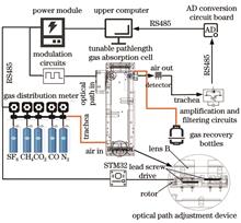
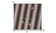
ObjectiveAt present, the infrared trace gas detection system has problems such as large size, low detection accuracy, and high minimum detection limit. As a result, certain limitations exist in the application scenarios of factories, mining areas and households which may cause serious life safety problems and huge economic losses. Most of the research on infrared trace gas detection starts from the volume fraction detection model, but it has difficult in research and little influence on the final model building results. Meanwhile, some scholars start from the cavity of the gas absorption cell to study the influence of the absorption cell on the detection of infrared trace gas, but most of the studies are based on increasing the optical path to improve the detection accuracy. However, generally the longer optical path requires larger volume of the absorption cell, which is not convenient for multi-scene utilization, and few scholars design the gas absorption cell by analyzing the optimal optical path of gas. Therefore, we employ an adjustable optical path trace gas detection system based on non-dispersive infrared (NDIR) spectroscopy with sound accuracy and low detection limits. This system can obtain the optimal detection path for different gases, and the different automatic matching paths can achieve high-precision and low-detection limit detection of gas data.MethodsAutomatic adjustment is mainly achieved for different optical paths. First, according to the concept of optical path product, the optical path for detecting the 1×10⁻⁶ volume fraction of SF6, CH4, CO, and CO2 gases is obtained by a simple pass-through gas absorption cell (Table 1). Then, based on the NDIR detection principle, the adjustable optical path gas absorption cell is designed by adopting the White cell structure. According to the structure of White cell, it is found that the relative position of the secondary lenses has a great influence on the optical path, and then the adjustment of the optical path is realized by adjusting the relative position of the secondary lenses, as shown in Fig. 4. Then, an automatic optical path adjustment device is designed (Fig. 5). The optical path automatic adjustment program is designed, with the flow chart shown in Fig. 6. Finally, the optical path under different optical paths is simulated to verify the accuracy of the automatic optical path adjustment, as shown in Fig. 7. Next, experiments are carried out based on the automatic adjustment of optical paths, the building of gas volume fraction model, the stability of detection data, and the minimum detection limit to verify the adjustment accuracy, high accuracy and low detection limit of the adjustable optical path trace gas detection system.Results and DiscussionsThe designed adjustable optical path gas absorption cell has sound accuracy and repeatability for optical path adjustment, and the relative error of automatic optical path adjustment is controlled within 1%, as shown in Table 3. The maximum RMES coefficient and the minimum R2 coefficient of the gas volume fraction model are 17.463 and 0.9964, which has sound linearity (Fig. 10). The results show that the data detected under the optimal optical path has a significant improvement, and the relative error of the gas data measured under the action of the adjustable optical path gas absorption cell and the gas volume fraction model is controlled within 8% (Table 4). Additionally, the lowest detection limit under the optimal optical path is reduced to 0.547 times compared with the lowest detection limit of a single optical path, as shown in Table 5. This indicates that the optimal optical path detection has better detection sensitivity and higher detection light intensity to adapt to more detector types than single optical path detection.ConclusionsAn adjustable optical path trace gas detection system is designed and manufactured. The system realizes automatic adjustment of the optical path of 1.6?16 m, and the relative error of the optical path is ±1%. The gas volume fraction computation model is built by adopting the least square method. The results show that the maximum detection error of SF6, CH4, CO, and CO2 gases in the experiment cannot be higher than 8% under the optimal optical path, the lowest detection limits are 1.361×10⁻⁶, 0.487×10⁻⁶, 0.420×10⁻⁶, and 0.769×10⁻⁶, respectively, and the highest detection limit is reduced to 54.7% compared with the minimum detection limit of a single optical path. The designed detection system can adapt to the gas species with the optimal optical path range of 1.6?16 m under the White cell structure, and the detection accuracy of all gases is measured at the optimal optical path. Additionally, since the optical path length of the design is not the maximum value of the optical path, the light intensity loss is relatively small, which can adapt to the light intensity requirements of various NDIR sensors and lead to sound adaptability.
Nov. 20, 2024Vol. 44 Issue 21 2104001 (2024)
Lili Zheng, Yunxia Jin, Fanyu Kong, Jianwei Mo, Yuanzhi Dong, and Jing Sun
ObjectiveWavelength division multiplexing (WDM) in optical fiber communications is widely recognized as the most effective method for increasing communication capacity due to its low cost and ease of implementation. Wavelength division multiplexing and demultiplexer devices (WDMDs) are essential components for implementing WDM technology and have remained at the forefront of optical multiplexing research. Volume Bragg gratings (VBGs) recorded in photo-thermo-refractive glass (PTRG) exhibit extremely narrow spectral bandwidths. These gratings are capable of filter different wavelengths of light by adjusting the incident angle, offering high efficiency, high transmission rates, low insertion loss, and excellent environmental stability. Therefore, they hold great potential for dense wavelength division multiplexing (DWDM) applications. However, the sidelobes caused by sudden changes in coupling strength at both ends of the grating will lead to interchannel interference, preventing the reduction of channel spacing and thereby affecting application performance. In periodic waveguide structures, a method to suppress sidelobes by varying the distribution of coupling strengths is known as apodization. Current research on apodization techniques for VBGs predominantly focuses on using a single function, such as sinc or Gaussian functions, to achieve sidelobe suppression. As far as we know, there has been no systematic comparison of the effects of different apodization functions. Therefore, this study systematically compares and analyzes the results of different types of apodization functions.MethodsWe build the apodization theoretical model of reflective volume Bragg grating (RVBG) based on F-matrix theory. The diffraction efficiency of different apodized volume Bragg gratings is normalized by defining effective refractive index modulation. The apodization effects of cosine, Gaussian, and secant functions are systematically compared and analyzed. An RVBG filter for the C-band is designed based on the established model, providing a theoretical design basis for the development of high signal-to-noise ratio RVBG filters.Results and DiscussionsThe performance of three refractive index modulation distribution functions, namely cosine, Gaussian, and hyperbolic secant, is examined in RVBGs with a center wavelength of 1550 nm and a thickness of 5 mm. The simulations are conducted to evaluate the efficacy of sidelobe suppression in both the spectral and angular domains. The cosine function exhibits exceptional utilization efficiency in PRRG, with the best diffraction efficiency without additional peaks at the edges of the spectrum for samples of the same thickness and exposure. Gaussian and hyperbolic secant functions demonstrate deeper out-of-band suppression capabilities through parameter adjustments unattainable by the cosine function. However, the hyperbolic secant function exhibits subpar sidelobe suppression, leading to decreased efficiency in utilizing the same glass substrate. The diffraction efficiency of the main lobe in RVBGs is determined by the effective refractive index modulation (ERIM). When the ERIM remains constant, increasing thickness (or refractive index modulation) affects the bandwidth without changing the diffraction efficiency magnitude or spectral shape. Conversely, keeping the thickness constant but changing the maximum refractive index modulation affects both the diffraction efficiency and the spectral features. By adjusting the refractive index modulation and thickness according to requirements, controlling the magnitude of ERIM, and ensuring that the center of the apodization function deviates minimally from the center of the sample, RVBGs with the required performance can be designed and prepared. In addition, Gaussian and hyperbolic secant apodized gratings generate additional peaks at the first zero point, which change periodically with the increase of ERIM. When ERIM is appropriate, these additional peaks disappear.ConclusionsBased on F-matrix theory, a theoretical model to analyze the apodized RVBG of various function types is established. By defining the ERIM, normalization of the refractive index modulation for the apodization function is achieved, facilitating easier comparison of results from various apodization functions. We further analyze the apodization influences of cosine, Gaussian, and hyperbolic secant functions. Simulation results demonstrate that apodized gratings significantly suppress sidelobes. With constant diffraction efficiency, all three functions reduce the first and second sidelobes to below 1.1% and 0.3%, respectively. The study concludes that the main lobe diffraction efficiency and the shape of the diffraction efficiency spectrum are determined by the ERIM. When the ERIM is fixed, the diffraction efficiency remains consistent, while the spectral bandwidth expands as the grating thickness increases. With a constant thickness, both the diffraction efficiency and bandwidth increase with the maximum refractive index modulation. The capability to reduce the intensity of the first-order sidelobes decreases gradually from cosine to Gaussian to hyperbolic secant functions. An RVBG filter is designed to have a high signal-to-noise ratio based on theoretical research. Utilizing a Gaussian function (m=3) as the apodization function, it achieves an efficiency exceeding 90% and a spectral bandwidth of less than 0.8 nm. This design allows for the continuous wavelength selection for C-band filters by adjusting the angle, resulting in a sideband suppression of around 50 dB.
Nov. 10, 2024Vol. 44 Issue 21 2105001 (2024)
Yunpu Gao, Yang Liu, Yunjie Teng, Jianhua Liu, Sisi Zhao, and Weidong Shang
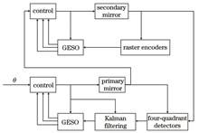
ObjectiveCompared to the mainstream microwave communication methods, laser communication offers advantages such as high data rate, large capacity, compact size, low power consumption, and strong confidentiality. As satellite laser communication becomes increasingly practical, laser communication networking has emerged as a crucial research direction and foundational technology for future space-based communication. However, the narrow beam divergence of laser limits them to point-to-point communication, making them unsuitable for the wide coverage typically achieved with radio frequency communication. Achieving multi-beam, high-precision control under complex space conditions is one of the key challenges in inter-satellite laser communication networking. Currently, most laser communication tracking servo systems utilize the proportional-integral-derivative (PID) control algorithm. While there have been improvements to traditional control algorithms and applications of modern control methods, issues such as low control accuracy and application difficulty remain. In this study, we propose an improved active disturbance rejection control (ADRC) algorithm designed to improve control accuracy in laser communication networking.MethodsThe control strategy for a one-to-many laser communication terminal is studied. The structure and control system of a one-to-many coarse tracking optical antenna are analyzed. Based on ARDC principles, a model-assisted extended state observer combined with a Kalman filter is developed to improve disturbance estimation. The controller is designed using the desired frequency response method. Simulations are conducted, followed by experiments on an indoor platform.Results and DiscussionsIn linear ADRC, the system is treated as a simple integrator chain when designing the control law. By incorporating known model information into the design of the extended state observer, we overcome the performance limitations of traditional observers. Thermal noise and ambient light can affect the positioning accuracy of the four-quadrant detector. While code division multiple access (CDMA) techniques can reduce background light interference, they cannot fully eliminate it. Therefore, a Kalman filter is introduced before the extended state observer to reduce overall measurement error, with its output serving as input for the observer. The controller is designed using the desired frequency correction method, which is known for stable performance and ease of implementation. Modeling errors and external disturbances are compensated for by the improved extended state observer, bringing the actual system model closer to the ideal model. Simulation results indicate that the Kalman filter effectively suppresses high-frequency noise. Under traditional PID control, the peak tracking residual is 1.71°, with a root mean square (RMS) of 0.95°. For linear ADRC control, the peak is 1.21° and the RMS is 0.75°. With the improved linear ADRC, the peak tracking residual is reduced to 0.92°, with an RMS of 0.38°, significantly outperforming both PID and linear ADRC controls. In the experiments, the error peak for the primary mirror under PID control is 171.2 μrad, with an RMS of 69.66 μrad. With the improved ADRC, the error peak is reduced to 134.1 μrad, with an RMS of 45.50 μrad. For the slave mirror linkage control, the error peak under PID control is 33.81 μrad, with an RMS of 11.49 μrad, while the improved ADRC reduces these values to 20.22 and 6.81 μrad, respectively. These results show that the control accuracy for the primary mirror improved by 34.6% compared to PID control, and for the slave mirror, by 40%. The consistency between the simulation and experimental results verifies the effectiveness of the proposed control algorithm.ConclusionsTo enhance disturbance estimation, known model information is incorporated into the extended state observer. To mitigate the effect of noise from the four-quadrant detector, a Kalman filter is applied before the observer’s input. In addition, loop bandwidth compensations are integrated into the controller design. Experimental results demonstrate that the tracking accuracy for the dual spot is better than 50 μrad, with a 34% improvement over traditional algorithms. This confirms the feasibility of applying the improved ADRC to multi-beacon tracking scenarios, highlighting its advantages over traditional control methods and its potential to support laser communication applications in inter-satellite networking.
Nov. 19, 2024Vol. 44 Issue 21 2106001 (2024)
Yi Huang, Zongling Zhao, Bingtao Cai, Chengyong Hu, Chuanlu Deng, Qi Zhang, Wei Chen, Xiaobei Zhang, and Tingyun Wang
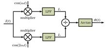
ObjectiveInterferometric fiber optic sensors are widely used in underwater target detection, oil and natural gas prospecting, and earthquake monitoring due to their high sensitivity, large dynamic range, immunity to electromagnetic interference, and ease of large-scale array implementation. The phase-generated carrier (PGC) demodulation technique is a crucial signal processing scheme for these systems, offering a simple optical structure, large dynamic range, high resolution, and good linearity. However, traditional PGC arctangent (Arctan) and PGC differential cross multiplication (DCM) algorithms are affected by light intensity disturbance (LID) phase modulation depth (C value) drift and carrier phase delay (θ), leading to nonlinear distortions in the demodulation results. Additionally, if the θ is a singularity (kπ/4), the phase signal may not be recovered.MethodsTo simultaneously eliminate the effects of these factors, we propose an improved scheme with high stability and low harmonic distortion, which combines a multi-harmonic mixing technique, a nonlinear curve fitting algorithm, and a sign recovery method. First, we mix the in-phase and quadrature components of three pairs of reference carriers with the interference signal, followed by low-pass filtering to eliminate high-frequency carrier components. The signals without the carrier phase delay term are obtained by squaring and summing the filtered signals. The Levenberg-Marquardt (LM) nonlinear curve fitting algorithm is then applied to derive an error compensation equation that relates J3(C)/J1(C) to J2(C)/J1(C). This allows us to obtain J2(C)/J1(C) in real time, compensating for nonlinear errors caused by C value drift. As the multi-harmonic mixing involves square root operation, we use the sign of the filtered signal to recover the demodulated signal. For phase singularities (kπ/4), the filtered signal becomes noise, requiring an efficient sign recovery method. Our method identifies phase singularities, determines the phase delay range, and selects the appropriate sign recovery function to prevent phase signal inversion.Results and DiscussionsSimulations in MATLAB demonstrate that our algorithm performs stably across C values from 1.5 rad to 3.0 rad and phase delays from 0 to π (Fig. 8). At phase delays of π/4 or π/2, traditional algorithms like PGC-Arctan, PGC-SDD-DSM, and PGC-DSVV algorithms fail (Fig. 9). Additionally, PGC-Arctan and PGC-DSVV algorithms exhibit phase inversion at a delay of 3π/8, while our improved algorithm remains unaffected by simultaneous variations in C value and phase delay, performing well even at singularities. We then construct a PGC demodulation system using a Michelson interferometer with unequal arms and conduct comparison experiments to validate our approach. The C value fluctuated around 2.63 rad due to the unstable power of the electro-optical modulator (EOM), while the initial phase delay resulted from the transmission and conversion time delay of the optical signal. Additionally, the initial phase delay between the interference signal and the reference carrier depends on the transmission and conversion time delay of the optical signal. With the combined effect of C value drift and phase delay, the demodulated waveforms of the PGC-Arctan and the other algorithms become distorted. In contrast, the improved algorithm remains insensitive to nonlinear factors, achieving a signal-to-noise and distortion ratio (SINAD) of 54.52 dB and a total harmonic distortion (THD) of 63.04 dB (Fig. 11). Compared to the PGC-Arctan scheme, the SINAD of the proposed algorithm increases by 6.38 dB, while the THD decreases by 14.30 dB (Table 2). The demodulated waveform of the improved algorithm shows no inversion across the phase delay range from 0 to π, with stable performance at phase singularities (Fig. 12). To test the linearity of the improved algorithm, the amplitude of the phase signal is gradually increased from 100 mV to 1000 mV, and the correlation coefficient between the input and output linearity of the demodulation system exceeds 99.99% (Fig. 13).ConclusionsWe propose an improved PGC demodulation algorithm combining the multi-harmonic mixing technique and the LM nonlinear curve fitting method. This algorithm effectively eliminates the influence of modulation depth drift and carrier phase delay on the demodulated signal. Simulation and experimental results align with theoretical predictions, confirming the algorithm's advantages in stability, low harmonic distortion, low computational complexity, and hardware implementation. The proposed method holds great promise for signal processing in interferometric fiber optic sensors.
Nov. 19, 2024Vol. 44 Issue 21 2106002 (2024)
Lixin Zhang, Qinghua Kang, Da Huang, Kai Huo, Zijuan Liu, and Yongqian Li
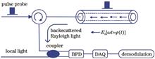
ObjectiveDistributed acoustic sensing systems based on phase-sensitive optical time-domain reflectometer (Ф-OTDR) are commonly used for vibration signal detection. When external vibrations are applied to the sensing optical fiber, the fiber’s refractive index changes, leading to variations in the phase of the backscattered Rayleigh light at the vibration location. Since the phase change of the backscattered Rayleigh light is linearly related to the vibration applied to the fiber, external vibration signals can be measured based on these phase changes. However, phase ambiguity often occurs during demodulation, resulting in distorted phase values, making it difficult to accurately reflect the vibration information. Common demodulation methods, such as the arctangent method, can extract the phase, but due to the phase’s periodicity and variability, only the wrapped phase with a period of 2π and a principal value interval from -π to π can be obtained. As the vibration measurement range increases, if the phase change exceeds 2π, phase ambiguity occurs, leading to demodulated phase results that cannot accurately reflect the vibration amplitude and frequency.MethodsTo address the phase ambiguity issue, we propose a phase demodulation algorithm based on differential-compensation-accumulation, building on digital in-phase and quadrature (IQ) demodulation. This algorithm provides a reliable phase compensation scheme to solve phase ambiguity, making the differential phase no longer dependent on the jump threshold of π. It effectively avoids phase misalignment caused by phase changes exceeding 2π, enabling accurate extraction of phase information from vibration signals. The Ф-OTDR digital IQ demodulation process is divided into three processes: mixing, filtering, and phase demodulation. Since the phase information obtained by digital IQ demodulation is mainly distributed between -π/2 and π/2, arctangent unwrapping in a four-quadrant manner is required. A backward differential operation is then applied to the arctangent phase signal to eliminate accumulated phase noise and prevent its global propagation, minimizing errors. By selecting appropriate compensation coefficients in the differential domain to adjust the phase signal, the difference between adjacent elements is reduced to less than π. The optimal compensated phase solution is then accumulated, yielding accurate phase values and effectively reducing errors caused by discontinuities.Results and DiscussionsIn the Ф-OTDR experimental system, vibration signals with frequencies of 20, 60, and 100 Hz are detected. When comparing the time-phase plots of the 60 Hz sinusoidal signal obtained using the proposed algorithm and the traditional unwrapping algorithm [Figs. 8(a) and 8(c)], it is clear that the proposed algorithm is less influenced by phase noise and frequency drift, with good continuity and high accuracy in the demodulation results. However, the results obtained by the unwrapping algorithm show errors when phase changes exceed the adjacent point’s phase change limit [Fig. 8(c)]. A comparison of the phase power spectral density (PSD) of the 60 Hz vibration signal shows that the proposed algorithm experiences less noise interference, with a signal-to-noise ratio (SNR) of 24.7 dB. The PSD obtained by the unwrapping algorithm is more disturbed by noise, particularly in the <60 Hz frequency range, with an SNR of 17.4 dB. Therefore, the proposed demodulation algorithm improves the SNR by 7.3 dB compared to the unwrapping algorithm [Figs. 9(a) and 9(b)]. Similarly, the 20 and 100 Hz sinusoidal signals are well constructed using the proposed demodulation algorithm [Figs. 11(a) and 11(b)]. The PSD analysis of the 20 Hz and 100 Hz signals reveals that the signal power is concentrated around their respective frequencies, with SNRs of 27.4 and 32.4 dB, respectively [Figs. 11(c) and 11(d)], demonstrating the accurate recovery of external vibration signals.ConclusionsPhase ambiguity is a common limitation in many phase demodulation methods, restricting the vibration measurement range. We propose a differential-compensation-accumulation demodulation algorithm for recovering vibration signals in Ф-OTDR distributed fiber sensing systems, accurately reconstructing sinusoidal signals loaded on the optical fiber. Unlike traditional demodulation algorithms, the proposed algorithm produces continuous demodulated phases over time, avoiding phase errors caused by changes exceeding 2π. Compared to unwrapping algorithms, the proposed algorithm significantly improves phase demodulation accuracy and reduces phase noise interference, enhancing the system’s SNR.
Nov. 18, 2024Vol. 44 Issue 21 2106003 (2024)
Renlong Zhang, Dexu Kong, Jiawei Zhang, Yufei Zhang, and Qiang Liu
ObjectiveGas pressure sensors are essential components in many measurement systems. They hold great value in industrial, medical, environmental monitoring, aerospace, and geological exploration applications, which provide accurate and reliable means of monitoring and controlling gas pressure across various industries. Fiber optical sensors, with their small size, high sensitivity, resistance to electromagnetic interference, and fast response speed, offer marked advantages in measuring physical parameters such as temperature, pressure, and refractive index in sensing applications. The Fabry?Pérot interferometer (FPI), commonly used for gas pressure detection due to its simple fabrication process, has been extensively researched. Previous studies often employed hollow-core fibers (HCFs) as the sensing cavities, leveraging the principle that the gas’s refractive index changes with increasing air pressure. However, a challenge arises in ensuring smooth air entry into the air holes of HCFs. Photonic crystal fibers (PCFs) feature a porous structure that allows gas to smoothly enter the HCF without collapsing or fusing the air holes, even under increased air pressure induced by a pump. This enables the gas inside the PCF to change its refractive index, facilitating accurate gas pressure sensing.MethodsFirstly, the fabrication process of the sensing probe involves only two steps: fusion splicing and cutting, which are accomplished using a fiber optical cutter and a fiber optical fusion splicer. Since there is no specific fusion splicing procedure in the fusion splicing machine, it is necessary to pre-set the fusion splicing parameters for the single-mode fiber and the HCF, as well as the fusion splicing parameters for the HCF and the PCF. This ensures that the HCF does not collapse and minimizes the collapse of the air holes in the PCF, which could otherwise affect the experimental results. Secondly, the length of the PCF has a negligible effect on spectral loss. In this study, the lengths of the HCF and PCF sensing probes are approximately 60 and 370 μm, respectively, which results in a total probe length of about 430 μm. As the ambient gas pressure fluctuates around the sensing probe, the refractive index of the gas within the HCF responds correspondingly to these variations. This change is observable in the reflectance spectra, allowing the sensing probe to detect variations in gas pressure. Lastly, in a similar structure, the single-mode photonic crystal fiber (SM-PCF) is replaced with a large-mode-field photonic crystal fiber (LMA-PCF), and the obtained reflection spectra effectively reflect changes in gas pressure. The sensitivities of the sensing probes using the two different PCFs are compared.Results and DiscussionsWith increasing air pressure, the reflectance spectrum of the sensing probe exhibits a redshift trend. The trough induced by air pressure shifts up to about 3.84 nm/MPa, demonstrating a high linearity of 0.99832 [Fig. 9(a)], which confirms the stability of the gas pressure sensing probe. The sensitivity of the probe aligns consistently with the theoretically calculated gas pressure sensitivity. Theoretically, the probe can detect a maximum gas pressure of 4.76 MPa. However, due to equipment limitations, this study achieves a maximum measured gas pressure of 2.5 MPa. The sensitivity remains nearly unchanged within the 0?2.5 MPa range, highlighting the excellent stability of the sensing probes during gas pressure measurements, as depicted in Figs. 10(a) and 10(b). Table 1 outlines the parameter settings for the fusion splicer used in preparing the sensing probe. Precise control of these parameters is essential to prevent the collapse of air holes in both the HCF and PCF.ConclusionsIn this paper, a highly sensitive all-fiber air pressure sensor with a pressure sensitivity of about 3.84 nm/MPa has been implemented. The sensing probe is fabricated by cascading single-mode fiber, HCF, and PCF. The preparation process is simple and requires only two steps: splicing and cutting. In this study, the HCF serves as the sensing cavity and the PCF as the gas channel. Light beams are reflected from the end face of the single-mode fiber and the two ends of the PCF, which create three types of reflected beams whose interference superposition forms the total output spectrum. The interference spectrum of the cavity formed by the HCF is obtained through fast Fourier transform and Fourier band-pass filtering, which is much simpler than analyzing the entire output spectrum and facilitates subsequent demodulation. Several sensing probes are fabricated by varying splicing parameters, HCF, and PCF lengths. It is observed that their sensitivities vary minimally, demonstrating strong repeatability in probe fabrication. The temperature sensitivity of the fiber optical sensing probe is 12.1 pm/℃. This all-fiber air pressure sensor offers advantages such as high sensitivity, good linearity, compact size, easy preparation, simple operation, and remote monitoring, which indicate broad potential applications across various fields.
Nov. 10, 2024Vol. 44 Issue 21 2106004 (2024)
Gui Ru, Ling Qin, Fengying Wang, Xiaoli Hu, and Desheng Zhao
ObjectiveCoal is an important energy resource in China and has long been the primary source of energy consumption. However, most coal resources are buried underground, posing significant safety challenges for underground coal mining. Moreover, the high incidence of coal mine accidents has adversely affected the development of the coal economy. To effectively enhance rescue outcomes in coal mine accidents, it is crucial to quickly and accurately locate trapped individuals and devise efficient rescue strategies. Big data analysis underscores these priorities as pivotal for significantly improving rescue operations. However, the underground environment of coal mines is complex and variable, which makes it difficult for traditional positioning systems to attain high accuracy. Therefore, achieving high-precision positioning of underground personnel has become an urgent problem to be solved. Based on this, we are dedicated to researching a new photodiode (PD) array receiver and installing it on miners’ helmets to achieve high-precision positioning of underground workers in this study.MethodsFirstly, we delve into how differently shaped PD array sensors affect the performance of the visible light positioning system in underground coal mines. The arrays are classified into a square 2×2 array, square 3×3 array, circular PD array (both square and ellipsoid), and umbrella PD array (both square and ellipsoid) based on their arrangement. Next, the neural network parameters are discussed to determine the optimal settings for positioning. Simulations of PD array sensors with the aforementioned arrangements are conducted to compare their positioning performance. Finally, a PD array receiver with optimal performance is selected to implement the visible light positioning system for underground coal mine operations.Results and DiscussionsWe first discuss the network parameters of the SRU neural network to determine the optimal settings. The initial step involves simulating the square-type PD array receiver, where it is observed that the 3×3 square-type PD array receiver outperforms the 2×2 counterpart (Table 6). It is established that increasing the number of PDs improves the system’s ability to receive comprehensive information about the light source, thereby reducing positioning errors. Consequently, an array configuration of nine PDs is selected. Next, the positioning performance of the circular PD array receiver and the umbrella PD array receiver are separately considered and simulated to obtain their respective results (Tables 7 and 8). By comparing these simulation outcomes, it is determined that the elliptical umbrella PD array receiver exhibits optimal positioning performance under similar environmental configurations. Finally, the positioning algorithm based on the SRU neural network is compared with that based on the sparrow search algorithm optimized deep confidence network. It is found that the SRU neural network-based algorithm demonstrates superior positioning performance, which confirms the efficacy of the proposed algorithm in this study.ConclusionsOur study focuses on designing and optimizing a visible light positioning system using PD array sensors for underground coal mines. Initially, the PD array sensor is selected as the primary light sensing component, and its structural characteristics and working principles are thoroughly studied to ensure high sensitivity and accuracy. Various PD array configurations (square, circular, and umbrella PD arrays) are introduced and analyzed in terms of their characteristics and suitable applications. Further discussed are network parameters of the neural network, followed by the construction of a comprehensive visible light positioning system tailored for underground coal mines. This system utilizes advanced SRU neural network technology and principles of visible light positioning to achieve precise localization of targets. Several sets of simulation experiments confirm an average positioning error of 0.94 cm within a 3.6 m×3.6 m×3 m space, with a training time of 1 s, meeting the requirements for underground positioning in coal mines.
Nov. 20, 2024Vol. 44 Issue 21 2106005 (2024)
Zhanqi Liu, Huatao Zhu, Zhengyi Tang, Yongliang Yin, Yibo Liu, Xianyu Zhang, and Chen Wang
ObjectiveWith the rapid development of technologies such as 6G, virtual reality, and artificial intelligence, information transmission and interaction are becoming increasingly frequent, leading to a growing amount of data transmitted through optical fiber networks every year. However, optical fiber transmission systems are vulnerable to illegal eavesdropping, making it crucial to ensure the security of data transmission in optical fiber networks. Quantum noise stream cipher (QNSC) is a new optical network security transmission technology that combines traditional encryption technology with physical layer security technology. Ensuring security requires both the transmitter and the receiver to share a secure key. However, in actual QNSC systems, ensuring the true randomness of the key is challenging, and the exposure of communication behavior may attract the attention of eavesdroppers, greatly increasing the risk of the key being broken by brute force. The imperceptibility of the transmitted signal can be enhanced by hiding the QNSC signal within noise. To further improve the security performance of QNSC communication systems, we propose a quantum noise stream cipher optical covert communication scheme based on differential phase shift keying (DPSK). The QNSC signal is covertly transmitted in a public channel for transmission. By increasing the key bases, the power of the mesoscopic coherent state can be increased, enhancing the transmission performance of the covert channel. The expression of quantum noise masking state bases for the DPSK balanced detection receiver is derived, and the tradeoff between concealment and transmission is discussed. Simulation results confirm the feasibility of covert communication, showing compatibility with wavelength-division multiplexing (WDM) systems. At a transmission distance of 250 km, the covert channel achieves error-free communication.MethodsThe structure of the DPSK-QNSC optical covert communication system is shown in Fig. 1. Covert communication is realized by injecting the signal into the WDM network. The data to be transmitted is differentially coded at the transmitter and then encrypted with a key. The legitimate transmitter, Alice, and the receiver, Bob, share the same seed key. A Gaussian pulsed laser source is used as the optical carrier signal and is broadened in the time domain due to dispersion. The encrypted ciphertext is loaded onto the optical carrier by a phase modulator and transmitted. A variable optical power attenuator (VOA) attenuates the optical signal to the mesoscopic coherent state. This signal is then injected into the public channel of the WDM system for transmission. The legitimate receiver uses an optical filter to extract the signal from the public channel, and the covert signal is recovered by matching the dispersion and decryption keys.Results and DiscussionsSimulation results demonstrate that the proposed DPSK-QNSC optical covert communication scheme can be integrated into a public WDM system. When the dispersion in the covert channel is low, it cannot be hidden in the time domain [Fig. 5(a)]. However, increasing the dispersion allows the covert channel to be completely hidden in the time domain [Fig. 5(b)]. The covert channel can be completely hidden in the frequency domain, preventing eavesdroppers from detecting its existence by observing the spectrum (Fig. 6). As the key bases increase, the power of the mesoscopic coherent state of the covert signal increases, reducing the bit error rate for the receiver and improving system performance. The covert channel has negligible impact on the public channel because it is located in the frequency band between two WDM channels.ConclusionsTo address the issue of communication exposure in QNSC systems, we propose an optical covert communication system based on DPSK-QNSC, offering dual security protection of concealment and confidentiality, thus enhancing the overall system security. The effect of key bases on the performance of the DPSK-QNSC optical covert communication system is explored. Simulation results show that the QNSC signal can be hidden in both frequency and time domains. Increasing the key bases improves the transmission performance of the system but at the cost of decreasing the hiding performance. Although increasing the key bases can raise the upper limit of the power of the mesoscopic coherent state for the covert signal and thus improve the transmission performance, the improvement is not linear. Key bases cannot be increased indefinitely, and hiding the covert channel requires that the transmit power remains below a certain value. Within this range, the optimal balance between hiding performance and transmission performance for the DPSK-QNSC optical covert communication system can be achieved.
Nov. 20, 2024Vol. 44 Issue 21 2106006 (2024)
Min Sun, and Nian Fang
ObjectiveThe distributed optical fiber sensing system based on a phase-sensitive optical time-domain reflectometer (φ-OTDR) has been widely used for disturbance signal recognition in perimeter security, pipeline monitoring, railway transportation monitoring, and other fields, due to its advantages of high sensitivity, multi-point monitoring, and wide coverage. Currently, machine learning-based methods are the primary approach to enhance the accuracy of disturbance signal recognition. Classical machine learning algorithms require preprocessing of raw input signals through manual feature extraction. Typically, increasing the number of extracted features is aimed at achieving higher recognition accuracy with the growth in the number of disturbance events. However, introducing irrelevant features can adversely affect recognition accuracy and efficiency. Therefore, the feature selection process, which eliminates irrelevant features to strengthen recognition performance, plays a crucial role in the preprocessing stage. Feature selection methods can be categorized into three types: filter, wrapper, and embedded methods. Particularly, most feature selection methods used for optical fiber disturbance signal recognition fall under the filter method category, often overlooking the relationship between features and models. In this study, we aim to develop a more efficient and interpretable feature selection method for identifying key features to further boost recognition performance.MethodsWe propose a novel feature selection method based on Shapley additive explanations (SHAP), which is an explainable artificial intelligence (XAI) method. SHAP is inspired by game theory to calculate the Shapley value, which can quantify the contribution of each feature to the model’s prediction (Equation 1). We use SHAP to obtain the mean SHAP value for a classification model. The higher the mean, the more important the feature. We rank the features by importance and select some of the most significant ones to form a feature subset while ensuring high recognition rates. This subset is used to retrain the model, thereby improving recognition efficiency.Results and DiscussionsExperimental validation is conducted using an open dataset of optical-fiber disturbance events from Beijing Jiaotong University, divided into training and test sets at an 8∶2 ratio (Table 1). The dataset includes six typical disturbance events: background noise, digging, knocking, watering, shaking, and walking. We extract sixteen time-domain features from the disturbance signals after differentiation and segmentation. Additionally, wavelet packet decomposition (WPD) is employed to extract six frequency-domain features (Tables 2 and 3). The feature set, comprising twenty-two features, is normalized and inputted into four common machine learning models as baselines: support vector machine (SVM), K-nearest neighbor (KNN), decision tree (DT), and random forest (RF). KernelSHAP is applied to SVM and KNN, while tree SHAP is used for DT and RF. The ranking of these twenty-two features is determined across the four models (Fig. 6). Importantly, each feature contributes differently to the classification of the six disturbance events depending on the model. To maintain recognition accuracy without compromise, we retain a varying number of key features for each model. Comparing the accuracy, precision, recall, and F1-score from the test confusion matrices (Tables 4?5), we observe improvements in recognition performance across varying degrees due to feature selection. Among the four models, the RF model achieves the highest recognition accuracy of 96.5%. Furthermore, the average recognition time per sample for the RF model decreases from 81.82 ms without feature selection to 66.01 ms, which marks a 19.3% reduction (Table 6). Common feature selection methods such as fisher score and mutual information are also used for comparison with the SHAP-based feature selection method. The SHAP-based method demonstrates superior recognition accuracy compared to these alternatives (Table 7).ConclusionsWe propose a feature selection method characterized by interpretability and reliability. This method leverages explainable AI (XAI) techniques to quantify the importance of different features for the model and selects them based on their importance rankings. By retaining the most effective features for model classification and discarding redundant or detrimental ones, our approach enhances recognition accuracy while reducing computational costs and identification time. Twenty-two features are extracted from six types of disturbance events using an open dataset from Beijing Jiaotong University. We employ four common machine learning models for signal recognition. By carefully considering variations in feature importance rankings across models, we construct different subsets of features. This results in significant decreases in single-sample testing times for all four models and varying degrees of improvement in average recognition accuracy. Compared with filtering methods based on statistical metrics, our proposed method selects more valuable features, thereby achieving higher recognition rates. It is important to note that these conclusions are drawn solely from the dataset used. Further validation is necessary to assess its applicability to more complex or real-world datasets. Future work could involve comparing feature importance rankings across more models and integrating other feature selection methods to develop a versatile approach for optical-fiber disturbance signal recognition.
Nov. 10, 2024Vol. 44 Issue 21 2106007 (2024)
Cheng Tian, Jing Li, Weichen Zhao, Li Pei, and Tigang Ning
ObjectiveMicrowave instantaneous frequency measurement (IFM) is part of electronic measurement technology. The measured signal is a series of periodic and narrow duration microwave pulses, and the carrier frequency of a single pulse may change rapidly. In this case, the measured signal cannot be measured multiple times. Rapid frequency measurement in a short period of pulse duration enables the acquisition of frequency-related information when the RF signal is intercepted. IFM technology has applications in electronic countermeasures, radar early warning, and modern communications. However, traditional electronic IFM systems are restricted by limited bandwidth, vulnerability to electromagnetic interference (EMI), and high power consumption. In recent years, photonic-assisted frequency measurement systems have been proposed and proved because of their large bandwidth, low loss, light weight, and anti-electromagnetic interference. At present, the common implementation methods of microwave photon IFM systems are roughly divided into frequent-to-time mapping (FTTM), frequent-to-space mapping (FTSM), and frequent-to-power mapping (FTPM). As one of the most commonly employed methods in IFM, FTPM maps the RF to be measured into the power ratio between two optical/electrical power channels and constructs the amplitude comparison function (ACF) to identify the RF frequency instantaneously. The FTPM method usually adopts dispersive media, optical filters, or polarization control to achieve optical/electrical power mapping. The dispersion class scheme utilizes the power fading caused by fiber dispersion to construct electrical power ACF, which is limited by the medium material and usually does not have the continuous tunability of measuring range and accuracy. Optical filtering schemes leverage spectral complementarity to construct optical power ACF. However, filters with specific spectral responses are greatly affected by the wavelength drift of the light source, thus affecting the measurement error. The polarization control scheme employs polarization interference characteristics to construct wavelength-independent optical power ACF, which can avoid the utilization of optical filters and thus reduce the measurement error caused by the wavelength drift of the light source. However, the polarization state is unstable and greatly affected by environmental factors.MethodsWe propose a transient frequency measurement scheme for AC/DC power detection based on a double-parallel Mach-Zehnder modulator (DP-MZM). The proposed scheme is modulated by DP-MZM, introduces an adjustable time delay, maps the RF frequency information to the phase of the optical field, and constructs an electrical power ACF based on the AC and DC power values of photocurrent after photoelectric detection. The DC and AC power values will be determined by detecting the photodetector output and the divider output respectively to employ a single detection branch for frequency to power mapping. Finally, the corresponding instantaneous frequency is obtained by the inverse solution of the constructed ACF. The scheme design will help to reduce the utilization of high-frequency devices and decrease the implementation cost and complexity.Results and DiscussionsThe system employs DP-MZM to modulate the signal while utilizing only one photodetector (Fig. 1). The system has an important characteristic of wavelength independence, and the maximum frequency range is determined by the time delay. A larger frequency measurement range can be obtained by reducing the time delay (Fig. 4). Simulation results show that the error tolerance is 200 MHz in the whole frequency range. Meanwhile, the system deterioration is analyzed with higher harmonics considered (Fig. 9). We also analyze the factors affecting the frequency range and accuracy of the system, such as modulation coefficient, bias voltage drift, and extinction ratio. The respective error tolerances are obtained.ConclusionsWe propose a transient frequency measurement scheme for AC/DC power detection based on DP-MZM modulation. The RF frequency information is mapped to the optical field phase by an adjustable delay, and after being converted to the electrical domain by PIN, the electric power ACF is constructed by employing the AC and DC power values of the current. The DC and AC power values are determined by detecting the PIN output and the output of the divider respectively. Meanwhile, only a single detection branch is needed to realize frequency power mapping. While verifying the feasibility of the theory, we discuss the error sources that affect the measurement frequency accuracy of the system, such as modulation coefficient, MZM bias voltage drift, and extinction ratio. Finally, it is found that if sufficient accuracy needs to be guaranteed, which means the error range is within ±200 MHz and sufficient frequency measurement range is required, the system tolerance should meet the small signal modulation. This indicates that the modulation coefficient m<0.5, the bias voltage drift degree ΔVbias12<2.0%, ΔVbias3<2.0%, and the system tolerance should meet the small signal modulation. The extinction ratio should meet Er>30 dB.
Nov. 19, 2024Vol. 44 Issue 21 2107001 (2024)
Lihua Xu, Yibo Zhao, and Chengdong Yang
ObjectiveInspired by the biological nervous system, the neuromorphic hardware implementation based on compute-in-memory (CIM) architecture and highly adaptive computing mode are promising to significantly improve computer efficiency and performance. At present, it is still a great challenge to integrate system-level neuromorphic hardwares, and neuromorphic computing with high recognition accuracy can be realized by adopting synaptic devices in combination with neural network algorithms. Therefore, an optical synaptic device based on back-to-back Schottky junction (B-B SJ) is presented, and then some common synaptic plasticities are emulated, such as post-excitatory synaptic currents (EPSCs), short-to-long-term plasticity, interval-dependent paired-pulse facilitation (PPF), and learning-forgetting-relearning process. Additionally, the memristor-based convolutional neural network (M-CNN) is constructed by mapping the device conductance change to the weight change of the convolutional neural network, and its applications in image recognition are evaluated. Meanwhile, the experimental results show that the recognition accuracy can reach 95.12% and demonstrate the potential applications of devices in neuromorphic computing.MethodsOptical synaptic devices have been proposed based on B-B SJ. The device conductance is modulated by light-induced Schottky barrier modulation, with simultaneous non-volatile conductance state regulation achieved via the silicon dioxide interface trapping effect. Synaptic behavior such as EPSC, PPF, short-to-longterm plasticity, and PPF has been successfully emulated by adopting B-B SJ devices. Furthermore, by extracting the device conductance and mapping the conductance range into the M-CNN algorithm, image information recognition has been accomplished. The results indicate that by adopting the M-CNN algorithm, this neuromorphic device demonstrates outstanding performance in image recognition tasks, with an accuracy of up to 95.12%.Results and DiscussionsAn M-CNN is constructed to test its image recognition performance. The conductance values of the devices are mapped as weight values for image recognition. Figure 4(a) presents a schematic diagram of this process, while Fig. 4(b) shows the feature maps of the convolutional layer. Different numbers of pulses are applied to the device, which results in three distinct conductance ranges as illustrated in Fig. 4(c). The corresponding changes in conductance values for these three scenarios are depicted in Fig. 4(d), indicating that an increase in the pulse number enhances the conductance range of the device. The confusion matrices and accuracy distribution plots for the M-CNN recognition rates corresponding to different pulse numbers are shown in Fig. 5. A comparison with the results in Table 1 reveals that the image recognition network constructed by the B-B SJ artificial synapse device performs well in image recognition tasks, demonstrating high accuracy and further validating the effectiveness of the device for neuromorphic computing.ConclusionsA B-B SJ artificial synapse device is fabricated to simulate various plasticity behaviors of biological synapses, including EPSC, short-to-long-term plasticity, interval-dependent PPF, and learning-forgetting-relearning process. Additionally, the corresponding conductance parameters are extracted from this artificial synapse device, and a three-layer CNN based on this device is constructed. This network achieves a recognition accuracy of 95.12% in tests on the MNIST handwritten digit dataset. These results demonstrate the device’s advantages in image information processing and confirm its potential as an artificial synapse device for neuromorphic computing applications.
Nov. 20, 2024Vol. 44 Issue 21 2110001 (2024)
Dawei Gan, Zhiqiang Liu, Wenbin Feng, and Mao Ye
ObjectiveDue to the optical anisotropy of liquid crystal materials, a polarizer is typically required in front of the liquid crystal lens when used in imaging systems. However, the polarizer reduces the intensity of incident light and increases the size of the imaging system. This has made polarization-free imaging a key research area for liquid crystal lenses. Currently, there are three main methods for achieving polarization-free imaging. The first method utilizes the Kerr effect in blue-phase liquid crystals to control the refractive index in different regions. This method eliminates the need for alignment layers, significantly simplifying the lens manufacturing process. However, blue-phase liquid crystals require high driving voltages and have a narrow temperature range, limiting their practical applications. The second method is the “full lens” approach, which stacks two liquid crystal lenses with orthogonal optical axes. Although this combination can modulate natural light, it increases the thickness and cost of the device. The third method employs a polarization-free imaging algorithm (PFI). Previous approaches have achieved polarization-free imaging by subtracting the image in the lens’s non-working state from the image in the working state, thus removing the unmodulated polarized light. However, this method requires capturing two images, resulting in relatively long processing times. Therefore, a faster, device-independent method is needed for polarization-free imaging with liquid crystal lenses. The deconvolutional polarization-free imaging (DPFI) method proposed in this paper requires only a single image to eliminate the effects of unmodulated polarized light, significantly improving processing speed. Initially, the point spread function (PSF) images of the liquid crystal lens without a polarizer are captured and stored in the DPFI algorithm program. The algorithm then restores the image by applying the corresponding PSF when the liquid crystal lens is in operation.MethodsThe traditional PFI algorithm works as follows: first, we capture an image with the e-light focused and the o-light defocused while the liquid crystal lens is in the on state. Next, we capture another image with both the e-light and o-light defocused while the lens is in the off state. Finally, we subtract half of the grayscale value of the latter image from the former image, which removes the o-light component and results in an image where only the e-light is focused. In the DPFI method, we first experimentally capture the PSF by recording the diffused light spot of a point light source through the liquid crystal lens imaging system. Then, we capture the imaging result of the object at the corresponding point light source position. The imaging result can be described as the convolution of the object image with the imaging system’s PSF. In the frequency domain, the convolution process is represented as a product, and the deconvolution process involves dividing the imaging result in the frequency domain by the PSF in the frequency domain (optical transfer function, OTF). This yields the object’s frequency domain representation, which is then transformed back into the time domain to recover the approximate object image. The effectiveness of the DPFI algorithm is validated by comparing its results with those of polarized imaging and the traditional PFI.Results and DiscussionsWe measure the PSF of the liquid crystal lens under different voltages, showing that the e-light’s focused spot is asymmetrical, indicating wavefront asymmetry in the lens. Using the DPFI algorithm, we conduct quantitative analysis on the imaging results of the ISO12233 resolution chart in both positive and negative lens states. The results show that the contrast of images from polarized imaging and the PFI algorithm is roughly similar in both lens states. However, compared to the PFI algorithm, the DPFI algorithm improves contrast by 22.3% and 98.9% in the positive and negative lens states, respectively. This improvement is partly due to the reduction of lens aberrations and the scattering effect of the liquid crystal material. Additionally, the DPFI algorithm performs better with the negative liquid crystal lens, as the object distance is greater, causing more concentrated scattered light in the center of the black stripe areas on the complementary metal oxide semiconductor (CMOS). Additionally, the DPFI algorithm performs better with the negative liquid crystal lens, as the object distance is greater, causing more concentrated scattered light in the center of the black stripe areas on the CMOS.ConclusionsThe DPFI method proposed in this study achieves polarization-free imaging for liquid crystal lenses. By measuring the PSF of the imaging system at different voltages and using these PSFs as variables in the DPFI algorithm, image restoration is achieved. The results from the resolution chart indicate that images processed with the DPFI algorithm exhibit better contrast and sharper edges compared to those processed with polarized imaging or the PFI algorithm. Furthermore, the DPFI algorithm optimizes high-frequency components more effectively. Although images processed by the DPFI algorithm exhibit higher noise levels than the original images, magnified details remain superior to those processed with the PFI algorithm. Overall, the DPFI algorithm offers significant advantages over the traditional PFI method.
Nov. 19, 2024Vol. 44 Issue 21 2111001 (2024)
Yanwei Fu, Jiaqing Zeng, Wanzhuo Ma, Dongdong Han, Shaoqian Tian, Zhi Liu, Xianzhu Liu, and Huilin Jiang
ObjectiveLaser scanning microscopes use lasers as light sources to obtain high-resolution and high-contrast images of samples through point-by-point scanning. This method is characterized by non-contact, high efficiency, accuracy, dynamic analysis, and fast scanning speed, making it widely used in neuroscience, chemical raw materials, materials science, and biology research. Recent advancements in multipoint scanning microscope technology aim to improve both scanning speed and imaging resolution. Typically, scanning—whether single-point or multi-point—relies on controlling the motion of a motorized platform. However, the bulky and complex nature of these platforms results in poor dynamic performance. Flexible gratings, made from polymers such as polydimethylsiloxane (PDMS) and polymethyl methacrylate (PMMA), offer advantages including small size, high toughness, transparency, and ease of preparation. In this study, we propose a concept for a 1550 nm multipoint scanning microscope system utilizing two cascaded flexible gratings and construct its theoretical model. The theoretical feasibility of the system is verified through simulations of the illumination and emission light paths using ZEMAX software. We hope this method provides a new approach for efficient multipoint laser scanning.MethodsIn this study, two flexible gratings with perpendicular grating directions are used as scanning structures. We first develop a theoretical model and derive the corresponding formulas, which are then simulated using MATLAB to analyze factors affecting diffraction spot position changes. To further reduce spherical and other aberrations, we design objective lenses consisting of multiple lenses using ZEMAX and incorporate them into subsequent simulations of illumination and emission light paths. For the emission light path, the sample surface is modeled as a mirror, with reflected light serving as the light source. A multi-configuration editor is used to match the diffraction orders of the beam before and after passing through the cascaded flexible gratings. Finally, the simulation results are compared with previous work.Results and DiscussionsNumerical simulations reveal that the diffraction spot position changes linearly during the stretching of flexible gratings 1 and 2, with spots approaching the y and z axes. When flexible grating 1 is stretched, the (±1st, ±1st) spots move along both the y-axis and z-axis simultaneously (Fig. 3). If the distance L2 between grating 2 and the screen is sufficiently small, the z-axis movement is negligible during point scanning. In addition, less force is required at 1550 nm compared to 650 nm and 1064 nm for the same diffraction spot displacement (Figs. 2 and 3). Therefore, cascaded flexible gratings are suitable for laser scanning, with 1550 nm light sources being particularly effective. The designed objective parameters are listed in Table 2. In the simulation, the LONA and SPHA operands are used to control axial and spherical aberrations of the objective lens, while the EFFL operands control the total focal length, which is optimized to 6 mm. The objective lens exhibits less than 1 μm spherical aberration [Fig. 7(b)], with a numerical aperture (NA) of 0.611 and a resolution of approximately 1.547 μm. The modulation transfer function (MTF) value exceeds 0.1 at a spatial frequency of N=704 lp/mm [Fig. 7(d)]. In the illumination light path simulation, the light source is a Gaussian beam with an apodization factor of 1.0, a wavelength of 1550 nm, and an NA of 0.14. The spherical aberration is less than 1 μm [Fig. 8(b)], and the scanning area formed by diffraction spots is 23.4 μm×23.4 μm (Fig. 9). The MTF curves for the nine diffraction spots exhibit minimal variation, with MTF values greater than 0.1 at a spatial frequency N=701 lp/mm (Fig. 10). In the emission light path simulation, the receiving lens group 5, composed of multiple lenses (Table 3), shows overlapping diffractive beams on the receiving end surface [Fig. 11(c)], with spherical aberration less than 1 μm [Fig. 11(d)]. The MTF value of nine diffraction spots exceeds 0.1 at a spatial frequency of N=464 lp/mm (Fig. 11).ConclusionsWe propose a 1550 nm multipoint scanning microscope system using two cascaded flexible gratings and construct a theoretical model. The system achieves simultaneous scanning of the sample using (±1st, ±1st) diffraction spots through the stretching of cascaded flexible gratings. ZEMAX simulations of the illumination and emission light paths confirm the theoretical feasibility of the system. The simulation results indicate that the scanning area of the system is 23.4 μm×23.4 μm. MTF data for the nine diffraction orders are greater than 0.1 at the spatial frequencies of N=701 lp/mm in the illumination light path and N=464 lp/mm in the emission path. Our study demonstrates the theoretical feasibility of the multipoint scanning microscope with cascaded flexible gratings and its potential for achieving effective imaging.
Nov. 20, 2024Vol. 44 Issue 21 2111002 (2024)
Tianyu Li, Changwen Liu, Fajie Duan, Xiao Fu, Guangyue Niu, and Chunjiang Liang
ObjectiveLine-structured light technology offers advantages such as simplicity, robustness, and non-contact measurement, making it widely used in industrial applications like reverse engineering, defect detection, and part alignment. In recent years, this method has garnered significant attention and research as a crucial three-dimensional vision measurement technique. However, variations in measurement range and accuracy exist due to differences in measurement objects, with key factors affecting accuracy stemming from the light source, camera, and scanning device of the line-structured light three-dimensional surface measurement system. The interplay among these system parameters presents challenges to researchers. Therefore, we delve into these aspects in this paper, conducting an in-depth study on the influence of component characteristics of structured light measurement on system performance and exploring the relationships among performance constraints. We aim to provide theoretical support for researchers and practitioners involved in constructing line-structured light vision systems.MethodsDue to variations in measurement objects, the measurement range and accuracy vary accordingly. The precision of the line-structured light three-dimensional surface measurement system is mainly influenced by the light source, camera, and scanning device. This study focuses on analyzing and researching these aspects. It begins by introducing mathematical models of the non-Sham structured line-structured light sensor and the mathematical model for stitching point clouds from line-structured light scans. Subsequently, a detailed analysis is conducted on the impact of key component characteristics on system performance and the interdependencies of system performance. Factors such as the uniformity of brightness of the laser-projected light stripes, the straightness of the light stripes, laser line width, internal camera parameters, camera perspective imaging, motion errors of the scanning device, and the influence of scanning methods are individually analyzed. By elucidating the design rationale of key system parameters based on common detection needs, we provide theoretical support for optimizing system design. Finally, we establish a micrometer-level line structured light scanning measurement system and calibration experimental platform, enabling three-dimensional reconstruction experiments. This optimization process enhances the overall accuracy and efficiency of the system.Results and DiscussionsBased on the theoretical analysis and measurement system presented in this article, we conduct experiments on the three-dimensional reconstruction of various objects. Initially, we measure a gauge block and a standard ball to determine their dimensions. The gauge block, made of ceramic material, has a nominal length of 5 mm, while the standard ball, also ceramic, has a nominal radius of 5 mm with a maximum sphericity error of 0.5 μm. During the measurement of the gauge block, we stack both blocks together and measure the distance between their front surfaces to determine the length of the first block. This process is repeated 10 times, resulting in an average measurement error of 2.0 μm for the gauge block and 7.3 μm for the radius measurement of the standard ball. Additionally, we select a PCB board and M6 screws for our three-dimensional reconstruction experiment. The choice is influenced by the widespread use of PCB boards in current line-structured light systems. Both objects feature diverse surface textures and varying curvatures, which significantly impact our experimental results. As shown in Fig. 24, the experimental results demonstrate a good three-dimensional reconstruction effect for detailed features such as font prints and screw threads.ConclusionsIn this study, we analyze the factors influencing the measurement accuracy of line-structured light, with a focus on the roles of the light source, camera, and scanning device in the system’s performance. By introducing mathematical models of line structured light sensors and point cloud stitching, we conduct a thorough analysis on the influence of key component characteristics on the system’s performance and their interrelationships. Addressing common detection requirements, we expound the logical design of key system parameters, which provides theoretical support for system optimization. Finally, we establish a micron-level line structured light scanning measurement system and calibration experimental platform, followed by 3D reconstruction experiments. These valuable experimental data and insights advance line-structured light technology in practical applications. The research findings are poised to render crucial theoretical and practical support across various industries, which serve as beneficial references and guidance for engineers and researchers in related fields.
Nov. 20, 2024Vol. 44 Issue 21 2112001 (2024)
Zhipeng Wu, Yuejing Qi, Dan Wang, Tianwei Xu, and Xin Zhou
ObjectiveFocus control is a critical technology in the semiconductor manufacturing process, as it directly influences wafer exposure quality. The wafer height map is measured by a level sensor on the measurement side of a dual-stage lithography tool, allowing the wafer stage to adjust its vertical position to align with the projection lens’s best focal plane. The height map surface is typically generated using numerical methods based on the wafer’s height data. However, due to noise in the raw height data, the vertical trajectories derived from this data cannot be directly implemented by the wafer stage control system. In static exposure, the wafer map consists of a series of fitting planes, each corresponding to the size of the exposure slit, which helps to mitigate the negative influence of high-frequency spatial noise. In this study, we propose a reconstruction method for wafer maps based on parametric surface to address the aforementioned issues. This method can establish an analytical representation of the wafer map using a parametric surface algorithm, suitable for dynamic exposure scenarios.MethodsThe level sensor is based on the triangulation method, which converts vertical position into relative displacement of the images of grating marks, including projection and detection gratings. The image of the projection grating on the wafer’s top surface, referred to as the measurement spot, characterizes the 3D topography of the wafer surface. The light source is a halogen lamp with a wavelength spectrum of 600 to 1000 nm. Both the projection and detection optics use double telecentric designs to reduce diffraction effects. To enhance robustness and measurement accuracy, the level sensor operates on a difference measurement principle. The detection grating image is split into two polarization beams (E-channel and O-channel), each detected by separate optical-electronic detectors. The raw height, without any calibrations, is computed using the normalized difference in light intensities between the E-channel and O-channel. The linear height of the measurement spot is determined, and optic nonlinear errors are corrected through online calibration. Nine independent measurement spots are arranged in a line, with the total width equal to the exposure field width. The raw height of the wafer surface is obtained through field-by-field scanning by the level sensor. To reduce high frequency spatial noise, the height map is generated by averaging the raw height samples along the scanning direction. The full wafer characteristics can then be analyzed using this height map. For static exposure, the Die height map is divided into several rectangular areas based on the exposure slit length in the scanning direction, and the average plane for each area is fitted using the least squares method. This creates a local Die map composed of a serial of independent planes. The vertical trajectories for the wafer stage are calculated based on the total height and tilt of each plane, resulting in discontinuous trajectories within the local Die field. In contrast, the parametric wafer map, used for dynamic exposure, is generated using bi-quartic B-spline surfaces and skinning algorithms. The scanning direction and spot direction are referred to as u-direction and v-direction, respectively, with the section lines corresponding to the height map samples along scanning direction. Uniform knot vectors are used in both directions to ensure consistency with the skinning method. Control point vectors are determined by solving equations that incorporate interpolation and boundary conditions, with the parametric Die map described by multiplying B-spline basis functions. The entire wafer map is constructed by piecing together the independent Die maps, and vertical trajectories for the wafer stage are calculated based on the average height and partial derivatives of the Die surface. The moving average of focus error (MAFE) and moving standard deviation of focus error (MSDFE) are calculated to evaluate the focus error, which is defined as the average difference between the image plane and wafer height in the exposure area.Results and DiscussionsThe height map and wafer map are tested and validated using a focus experimental platform consisting of a level sensor, a mechanical frame, a metrology frame, a wafer stage, and a laser interferometer. The test sample is a 200 mm bare wafer secured by a vacuum chuck. The height and wafer maps are created to showcase the full wafer characteristics (Figs. 6 and 7). The parametric wafer map for the sample wafer is reconstructed using a field-by-field scanning strategy. Experimental results demonstrate that the local Die map is continuous and smooth in both the scanning and spot directions (Fig. 9). The vertical trajectories of the wafer stage for static exposure and dynamic exposure are calculated and compared (Figs. 8 and 10). MAFE and MSDFE are employed to assess the focus error of the parametric wafer map (Fig. 11). Compared to the static exposure wafer map, the Z/Rx/Ry motion trajectories are smoother and reduce the specification requirements for the wafer stage.ConclusionsA parametric wafer map reconstruction method using a bi-quartic B-spline surface is proposed to improve exposure efficiency in dynamic exposure scenarios. The wafer map achieves continuity and smoothness in both the scanning and spot directions within each Die field, and vertical motion trajectories for the wafer stage are calculated directly. The lithography and focus control experimental platform is built to assess and verify the reconstruction accuracy of the parametric wafer map. The experimental results for MAFE and MSDFE range from -35.8 to 13.3 nm and from 5.9 to 41.4 nm, respectively. The parametric wafer map effectively reduces the spatial noise in the raw height signal, and the motion trajectories generated by the parametric surface are advantageous for focus control in the lithography machine. Future work will focus on the reconstruction method for wafer edge Die, which are irregularly shaped and partially overlap with the image plane.
Nov. 18, 2024Vol. 44 Issue 21 2112002 (2024)
Jinsong Chen, Ruifang Yang, Nanjing Zhao, Gaofang Yin, Peng Huang, Yuxi Jiang, Ming Gao, Hengxin Song, Liang Wang, and Xiaowei Chen
ObjectiveTo conduct in-situ rapid detection of benzene in groundwater in chemical parks, the design and experimental research of fluorescence detection are carried out.MethodsFirst, we design a fluorescence excitation and collection optical system, obtain fluorescence spectroscopy of benzene series by three-dimensional fluorescence spectroscopy, and then select optical components (Figs. 1?5). The optical system adopts the excitation-collection orthogonal mode, in which the fluorescence excitation light path adopts a converging collimated beam to reduce emission angles in excitation regions and stray light interference, and the fluorescence receiving light path adopts a three-piece lens to reduce structure size and improve the energy reception efficiency (Figs. 6?8). We further design a fluorescence signal acquisition system and arrange the core circuit modularly. We also design an end-window mechanical structure and a cylindrical-shaped sealed cabin for the experimental system to protect the internal photoelectric system, efficiently completing the fluorescence collection, analysis, results storage, and data transmission for benzene series in groundwater (Figs. 9?11). On this basis, we employ the standard addition method to prepare benzene samples and use groundwater from chemical parks in Jiangxi Province for testing with our experimental system (Table 1).Results and DiscussionsThe experimental results show a linear relationship between the concentration of the samples under measurement and the fluorescence signal intensity. The correlation coefficient is above 0.9634, and the detection limit is less than 0.26 mg·L-1; the average relative error remains below 9.3%, the stability is less than 0.08, and the repeatability is below 7.5%. The accuracy is close to the test result of the Hitachi F-7000 fluorescence spectrometer (Figs. 12 and 13,Tables 2?4).ConclusionsThe results show that the experimental system has high accuracy, strong stability, and good repeatability, and it is suitable for the rapid detection of benzene series in groundwater in chemical parks.
Nov. 19, 2024Vol. 44 Issue 21 2112003 (2024)
Tengfei Yao, Rongchao Huang, Hailong Liao, Guodong Wang, Hua Miao, and Xiaofeng Liu
ObjectiveThe physical architecture realization of electronic devices constantly imposes higher requirements on the integration density and complexity of board-level interconnection systems. The optical power attenuation of curved waveguides should be minimized by routing design to meet high-density interconnection requirements. In the integrated system of board-level optical interconnections, it is necessary to change the direction of the optical path and the transmission optical axis for achieving high-density transmission. The inherent strong anti-interference characteristics of the optical waveguide enable the formation of complex links such as crosses and bends, providing extremely high wiring flexibility and integration ability. This allows for bending and turning of the optical path to meet the high-density interconnection requirements of board-level optical interconnection systems. The curved waveguide can alter beam propagation direction and realize redirection of non-collinear optical paths. However, bending will inevitably introduce radiation losses which are affected by factors such as material refractive index, waveguide size, bending radius, and radian. In designing board optical paths, the bending angle and radian are critical structural parameters. A smaller bending radius results in a more compact structure and greater insertion loss. Conversely, a larger bending radius occupies more space and is not conducive to high-density integration. Therefore, it is essential to analyze light transmission characteristics in curved waveguide structures to provide a theoretical basis for designing integrated optical waveguide devices. For multimode waveguides with numerous transmission modes and large cross-section sizes, simulation modeling poses a significant challenge that usually requires substantial computing power support. The mode transmission characteristics of single-mode curved waveguides with specific parameters and simple structures are widely studied. However, most relevant references only give theoretical simulation models and simulation results, with the lack of corresponding experimental support. Meanwhile, few studies have been reported on the loss characteristics of multimode curved waveguides for board-level inter-connect applications, and the design and fabrication of large-size curved waveguides are still lacking in corresponding experimental and theoretical guidance. Without considering the scattering loss introduced by the defects of the waveguide structure, the S-shaped waveguide link loss mainly includes coupling loss, propagation loss, and bending loss. The bending loss can be obtained by subtracting the linear waveguide insertion loss of the same length from the sample insertion loss, while the port coupling loss can be systematically subtracted. Waveguide bending loss contains radiation loss and mode conversion loss. For curved waveguides with a cross-section size of tens of μm and a bending radius of mm level, the mode conversion loss caused by curvature change is the main factor affecting link power attenuation. Although the radiation loss can be calculated by numerical simulation, the mode conversion loss of curved multimode waveguides is difficult to calculate directly by simulation. It is proven to be an effective method to predict the mode conversion loss caused by bending by subtracting the bending radiation loss from the bending waveguide link insertion loss and the calibrated straight waveguide insertion loss of the corresponding length.MethodsTo reveal the optical transmission characteristics of curved waveguides designed by different optical paths with specific optical axis lateral migration, we apply the geometric ray tracing method combined with numerical simulation to investigate the transmission characteristics. Meanwhile, this method is employed to numerically simulate the propagation path, local numerical aperture, and radiation loss in the curved structure of multimode waveguides, and reveal the loss characteristics of S-shaped waveguides with tangent arc transitions of different bending radii. The relationship between different bending radii and radiation loss of the bending waveguide is clarified. Additionally, the numerical simulation results show that the local numerical aperture increases sharply with the increase in bending radii, while the radiation loss decreases significantly. Furthermore, based on the practical application requirements of board-level optical waveguide transmission, S-shaped curved polymer waveguides with different geometric topologies are designed and fabricated, and the corresponding link loss performances of these waveguide samples are also evaluated. What’s more, combined with theoretical numerical simulation results and experimental insertion loss results, the compositions of insertion loss for the S-shaped curved waveguide with different bending radii are also clarified.Results and DiscussionsThe results show that the link insertion loss of the straight waveguide with a length of 140 mm is 2.11 dB, while the link insertion loss of the S-shaped waveguide with a bending radius of 2?14 mm presents oscillation. Due to the mode coupling effect between the whispering gallery rays and tunnel rays, the loss of the curved waveguide link with a bending radius of 5 mm reaches the maximum value of 21.22 dB. When the bending radius reaches 12 mm, the insertion loss drops to a lower level and tends to be stable. This is mainly due to the suppression of radiation loss and mode conversion loss (including mode coupling loss). By combining the numerical simulation and experimental test results, we further predict and analyze the loss composition of S-shaped waveguides with different bending radii. The results show that when the bending radius of the S-shaped waveguide is 5 mm, the mode conversion loss caused by bending reaches the maximum, and the insertion loss is also the maximum. When the bending radius is greater than 10 mm, the radiation loss and mode conversion loss of the waveguide are the lowest.ConclusionsOur study not only provides a method for studying the loss characteristics of curved waveguides but also lays a theoretical and practical foundation for route design of complex optical waveguides for board-level optical interconnections.
Nov. 20, 2024Vol. 44 Issue 21 2113001 (2024)
Wenkang Fang, Zhiwei Jia, Qingtian Li, Ying Liu, Lei Gong, Longsheng Wang, Yuanyuan Guo, and Anbang Wang
ObjectiveLaser chaos has wide spectrum, noise-like, and synchronizable features, with great application potential in many fields, thus catching much research attention. Semiconductor lasers can produce broadband and high-complexity chaos under external light feedback and are the most widely studied and employed chaos source. The chaos mechanism produced by semiconductor lasers is that the inherent relaxation oscillation is unstable and the power spectra are broadened under external optical feedback disturbance. This leads to the phenomenon that the generated power spectrum energy of the chaos is mainly distributed around the relaxation oscillation frequency, the chaos bandwidth is usually less than 10 GHz, and the power spectra are not flat enough, which is unable to satisfy the practical application requirements. Meanwhile, researchers have proposed many schemes to increase the chaos bandwidth. On the one hand, the introduction of complex external optical paths is a kind of method, but this method will not only result in large size, high cost, and poor stability of the chaos source but also make the chaos synchronization extremely difficult, which is not conducive to the development of high-speed chaos secure communication technology. Another way to improve the chaos bandwidth is to start with the semiconductor laser itself, but a problem with this method is that the generated broadband chaos cannot be controlled at high speed, thereby becoming another obstacle to the development of high-speed chaos secure communication technology. Since the distributed reflection (DR) laser is an ultrafast semiconductor laser and has broken through the bandwidth limitation of previous direct-tuned lasers in the last five years, we propose a three-section DR laser structure with phase sections, which can be realized by changing the injection currents in the phase and DBR sections for state modulation of chaos.MethodsWe propose and simulate a three-section DR laser with phase sections for broadband laser chaos generation. Firstly, the simulation software VPIcomponentMaker is utilized to build the DR laser simulation model, and the internal parameters of the three-section DR laser are given, based on which the modulation response curve of the DR laser is studied. Secondly, under external optical feedback, we investigate the dynamical state of the DR laser in the chaos process with the increase in feedback intensity. Additionally, we explore the effects of photon-photon resonance (PPR) frequency and intensity on the generation of laser chaos by adjusting the injection currents in the phase section and the DBR section.Results and DiscussionsWe build a simulation model of a three-section DR laser, verify the rationality and correctness of the parameter selection by the modulation response curve of the laser (Fig. 2), and enhance the -3 dB bandwidth of the DR laser to 37.16 GHz due to the enhanced modulation response caused by PPR. Then, the dynamic state evolution of the three-section DR laser under external optical feedback is studied. As the external feedback strength Kf increases from the steady state to the chaos state under Kf=0.0501, as shown in Fig. 3, the DR laser behaves in an intermittent oscillation state, and the oscillation duration in the time series gradually becomes longer. Meanwhile, we investigate the relationship between the variation of the quasi-periodic oscillation duty cycle of the DR laser and the feedback strength as Kf increases (Fig. 4). When the DR laser enters into chaos and continues to increase Kf, the bandwidth of the DR laser continues to increase up to more than 45 GHz. Furthermore, we explore the effects of PPR frequency and PPR strength on the chaos bandwidth of the laser by changing the phase and DBR section currents to regulate the PPR (Fig. 6). The results show that the smaller PPR frequency leads to greater bandwidth of the chaos, while the PPR intensity has little effect on the bandwidth of the generated chaos.ConclusionsThe proposed three-section DR laser can produce chaos states with significantly enhanced bandwidth due to the PPR effect under the action of external optical feedback, and the chaos bandwidth is increased to more than 2.25 times in the same conditions compared with the traditional optical feedback DFB laser. With the increasing optical feedback strength, the DR laser enters the broadband chaos state from the steady state through the intermittent path. Additionally, we can also observe the intermittent periodic state under the combined action of external cavity feedback and PPR effect, and the intermittent quasi-periodic state under the combined action of external cavity feedback, relaxation oscillation, and PPR effect. It is also found that the PPR frequency is the main factor affecting the chaos bandwidth of the laser, which points out the direction for optimizing the chaos bandwidth. Changing the phase section and DBR section current of the three-section DR laser can not only optimize the laser chaos bandwidth but also quickly regulate the laser chaos state, which is expected to become a key device for the development of high-speed secure optical communication technology.
Nov. 20, 2024Vol. 44 Issue 21 2114001 (2024)
Xiaoqi Fan, Xiaoxin Mao, and Anbang Wang
ObjectiveChaotic secure communication offers advantages such as high speed and compatibility with existing fiber optical systems. It has emerged as a primary encryption method for optical communication, with enhancing transmission rates and distances in chaotic optical communication systems becoming a key research focus in recent years. Fiber optical links are typically affected by linear effects, nonlinear Kerr effects, and amplifier noise from erbium-doped optical fiber amplifiers, which present challenges for advancing chaotic secure communications. Achieving high-quality chaos synchronization remains difficult, further hindering progress in this field. Neural networks have been explored for constructing chaos synchronization in optoelectronic oscillator systems. However, recovering synchronized chaotic carriers from signals mixed with messages and chaotic carriers is challenging, as message content can affect synchronization quality. Moreover, substituting hardware-matched synchronization with neural networks may reduce physical layer security. Therefore, there is an urgent need to explore new methods for synchronizing chaotic carriers between semiconductor laser outputs and neural networks, while ensuring system security. In this paper, we utilize a long and short-term memory network with a convolutional layer to synchronize a semiconductor laser system driven by a common signal.MethodsThe output of a distributed feedback (DFB) semiconductor laser driven by a common chaotic signal is selected as the subject of research. The driving signal serves as the input vector for the neural network, while the laser’s response output is used as the response vector for training the neural network. Subsequently, the neural network parameters are adjusted to achieve optimal network performance. The input signal’s signal-to-noise ratio is varied to assess the neural network model’s tolerance to noise. Additionally, variations in chaos carrier bandwidth and driver-response correlation are employed to train the neural network. Based on these findings, a range of synchronization parameters is derived for implementing a common driven synchronization system using neural networks.Results and DiscussionsBy correlating the neural network output signal with the response laser output signal, the following results are obtained: 1) under conditions of injection intensity 0.156 and frequency detuning 12 GHz, the correlation coefficient between the drive and response signals is approximately 0.67, and the correlation coefficient between the neural network output and the response laser output can reach up to 0.9234. The chaotic attractor structure is effectively reproduced, with consistent spectral characteristics; the 80% energy bandwidth is about 7.9 GHz (Fig. 3). 2) When the signal-to-noise ratio exceeds 8 dB, the correlation between the neural network model output and the response laser output could reach 0.9 (Fig. 5), demonstrating the robustness of the neural network model. 3) As the complexity of the chaotic signals increases, so does the decrease in the correlation coefficient of the neural network model output. (Fig. 6). For chaos bandwidths in secure communication systems exceeding 9 GHz, the effectiveness of the current model diminishes in constructing the drive-response mapping, indicating potential resistance to neural network attacks. 4) When the correlation coefficient between the drive and response signals exceed 0.65, the neural network could construct a mapping output with a correlation coefficient higher than 0.9 (Fig. 7).ConclusionsSimulation studies employ neural networks to simulate the chaotic output of semiconductor lasers. These studies analyze the correlation between them, using a 7.91 GHz chaotic signal as an example to assess the impact of neural network parameters. The highest achieved correlation coefficient for chaotic output currently stands at 0.9234. Further analysis explores the influence of chaotic bandwidth and the correlation between driving responses on neural network synchronization performance. Feasible parameter conditions are established for synchronizing semiconductor laser chaotic output with neural network output and for safely resisting neural network attacks. Specifically, when the chaotic bandwidth exceeds 9.2 GHz, the neural network’s ability to generate synchronized chaos exhibits a correlation below 0.85. Additionally, when the correlation of the driving response falls below 0.65, the correlation between the neural network output and the laser response output decreases rapidly, dropping below 0.6 and 0.8, respectively. These findings provide security insights for signal-driven semiconductor laser synchronization in secure optical communication systems and pave the way for implementing neural network-assisted chaotic synchronization with semiconductor lasers.
Nov. 20, 2024Vol. 44 Issue 21 2114002 (2024)
Xuan Zhang, Chenchen Ma, and Mingdi Wang
ObjectiveThe primary objective of our study is to enhance the quality and automation of keyhole Tungsten inert gas (TIG) welding by developing a real-time visual monitoring system using deep learning techniques, specifically convolutional neural networks (CNNs). Keyhole TIG welding is a widely recognized advanced welding method known for its efficiency and precision. Despite its advantages, traditional methods of monitoring and quality control are limited by their reliance on manual feature selection and subjective judgment, resulting in inconsistent results and increased labor costs. We aim to deal with these limitations by leveraging the capabilities of deep learning to automatically and accurately identify various welding states, thus improving the overall welding process. The importance and necessity of our study are underscored by the growing demand for high-quality welds in various industries, such as aerospace, automotive, and construction fields, where precision and reliability are paramount. Traditional welding quality control methods often fall short in meeting these rigorous standards due to their dependence on human operators, who may have differences in skill and consistency. By developing an automated system that employs state-of-the-art deep learning algorithms, we aim to provide a more reliable and efficient solution, ultimately leading to improved production outcomes and reduced operational costs.MethodsThe experimental setup integrates a specialized welding camera into a robotic system equipped with welding torches, deployed at a 45° angle to the welding path to comprehensively capture the weld pool and the area near the welding arc (Fig. 1). The camera system is designed to filter out the intense arc light and enhance the details within the weld pool. Meanwhile, the experiments are conducted under a range of parameters such as gas flow rate, traveling speed, voltage, and currents to simulate different welding conditions and induce various types of defects like burn-through, contamination, lack of fusion, misalignment, and incomplete penetration (Table 1). Our study employs the ResNet-18 deep learning architecture, chosen for its effectiveness in mitigating gradient vanishing problems during the training of deep neural networks. The ResNet-18 architecture’s advantage lies in its residual learning framework, which allows for the training of much deeper networks without degradation problems. This characteristic is crucial for accurately identifying subtle differences in welding states from visual data. Data augmentation techniques such as random rotation, horizontal flipping, and brightness and contrast adjustments are applied to enhance the diversity of the training dataset. These techniques help prevent overfitting by ensuring that the model is exposed to a wide variety of data during training. The model’s training process is optimized by adopting the Adam optimizer with a learning rate of 0.001 to prevent local optima, and is subsequently adjusted by employing the stochastic gradient descent (SGD) optimizer with a learning rate of 0.01. This optimizer combination helps fine-tune the model for better generalization on unseen data. The dataset is split into training, validation, and test sets, with 70% adopted for training, 15% for validation, and 15% for testing. The model performance is evaluated by utilizing metrics such as accuracy, precision, recall, and F1-score to ensure a comprehensive understanding of its effectiveness in classifying different welding states. Additionally, cross-validation is employed to further validate the model robustness.Results and DiscussionsBy combining image augmentation and a center loss metric learning strategy, the application of the ResNet-18 architecture yields high accuracy in classifying different welding states and achieves an overall accuracy of over 98%, which is suitable for practical production requirements. The high accuracy demonstrates the model’s capability to reliably differentiate between various welding conditions, which is critical for real-time quality control in manufacturing environments. Key features extracted by the model are visualized by adopting guided grad-CAM and feature mapping techniques to interpret the deep learning process’s effectiveness (Fig. 7). These visualizations provide insights into the parts of the input images the model focuses on while making the predictions. The guided grad-CAM results show that the model primarily focuses on the keyhole shape and the morphology of the weld pool surface, which are critical indicators of welding quality. This focus aligns well with expert knowledge in welding, confirming that the model is learning meaningful features. Our study reveals that the deep learning framework can learn critical features from welding images, distinguishing various welding states with high precision. The utilization of guided grad-CAM provides insights into the model’s decision-making process, showing that the extracted features primarily rely on the keyhole shape and the morphology of the weld pool surface. This visualization confirms the model’s capability to focus on relevant aspects of the welding process, validating the applicability of deep learning in real-time monitoring of keyhole TIG welding. The results also indicate that the model can detect defects such as burn-through, contamination, lack of fusion, misalignment, and incomplete penetration with high accuracy. For instance, the model achieves a precision of 97% and recall of 96% for detecting burn-through defects, which is critical for ensuring the structural integrity of the welded joints. The ability to accurately detect such defects in real time can significantly reduce the need for post-weld inspections and rework, leading to cost saving and improved production efficiency.ConclusionsWe successfully demonstrate the feasibility and effectiveness of adopting deep learning techniques in real-time monitoring and classification of welding states in keyhole TIG welding, particularly the ResNet-18 architecture. The developed system offers significant improvements over traditional methods by providing consistent, accurate, and automated monitoring, thus enhancing the overall quality and efficiency of the welding process. Future research should focus on expanding the dataset to include more welding states and optimizing the deep learning algorithms to further improve accuracy and real-time performance. Our findings have substantial implications for the welding industry, suggesting that integrating deep learning-based monitoring systems can lead to better quality control and reduced labor costs. By automating the monitoring process, manufacturers can achieve more consistent weld quality and minimize the human error risk. Furthermore, the insights gained from feature visualization techniques such as guided grad-CAM can help refine the model and understand the key factors influencing welding quality. In conclusion, the integration of deep learning with keyhole TIG welding represents a significant advancement in welding technology, providing a promising direction for future research and industrial applications. By continuing to refine these techniques and expand their applicability, it is possible to yield even greater improvements in welding quality and efficiency, ultimately benefiting a wide range of industries that rely on high-quality welds.
Nov. 19, 2024Vol. 44 Issue 21 2114003 (2024)
Chenbo Gong, bin Shen, Aonan Jia, Zeya Zhou, Zhuojiang Nan, and Wei Tao
ObjectiveWith the continuous development of intelligent manufacturing, laser measurement technology increasingly garners widespread attention and application. As an advanced measurement technique, it gradually becomes an essential tool in various domains, including earth science, environmental monitoring, and engineering measurement, providing efficient and precise data support across diverse application scenarios. Current laser measurement methods mainly encompass interferometry, phase method, time-of-flight method, and triangulation method. As a non-contact measurement method, laser triangulation has the advantages of high accuracy, good stability, fast response speed, and low cost. However, at present, laser triangulation is predominantly applied to small-scale and short-range working scenarios, with low measurement accuracy for long-distance measurements. Extending the measurement range of traditional laser triangulation will reduce measurement sensitivity. By using beam folding technology to increase the image distance, it is possible to improve the measurement sensitivity for long-distance measurements without significantly increasing the size of the sensor. Due to the introduction of new mirror units by beam folding technology, the imaging spot noise increases, which restricts the accuracy of subsequent spot positioning. Therefore, denoising processing is essential before spot positioning.MethodsAt present, traditional filtering denoising methods such as Gaussian filtering, median filtering, and Lee filtering are characterized by simple logic and high computational efficiency. However, these methods often blur the edges and details in the image while filtering noise and smoothing the image, which can compromise the accuracy of spot positioning. Additionally, these methods require manual adjustment of filtering parameters and exhibit variable effectiveness against complex and unknown types of noise. In recent years, with the rapid development of deep learning, self-supervised denoising networks have been widely studied and applied. These networks do not require noise-free images for training samples and better preserve image details and edges. Therefore, we propose a spot denoising method tailored for long-distance laser triangulation displacement sensors. We first construct a mathematical model of the dual-reflection long-distance laser triangulation method, establish expressions for object displacement and image displacement, and verify the rationality of the dual-reflection path structure through sensitivity analysis. Then, we construct an experimental platform to collect and produce a spot data set and use the Zero-Shot Noise2Noise (ZS-N2N) self-supervised denoising network to denoise the spot image. We assess the algorithm's denoising performance and its impact on spot positioning accuracy under varying noise levels. Finally, we verify the measurement repeatability of the system under different working distances and surface roughness conditions.Results and DiscussionsWe develop a mathematical model for the dual-reflectors long-distance laser triangulation method (Fig. 1), establish a relationship expression for object and image azimuth shifts, and confirm through sensitivity simulation analysis that increasing the image distance via beam folding technology effectively improves system measurement sensitivity (Fig. 2). Based on these simulation results, we confirm the optical component parameters, construct an experimental platform, and create different noise levels of spot image datasets to validate the ZS-N2N denoising method proposed in our study. The results show that in terms of denoising performance, combining peak signal-to-noise ratio (PSNR) and root mean square error (RMSE) indicators, the ZS-N2N method has better comprehensive ability in noise removal and image feature preservation than Gaussian filtering and is superior to median filtering (Fig. 6). In terms of improving positioning accuracy, the ZS-N2N method significantly enhances positioning accuracy under different noise levels, with stable performance compared to the unstable performance of median filtering and Gaussian filtering under different noise levels (Figs. 7?8). In terms of execution efficiency, the ZS-N2N method has a lower execution time than median filtering and Gaussian filtering (Fig. 9). At the same time, in the full-scale experiment of the system, the repeatability of the system is controlled within 2.64 μm using the ZS-N2N method, which is better than median filtering and Gaussian filtering, and compared to median filtering, it can more stably control the repeatability of the system (Figs. 10?11). Finally, in the experiment of surface adaptability, the ZS-N2N method still shows good performance when facing objects with different surface roughness, controlling the repeatability of the system within 4.86 μm, effectively improving the system’s adaptability to different surfaces.ConclusionsWe address the issue of high spot imaging noise in the dual-reflection long-distance laser triangulation displacement measurement system and propose a self-supervised denoising network ZS-N2N for spot image denoising. The feasibility of the dual-reflection light path structure is verified through simulation, and a light path construction spot dataset is created. The denoising performance of the ZS-N2N method is analyzed. The experimental results show that under different noise levels, the ZS-N2N denoising method can effectively improve the peak signal-to-noise ratio of the spot image and the accuracy of subsequent centroid positioning. Moreover, in terms of measurement efficiency, it is superior to traditional image denoising methods such as median filtering and Gaussian filtering. In addition, within the system range, the repeatability accuracy of the system reaches the μm level after using this method. When facing objects with different surface roughness, this method still has excellent denoising performance, effectively improving the system’s adaptability to different surfaces.
Nov. 19, 2024Vol. 44 Issue 21 2114004 (2024)
Hequn Li, Yufei Zheng, Hanxi Yang, Yun Liu, and Mingxing Jiao
ObjectiveThe separation of coal and gangue is a crucial step in coal production. Traditional methods, such as manual identification, mechanical methods, and X-ray transmission, are labor-intensive and environmentally harmful. Image-based coal and gangue recognition technology, known for its high intelligence, compact equipment, and eco-friendliness, has become a research hotspot in dry coal beneficiation. However, scholars have found that camera-based image acquisition of coal and gangue is suboptimal under certain conditions, such as in dim environments or with adhesive samples, and the recognition effectiveness is unstable under varying lighting. To address these issues, we propose a method for coal and gangue feature extraction and recognition based on laser speckle imaging.MethodsWe analyze the characteristics of laser speckle and design a coal and gangue laser speckle imaging system. A dataset of laser speckle images under varying illuminance is constructed for experimental validation. A region-of-interest extraction method is developed to retain the target area of coal and gangue laser speckles under different lighting conditions while minimizing edge interference, thereby obtaining more accurate feature data. Feature extraction methods are designed to better capture the intra-class similarity and inter-class dissimilarity of minerals. A support vector machine (SVM) is employed to recognize coal and gangue, verifying the method’s effectiveness. The feature vector extracted from the gray-level size zone matrix (GLSZM) is input into the SVM to validate its effectiveness. We compare the recognition performance of the SVM when using the fusion of gray-level features and gray-level co-occurrence matrix (GLCM) features with that of using the fusion of these two features plus GLSZM features. This confirms the enhancement in recognition effectiveness of coal and gangue by our method. The recognition accuracy of our method is compared with prevalent coal and gangue recognition methods under various illuminance conditions, verifying its effectiveness, particularly in low-light and fluctuating illuminance environments.Results and DiscussionsThe GLSZM feature alone demonstrates an accuracy rate of 91.7% (Table 1), indicating its effectiveness in recognizing coal and gangue laser speckle images. Compared to the commonly used fusion of gray-level and GLCM features, the multi-dimensional feature recognition accuracy, recall rate, and precision rate of our method’s fusion of GLSZM features improve by 2.8%, 2.7%, and 2.8%, respectively. Our laser speckle imaging-based method significantly improves recognition accuracy compared to natural light methods (Fig. 9), with a maximum increase of 18.0%. Across six different illuminance levels, the average accuracy of the laser speckle recognition method is 96.05%, with a standard deviation of 1.85%, while the natural light method achieves an average accuracy of 81.25%, with a standard deviation of 3.90%. These results demonstrate that our method effectively improves recognition accuracy and exhibits more stability under varying lighting conditions.ConclusionsWe propose a method for feature extraction and recognition of coal and gangue based on laser speckle imaging. By applying a Gaussian pyramid in the Lab color space and using the Otsu threshold for image segmentation, we effectively preserve the target speckle areas while reducing edge interference under varying lighting conditions. Additionally, we construct a method to extract regions of interest, yielding more accurate feature data. A texture feature extraction method based on the GLSZM is proposed, revealing pronounced intra-class similarity and inter-class differences between coal and gangue. By combining the GLCM and gray histogram, we extract both gray-level and texture features, establishing a multi-dimensional feature extraction method. The SVM classifier, trained on these features, improves recognition accuracy by an average of 14.8% across different lighting conditions, with the highest improvement of 18.0%. The standard deviation of the recognition accuracy rate is reduced from 3.90% to 1.85%, indicating that our method is less affected by lighting variations and offers more reliable and stable recognition under complex lighting environments.
Nov. 19, 2024Vol. 44 Issue 21 2115001 (2024)
Yan Li, Liang Li, Chenyu Zhao, Yulu Zhang, Yun He, and Pei Liang
ObjectiveIn recent years, the escalation of globalization has heightened the threat of invasive species to the economies and ecosystems of various countries, emphasizing the importance of live detection in security. Frequency-modulated continuous wave (FMCW) radar technology has gradually matured as a non-contact method for life signal detection, offering solutions in fields such as biology and security. However, there remains a significant research gap in extracting and recognizing life signal characteristics from cold-blooded organisms like insects. Current physical feature extraction algorithms struggle with issues such as insufficient information and low accuracy when dealing with weak life signals, limiting the application of millimeter-wave radar technology. Therefore, we propose a method using the Transformer neural network architecture with embedded threshold shrinkage residual blocks, called the Trans-shrink-Net neural network, for life signal feature extraction and recognition. This approach aims to enhance the accuracy and generalization capability of millimeter-wave radar in detecting weak life signals. Additionally, we introduce the cell averaging-constant false alarm rate (CA-CFAR) algorithm as a preprocessing step to create high-quality standardized datasets, mitigating issues such as dirty data that could affect network performance. The significance of this method is twofold. First, by leveraging deep neural network technology, we can better explore and utilize the latent information in millimeter-wave radar data, improving the efficiency of life signal extraction and recognition. Second, this method addresses the current research gap in life signal detection, providing new avenues for development in related fields. Most importantly, applying this method will elevate the application level of millimeter-wave radar technology in detecting weak life signals, offering reliable technical support for ecological monitoring, disaster relief, and other areas. Overall, our research aims to propose a new method for life signal detection, addressing the shortcomings of existing technologies and improving the accuracy and generalization capability of millimeter-wave radar in detecting weak life signals, thereby providing important theoretical and methodological support for further research and practice in related fields.MethodsWe design a method for extracting and recognizing weak life signals from cold-blooded insects. The CA-CFAR detection algorithm is first used for preprocessing data features, establishing a standard dataset of 80 Gbit, containing over 100000 training data entries, to preprocess the weak life signal features for neural network extraction. We then design a Transformer neural network with embedded threshold shrinkage residual blocks, termed the Trans-shrink-Net neural network. This network enhances the generalization capability of the Transformer network by embedding threshold shrinkage blocks, achieving incremental learning of life signal data. The network effectively controls the feature flow in residual connections based on the product of the mask and multilayer perceptron (MLP) output by threshold shrinkage residual blocks. With dual convolution blocks for preprocessing the amplitude and phase of millimeter-wave radar data, the network captures local features and spatial correlations. The attention mechanism and feedforward neural network in the Transformer block address different aspects of positional features and feature transformation, effectively managing the model's depth and complexity. The fixed learnable positional encoding of the Transformer position encoding allows the network to handle sequential data better. The network learns the global distribution characteristics of weak life signals, introduces position sensitivity through threshold residual blocks, and outputs life signal predictions via a multilayer perceptron.Results and DiscussionsExperimental results indicate that the proposed method effectively extracts features of weak life signals and recognizes the life signals of small cold-blooded insects. The Trans-shrink-Net achieves a recognition accuracy of 96.17% for weak life signals (Fig. 3). It significantly outperforms common binary classification networks in recognizing micro-motion life signals (Fig. 4). Comparative experiments demonstrate that training the network using the standard dataset created with the CA-CFAR algorithm yielded the best results (Fig. 4). Introducing threshold shrinkage residual blocks enhances the feature representation capability of the standard dataset (Table 5).ConclusionsOur study introduces the Trans-shrink-Net deep neural network for detecting vital signs of cold-blooded small organisms using millimeter-wave radar. This network integrates the CA-CFAR algorithm for preprocessing millimeter-wave radar micro-motion data to construct a comprehensive dataset for deep neural network learning. Through incremental training, the system exhibits high accuracy and robustness, addressing issues of low accuracy and poor generalization in millimeter-wave radar for recognizing weak life signals. Experimental results demonstrate that the Trans-shrink-Net network achieves a recognition accuracy of up to 96.17% for weak life signals. This method has significant potential for applications in various domains, providing a reliable and efficient means for non-contact life signal detection and recognition.
Nov. 19, 2024Vol. 44 Issue 21 2117001 (2024)
Nengyu Wang, Feihong Xue, Xiaofei Ma, Chong Sheng, Yanling Xiao, Shining Zhu, and Hui Liu
ObjectiveTerahertz (THz) wireless communication is considered a strong candidate for 6G networks. Currently, the rapid development of terahertz science and technology faces significant bottlenecks. One of the main reasons is that traditional electronic devices used for generating radio waves can no longer meet the demands for low-noise terahertz wave generation and high-speed modulation. This challenge impedes the widespread deployment and commercialization of terahertz technology across various application fields. Among the many nonlinear optical materials for generating terahertz waves, lithium niobate stands out due to its excellent electro-optic, acousto-optic, and nonlinear properties, as well as its ultra-wide transparent window and relatively high refractive index. These attributes have made it one of the most versatile and attractive photonic materials. Furthermore, metamaterials, which feature sub-wavelength artificially designed microstructures, exhibit extraordinary physical properties not found in natural materials. This provides unprecedented flexibility in the manipulation of optical materials. We aim to apply the design philosophy of metamaterials to develop a terahertz source on a lithium niobate platform that can meet the demands of 6G communication.MethodsStarting from the theory of nonlinear optical difference frequency generation and the derivation of coupled-wave equations, we employ COMSOL Multiphysics software for simulation and numerical calculations to design a hybrid waveguide that integrates optical and terahertz waves. For the first time, we integrate an annealed proton-exchanged lithium niobate optical waveguide with a metallic superlattice terahertz waveguide for difference frequency generation of terahertz waves. The signal light and pump light in the near-infrared communication band propagate through the lithium niobate waveguide, inducing a nonlinear difference frequency process to generate THz waves. The waveguide structure is designed to compress the mode field. By optimizing the structural parameters of the metallic superlattice terahertz waveguide, we not only guide the propagation of the generated THz waves but also compress the THz optical field to sub-wavelength dimensions, thereby enhancing the spatial overlap with the electric field distribution of the lithium niobate optical waveguide. Additionally, we control the propagation and dispersion of the terahertz waves. This theoretically achieves quasi-phase matching, enhances the group refractive index of the THz waves, and further amplifies the nonlinear effects through the slow light effect. The difference frequency-generated THz waves are ultimately radiated into free space at the end of the waveguide.Results and DiscussionsBased on a hybrid integrated waveguide that combines an annealed proton-exchanged lithium niobate waveguide with a metallic superlattice terahertz waveguide, nonlinear difference frequency generation produces 0.379 THz terahertz waves. The theoretical nonlinear conversion efficiency reaches up to 3.6×10⁻⁷ W-1. The mode field distribution and dispersion of the near-infrared light transmitted through the annealed proton-exchanged lithium niobate waveguide are presented (Fig. 2). The mode field distribution and dispersion of the metallic superlattice terahertz waveguide are also provided (Fig. 3). The near-infrared and terahertz waves meet the first-order quasi-phase matching condition for difference frequency generation. The variation of the real and imaginary parts of the nonlinear coupling coefficient within one period with length is shown in the Fig. 4(a). The variation of nonlinear conversion efficiency with length is depicted as well [Fig. 4(c)]. Theoretically, this leads to a room-temperature, continuous, efficient, integrated, low-noise, and easily modulated coherent terahertz source. Notably, the fabrication process for our proposed nonlinear hybrid waveguide is mature and simple, eliminating the need for electron beam lithography (EBL) or polarization.ConclusionsIn this paper, we begin with the theory and formulas of nonlinear optical difference frequency generation to design an efficient nonlinear difference frequency terahertz source. This design integrates annealed proton exchange lithium niobate waveguides with metallic superlattice terahertz waveguides. By designing the waveguide structure and leveraging the unique characteristics of edge slow-light effects, we theoretically address challenges related to phase mismatch and weak nonlinear interactions between optical and terahertz waves under quasi-phase-matching conditions. Theoretically, this approach presents a room-temperature, continuous, high-efficiency, integrated, low-noise, and easily modulated coherent terahertz source. The metallic superlattice structure is not confined to a specific functional form. Various methods, including machine learning and optimization, can be employed to identify the most suitable field distribution. Additionally, by coating the ends of the waveguide to create a microcavity, the nonlinear conversion efficiency can be further enhanced. This hybrid integration method is not only applicable to optical difference frequency generation but also to other nonlinear optical processes. Moreover, it is not restricted to lithium niobate but can be used in photonic chips of other systems.
Nov. 20, 2024Vol. 44 Issue 21 2119002 (2024)
Shuai Lu, Hemeng Qu, Haijun Guan, Jizhen Zhang, Chao Wang, Xiaolin Xie, and Ning Wang
ObjectiveAdvanced manufacturing is often limited by detection accuracy, with commonly used high-precision detection methods including optical detection, electron beam detection, and thermal imaging. Among these, optical detection offers advantages such as high efficiency, high sensitivity, and non-destructive testing. However, the accuracy of optical detection remains a challenge that restricts its broader application. By leveraging the polarization characteristics of light, an additional dimension of effective information can be introduced to improve detection accuracy. The polarization characteristics of light are widely used in semiconductor detection. For example, horizontal and vertical line-space patterns on wafer surfaces exhibit different sensitivities to light polarization, leading to varying detection sensitivity for the same type of defects. Optical lenses are critical devices in optical detection, but research shows that lenses can affect the polarization characteristics of light, which in turn affects detection accuracy. While previous studies have attempted to reduce the influence of lens polarization through coatings, no quantitative method exists to control the effect of lenses on polarization characteristics during the optical design process. Therefore, developing a simple and effective design method for controlling bidirectional attenuation in lenses to improve detection accuracy holds scientific significance. In typical lens designs, bare lenses are often used, and ideally, bare lenses only affect bidirectional attenuation in polarization characteristics. In this paper, we explore a method to control bidirectional attenuation through light deflection angle.MethodsUsing Fresnel equation simulations, we verified Chipman’s conclusion that bidirectional attenuation is primarily influenced by the back surface of the lens. Since bidirectional attenuation is not a primary design criterion in optical systems, we attempted to represent it with a more intuitive index. By modeling an ideal lens and evaluating the influence of various optical incident and exiting angles on bidirectional attenuation, we discovered that the bidirectional attenuation caused by both the front and back surfaces of the lens is equivalent when the light deflection angle is the same. This led to the development of a strategy to control bidirectional attenuation in optical design using the light deflection angle. Given that different lens materials are used in optical design, we also evaluated the refractive index of the ideal lens model and found that the bidirectional attenuation values remained consistent across different refractive indexes for the same deflection angle, eliminating refractive index as a factor. We established the functional relationship between deflection angle and bidirectional attenuation through data fitting, arriving at a quadratic equation. The fitting accuracy and adjusted R-squared values confirmed the high precision of the fit. In addition, we analyzed the cumulative bidirectional attenuation in a multi-lens system using a cumulative multiplication approach.Results and DiscussionsAn ultraviolet microscope detection lens (Fig. 16) is designed using the bidirectional attenuation-light deflection angle (B-L) formula. Its initial structure is determined by the B-L formula and primary aberration theory, resulting in the design of a three-element lens. The first lens is curved toward the object side, while the third lens is curved toward the image side (Fig. 9). Maintaining symmetry in the design helps correct for coma, astigmatism, and distortion. During optimization, the B-L formula is used to effectively control the light deflection angle, ensuring that the lens meets the expected bidirectional attenuation performance. However, a fully symmetrical structure cannot achieve the required magnification, leading to the application of the Stop-Shift theory to break the lens symmetry and finalize the design. The resulting design meets the required imaging performance, with the root mean square (RMS) radius of the full field of view exceeding the diffraction limit. Field curvature is controlled within ±0.8 μm, and distortion is kept below 0.25%. The actual bidirectional attenuation performance, as traced through ray simulations, closely matched the predictions from the system bidirectional attenuation-light deflection angle (S-B-L) formula, fulfilling the performance expectations.ConclusionsIn this study, we propose a method for controlling bidirectional attenuation based on light deflection angle. Through analysis using Fresnel equations, we identify the intrinsic relationship between light deflection angle and bidirectional attenuation. By employing statistical methods, the theoretical derivation is simplified, leading to the formulation of the B-L equation for the relationship between deflection angle and bidirectional attenuation. In addition, an S-B-L formula for evaluating the cumulative bidirectional attenuation in multi-lens systems is developed. The ultraviolet microscope designed using this approach demonstrates the expected bidirectional attenuation performance. The results indicate that light deflection angle can be used to effectively characterize bidirectional attenuation. Simplifying control metrics in this way facilitates lens designs that meet expected bidirectional attenuation performance while also reducing design time.
Nov. 18, 2024Vol. 44 Issue 21 2122001 (2024)
Junran Wu, Li Ding, Jiahao Feng, Mengyang Zhang, Menghao Yuan, Xueyun Qin, Yuping Tai, and Xinzhong Li
ObjectiveOptical vortex beams have a high degree of flexibility in light field modulation due to their unique orbital angular momentum properties, which make them show high application prospect in a variety of fields. However, due to the single mode distribution of a single vortex, people have begun to study the optical vortex lattice (OVL) with a more flexible light field structure. OVL is a mode-rich structured light field with a higher degree of flexibility of modulation, which has a broad application prospect in multi-particle optical micro-manipulation and other fields. From the initial OVL with Ferris structures to the OVL under arbitrary curve arrangement and the OVL with switchable mixed-order topological charge, most of the current studies only focus on spatial mode distribution, dark core distribution, and topological charge size of the light field generated by the superposition of two beams. However, from the perspective of superimposed beams, there is still insufficient knowledge about how to achieve perfect OVL manipulation and explore the property of dark cores and topological charges under multiple parameters. Therefore, it is necessary to study a kind of OVL that can be locally modulated to further enrich its spatial mode distribution. This is of great significance for expanding the depth and breadth of lattice applications.MethodsWe propose a kind of flexibly modulated anomalous OVL (AOVL) by adopting computational holography combined with spatial light modulators (Fig. 2). The experiment employs Nd∶YAG lasers as the light source. The 532 nm laser beam undergoes expansion and collimation via the pinhole filter PF and lens L1 (f1=200 mm), thus generating parallel light. Then, the beam is further refined by the aperture A and the polarizer P1, ultimately generating a linearly polarized beam of the desired size. After passing through the beam-splitting BS1, the beams are divided into the reflected beam and transmitted beam. The reflected beam is illuminated on the spatial light modulator (SLM, HOLOEYE, PLUTO-VIS-016, pixel size of 8 μm×8 μm, resolution of 1920 pixel×1080 pixel) loaded with a phase mask plate. Then, it passes through the lens L2 (f2=150 mm) for the Fourier transform, and the resulting beam is photographed and recorded by the complementary metal-oxide-semiconductor (CMOS, Basler acA1600-60gc, pixel size of 4.5 μm×4.5 μm, resolution of 1600 pixel×1200 pixel). The transmitted beam passes through the mirrors M1 and M2, and then combined with the AOVL by the beam splitting BS2. The coaxial interference pattern is also recorded by the camera placed behind the polarizer P2.Results and DiscussionsThe obtained AOVL can be employed to manipulate the number of dark cores, vortex signs, and spatial pattern distribution perfectly by controlling the topological charge values of the partition and the proportion of the superposed area. In the case of equal area superposition between the two beams, the positive and negative vortices in different partitions of the lattice can be controlled by changing the topological charge values of different partitions (Fig. 3). Additionally, in the case of non-equal area superposition between each partition of the superimposed beam, and changed superposition ratio of the partition, the experimental results show that under non-equal area superposition of a single beam, the “dark-core fusion” phenomenon will occur at the partition boundary of the AOVL, which means the half-integer dark core in Q1 and Q2 will fuse into a complete dark core, forming a single vortex (Fig. 4). In the case of superposition of two beams in a single partition and unequal area, the “topological charge fusion” phenomenon will occur at the partition boundary of the AOVL, which reveals positive and negative vortices will cancel out in the dark core, forming a long and narrow dark core without vortices (Fig. 5). Meanwhile, to verify the existence of vortex phases in the generated AOVL, we interfere the generated lattice with the plane wave, and obtain the interference patterns of “dark-core fusion” and “topological charge fusion” phenomena (Fig. 6).ConclusionsBased on the arbitrary splicing technique, we realize a single optical vortex with continuous, smooth phase, and uniform light intensity distribution. Then, an AOVL with perfect manipulation can be generated in the experiment. The results show that the number of dark cores and the sign of vortices in different partitions of the lattice can be achieved by changing the size and sign of the topological charge in the corresponding partition of the superimposed beam under equal area superposition between the two beams. Additionally, in the case of non-equal area superposition between specific partitions of a single beam, the “dark-core fusion” phenomenon between non-integer dark cores will appear at the boundary. In the case of non-equal area superposition between specific partitions of two beams, the “topological charge fusion” phenomenon between non-integer opposite topological charges will appear in the overlap partition of two beams. This kind of light field has more abundant regulatory dimensions and provides a new idea for perfect OVL manipulation, with potential applications found in smart micro-manipulation, optical tweezers, and high-capacity optical communication.
Nov. 18, 2024Vol. 44 Issue 21 2126001 (2024)
Xueqin Li, Weijun Yang, Yanni Tang, Xin Liu, Chuhuan He, Jiwen Zhu, and Peng Yao
ObjectiveIn recent years, significant progress has been made toward quantum information processing based on nitrogen-vacancy centers (NV centers) in diamond. Extended ground state electron spin coherence times of up to 350 μs have been observed. Full control over electron spin has been achieved using optically detected magnetic resonance, and electron-nuclear qubit transfer, crucial for long quantum memory times, has been demonstrated. However, these demonstrations have so far only involved the manipulation of isolated NV centers. For large-scale quantum information processing or quantum repeater systems, it will be essential to connect NV centers using flying qubits such as photons. To achieve this goal, silicon-based optical waveguides are necessary to facilitate the transfer of quantum information between the electron spin of NV centers and photons. Quantum information transfer between separate quantum nodes in a coupled system of NV centers and silicon-based optical waveguides represents the core technology for realizing quantum networks and quantum communication. In this paper, we propose a theoretical framework for achieving quantum information transfer between two separated quantum nodes within such a coupled system.MethodsIn this system, a silicon-based optical waveguide and the coupled NV center spin ensembles can be regarded as quantum nodes. Two separate quantum nodes are connected by an empty silicon-based optical waveguide. The NV center spin ensemble in each quantum node interacts with a silicon-based optical waveguide resonator controlled by an external microwave pulse. This quantum node functions to send, store, and receive optical quantum information. The empty silicon-based optical waveguide in the middle serves as a transmission channel connecting two separate quantum nodes, which allows photons carrying quantum information to propagate between them. In the process of quantum information transmission, microwave photons act as carriers of quantum information, which transfers it from one silicon-based waveguide resonator to another adjacent silicon-based waveguide resonator, thereby achieving the function of transmitting quantum information. The specific implementation plan involves first performing a canonical transformation on the Hamiltonian of the system, which is equivalent to a Jaynes?Cummings (JC) coupling model between two NV centers and the same silicon-based optical waveguide resonator. Quantum information is then encoded using NV center spin-photon hybrid bits. Ultimately, quantum information transfer between two separate quantum nodes is achieved by precisely controlling the resonant frequency of the silicon-based optical waveguide resonator and the evolution time of the system. For NV center spin-photon hybrid bit encoding, under coherent evolution conditions of the system, high-fidelity transmission of quantum states between quantum nodes can be realized through theoretical calculations and numerical simulations.Results and DiscussionsIn our system, through careful selection of system parameters and precise control of the evolution time, we transmit the quantum state from the first quantum node to the second. This process restores the first quantum node to its ground state, which effectively transfers quantum information between these separate nodes. Our operational timeframe for realizing quantum state transfer between two different nodes is about t=π/g≈0.05 μs in the case of g/2π=1 GHz. Given the cavity quality factor Q=108, the decay rate of the silicon-based optical waveguides is κ=c/λQ=2π×5 MHz, and the characteristic spontaneous decay rate γ from the state e to g could be estimated as γ=2π×13 MHz, which implies an effective dephasing time 1/γ×2%≈0.6 μs. Consequently, nearly 10 quantum state transfer operations are feasible under present experimental conditions. Recent experimental advancements with isotopically pure diamond samples have demonstrated extended dephasing time of 2 ms. This also implies that the influence of the intrinsic damping and dephasing in NV centers is potentially negligible in the present NV center and silicon-based optical waveguide system.ConclusionsUnder the condition of resonance interaction, considering the decay rate of the silicon-based optical waveguides κ and the spontaneous decay rate of the NV center κ, in the case of α=β=1/2, in the strongly coupled system gmax?κ,γ, assuming that κ=γ=0.01g, where g is the coupling strength between the NV center spin ensemble and the silicon-based optical waveguide resonator, the time-dependent curve of the fidelity F of quantum state transfer between quantum nodes is simulated and shown in Fig. 5. In the diagram, the dotted line denotes the initial state, while the solid line represents the final state. It can be observed from the diagram that the fidelity of quantum state transfer can be as high as 0.9699. Despite unequal coupling strengths between the two quantum nodes, the fidelity of quantum state transfer decreases slightly to 0.9479, as illustrated in Fig. 6. This scheme can also be extended to three, five, or even more quantum nodes in a hybrid system coupled with NV center spin ensembles and silicon-based optical waveguide resonators. These multiple quantum nodes can form a distributed quantum network. Through external system manipulation, these quantum nodes can entangle with each other or achieve quantum teleportation. In summary, we provide a highly feasible theoretical solution for achieving quantum information transmission between separated quantum nodes, which holds potential application value in the field of quantum information research.
Nov. 20, 2024Vol. 44 Issue 21 2127001 (2024)
Senhao Yao, Na Ran, Ning Wang, and Jie Zhang
ObjectiveSurface-enhanced Raman scattering (SERS) technology analyzes the “fingerprint” of molecular vibrations and is a highly sensitive, selective, and non-destructive testing method. Currently, SERS technology has wide applications in fields such as food safety, environmental monitoring, and biomedicine. Silver is commonly used in SERS technology due to its wider range of electric field enhancement, higher SERS enhancement factor, and lower cost compared to gold nanoparticles. The SERS enhancement properties of metal nanostructures can be modified by controlling their size, shape, and crystallinity, and different microstructures of silver nanoparticles can lead to varied SERS detection outcomes. Silver nanotrees (AgNTs) are a unique type of silver nanoparticles with a three-dimensional structure that enhances SERS sensitivity and selectivity by increasing surface area and local electric fields. Traditional methods of SERS substrate preparation often face issues such as complex procedures, high detection costs, high detection limits, and low sensitivity. The electroless deposition method for preparing silver nanotrees offers a cost-effective and simple method, resulting in substrates with high stability, uniformity, and the ability to detect various molecules. This study establishes a foundation for developing high-sensitivity SERS substrates and expanding the application of SERS technology in environmental and food safety monitoring.MethodsThe silver nanotrees SERS substrate is prepared using an electroless deposition method. First, silicon wafers are cleaned ultrasonically in acetone, anhydrous ethanol, and deionized water for 15 min each. The wafers are then treated with a mixture of ammonia, hydrogen peroxide, and water at a 1∶1∶5 volume ratio, heated until boiling and immersed for 15 min to clean them. Then cleaned wafers are rinsed with deionized water and subjected to hydroxylation in a sulfuric acid and hydrogen peroxide mixture at 80 ℃ for 30 min. Silver nanotrees are then grown on the wafers by mixing HF solution, ethylene glycol, and silver nitrate, stirring the mixture, and immersing the silicon wafers. Silver nanotrees develop on the wafers due to electroless deposition, where the electrochemical reduction of silicon and silver ions form nanoscale electrolytic cells without additional power sources. The silver icons, with a higher redox potential than silicon, gain electrons and form nanoparticles, with the silicon reacting with hydrofluoric acid to release electrons. As diffusion and polymerization processes occur, silver nanotrees gradually form on the surface of silicon wafers [Fig. 1(a), Fig. 1(b)]. Over time, the nanotrees began to branch, with secondary and tertiary dendrites emerging. This branching enhances the three-dimensional structure of the nanotrees and increases the substrate’s hot spot density.Results and DiscussionsThe SERS substrates are characterized using scanning electron microscope (SEM), X-ray energy dispersive spectrum (EDS), and UV-visible absorption spectroscopy. The microstructure of the substrates at different reaction times (15, 20, 25, 30, 35 min) is studied [Figs. 1(c)?(e)]. Silver is identified as the primary element contributing to SERS enhancement [Figs. 2(a)?(d)]. By adjusting the reaction time, the shape, size, and plasmon resonance frequency of the silver nanotrees are controlled, leading to significant enhancement of Raman scattering signals. The spatial distribution of electromagnetic field intensity on the substrate surface is simulated and analyzed using finite-difference time-domain (FDTD), revealing a theoretical SERS enhancement factor of about 1.35×10¹¹ [Figs. 4(a)?(d)]. Raman characterization indicates that the substrate prepared with a reaction time of 25 min exhibits optimal performance, with SERS enhancement factor for rhodamine 6G (R6G) of 2.32×10¹¹ and a detection limit for R6G of 10-13 mol/L [Fig. 6(a), Fig. 6(b)]. Raman analysis also confirms the substrate’s excellent uniformity and high stability. This substrate is used to detect a mixture of probe molecules with concentrations of 10-10 mol/L R6G, 10-8 mol/L crystal violet (CV), and 10-6 mol/L malachite green (MG), demonstrating the silver nanotrees’ good sensitivity in SERS applications [Figs. 7(a)?(c)].ConclusionsIn this paper, we propose a silver nanostructured SERS substrate with a tree-like structure for detecting trace amounts of R6G and identifying mixed solutions of various molecules. The substrate achieves a detection limit as low as 10-13 mol/L for R6G and is characterized by a simple, uniform, stable, and repeatable preparation method. This silver natotrees SERS substrate holds promise for applications in environmental monitoring and biomedical fields. Future research will focus on integrating SERS substrates with microfluidic technology to further enhance sensitivity and stability while enabling the detection of solutions and gases.
Nov. 20, 2024Vol. 44 Issue 21 2130001 (2024)
Yonggang Pan, Baoliang Zhao, Xiuhua Fu, Haijun Jin, Yu Geng, Gong Zhang, and Haodi Qi
ObjectiveWith the rapid development of display technology, digital display screens are increasingly integrated into daily life. To improve display clarity and reduce residual reflections, it is necessary to develop anti-reflective coatings for display windows. Although significant research has been conducted globally on high-performance anti-reflective coatings, conventional coatings often lack the required hardness and abrasion resistance to meet spectral performance standards. To address these issues, a new SiTiON low-refractive ultra-hard nanocomposite film has been developed. By incorporating the high-refractive index silicon nitride material, an ultra-hard anti-friction anti-reflective film for the visible light spectrum is prepared, effectively extending the service life of digital display windows.MethodsBased on the Clausius?Mossotti theory, a new SiTiON low-refractive ultra-hard nanocomposite film has been developed using medium-frequency magnetron sputtering. The preparation process is optimized by controlling variables and selecting optimal deposition parameters. Silicon nitride is chosen as the high and low refractive index material to design a visible-band ultra-hard anti-friction anti-reflective film on an aluminum-silicon tempered glass substrate. By adding a 10 nm AS liquid layer on the outermost layer of the anti-reflective coating, the abrasion resistance is significantly improved. Testing demonstrates that the film’s hardness remains stable and does not affect spectral performance.Results and DiscussionsThe effect of the nitrogen-oxygen mixing ratio on the low refraction of SiTiON is analyzed based on the Clausius?Mossotti theory. When the nitrogen flow rate is constant, the refractive index of SiON decreases with increasing oxygen flow rate (Table 1), while TiON’s refractive index increases (Table 2). Conversely, with constant oxygen flux, the refractive index of SiON increases with nitrogen flow rate (Table 3), while TiON’s refractive index decreases (Table 4). The refractive index range of SiTiON is calculated from Eq. (1). The study also investigates the influence of different ICP power conditions on SiTiON film hardness and stress. Without ICP, SiTiON’s hardness is 1416.2 HV and stress is -785.6 MPa. As ICP power increases from 1 kW to 4 kW, hardness increases from 1431.8 HV to 1507.4 HV, and stress changes from -806.3 MPa to -863.5 MPa and then to -802.4 MPa. At 5 kW, the film cracks as shown in Fig. 5, so ICP power is set to 4 kW for film preparation. The spectral curve of the prepared anti-reflective coating (Fig. 8) deviates significantly from the theoretical design due to minimal material absorption and surface/interface scattering. Abrasion resistance test shows that the hydrophobic angle of the film surface changes significantly before and after the friction test. Further experiments reveal that applying AS liquid improves abrasion resistance. After AS liquid evaporation, the hydrophobic angle changes by 1.55°, indicating enhanced abrasion resistance.ConclusionsAn ultra-hard, anti-friction, anti-reflective film for the visible light band has been developed according to the requirements of digital display windows. Based on Clausius?Mossotti theory, the deposition process is optimized to produce a new SiTiON low-refractive ultra-hard nanocomposite film with a refractive index of about 1.483, low absorption, and hardness exceeding 1500 HV. Applying AS liquid to the film surface improves friction resistance. The average reflectivity of the ultra-hard, anti-friction, anti-reflective film in the 400?700 nm wavelength range is 0.419%, with a hardness of 1796.4 HV. The hydrophobic angle of the film surface changed by 1.55° before and after the friction test. The film meets the practical requirements for display windows through various tests, including adhesion, temperature extremes, and constant temperature and humidity tests.
Nov. 20, 2024Vol. 44 Issue 21 2131001 (2024)
Zichuan Yuan, Ding Mao, Ke Dai, Yue Chen, Huihui Ma, Yusheng Zhang, Daru Chen, and Yudong Cui
ObjectiveDispersive time delay interferometer (DTI) technology enables single-shot ultrashort time measurement, providing a new method for studying the temporal dynamics of solitons in mode-locked fiber lasers. Using this technology, we investigate the complete temporal dynamics of steady-state and breathing-state dissipative solitons in a passive mode-locked fiber laser based on carbon nanotubes during their buildup and extinction processes. Our findings show that during both processes, steady-state and breathing-state dissipative solitons exhibit transient decay breathing behavior in the time domain. Furthermore, the duration of this transient decay breathing behavior is influenced by the pump power. Specifically, during the buildup process, a lower pump power results in a longer duration, while during the extinction process, a higher pump power leads to a longer duration. These results are significant for a deeper understanding of soliton generation and evolution, as well as for the design, optimization, and intelligent control of passive mode-locked fiber lasers.MethodsWe conduct real-time measurements of the complete temporal dynamics evolution of steady-state and breathing dissipative solitons in a passively mode-locked fiber laser under normal dispersion using the DTI technique. By adjusting the pump power, we achieve stable outputs of steady-state and breathing dissipative solitons and use the DTI technique to characterize their temporal dynamics. We measure the buildup and extinction processes of these solitons in real-time by controlling the pump power. During these processes, the pulses exhibit transient oscillatory breathing behavior in the time domain, and the time-domain position of the pulses correlates closely with the pump power. These temporal dynamics are crucial for the design optimization and intelligent control of mode-locked fiber lasers.Results and DiscussionsBy varying the pump power, we observe the buildup of steady-state and breathing dissipative solitons, which occurs in three stages: relaxation oscillation (RO), decaying breathing (DB), and stable mode-locking. During the extinction process, steady-state dissipative solitons, due to their higher pump power and longer pump shutdown time, show more pronounced transient decaying breathing. In contrast, breathing dissipative solitons, with stable output at lower pump power and shorter pump shutdown time, exhibit less pronounced transient decaying breathing. The soliton’s temporal position changes in real-time due to gain losses. We also record the process of dissipative and breathing dissipative solitons gradually disappearing from a stable state, which also occurs in three stages: stable mode-locking, decaying breathing, and relaxation oscillation. During the extinction process, the steady-state dissipative soliton, due to its higher pump power and longer pump shutdown time, can experience multiple successive accumulations of mode-switching induced by the subsequent pump power, which makes its transient decaying breathing process more pronounced. In contrast, the breathing dissipative soliton, operating at a lower pump power with a shorter pump shutdown time, does not receive sufficient gain from the subsequent pump power to repeatedly meet the threshold condition. As a result, its transient decaying breathing process is less pronounced. Throughout the extinction process of both types of solitons, gain loss significantly influences the real-time changes in their temporal positions.ConclusionsBoth steady-state and breathing dissipative solitons in passive mode-locked fiber lasers exhibit transient oscillatory breathing behavior during their buildup and extinction processes. The duration of this behavior is influenced by the pump power. Specifically, higher pulse energy causes the pulse to appear earlier in the time domain, while lower energy causes it to appear later. An increase in gain or decrease in loss typically increases pulse energy, moving the pulse forward in the time domain, while a decrease in gain or increase in loss decreases pulse energy, moving the pulse backward. The temporal position of solitons is mainly influenced by refractive index and gain-loss effects. Precise control of gain-loss is crucial for designing and optimizing fiber lasers and for understanding and regulating soliton characteristics, including temporal position, pulse width, and spectral shape, thereby improving fiber laser performance and expanding their applications.
Nov. 10, 2024Vol. 44 Issue 21 2132001 (2024)
Yanyan Deng, Jiaxin Liu, Yifan Qin, Zhiwei Lü, and Yuanqin Xia
ObjectiveUltrafast fiber lasers, utilizing fibers as the gain medium, offer significant advantages in heat dissipation, integration, and cost-effectiveness. These features make them ideal for applications such as nonlinear optical microscopy, laser micromachining, and biomedical photonics. Traditional ultrafast lasers, based on mode-locked technology, are renowned for their high coherence and low noise. However, their fixed output pulse parameters limit their adaptability for applications requiring variable pulse characteristics. Non-mode-locked techniques, including modulation instability for generating solitons and gain-switching diodes, offer alternative ways to produce ultrafast laser outputs with adjustable pulse parameters. Yet, modulation instability is constrained by the physical properties of the fiber material and system stability, limiting pulse repeatability and energy control. Although gain-switching diodes provide an alternative method, they often exhibit poor pulse coherence and timing accuracy, leading to random fluctuations and incomplete coherence. Time lens technology, leveraging high-bandwidth modulation, offers a superior approach by effectively suppressing continuous optical background. In this paper, we develop an ultrafast laser using time lens technology and demonstrate its effectiveness in two-photon fluorescence microscopy of rhodamine B solid samples.MethodsThe setup of the non-mode-locked ultrafast laser system (Fig. 1) utilizes a distributed feedback laser diode as the seed source, emitting continuous laser light with a center wavelength of 1030 nm. This laser beam passes through an isolator to a cascaded phase modulator, which is driven by a sinusoidal signal from an oscillator to achieve spectral broadening. A continuous wave amplifier (CW AMP) compensates for power loss caused by the phase modulator. An intensity modulator (IM) chops the continuous light into a series of optical pulses, propelled by Gaussian-like electrical pulses generated by an arbitrary waveform generator (AWG). A pulse amplifier compensates for the power loss introduced by the IM. The amplified laser beam is collimated and then compressed by a dispersion compensator to generate ultrafast laser pulses. In the two-photon fluorescence (TPF) microscope setup (Fig. 5), the ultrafast laser beam is split into two beams. The weaker reflected beam excites the TPF signal, while the stronger beam is deflected by a galvanometer after being reduced by the 4f optical system, enabling 2D scanning of samples. The 4f optical system, consisting of a scanning lens and a tube lens, expands and directs the beam to the objective lens’s pupil. An objective lens with a numerical aperture (NA) of 0.95 and a magnification of 40 focuses the beam onto the sample surface to excite the TPF signal. The sample is mounted on a three-dimensional stage, which is electronically controlled to adjust the imaging position. The emitted fluorescence passes through a reflector to a band-pass filter that isolates the fluorescent signal from other components. The fluorescence signal is detected by a photomultiplier tube (PMT), converting the optical signal into an electrical signal for amplification and further analysis.Results and DiscussionsThe non-mode-locked laser, constructed using the time lens technique, outputs laser pulses with a full width at half maximum (FWMH) of approximately 3 ps [Fig. 4(a)], a spectral width of 1.59 nm [Fig. 2(b)] , and a repetition rate of 80 MHz. The pulse shape exhibits a good Gaussian-like profile, with a root mean square (RMS) power value of 0.98% [Fig. 4(b)] . The TPF microscopy results [Fig. 6(b)] show stronger signals in regions where the sample aggregates into clusters, which indicates higher concentration and consequently greater fluorescence brightness in these areas compared to the surrounding regions. TPF microscopy of the same region is performed at different power levels while maintaining all other experimental conditions constant (Fig. 7). By fitting the changes in average fluorescence intensity of three target regions using a quadratic function, it becomes evident that the trends are consistent across the regions. As the average power of the excitation laser increases, there is a marked increase in the TPF signals across all three regions. Higher average power leads to a more pronounced increase in TPF signals. Under the same average power of excitation, regions with higher concentration exhibit a strengthened fluorescence intensity and a steeper gradient in the fluorescence intensity curve relative to the excitation power. The data points closely align with the quadratic fitting curve, which illustrates the nonlinear relationship between TPF intensity and average excitation power, thereby confirming the second-order nonlinear optical property of the TPF signal.ConclusionsWe propose a non-mode-locked, high-repetition picosecond fiber laser based on a time lens structure. This setup incorporates a phase modulator and a dispersion compensator to construct a time lens for pulse compression. A 10 GHz sinusoidal signal drives the phase modulator to broaden the spectrum to 1.59 nm. The pulse is compressed to 3 ps by adjusting the vertical distance between grating pairs in the dispersion compensator to 11.6 cm. The pulse width of the ultrafast laser can be fine-tuned by adjusting the amount of broadening and dispersion compensation. To generate Gaussian-like optical pulses with a repetition rate of 80 MHz, we utilize a programmable arbitrary waveform generator to produce Gaussian-like electrical pulses. The optical pulse waveform and repetition rate can be controlled by adjusting the parameters of the electrical pulse. The laser demonstrates good power stability, with an RMS value of 0.98% over one hour of operation. The laser is used to perform TPF microscopy of solid samples with rhodamine B dye, which verifies that the output pulse parameters meet the demands of nonlinear optical microscopy and contribute to the practical advancement of this field.
Nov. 20, 2024Vol. 44 Issue 21 2132002 (2024)
Hui Ge, Sheng Yun, Yuan Zhang, Kaiyuan Song, Wei Wang, Sheng Zhang, and Yuanqin Xia
ObjectiveAs China enters the middle and late stages of industrialization, there is an urgent need to advance energy system reform. Given the various challenges, transitioning to new clean energy sources as a primary energy supply in the short term is difficult. Therefore, enhancing the combustion efficiency of traditional energy sources and reducing combustion pollutants is crucial for advancing ecological civilization. Accurately understanding the chemical reaction kinetics and basic physics of combustion is key to designing and developing efficient combustion systems. Temperature plays a critical role in combustion efficiency and the formation of combustion products. Precise temperature measurement and regulation of the combustion state help minimize harmful exhaust gases such as carbon monoxide (CO) and oxides of nitrogen (NOx), while also improving combustion efficiency and saving energy. However, practical applications involve dynamic high-temperature combustion fields, which present challenges for temperature measurement methods in terms of time resolution, spatial resolution, accuracy, stability, and response speed. Traditional contact temperature measurement methods struggle to meet these requirements.MethodsCoherent anti-Stokes Raman scattering (CARS) is a significant laser diagnostic technique for high-temperature gas or flame measurements. Nanosecond CARS thermometry is well-established, but its limitations, such as inelastic molecular collisions and low frequency, make it unsuitable for rapidly changing combustion fields like high-temperature turbulent flames. With the advent of femtosecond (fs) laser, femtosecond CARS has increasingly applied. This technique offers high spatiotemporal resolution, accuracy, and spectral acquisition efficiency, making it an efficient tool for measuring temperatures in complex dynamic high-temperature combustion fields. The coupled wave equation, incorporating material equations and medium susceptibility, is solved to derive the electric field of the CARS spectrum and establish the theoretical model. By constructing a model involving three beams and the molecular response, the fs CARS spectrum model is fully developed. In addition, the influence of key parameters on the fs CARS spectrum model for femtosecond CARS is also studied. Due to the sensitivity of femtosecond CARS in the time domain, a time-domain nonlinear optical model was also studied. In the experiment, a precise CARS optical platform with a phase-matching configuration is set up to demonstrate the subsequent progress.Results and DiscussionsIn the experiments, the temperature of a hot fan chassis is measured first. With the spectrometer exposure time set to 0.01 s, 1000 data sets at the same temperature (e.g., 679 K) are recorded and fitted (Fig. 7). Subsequently, the temperature of an unsteady combustion field, specifically the flame of a butane Bunsen lamp, is measured. The spectrometer exposure time is set to 0.1 s, collecting experimental spectra as superpositions of 100 pulse-generated signals. The temperature information from three points on the central axis of the butane Bunsen lamp flame is measured and fitted (Fig. 8). The accuracy and precision of the experimental temperature measurements are high (Table 1). To verify the high time resolution of the CARS temperature measurement system, measurements with a time resolution of 0.001 s are conducted, and data fitting is carried out (Fig. 9). Results show that the accuracy and precision of the temperature measurements at this resolution are still high (Table 2).ConclusionsFor temperature measurement in complex dynamic high-temperature combustion fields, femtosecond chirped-probe-pulse coherent anti-Stokes Raman scattering (fs CPP) is used with a time resolution of 1 ms. The measurement results are consistent with those obtained from thermocouples and previous literature, achieving an accuracy of 1.5% and a precision of 4%. This technique enables millisecond-level temperature monitoring of dynamic high-temperature combustion fields. The simultaneous arrival of the pump and Stokes pulses at the probe volume and excites numerous Raman transitions, which initially oscillate in phase but then shift to their natural frequencies, leading to interference and decay of the Raman coherence. The CARS signal is generated as the chirped probe pulse interacts with this coherence. By introducing a glass rod into the optical system to chirp the probe pulse and broadening its duration to the picosecond level, the temporal decay of the Raman coherence is mapped to the CARS signal pulse frequency. Data from the fs CARS spectrum at different temperatures are collected and fitted to the fs CARS spectrum model to determine the flame temperature. The study verifies the accuracy and precision of fs CARS spectroscopy in high-temperature unsteady flame temperature measurement and provides a viable method for high-speed temperature measurement of large aero engines, supersonic engines, and small-scale high-temperature combustion devices.
Nov. 19, 2024Vol. 44 Issue 21 2132003 (2024)
© Copyright 2018-2021 | Chinese Laser Press.
All Rights Reserved 沪ICP备15018463号-20