


Please enter the answer below before you can view the full text.

2024
Volume: 51 Issue 16
32 Article(s)

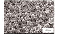
Hongkang Huang, Xia Luo, Yuhong Dai, Xin He, Yunzhong Liu, Bensheng Huang, and Zhou Fan
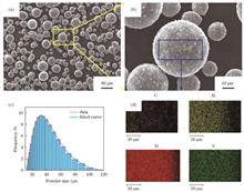
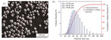
ObjectiveTitanium matrix composites have attracted considerable attention because of their high modulus of elasticity, high specific strength, high wear resistance, and excellent high-temperature durability. Most studies on titanium matrix composites (TMCs) focus primarily on the in-situ formed TiC reinforced composites. However, few studies have focused on the direct addition of TiC-reinforced titanium matrices. The manners in which the size, morphology, and distribution of TiC evolve during the SLM process and how they affect the microstructure and mechanical properties remain unclear. In this study, TiC/TC4 composites with directly added nanoscale TiC particles are successfully prepared by selective laser melting (SLM), and the microstructure evolution under different volume energy densities is investigated. Further, the TiC evolution during SLM and its influence on the microstructure and microhardness are analyzed. Thus, the findings of this study can provide the support for SLM preparation of titanium composites.MethodsHerein, nanoscale TiC (diameter of 50?150 nm) and TC4 are selected as the reinforced phase and matrix, respectively. The composite powder with TiC uniformly embedded on the surface of the TC4 powder is obtained by low-energy ball milling. Subsequently, the TiC/TC4 composites are prepared via SLM with different volume energy densities (29?97 J/mm3). The forming quality and microstructures at different volume energy densities are observed using optical microscopy (OM) and scanning electron microscopy (SEM) equipped energy disperse spectroscope (EDS). The grain size and crystal orientation are investigated using electron backscattering diffractometer (EBSD), and the phase compositions are measured using X-ray diffraction (XRD). Finally, the microhardness is measured using a digital microhardness tester.Results and DiscussionsThe optimized volume energy densities for the SLM formed TiC/TC4 composites are in the range of 50?70 J/mm3, with a relative density of 99.7% (Fig.3). Owing to the enrichment of TiC in the melt pool boundary zone, the microstructure of the composites exhibits a special double-sized grain distribution in the cross section (Fig.6). Owing to the rapid cooling characteristics of the SLM process, TiC cannot be sufficiently dissolved. Therefore, the SEM and EBSD results reveal three types of reinforcement: undissolved TiC, eutectic TiC, and precipitated TiC. Undissolved TiC is distributed primarily at the boundaries of coarse β equiaxed grains, eutectic TiC is distributed primarily in the boundaries of irregular eutectic β grains, and precipitated TiC is distributed primarily in the grains. With an increase in volume energy density, the chain-like eutectic TiC gradually transforms to rod-like eutectic TiC (Figs.7 and 8), the size of precipitated TiC inside the grain gradually increases, and the sizes of longitudinal and transverse α'-Ti gradually increase.ConclusionsThe optimal volume energy density for the formation of TiC/TC4 composites by SLM is 50?70 /mm3, and the relative density is 99.7% within this parameter range. TiC is enriched in the melt-pool boundary region under a strong temperature gradient and Marangoni convection. The microstructure of the composite has a special double-size grain distribution in the cross section, consisting of primary β equiaxed grains and irregular eutectic regions growing on the periphery. In the longitudinal section, the molten pool is a fish scale, and some chain structures exist in the molten pool that grow from the direction of heat flow to the horizontal direction. With an increase in volume energy density, the size of primary β equiaxed grains decreases, outer-ring irregular eutectic region expands, and morphology of fish scales becomes sharp. The microhardness initially decreases and then increases, essentially reaching 385?392 HV in the optimal molding process window. TiC in the composites is composed primarily of undissolved TiC (distributed near the primary β grain boundaries), eutectic TiC (distributed in the eutectic β grain boundaries in a chain or rod-like network), and precipitated TiC (distributed in the grain in a granular manner). With an increase in volume energy density, the difference in TiC size and quantity inside and outside the molten pool increases, chain distribution of eutectic TiC changes to rod, and the size of TiC in the grains increases. Further, no obvious orientation relationship between eutectic TiC and β-Ti is observed; however, a distinct orientation relationship between eutectic and in-grain TiC and α'-Ti exists: {11?20} α'-Ti∥{110}TiC.
Aug. 25, 2024Vol. 51 Issue 16 1602301 (2024)
Chao Xiang, Tao Zhang, Wenwei Wu, Zhihang Zou, Yongfei Sun, Jinpeng Liu, Xiaolei Xu, and Enhou Han
ObjectiveIn recent years, significant progress has been made in preparing conformal cooling dies for die casting using additive manufacturing technology. Among these advancements, 18Ni300 maraging steel has been widely applied because of its excellent forming characteristics. Currently, most research on selective laser melting (SLM) manufacturing of 18Ni300 maraging steel has primarily focused on the changes in microstructure after a heat treatment and the influence of precipitate phases on the strength, with limited emphasis on the impact of toughness. However, toughness plays a crucial role in determining the service life and safety of the molds.Although previous studies have explored reverse-austenite, systematic research on the toughness of 18Ni300 is currently lacking. Therefore, this study aims to systematically investigate the impact of the aging and solution temperatures on the microstructure and mechanical properties of 18Ni300 maraging steel. Additionally, it will specifically analyze the influence of reverse-austenite on the strength and plasticity of 18Ni300 maraging steel prepared using SLM technology. This study clarifies the relationship between the process, structure, and performance of 18Ni300 maraging steel, and proposes an optimal heat-treatment system. These findings offer valuable guidance for the practical application of this steel in various industries.MethodsIn this study, 18Ni300 powder was used as the raw material. Experimental samples were obtained through selective laser melting (SLM) using an appropriate method. Following the formation, the samples were subjected to various heat treatments. The bulk samples were ground and polished with sandpaper, followed by etching with a 4% nitric-acid solution in alcohol. The microstructure was examined using optical microscopy (OM) and scanning electron microscopy (SEM). The mechanically polished samples were additionally polished with SiO2 and the crystal structure of the material was analyzed using electron backscatter diffraction (EBSD). X-ray diffraction (XRD) was utilized to analyze the phase composition and determine its content. Finally, tensile tests were conducted at room temperature using a universal testing machine and the corresponding fracture surfaces were observed.Results and DiscussionsThe morphologies of the tested samples are shown in Figure 3. The printed sample displays distinct fish-scale-like fusion pools and lath martensite structures, whereas the honeycomb-like microstructure is not discernible in the SEM image. Following the aging treatment, the boundaries of the fusion pools in the samples become indistinct, and the boundaries of the honeycomb-like microstructure in the SEM image begin to dissolve. In the solution and aging-treated samples, the boundaries of the fusion pools vanish completely, and the martensite is transformed into a more refined structure. Additionally, the honeycomb-like microstructure observed in the SEM image also completely disappears.The XRD analysis of the samples reveals that the phase composition of the as-printed sample comprises martensite and residual austenite, whereas the aged sample consists of martensite, residual austenite, and reverse-austenite. Almost the entire microstructure of the solution- and aging-treated sample is composed of martensite. Figure 5 shows that the highest amount of reverse-austenite is observed in the aged sample. Furthermore, Table 3 indicates that the sample aged at 490 °C exhibits the highest content of reverse-austenite.The mechanical properties of the sample are closely correlated with the reverse-austenite content, as depicted in Figure 8. Notably, the sample aged at 490 °C exhibits greater toughness with only a marginal reduction in strength. However, the relationship between austenite and the strength toughness of 18Ni300 is not a simple linear correlation because of factors such as precipitates and the martensite morphology. Overall, it is evident that reverse-austenite significantly enhances the toughness and marginally decreases the strength. With an increase in the reverse-austenite content from 0.1% to 6.9%, the elongation after fracture improves by 72.5%, whereas the tensile strength decreases by 2.3%.ConclusionsThe printed samples of 18Ni300 maraging steel manufactured by SLM display a distinct molten pool and a microstructure comprised of coarse martensite and a small proportion of residual austenite. Following the aging treatment, a ductile phase called reverse-austenite is generated. After the post-solution and aging treatments, the microstructure exhibits uniform and dense plate-like martensite with no notable presence of the austenite phase. A direct aging treatment at 490 °C is considered the optimal heat-treatment process for achieving an ideal balance between strength and toughness. At this temperature, the microstructure exhibits the highest reverse-austenite content (volume fraction: 7.7%). The ultimate tensile strength is 2012.8 MPa, and the elongation after fracture reaches a peak value of 6.9%. Therefore, a direct aging treatment at 490 °C is regarded as the most optimal heat-treatment process.The fine reverse-austenite within the maraging steel manufactured via SLM serves as a toughening phase, enhancing the toughness without significantly compromising the strength. With an increase in the reverse-austenite volume fraction from 0.1% to 6.9%, the elongation after fracture experiences a 72.5% improvement, albeit at the expense of a 2.3% decrease in the ultimate tensile strength. Thus, the reverse-austenite is advantageous for achieving exceptional overall mechanical properties in maraging steel manufactured via SLM. The fine reverse-austenite plays a pivotal role in enhancing themaraging steel. However, in the maraging steel manufactured via SLM using 18Ni300, precipitation strengthening constitutes the primary mechanism with a limited effective range of precipitation temperatures. Further research is necessary to increase the reverse-austenite content, while maintaining adequate precipitation strengthening.
Aug. 25, 2024Vol. 51 Issue 16 1602302 (2024)
Kailiang Yang, and Huaixue Li
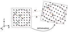
ObjectiveEffective prediction of residual stresses and deformations can ensure the quality of metal additive-manufactured parts. The traditional mesh-based finite element method (FEM) has been able to model many additive manufacturing processes with a correspondingly high fidelity. However, it is still deficient in other areas such as the simulation of complex boundary conditions, large deformations and crack extensions, interfacial motions, and phase transitions. Peridynamic, a nonlocal continuum theory whose governing equations are in the form of integral-differential equations, has the advantage of addressing the phenomenon of discontinuities. Numerous reports have been published on the evolution and application of the peridynamic theory after years of development. In this study, a three-dimensional peridynamic model is introduced to simulate the temperature field and deformation during laser additive manufacturing.MethodsThe basic thermophysical processes of laser additive manufacturing are considered in the peridynamic model. These include the coupling of thermal, material, and heat source models. First, the bond-based peridynamic governing equations are provided, including the coupled thermo-elasticity equation of motion and thermal diffusion. The time integration of the peridynamic motion and thermal diffusion equation is obtained by employing explicit forward and backward differences and forward difference techniques to obtain the velocity, displacement, and temperature, respectively. The simulation program is then created using the simulator generation system DELAB, which is used for calculating and analyzing the physical system of the particles. The Gaussian heat source and phase-change models in the heat transfer scenarios are used for the laser additive manufacturing process. In addition, a peridynamic volume correction procedure is considered. Finally, the model is validated for several individual physical processes, including the heat transfer model of the block and heating sphere model. The results indicate that the model is stable and accurate. This is expected to be used to simulate the laser additive manufacturing process.Results and DiscussionsA peridynamic model is demonstrated for simulations of the single-layer selective laser melting process. For the moving Gaussian heat source model with a 2-dimension plate, temperature and displacement variations along the x-direction are considered during the process. The high gradient temperature near the heat source is clearly displayed with the movement of the heat source in the x-direction (Fig. 13). The maximum displacement of the plate increases with the movement and constant action of the heat source (Fig. 14). The effect of the phase change on the temperature variation is presented, which shows that the maximum temperature is lower than the situation when phase change due to latent heat is considered (Fig. 16). For the single-layer powder bed model, a circular trajectory of the heat source is considered. The temperature field distribution at different times shows the shape of the melt pools at different trajectory locations (Fig. 18). A similar finite element model is created to verify the temperature field in the peridynamic model. The peridynamic-predicted results of the temperature variation at points P1, P2, and P3 are in good agreement with the FEM model results obtained using ANSYS (Fig. 20).ConclusionsWe present a three-dimensional peridynamic model to simulate the temperature field and deformation during laser additive manufacturing. The basic thermophysical processes of laser additive manufacturing are considered in the model. These include the coupling of thermal, material, and heat source models. The model is validated for several individual physical processes. The obtained results show that the model is stable and accurate; the model can be used to simulate the laser additive manufacturing process. Finally, the peridynamic model is demonstrated for simulations of the single-layer selective laser process. Although this model has not been experimentally validated, it is a novel solution for simulating laser additive manufacturing. We expect that further studies based on this model will produce more feasible solutions to problems in the additive manufacturing process. Future efforts should utilize the peridynamic theory to overcome the difficulties in the simulation of laser additive manufacturing while considering the high-fidelity simulation with the traditional finite element method.
Aug. 25, 2024Vol. 51 Issue 16 1602303 (2024)
Siyuan Zhang, Youzhao Zhang, Xiangwei Li, Tao Zhang, Chao Yuan, and Shuyan Zhang
ObjectiveSelective laser melting (SLM) technology offers a wide range of design freedom, high density, and strong metallurgical bonding; thus, it is highly suitable for processing workpieces with complex shapes. A conformal cooling mold formed via SLM can improve the cooling efficiency and decrease the injection cycle time. However, only a few types of mold steel materials are suitable for 3D printing because of long processing time and high costs. First, conventional processes can be employed to manufacture conventional parts; subsequently, complex parts can be built using SLM. With this approach, the manufacturing efficiency can be improved and costs can be reduced. In this study, a new type of 3D printing die steel material (AM40) is deposited on a commercial H13 substrate using SLM. The effects of heat treatment (HT) on the microstructure and mechanical properties of AM40/H13 bimetallic structural materials are studied, and the deformation and cracking behaviors of the bimetallic molds are revealed.MethodsIn this study, AM40 steel powder and annealed H13 steel sheets are used. SLM is used to deposit AM40 onto the H13 substrate. Subsequently, quenching and tempering are performed to study the effects of the heat treatment. The particle size distribution is characterized using a laser particle size analyzer, whereas the microstructure and fracture morphology are characterized using optical microscope (OM) and scanning electron microscope (SEM). The grain morphology, orientation, and local misorientation of the bonding interface are characterized using electron backscatter diffraction (EBSD). Additionally, a Vickers microhardness tester is employed to measure the microhardnesses of the as-built and heat-treated samples. Tensile tests are performed using a fatigue testing machine.Results and DiscussionsNo crack defect is observed at the interface of the as-built AM40/H13 bimetallic structure and the unique Marangoni molten pool at the interface (Fig. 7). Moreover, fine cellular and columnar martensite structures are observed in the AM40 region (Fig. 8). The microstructure of H13 is coarsened austenite (Fig. 5), and the distinct microstructural inhomogeneity is observed at the bonding interface. After quenching and tempering, the characteristics of the molten pool disappear, and uniform lath martensite microstructures form in the H13 region (Fig. 8). The inhomogeneity of the grain size and misorientation at the interface are eliminated (Fig. 10). Moreover, the diffusion width of element at the interface increases from 440 μm to 500 μm (Fig. 9). Additionally, the hardness of the as-built AM40/H13 at the bonding interface is 642 HV, which is higher than those of AM40 (529 HV) and H13 (202 HV). The average hardness of HT-AM40/H13 at the bonding interface decreases to 480 HV (Fig. 11), thus indicating that the hardness difference between AM40 and H13 is eliminated by the heat treatment. The tensile strength of HT-AM40/H13 increases significantly from 644 MPa to 1436 MPa (Fig. 12). Furthermore, some dimples, along with a cleavage pattern, are observed in the fracture (Fig. 14), thus indicating that the fracture mode is a combination of ductile and brittle. The increase in the tensile strength and ductility of the heat-treated AM40/H13 bimetallic alloy is analyzed based on the microstructure and fracture morphology of the bonding interface.ConclusionsIn this study, the as-built AM40/H13 bimetallic structure does not exhibit crack defects at the interface, and the microstructure is heterogeneous. Marangoni convection and cellular and columnar structures are observed in the weld pool at the interface. The alloying elements are evenly distributed at the interface, thus indicating good metallurgical bonding. After heat treatment, the grain size and dislocation density near the interface are similar, thus eliminating the inhomogeneity of the interface structure. The elements at the interface diffuse, and the diffusion width increases by 60 μm. The hardness at the as-built AM40/H13 bimetallic H13 side is the lowest (202 HV), followed by that at the AM40 side (529 HV); by contrast, the interface hardness is the highest (642 HV). Tensile deformation and cracking of the bimetal preferentially occur at the H13 side, with a strength of 644 MPa and fracture elongation of 29%, thus indicating ductile fracture. After heat treatment, the hardness of H13 increases to 483 HV, which is equivalent to that of AM40 (479 HV) after heat treatment, and the inhomogeneity of the hardness is eliminated. In addition, the tensile strength of HT-AM40/H13 increases significantly from 644 MPa to 1436 MPa, which is between those of AM40 and H13. The fracture is preferentially located at the AM40 side, far from the interface. Further, some dimples and cleavage patterns are observed, thus indicating that the fracture mode is a combination of ductile and brittle.
Aug. 25, 2024Vol. 51 Issue 16 1602304 (2024)
Yiqun Ren, Yuechen Wu, Shuai Chang, Liqun Li, and Minqing Wang
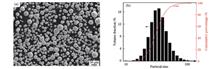
ObjectiveLaser melting deposition is used to prepare ATI 718Plus samples to study the effects of three heat treatment regimes on their microstructure evolution, hardness, and room temperature tensile properties. These regimes include direct aging heat treatment, solutionizing and aging heat treatment at 982 ℃, and high-temperature solutionizing and aging heat treatment at 1020 ℃. The aim is to elucidate the phase transformation behavior and mechanical property changes of laser additive ATI 718Plus under different heat treatment regimes and provide guidance for the selection of heat treatment processes used in the laser additive manufacturing of ATI 718Plus.MethodsThe plasma rotating electrode process is used with ATI 718Plus powder with particle diameter of 45?105 μm to prepare wrought ATI 718Plus superalloy substrates. The experiments are performed on the laser additive manufacturing system shown in Fig. 2, which consists of a 4000 W continuous wave fiber laser, an inert atmosphere processing chamber, a coaxial nozzle, and a powder feeding device. A well-formed ATI 718Plus sample is prepared using a unidirectional reciprocating scanning method with the following parameters: a laser power of 1200 W, scanning speed of 0.8 m/min, protective gas flow rate of 10 L/min, carrier gas flow rate of 15 L/min, and powder feed rate of 13 g/min. The geometric dimensions of each sample are 50.0 mm×58.0 mm×2.5 mm. Three heat treatment regimes are employed, as shown in Fig. 2(b). The analyzed samples are mechanically ground with SiC paper and polished using diamond suspensions and a colloidal silica suspension to prepare metallographic samples. Then, the polished samples are etched with No.2 waterless Kailing's reagent for optical microscope and scanning electron microscope (SEM) investigations. Uniaxial tensile tests are carried out at room temperature using a universal testing machine with a constant displacement rate of 1 mm/min.Results and DiscussionsAfter laser deposition, a large number of Laves phase areas form in the interdendritic region (Fig. 3). This hard and brittle phase deteriorates the mechanical properties of the additive-manufactured ATI 718Plus samples. The as-deposited sample mainly exhibits an epitaxial growth columnar dendritic morphology, with a large number of brittle long-chain Laves phases precipitated between dendrites, which consumes a significant amount of Nb, Mo, and other strengthening elements, severely reducing the mechanical properties of the as-deposited sample. After the direct aging heat treatment, the long-chain Laves phase morphology remains unchanged, and the η and γ′ phases precipitate heavily between dendrites. The solution and aging heat treatment system can effectively reduce the size and content of the Laves phase. With an increase in the solution temperature, the size and content of the Laves and η phases gradually decrease, and the γ′ phase uniformly precipitates. The hardness significantly increases after heat treatment (Table 2), but the hardness differences between the three heat treatments are relatively small. The room temperature tensile properties are shown in Fig. 8. Compared to the as-deposited sample, after heat treatment the samples exhibit significant increases in both the yield strength and tensile strength, while the elongation at fracture decreases and then increases. The yield and tensile strengths increase by 67.7% and 51.9% after the direct aging heat treatment, respectively, while the elongation at fracture decreases by 13%. After the solution aging (SA) heat treatment at 982 ℃, although the strength improvement is not as significant as that after the direct aging treatment, the yield and tensile strengths still increase by 63.6% and 45.6%, respectively. At the same time, the elongation at fracture increases by 3% compared to that of the as-deposited state. The strength improvement is the smallest after the 1020 ℃ SA, with a yield strength increase of only 62.0% and tensile strength increase of 34.2%, but the plasticity is significantly improved, with an elongation at fracture increase of 25.8% compared to that of the as-deposited state.ConclusionsThe strength and hardness values of the ATI 718Plus additive samples significantly increase after heat treatment. The best match between strength and plasticity is obtained after high-temperature solution and aging heat treatment at 1020 ℃. Compared with those of the as-deposited state, the tensile strength and elongation at the fracture of the sample increase by 34.2% and 25.8%, respectively, after the 1020 ℃ solution and aging heat treatment.
Aug. 25, 2024Vol. 51 Issue 16 1602305 (2024)
Jintang Chen, Kai Zhang, Tingting Liu, Zhiyong Zou, Jiansen Li, Huiliang Wei, and Wenhe Liao
ObjectiveLaser powder bed fusion (LPBF) is an additive manufacturing (AM) process that has the advantages of forming complex-shaped parts and cutting costs. It is widely used in the aerospace, medical equipment, weapons manufacturing, and other industries. However, in the LPBF process, the material powder is repeatedly heated and melted under the effect of laser energy and then cooled and solidified, which facilitates the formation of a large thermal gradient and thermal stress in the parts, leading to warping deformation. This type of deformation significantly affects the dimensional accuracy and mechanical properties of parts. By combining sensor signal acquisition with data analysis, deformation defects can be detected during AM to reduce production costs and improve the quality of formed parts. The radiant light signal of the molten pool is sensitive to the thickness of the powder layer during the LPBF process, which may reflect the warping deformation that has already occurred. It is also correlated with the temperature of the molten pool, reflecting the peak temperature at that location, and is related to the temperature field of the sample. Therefore, it has the potential to monitor the thermal stress during warping deformation. To study the relationship between thermal stress-induced warping deformation and the radiant light signal of the molten pool, a method for monitoring warping deformation in the LPBF process by acquiring the radiant light signal of the molten pool is explored in this study. In this study, an overhanging sample is formed during the experiment, and the radiation signal of the molten pool is collected and analyzed. The results show that the radiant light signal can not only monitor warping deformation but also reflect formation process of warping deformation to a certain extent.MethodsTo collect and compare the radiation light signal of the molten pool during the forming process of the warped and normal samples, T-shaped overhanging structure samples are formed (Fig.2), and five samples with three different support structures and sizes are designed for the experiment (Table 1). In this process, three sensors collect the radiation intensity signals from the molten pool, and an upper computer records the coordinate data of the laser spots (Fig.1). After data alignment, each light intensity value corresponds to the coordinates of the laser spot during scanning. To further explain the variation trend of the light intensity signal along the long side (Y-direction) of the sample, the scanning section of the sample is divided into regions, and the average light intensity of each region is calculated. Three measurement points are selected on the sample, and the heights of the measurement points relative to the substrate plane are measured using a coordinate apparatus.Results and DiscussionsNo evident warping deformation is observed in the forming process of samples S80-1 and S80-2, whereas the warping deformations of samples S25-1, S25-2, and S20 are larger (Fig.6). This result indicates that samples with smaller support areas are prone to warping deformation; however, no noticeable linear correlation is observed. The normal samples S80-1 and S80-2 produce a larger average light intensity at both ends, with a minimum value of 0.93 V, while warped samples S25-1, S25-2 and S20-1 produce lower light intensity at the same area (Fig.7). This phenomenon indicates that sample warping can be distinguished from the light signal of the molten pool. The light intensity distribution of the first overhanging layer is different between the warped and normal samples. The light intensity of the warped sample in the region where the corresponding lower layer is solid is significantly higher than that in other regions, forming a “wave peak” in the curve (Fig.8). The above phenomena indicate a correlation between the radiant intensity distribution and peak temperature at the corresponding position and reveal that the evolution trend of the light intensity between the layers of the samples with the same geometric structure. The light intensity of the normal sample fluctuates more between layers, whereas that of the warped sample fluctuates less (Fig.9).ConclusionsIn this study, three types of overhanging samples with different structures are formed, and the radiation light signal of the molten pool is collected. Combined with sample deformation measurements and statistical methods, the data are analyzed, and the following conclusions are obtained:1) In the layer after warping deformation, the light intensity of the warped specimen decreases significantly in the warped region, while the distribution of the light intensity of the normal specimen is uniform without a notable gradient.2) For the warped specimen, when the overhanging layer has just been formed, and the deformation has not yet occurred, the light intensity "crest" corresponding to the central solid region of the specimen is quite different from the light intensity in other regions of the layer.3) The interlayer evolution trends of the light-intensity values of the warped and normal samples are different. With an increase in the number of formed layers, the influence of the overhanging structure on the light intensity signal gradually decreases, and the light intensity tends to stabilize after the fifth layer.4) A sample with a smaller support area is more likely to produce warping deformation, but no notable linear correlation exists between these two factors.
Aug. 25, 2024Vol. 51 Issue 16 1602306 (2024)
Shuguang Yao, Yunhui Dong, Xianglong Li, and Minhan Xie
ObjectiveThe parameters for selective laser melting (SLM) directly affect the morphology and microstructure of the melt-forming process, which in turn affect the mechanical properties of the formed structure. Metal powder rapidly heats up and melts under high-speed laser irradiation, forming a metal molten pool. The complex heat and material exchange processes inside and outside the molten pool are difficult to detect in real-time using monitoring instruments. To address the defects generated during the SLM forming process of an AlSi10Mg alloy, this study employed experimental and numerical simulation methods to investigate the effects of forming parameters such as laser power and scanning speed on the morphology of single- and double-channel of the AlSi10Mg alloy.MethodsFS271M laser selective melting equipment was used for single- and double-channel SLM forming of the AlSi10Mg powder. The aluminum substrate was preheated to 130 ℃, the forming cavity was filled with high-purity argon gas as a protective gas, and the oxygen volume fraction was controlled to be less than 0.15%. Table 2 lists the forming parameters. The melt length was set to 20 mm. To facilitate subsequent observation, 1 mm spacing was set for single-melt scanning, and the forming process was repeated five times. After forming and cooling, the morphology of the melt was observed and analyzed using an AM7031MT digital microscope. In addition, Flow-3D v11.1 software was used to simulate the single-channel laser selective melting forming process. A numerical simulation was conducted to investigate the physical effects and phenomena such as thermal radiation, heat conduction, solid-liquid phase transition, molten pool evaporation, gravity, surface tension, and the Marangoni effect derived from the SLM process.Results and DiscussionsUnder different scanning speeds using a laser power of 300 W, the overall continuity of the formed melt is good, no obvious spheroidization is observed, and the degree of overlap is high. As the laser-scanning speed decreases, the width of the melt gradually increases, and a clear ripple morphology is generated at a scanning speed of 700 mm/s. When a 100 W power laser is used for melt forming, the discontinuity and spheroidization of the melt are more severe. The width of the laser heat-affected zone decreases with an increase in the laser scanning speed. The lower the scanning speed, the more obvious is the degree of oxidation and blackening of the powder molten pool. The oxidation effect of the AlSi10Mg powder during processing is a major reason for the low density of the formed structural components. In practical experiments and production, the first-layer premelting method can be adopted to consume as much residual oxygen in the cavity as possible, reducing negative oxidation effects during the molding process. Under the action of a low scanning speed and high energy density laser, the spattering and airflow of the molten pool become more intense, making it easier to produce small-particle spheroidization defects on the forming plane. The keyhole depth generated by the metal molten pool under steam recoil pressure can reach 100 μm. As the laser moves, the molten pool rapidly cools and solidifies due to the high thermal conductivity of the aluminum alloy materials. If the keyhole is not completely filled by the molten pool fluid, pore defects form. Therefore, avoiding keyhole generation while ensuring the continuity of the melt path is necessary. The discontinuity of the melt path is mainly caused by insufficient melting of the powder layer. Reducing the thickness of the powder layer can improve the discontinuity caused by insufficient energy. However, the selection of SLM forming parameters should consider the product-forming efficiency while ensuring the quality of structure forming. Reducing the thickness of the powder layer prolongs the structure-forming time and affects the forming efficiency, and increasing the preheating temperature reduces the energy required for melting. To investigate the effects of the preheating temperature on the morphology of the formed channel, a laser power of 100 W and scanning speed of 800 mm/s were selected as scanning process parameters, and the preset environmental temperature T0 was gradually increased for calculation. At T0=500 K, the discontinuity phenomenon in the forming area is eliminated.ConclusionsThis study investigated the single-layer melt forming of AlSi10Mg powder material through experimental and numerical simulation methods. It was found that the surface tension and melt recoil pressure play crucial roles in the evolution and motion of the molten pool. Even when high-purity argon gas is used as the protective gas for the experiment, because of the oxidizability of the AlSi10Mg material, residual oxygen still affects the quality of the melt forming. Therefore, the oxygen content in the forming cavity should be minimized as much as possible prior to forming. Because the AlSi10Mg alloy powder has a weak laser absorption ability, the energy absorption rate was set to 12% in this study. For a given powder bed with a thickness of 50 μm, a mobile laser beam with a linear energy density of 200 J/m is required to completely melt the powder layer. Under low-power 100 W laser scanning, because of the low energy density of the laser, the melt channel is prone to discontinuity and large-scale spheroidization. Increasing the input energy density by reducing the scanning speed does not effectively solve the problem of uneven melt channels. Obtaining a smoother filling in the keyhole formed under low-speed scanning is difficult, which reduces the quality of the melt channel formation. By increasing the preheating temperature, the laser line energy density required for melting can be reduced, and the morphology of the melt formed at low power can be improved.
Aug. 25, 2024Vol. 51 Issue 16 1602307 (2024)
Haisheng Zhao, Feng Zhang, Chengchao Du, Xudong Ren, Xiangyu Wei, and Junjie Gao
ObjectiveIn recent years, laser additive manufacturing based on direct laser deposition has attracted widespread attention because of its flexibility and efficiency. This technology has a wide range of applications and high additive manufacturing efficiency. It is widely used in the aerospace, rail transit, and ship component maintenance equipment fields. However, high-strength aluminum alloys such as those in the Al-Zn-Mg-Cu series have a high content of alloying elements. During the solidification process, the semi-solid range of the alloy may exceed 100 ℃, which can easily leave gaps between aluminum grains. The α-Al layer of "liquid film" generates cracks under the action of thermal stress, making laser deposition repair difficult. AlSi10Mg alloy, as a cast aluminum alloy, has the characteristics of a short semi-solid range and high strength, and is suitable for additive manufacturing and the laser repair of high-strength aluminum alloy components. However, during the laser deposition process, process fluctuations often cause defects such as pores to appear in the components, leading to cracks and ultimately component failure during use. Therefore, exploring a method to eliminate pores in components produced using AlSi10Mg laser deposition is of great significance for improving the mechanical properties and service life of AlSi10Mg components.MethodsAtomized AlSi10Mg alloy powder with a particle size ranging from 53 μm to 150 μm is adopted. During the laser deposition process, the laser power is 2700 W, deposition speed is 600 mm/min, powder feed rate is 5.8 g/min, overlap amount is 2.5 mm, argon flow rate is 5 L/min, and protective argon amount is 20 L/min, resulting in a single-layer thickness of 0.5 mm. After depositing eight layers to achieve a thickness of 4 mm, stir friction treatment is performed on the deposited AlSi10Mg alloy. The height of the mixing needle of the mixing head is 4 mm, with a four-prism shape and diameter of 6 mm at the end of the prism. During the stirring friction treatment process, the rotational speed is 800 r/min, stirring speed is 100 mm/min, and variation in the stirring friction treatment passes is 5 mm. Subsequently, the laser deposition of eight-layer AlSi10Mmg alloy is continued on the surface of the AlSi10Mg alloy after the stir friction machining, and then stir friction machining is used.Wire cutting is used to cut the AlSi10Mg alloy into five samples, and stir friction-assisted laser deposition is conducted, followed by room-temperature rolling treatment. Rolling deformation values of 20%, 46%, and 68% are achieved on three of the samples. The five tensile specimens of the AlSi10Mg alloy are treated as mentioned above, and their strength and elongation values are measured using a tensile testing machine. After vibration polishing, the five metallographic samples are observed using a scanning electron microscope and backscattered electron diffractometer, and their microhardness values are measured. A thin film sample of the AlSi10Mg alloy is prepared and its microstructure is observed using a transmission electron microscope after electrolytic double spraying. The fracture of the tensile specimen is observed using the scanning electron microscope.Results and DiscussionsThe hardness values of the AlSi10Mg alloy in the five different states are listed in Table 1. It can be observed that the hardness of the deposited AlSi10Mg alloy is approximately 109 HV. Because at high temperatures, the solid solubility of the Si element in the α-Al matrix is relatively high, and when the temperature rapidly drops, it is difficult for the Si element to recover from α-Al matrix, and a large number of Si atoms on α-Al matrix play a role in solid solution strengthening. The Al matrix plays a role in solid solution strengthening. After stir friction processing, the solid solution strengthening effect is significantly weakened, and the hardness of the AlSi10Mg alloy decreases to 75 HV. Based on the hardness values of the rolled AlSi10Mg specimens listed in Table 2, it can be observed that the rolling process improves the effects of dislocation strengthening and fine grain strengthening in the AlSi10Mg alloy, ultimately increasing the hardness of the laser-deposited AlSi10Mg alloy after stir friction processing to 116 HV. As shown in Fig. 9, after stir friction processing, the strength of the AlSi10Mg alloy is close to 200 MPa, and the elongation distribution is 33%?40%. It can be seen that stir friction processing can simultaneously improve the strength and plasticity of the laser-deposited AlSi10Mg alloy. Figure 10 shows that there are a large number of dimples in the tensile fracture surface of the AlSi10Mg alloy in the laser deposition state and stir friction processing state, indicating that the fracture mode of both AlSi10Mg alloy specimens is the plastic fracture mode. The research on hardness shows that the strength and elongation of the laser deposited AlSi10Mg alloy cannot reach high levels. However, after stir friction processing, the larger shoulder pressure and stirring effect eliminate the porosity defects in the alloy, reduce the stress concentration, and thus significantly increase its elongation.ConclusionsAfter friction stir processing, the columnar α-Al and eutectic phases in the laser deposited AlSi10Mg become equiaxed α-Al grains and Si particles, while the Mg2Si precipitate phase is significantly refined. After rolling, when the deformation of the AlSi10Mg alloy increases to 68%, dislocation strengthening further refines the grains.After rolling, the dislocation strengthening effect in the alloy is significantly enhanced. In addition, increasing the rolling amount also brings about a fine grain strengthening effect. Therefore, the hardness of the AlSi10Mg alloy can be increased to 116 HV at most, exceeding the microhardness of the laser deposited AlSi10Mg alloy.Although the solid solution strengthening effect in the laser deposited AlSi10Mg alloy is remarkable, the solidification defects in the alloy lead to the formation of early cracks during the tensile process, which results in an alloy strength of less than 200 MPa and an elongation of less than 20%. After friction stir processing, the strength and toughness of the AlSi10Mg alloy are simultaneously improved, with a strength close to 200 MPa and an elongation of 33%?40%. After rolling, the dislocation strengthening effect of the AlSi10Mg alloy gradually increases, and its strength continues to rise, reaching a maximum of approximately 400 MPa. The localized hardening area in the alloy leads to a decrease in its plastic deformation ability, and the elongation gradually decreases to 25%.
Aug. 25, 2024Vol. 51 Issue 16 1602308 (2024)
Caiwang Tan, Shijia Wang, Jianhui Su, Xiaohui Han, Bo Chen, and Xiaoguo Song
ObjectiveHybrid material structures have various applications in the automotive industry owing to their light weight. Stainless steel, which exhibits good corrosion resistance and remarkable mechanical properties, is widely used in automotive applications. Glass fiber reinforced plastics (GFRPs) that exhibit high specific strength and cost performance have replaced existing materials in applications requiring lightweight materials. Single-side resistance spot welding of stainless steel and GFRP can help combine the advantages of the two materials. However, owing to the difference in the thermal physical properties and chemical structures of these two materials, the combined strength cannot meet industrial requirements. Improving mechanical interlocking and chemical bonding is an effective approach for enhancing the joint performance. The laser joining process can be used to fabricate micro-textures and change the surface chemical state. Thus, micro-textures on the surface of stainless steel are prepared using a nanosecond laser, and the strengthening mechanism of the interface under the influence of the micro-textures is studied.MethodsInitially, 304 stainless steel and GFRP are selected as base materials. The 304 stainless-steel sheets are subjected to laser texturing. The cruciform mesh micro-texture is selected as the basic morphology of the stainless-steel surface. The grid line uses contained multiple equally spaced scan lines, and a laser processing system supporting software is used to preset different micro-texture widths. The number of laser scanning times is set as 10, and the micro-texture width is set as 0.1?0.5 mm. An optical digital microscope and a field-emission scanning electron microscope are used to detect the laser texture, surface morphology, and fracture surface of the joint. A constant-temperature heating platform and a high-temperature wetting angle measurement system are used to measure the GFRP contact angle on the stainless-steel surface to characterize its wettability. A universal material testing machine is used to conduct tensile-shear tests on the 304 stainless steel/GFRP single-side resistance spot welding joints.Results and DiscussionsThe introduction of micro-textures on the surface of stainless steel significantly improves the wettability of the surface. The surface of stainless steel changes from an untreated non-wetting state to a wet state after laser treatment. As the width of the micro-texture increases, the wettability initially increases and then decreases (Fig. 5). When the micro-texture width is 0.2 mm, the wettability reaches the optimum value. The interior of the micro-textures is completely filled with molten GFRP. When the micro-texture width is too large, the molten GFRP cannot completely fill the interior of the micro-textures (Fig. 7). C and Fe diffuse at the interface, and an element diffusion layer is formed (Figs. 8 and 9). When the micro-texture width is 0.2 mm, the tensile-shear force reaches the maximum value of 3548 N, which is 385% higher than that of the untreated stainless steel/GFRP single-side resistance spot welding joint. The tensile-shear force first increases and then decreases as the micro-texture width increases. Compared with the case of the joint without micro-textures, after laser treatment of the stainless-steel surface, a large amount of the resin-glass fiber mixture is observed in the center area of the fracture of the joint (Fig. 11). The fracture mode changes from an interfacial fracture to a mixed form of interfacial and cohesive fractures. Corresponding to the wettability and joint tensile-shear force, the bonded-area ratio first increases and then decreases, indicating an improvement in mechanical properties.ConclusionsLaser texturing is used to improve the performance of stainless steel/GFRP single-sided resistance spot welding joints. After the nanosecond laser treatment, the wettability of the molten GFRP on the stainless-steel surface is significantly improved, and the state changes from non-wetting to wetting. The introduction of the micro-textures improves the mechanical properties of the stainless steel/GFRP resistance spot welding joint. When the micro-texture width is 0.2 mm, the tensile-shear force of the stainless steel/GFRP single-side resistance spot welding joint reaches the maximum value of 3548 N. Compared to the case wherein the micro-textures are not introduced, the tensile-shear force of the textured joint is 731 N. The introduction of the micro-textures increases the contact area between the stainless steel and GFRP, thereby significantly enhancing mechanical interlocking. When the micro-texture width is suitable, the GFRP completely fills the inside of the micro-textures. When the micro-texture width is too small or too large, the GFRP does not completely fill the inside of the micro-textures owing to the influence of wettability. In addition to mechanical interlocking, Fe and C chemically diffuse at the interface to form a compound layer, which further improves joint strength.
Aug. 25, 2024Vol. 51 Issue 16 1602101 (2024)
Shuaishuai Chen, Wendong Zhang, Xianghuan Liu, Qiyun Chen, Boyang Li, Shuanghao Cui, Liming Liu, and Hongyang Wang
ObjectiveDuctile iron has been extensively used in various automotive components such as crankshafts and differential housing owing to its relatively low density and capacity for significant tensile strength. 20MnCr5 is a robust and tough alloy steel commonly employed in the production of gears and shafts. Establishing effective welding between the shaft body and the gear material is a significant research challenge. However, the notable disparity in the thermal properties between ductile iron and alloy steel hinders the performance of the welding joint. The high carbon content of ductile iron promotes carbon segregation at the welding interface and exacerbates the formation of microcracks, thereby considerably increasing the complexity of the welding process. Owing to its high energy density, laser welding offers the advantage of generating welds with more precise heat-affected zones. In this study, a novel continuous-pulse coaxial dual-beam laser is employed as a welding heat source to enhance the surface quality of the weld seam. The high-quality welding of ductile iron and alloy steel is achieved by decreasing the laser input power and diminishing pore formation. We hope that our novel welding strategy and findings will be helpful in understanding the bonding mechanism of ductile iron and alloy steel and provide more application space for their connectors.MethodsIn this study, QT500-7 and 20MnCr5 are employed as the base materials, with ERNiCr-3 as the filling wire. A novel continuous-pulse dual-beam laser is used as the heat source. First, the pulsed laser power is varied with a constant continuous laser power to determine the optimal combination of heat sources. The laser action position is then adjusted to further enhance the weld strength. Microstructures are observed using a metallographic microscope, and mechanical performance testing and analysis are conducted using a tensile testing machine. The microhardness of the weld is measured using a microhardness tester. Additionally, the fracture behaviors of different specimens are analyzed using a field-emission scanning electron microscope.Results and DiscussionsThe use of a continuous-pulse coaxial dual-beam laser as a welding heat source (Fig. 2) produces high-quality welding joints. When the pulsed laser power is varied, the weld formation varies considerably (Fig. 4). The weld seam is found to have no defects, such as cracks or pores. When the laser action position shifts toward the steel side, the heat input on the ductile iron side gradually decreases. This reduction in the heat input suppresses the diffusion of carbon, leading to a significant decrease in the hardness values of the heat-affected and bond zones on the QT500 side (Fig. 13). The cross-sectional morphology of the weld reveals significant changes in the melting amount of the QT500-7 side base material, with the centerline shifting toward the ductile iron side when the laser action position is changed (Fig. 6). The segregation line of carbon caused by the high carbon content of the nodular cast iron is solved by changing the laser position to reduce the heat input on the side of the nodular cast iron (Fig. 7). The best mechanical properties of the joint are obtained under a pulsed laser power of 440 W and offset of 0.2 mm. In summary, a continuous-pulse coaxial dual-beam laser can yield high-quality welding joints. Better dual-beam laser welding parameters can be achieved by adjusting the laser power and action position. Furthermore, carbon segregation issues can be effectively resolved by reducing the heat input on the side of the nodular cast iron by changing the laser action position, and pulsed laser stirring proves useful.ConclusionsIn this study, a coaxial dual-beam laser welding technology is proposed to address the challenges of welding ductile iron QT500 and alloy steel 20MnCr5. The main problems are the precipitation of martensite and ledeburite in the heat-affected and bond zones on the QT500 side, which results in carbon segregation. The pulsed laser power and position are adjusted in this study. When the laser action position is shifted toward the steel side, the decreased heat input suppresses the diffusion of carbon, leading to a significant decrease in the hardness of the heat-affected and bond zones on the QT500 side. The best mechanical properties are achieved under a pulsed laser power of 440 W and laser offset of 0.2 mm. The continuous-pulse coaxial dual-beam laser welding technology not only improves the carbon segregation phenomenon on the ductile iron side but also reduces the formation of welding cracks. Overall, the proposed novel coaxial dual-beam laser welding technology is effective in improving welding quality, specifically for ductile iron and alloy steel dissimilar metals. The joint exhibits high-quality and high-performance characteristics by reducing carbon segregation and minimizing hardness values. This study advances the field of welding and provides a potential solution for the welding of dissimilar metals with different material properties.
Aug. 25, 2024Vol. 51 Issue 16 1602102 (2024)
Lei Wu, Yukun Chu, Honggang Yang, and Yunxia Chen
ObjectiveOwing to the influence of manufacturing processes and welding environments, aluminum alloy materials, are prone to various internal welding defects during the welding process, such as pores, slag inclusions, and incomplete penetration. Currently, defects in DR (digital radiography) weld seam images are typically manually identified by trained professionals. However, the manual detection of DR ray film defects has a high workload, low efficiency, and problems with false positives and missed detection. With the rapid development of computer and digital image-processing technologies, deep learning is widely used in object recognition. The current target detection algorithms exhibit sub-optimal performance in accurately detecting weld defects. Furthermore, enhancement of the detection accuracy of the model often comes at the cost of decreased speed and increased parameter count. This in turn hinders effective deployment. To address this issue in the defect detection of aluminum alloy weld DR images, a lightweight weld defect detection algorithm based on YOLOv8 is proposed. This improved algorithm effectively resolves the problems associated with increased parameter counts and reduced detection speeds resulting from model enhancement.MethodsFirst, the SimAM module was added to C2f to improve the overall network performance. The specific approach is introducting the SimAM module into the bottleneck module of the C2f module (Fig.4). This can improve the feature expression ability of the module without increasing the number of model parameters. The loss function was then replaced with the WIoU loss function to improve the quality of the anchor frame, and the first-layer convolution module was replaced with the Focus convolution module to increase the detection speed while increasing the network sensory field. These improved the detection effect on small targets. The YOLOv8 model underwent consistent parameter and indicator during model enhancement. This in turn ensured the effectiveness of the improvement points by comparing all indicators across the verification sets. Before improving the model, the dataset was expanded and divided. By rotating, flipping, and adjusting the brightness of the 823 images in the original dataset, the dataset was expanded to 3098 images. There were 1983 pictures in the training set, 495 pictures in the training set, and 620 pictures in the verification test set.Results and DiscussionsThis study improves the YOLOv8 model and proposes a new algorithm, Sim-YOLOv8. First, the overall performance of the model is improved by optimizing the C2f module in the original network structure and adding a SimAM module to this module. Compared with the original algorithm, the improved network accuracy index of this module, mAP@0.5, improves by 1 percentage point and slightly improves the detection speed (Table 4). Subsequently, by replacing the loss function with the WIoU loss function, the anchor box quality is improved. The Focus module can improve the detection of small target defects, and the effectiveness of the corresponding improvement points is verified. After replacing the original loss function with the WIoU loss function, the overall accuracy index, mAP@0.5, is improves by 1.3 percentage points (Table 4). mAP@0.5 is improved by 2 percentage points after replacing the first-layer convolution module with the Focus module (Table 4). The improved algorithm effectively improves the accuracy of the welding seam defect detection. The improved model enhances the detection accuracy of each defect without compromising the detection speed and the number of model parameters when compared with the original model. Specifically, the detection accuracy for pore defects, slag inclusions, and incomplete penetration increase by 2.5, 1.9, and 1.7 percentage points, respectively (Table 1). All of these indices exceed those achieved by the other defect detection models.ConclusionsTo improve the detection accuracy of the YOLO model, a new algorithm, Sim-YOLOv8, is proposed for detecting defects in DR images of welds. The improved algorithm effectively improves the accuracy of defect detection in the DR images of aluminum alloy welds without increasing the number of model parameters or affecting the detection speed of the model. First, the SimAM module is added to C2f to improve the overall network performance, primarily by adding a SimAM module to the bottleneck module in the C2f module. The improved model in this module improves the detection accuracy indicator mAP@0.5 by 1 percentage point (Table 4). The loss function is then replaced with the WIoU loss function, with an average accuracy improvement of 1.3 percentage points (Table 4). The first-layer convolution module is replaced with the Focus convolution module, improving the average accuracy by 2 percentage points (Table 4). Finally, when compared with the original YOLOv8 model, the overall accuracy index of the improved Sim-YOLOv8 model increases by 2 percentage points, accuracy of pore detection increases by 2.5 percentage points, accuracy of slag inclusion detection increases by 1.9 percentage point, and accuracy of incomplete penetration detection increases by 1.7 percentage points (Table 1). The number of parameters and floating-point operations did not change. Compared with other object detection models, the improved model exhibits the highest detection accuracy, better overall indicators, and is more suitable for deployment in DR image detection equipment for aluminum alloy weld defects.
Jul. 29, 2024Vol. 51 Issue 16 1602103 (2024)
Jinhui Yuan, Jingyu Huo, Boyuan Zhang, Lei Wang, Zhong Zheng, Jiaming Li, Liang Guo, Aiping Luo, and Qingmao Zhang
ObjectiveGlass?metal connections can expand the applications of glass in many industrial fields, and glass connectors have been widely used in semiconductor devices, automotive manufacturing, and other industries. Joints fabricated by the traditional bonding method have a low working temperature and can easily produce volatile gases, which limit their application range. However, laser welding has the advantages of high energy density, noncontact, small heat-affected area, and high welding accuracy, which can realize high-quality glass?metal connections. In recent years, the technology of ultrashort pulse laser welding of dissimilar materials has received increasing research attention. However, temperature field simulations of femtosecond laser welding of dissimilar materials have rarely been reported, and the effects of laser single-pulse energy on weld quality must be further studied. In this study, the effects of femtosecond pulse laser welding energy on the weld morphology, welding strength, and welding mechanism were studied, and the temperature field in the welding process was analyzed using a finite element model.MethodsIn this study, a two-dimensional axisymmetric geometric model was established, and a Gaussian body heat source was applied at the middle interface of the model. A finite element simulation of the temperature field of the femtosecond pulse laser welding of silica glass and 304 stainless steel was conducted to verify the feasibility of the welding parameters. The femtosecond pulse laser wavelength, pulse width, repetition rate, and laser single-pulse energy were 1030 nm, 300 fs, 500 kHz, and 4.2?7.8 μJ, respectively. In the experiment, the treated silica glass was tightly bonded with 304 stainless steel to enable the sample to reach the optical contact state and was then placed on the laser welding platform. Following adjustments to the focus position through the displacement platform in the z direction, the laser was focused on the interface between the silica glass and 304 stainless steel for welding. After the welded sample was subjected to a shear test, the weld morphology and elemental distribution were analyzed.Results and DiscussionsAccording to the calculation, at the lower single-pulse energy of 4.2 μJ, the maximum temperature of the interface between the silica glass and 304 stainless steel is 4101 K (Fig.4), which is higher than the softening temperature of silica glass and the melting point of 304 stainless steel at 1857 and 1727 K, respectively. With an increase in the laser single-pulse energy, the time required for the electronic and lattice systems to reach thermal equilibrium increases. Under confocal laser scanning microscopy (CLSM) to observe the welding area through silica glass, at ≥6.8 μJ, the thermal stress is too large, exceeding the damage threshold of silica glass, and microcracks form at the edge of the weld [Fig.5(a)]. After the samples were separated, the weld surface and sections were examined using scanning electron microscopy (SEM) and energy dispersive spectroscopy (EDS). No obvious melting traces are observed on the weld surface, and only the presence of many dot structures is observed. The dot structure on the 304 stainless steel side is composed of particles extending from the weld [Fig.6(b)], whereas that on the silica glass side is composed of holes [Fig.6(d)]. The interface between the silica glass and 304 stainless steel is clear, and no mechanical interlocking structure is formed [Fig.8(a)]. On the 304 stainless steel side, Si deposition can be observed in each weld as compared with the substrate [Fig.8(d)], and the distribution of Si in most welds is symmetrical along the weld center [Fig.8(f)], indicating that the diffusion of Si is related to the distribution of laser energy. Using XRD to detect the phase of the sample, we find that the austenite content of the 304 stainless steel decreases and the martensite content increases under the action of the laser [Fig.9(a)]. However, the welded silica glass exhibits no biological phase change [Fig.9(b)]. Raman spectrometry was used to detect the blank and welding areas of the silica glass, and the welds show characteristic peaks of silica glass. This indicates that following the shear test, reduced weld residue is present on the glass side, which is otherwise difficult to detect [Fig.9(c)].ConclusionsIn this study, a finite element simulation of the temperature field during the welding process determines that heat accumulates during the femtosecond laser welding process. According to calculations, the highest welding temperature is higher than the softening temperature of silica glass and the melting point of 304 stainless steel at 1857 and 1727 K, respectively, indicating the feasibility of welding. With the optimal parameters, the shear strength reaches 13 MPa. Combining silica glass with 304 stainless steel proves difficult under single-pulse energy of less than 4.2 μJ. Between 4.2 and 5.6 μJ, no significant change is apparent in the welding area. When single-pulse energy reaches or over 6.8 μJ, microcracks appear in the weld seam. This study also utilized testing and analytical methods such as SEM, XRD, and Raman spectroscopy, to investigate the mechanism of femtosecond laser welding of silica glass and 304 stainless steel. SEM, EDS, and other testing methods indicate that Fe and Cr may undergo redox reactions with SiO2 at the interface, forming Fe2O3 and Cr2O3.
Jul. 29, 2024Vol. 51 Issue 16 1602104 (2024)
Qiang Fu, Jing Qian, Guande Wang, Dashuai Su, Xin Feng, and Quanzhong Zhao
ObjectivePeriodic micro/nanostructures on the surface of diamond can increase transmission, decrease reflection, and improve quantum transport efficiency. Thus, they are suitable for diverse applications in aerospace, biomedicine, integrated photonics devices, and other fields. Conventional processing methods such as electron-beam exposure and ion etching involve many procedures and impose high environmental requirements; moreover, their processing efficiency is subpar. Hence, ultrafast laser micromachining technology has been introduced and has received considerable attention owing to its low thermal effect, high precision, and highly controllable design. However, single-beam ultrafast laser processing, which can process microstructures of specific shapes to a certain extent, can neither achieve fast and efficient fabrication nor satisfy the requirements for industrialization. Therefore, a method that can process periodic microstructures on diamond efficiently and with high quality must be devised.MethodsAn ultrafast laser-processing system based on a spatial light modulator (SLM) was constructed in-house. Through phase modulation, a Gaussian beam was shaped into 5×5 multifocal beams. The multifocal intensity uniformity generated by the SLM was calculated to be above 92%, which satisfies the requirement for the parallel processing of diamond. The microstructures of the diamond surface were characterized using a scanning electron microscope, and top and side views of the three-dimensional (3D) structure were captured. Additionally, an energy-dispersive spectrometer was employed to analyze the elements of the diamond before and after laser processing. A confocal laser scanning microscope was used to capture the 3D profiles of the diamond surface microstructures. The chemical composition of the diamond before and after laser processing was measured using a Raman spectrometer.Results and DiscussionsFirst, a single-focus laser was used to fabricate hemispherical structures on a diamond surface, and the effects of different layer spacings and laser power levels on the surface roughness were investigated. Subsequently, a parallel processing system based on 5×5 multifocal ultrafast laser beams was used to achieve high-precision and high-efficiency machining of 3D periodic structures, such as cylinders, hemispheres, pyramids, and cones, on the surface of a single-crystalline diamond. The fabricated microstructure shows a minimum roughness of 0.16 μm. The top diameter of the pyramid tower is 12.6 μm, the tower height is 101.5 μm, and the top diameter of the cylinders can reach 4.8 μm. Compared with single-beam laser machining, ultrafast laser parallel machining can significantly improve the machining speed while maintaining the machining accuracy. Raman spectra confirmed no significant graphitization or laser heat-affected zones in the laser-processing area, thus indicating no significant changes in the physical property after laser processing.ConclusionsIn this study, periodic microstructures such as cylinders, hemispheres, pyramids, and cones were successfully fabricated on a diamond surface using the proposed 5×5 ultrafast laser multifocus parallel processing method. For the single microstructure processed, its width, depth, and roughness are 5?100 μm, 10?100 μm (with an error within 1.5 μm), and <0.16 μm, respectively. Elemental analysis and Raman spectroscopy confirmed no carbonization or laser heat-affected zones in the microstructures. Ultrafast laser multifocus parallel processing significantly improves the processing efficiency and precision of diamond and is expected to promote the large-scale use of diamond components with micro/nanostructures in microelectronics, biotechnology, aerospace, and other fields.
Jul. 29, 2024Vol. 51 Issue 16 1602401 (2024)
Xue Yang, Chengjuan Yang, Hao Tong, Huimin Qi, Yao Yao, and Zhen Yang
ObjectiveLaser and electrochemical hybrid machining is a composite processing method that combines laser and electrochemical processing. It can be used to process hard conductive materials. It can accelerate the electrochemical dissolution rate, avoiding recasting layers, thus improving the surface quality. This study proposes a tubular electrode-coupled laser and electrochemical hybrid machining technology that uses a newly designed tubular electrode. This realizes coaxial transmission of laser and electrochemical energy inside the tubular electrode and controllable coupling at the processing gap, which is suitable for high-quality small hole processing with a high aspect ratio. A coupling mechanism dominated by laser and an electrochemical processing is proposed based on the controllable adjustment of the laser and electrochemical energy at the processing gap. The effects of the temperature rise in the laser irradiation zone on the electrolyte conductivity, current density, liquid-phase mass transfer, and electrochemical dissolution rate, as well as the effects of bubbles and impurities generated during electrolysis on the laser energy. Material removal models for laser and electrochemical hybrid machining are established, and preliminary simulation analysis and experimental research on laser and electrochemical hybrid machining are conducted.MethodsThis study introduced a tool for laser and electrochemical hybrid machining with a tubular electrode that confined the electrolyte and laser beam coaxially or asynchronously. In addition, it utilized a coaxial optical fiber inside the tubular electrode to enable total internal reflection of the laser, thereby achieving independent control of laser and electrochemical energy within the tubular electrode. Based on this process, a coupling mechanism for the laser and electrochemical energy was explored, as well as the mechanisms where the laser and electrolysis dominate in the hybrid machining process. By investigating the temporal and spatial distributions of local temperature and stress induced by coupled energy, we study the influence of laser on mass transport and electrode potential in the micro-region of electrochemical machining. A theoretical model for the kinetic behavior of materials removal under the action of hybrid energy was established, and a preliminary simulation analysis of laser and electrochemical hybrid machining was conducted. The results of this study laid a theoretical foundation for the fabrication of complex structures with high quality and aspect ratio.Results and DiscussionsFirst, the influence of laser power density on the machining capability of workpiece materials is explored (Fig.2). When the laser power density is low, the laser affects the thermal and electrochemical parameters of the workpiece material and the changes in the electrolyte's electrical conductivity, electrolytic current density, ion diffusion rate, bubble rate, and electrode potential within the machining gap through thermal effects. When the laser power density reaches the electrolyte breakdown threshold, the laser impacts the laser and electrochemical hybrid machining process through both thermal and mechanical effects. Second, based on the controllable adjustment of the laser and electrochemical energy within the tubular electrode, the state changes in the coupling region caused by these energy are classified into three mechanisms: laser-assisted electrochemical machining, laser and electrochemical hybrid machining, and electrolysis-assisted laser machining (Fig.4). Furthermore, through theoretical analysis and preliminary simulation studies, the electric field and current density distributions in the laser and electrochemical hybrid energy field, the flow field distribution, the temperature distribution, and the resulting machining surface are investigated. This facilitates in the evaluation of material removal at different locations on the workpiece during the laser and electrochemical hybrid machining processes. Finally, three-dimensional morphologies of blind holes produced by the only electrochemical machining and laser and electrochemical hybrid machining are compared. The advantages of the hybrid laser and electrochemical processing are confirmed (Fig.9). It successfully manufactures through-holes with a diameter of 1.26 mm and a high aspect ratio of 16∶1 and through-holes with a diameter of 1.25 mm and high aspect ratios of 42∶1 (Figs.10 and 11).ConclusionsLaser and electrochemical hybrid machining typically suffer from defects such as stray corrosion caused by electrochemical machining and resolidification defects caused by laser machining. To avoid the occurrence of defects and improve the surface quality, this study introduces a tool for laser and electrochemical hybrid machining with a tubular electrode. This enables the coaxial transmission of laser and electrochemical energy within the tubular electrode and the controlled coupling at the machining gap, thereby effectively preventing defects such as stray corrosion and resolidification of layers. This approach is suitable for fabricating complex structures with high quality and aspect ratios. Based on the controllable adjustment of the laser and electrochemical energy, this study proposes mechanisms in which laser and electrolysis dominate, and both cooperate in hybrid machining. The thermal effects of the laser on the laser and electrochemical hybrid machining and the influence of the pulse width of electrolysis on the process are analyzed. This study establishes a theoretical model for the kinetic behavior of material removal under the action of hybrid energy. Preliminary investigations are also conducted on the time and spatial distribution of the hybrid energy field and its impact on the machining surface using simulation models. Through experiments, the advantages of laser and electrochemical hybrid machining are verified. Small holes with a diameter of 1.25 mm and aspect ratio of up to 42∶1 without resolidified layers are successfully produced. This study lays a theoretical foundation for the fabrication of complex structures with high quality and aspect ratio.
Aug. 25, 2024Vol. 51 Issue 16 1602402 (2024)
Yichun Li, Kaiheng Xiao, Zhongtian Li, Chang Liu, Yanhao Yu, and Zhennan Tian
ObjectiveFemtosecond laser direct writing (FLDW) has been widely used in material processing to improve material performance due to its high flexibility, true three-dimensional capability, and wide applicability to various materials. Photonic integrated circuits (PICs) constructed by FLDW are advantageous in terms of high stability and strong resistance to interference, making them suitable for applications in optical interconnects, biosensing, quantum communication, and quantum simulation. With the continuous expansion and enrichment of these applications, miniaturization of photonic devices has become an inevitable trend. However, the integration density of PICs is significantly limited by the loss caused by large curvature waveguides (including 90°bending, 180° bending, and S-shaped bending) due to the low refractive index contrast of waveguides produced by single-shot FLDW. Although various methods have been reported to optimize the bending loss of large curvature waveguides, none of them can simultaneously meet the requirements of high integration density and wide applicability range. In this work, we employ a method of multiple laser modifications to enhance the refractive index contrast between the core and cladding of waveguides, optimize the cross-sectional refractive index distribution of the core, and achieve a bending loss as low as 0.64 dB/cm for S-shaped bent waveguides with a radius of 20 mm. Since the modification lines are written inside the waveguide and completely consistent with the bending shape and formation of the waveguide, this method possesses the characteristics of high integration density and wide applicability range, providing an important basis for the miniaturization of PICs.MethodsThis paper analyzes the causes of bending loss in waveguides and proposes a method of multiple laser modifications to enhance the refractive index contrast between the core and cladding of waveguides, optimizing the cross-sectional refractive index distribution of the core. Then, the mode field distribution within the bent waveguide and the bending loss of the bent waveguide before and after modification are simulated using professional optical waveguide simulation software, COMSOL and Rsoft, respectively. Finally, S-shaped bent waveguides and modification lines are written in alkaline-earth borosilicate glass using a 1030 nm femtosecond laser. By adjusting the scanning order, center spacing, writing power, angle, density, writing mode, and number of layers of both the waveguide and the modification lines, the mode conversion loss between the straight waveguide and the bent waveguide is effectively reduced, as well as the radiation loss of the bent waveguide. In addition, the central wavelength of the testing laser is set to 808 nm. After adjusting the laser to vertical polarization using a polarization controller, the laser is coupled into the waveguide through a polarization-maintaining fiber. The output light is received by a power meter after removing the scattered light using an iris filter.Results and DiscussionsIn the simulation part, the bending loss of the modified bent waveguide is significantly reduced compared with the unmodified bent waveguide, as demonstrated by the comparison of bending losses before and after modification using Rsoft simulations (Fig.3). The waveguide parameters remain unchanged during the simulations. In the experimental section, cross-sectional microscope images of the bent waveguide before and after modification are compared (Fig.4), and it is observed that the dimensions of the two waveguides are similar, indicating that the added modification lines do not occupy any additional space outside the waveguide. In addition, we provide experimental and simulated mode field distributions before and after adding modification lines, and observe that after adding modification lines, the mode field of the bent waveguide is to some extent closer to the center of the waveguide. Subsequently, different writing orders for the modification lines and the waveguide are designed (Fig.5), and the minimum bending loss is achieved with the optimal writing order. Furthermore, considering the flexibility in writing the modification lines, experimental investigations are conducted on the center spacing between the modification lines and the waveguide, as well as the power of the modification lines (Fig.6), the density and angle of the modification lines (Fig.7), and the number of layers and writing mode of the modification lines (Fig.8). These parameters could alter the refractive index distribution of the bent waveguide cross section, thereby influencing the magnitude of bending loss. Therefore, by selecting appropriate parameter combinations, the bending loss can be minimized.ConclusionsIn this study, we employ a method of inscribing modification lines inside bent waveguides using femtosecond laser to reduce the bending loss. The power of 380 mW, the scanning speed of 40 mm/s, and the depth of 190 μm are selected as writing parameters of the waveguide. Experimental results demonstrate that at a position of 20 mm, utilizing the optimal writing order and the side-writing approach, along with the innermost modification lines positioned at a center spacing of 0.3 μm from the waveguide, a power of 300 mW, an encapsulation angle of 10°, a density of 10°, and a layer number of 2, the bending loss of the S-shaped bent waveguide could be reduced to 0.64 dB/cm. These experimental findings are consistent with the Rsoft simulation results. This method offers a more convenient and flexible option for integration in photonic chips, contributing to further improvements and advancements in their development and applications.
Aug. 25, 2024Vol. 51 Issue 16 1602403 (2024)
Shunshan Wang, Hongchao Qiao, Zhihe Cao, Jinsheng Liang, Dongyu Han, and Jibin Zhao
ObjectiveWith the rapid development of the aerospace, ship, power, and energy fields, single-crystal Ni-based superalloys have been widely used in aeroengine and gas turbine components because of their excellent comprehensive performance. This has resulted in an increase in the quality requirements for related microhole structures, which has translated to higher processing technology requirements. Waterjet-guided laser drilling technology, when compared with other traditional microhole processing techniques, such as electrochemical machining, electrical discharge machining, and “dry laser” processing, has the advantages of a large working distance, no thermal damage, neat cutting, and no obvious taper. However, the high specific strength and low thermal conductivity of single-crystal Ni-based superalloys make them prone to defects such as poor microhole surface morphologies and large tapers during processing. Hence, it is crucial to investigate the effects of the processing parameters on the microhole surface morphologies and taper for high-quality machining of superalloy microholes.MethodsThis study investigates the mechanism and experimental research of waterjet-guided laser drilling of the single-crystal Ni-based superalloy, DD91. First, the effects of the laser single-pulse energy, scanning speed, feed time, and scanning time on the surface morphologies and tapers of microholes are studied by setting up single-factor experiments. Then, based on the single-step spiral scanning mode [Fig.2(a)], a multistep spiral scanning mode drilling method [Fig.2(b)] is proposed to improve the defects of poor microhole surface morphologies and large tapers. In the multistep spiral scanning mode, the coupled energy beam repeatedly scans the innermost circle (circle 1) N times, cut across the material to form a prefabricated hole at the center of the microhole, and then scans the second circle (circle 2) to the outermost circle (circle N) N times with a single-step spiral scanning mode to complete the processing of the filling circle and hence widen the aperture and improve the microhole geometry. Finally, the quality of microhole machining via the single/multistep spiral drilling methods is compared under the appropriate processing parameters. The microhole surface morphologies are observed using optical microscope, the entrance and exit apertures are measured via ultra-depth-of-field microscope, and the corresponding taper is calculated.Results and DiscussionsDuring waterjet-guided laser trepanning on metals, material removal is dominated by laser ablation through mechanisms such as photothermal mechanisms, including material melting, evaporation, and sublimation. The water jet, with its high heat capacity, can provide good heat management as well as clean molten material and debris from the ablation zone (Fig.3). As the laser single-pulse energy increases, the material removal rate also increases, which enlarges the exit diameters and causes the taper to increase (Fig.5). A pulse energy that is too low will lead to serious microhole surface morphology damage (Fig.4). With an increase in scanning speed, the ablation time per unit area decreases, which leads to a worsening of the circularity of the hole (Fig.7), a decrease in the exit diameter, and an increase in the taper (Fig.6). As shown in Fig. 9, the entrance diameters of the microholes are all steady at approximately 1025 μm, regardless of how many feeds are applied. The exit diameters increase with an increasing number of feeds and reach a saturation value (approximately 1000 μm) after the feed time is over 6 (Fig.9). Multiple feeds can improve the circularity of the microhole (Fig.8). When the scanning time is 1, the microhole taper is smallest, but the dimensional accuracy is low. With an increase in the scanning times, the quality of the microhole deteriorates, the entrance aperture decreases linearly, the exit aperture first decreases and then becomes saturated, and the taper of the microhole first increases and then decreases (Figs.10 and 11). Based on the above results, the appropriate processing parameters are selected to compare the quality of microhole machining via the single/multistep spiral drilling methods. The surface morphologies and taper of the microhole processed using the multistep spiral drilling method are obviously improved (Fig.12 and Table 2). This is because a prefabricated hole at the center of the microhole can discharge debris and water from the bottom of the hole, reduce the interference with laser transmission, and improve the surface morphologies and taper of the microhole.ConclusionsThe variations in the laser single-pulse energy, scanning speed, feed time, and scanning time on the surface morphologies and taper of microholes using the single spiral drilling method are investigated. A multistep spiral scanning mode drilling method is proposed to improve the defects of poor microhole surface morphologies and large tapers caused by the single-step spiral scanning mode. The quality of microhole machining using the single/multistep spiral drilling methods is compared under appropriate processing parameters. The experiments indicate that increasing the single-pulse energy and reducing the scanning speed can improve the surface morphology of microholes and reduce the microhole taper. With an increase in the feed times, the surface morphology of the microhole gradually improves, and the microhole taper initially decreases and then saturates. As the number of scanning rounds increases, the surface morphology of microhole gradually deteriorates, and the microhole taper first increases and then decreases. The taper of microholes processed using the multistep spiral method is only 0.29°, which is a 70% reduction compared to that using the single-step spiral method, and the dimensional deviation and roundness are controlled within 20 μm.
Aug. 25, 2024Vol. 51 Issue 16 1602404 (2024)
Xu He, Limin Meng, Yuncan Ma, He Lin, Jun Li, and Yan Ye
ObjectiveA compound refractive lens (CRL) is a kind of X-ray-focusing optical component comprising multiple concave lens units based on the refraction principle. It exhibits the advantages of compact geometric structure, adjustable focal length, and convenient collimation. This makes the CRL an important element for focusing hard X-ray beams delivered from X-ray free electron laser (XFEL)facilities. Given their excellent heat dissipation performance, diamond and silicon carbide (SiC) are considered as the preferred materials for CRL. However, manufacturing special surface contours (such as CRL with parabolic cylinder holes) on super-hard materials, while ensuring processing accuracy and efficiency, is an urgent problem that requires a solution. Compared to common processing methods, femtosecond laser processing utilizes several characteristics, including “ultra-narrow pulse duration to avoid or reduce thermal effect,” “ultra-high peak power density exceeding the optical damage threshold of any solid material,” and “ultra-small focal spot size with Gaussian profile to achieve precision removal or modification of material,” to realize nearly “heat-free” micro-zone precision removal of materials. Therefore, with precise optimization of the processing strategy and controllable adjustment of laser parameters, a femtosecond laser can realize CRL fabrication on super-hard materials such as diamond and SiC. These materials are ideal for high-precision machining technologies for optical components, which are required for focusing hard XFEL beams.MethodsUsing a high-repetition-rate femtosecond laser (with the center wavelength of 1030 nm, pulse duration of 400 fs, maximum single pulse energy of 200 μJ, and repetition rate of 200 kHz) alongside a 3D programmable precision machining platform (with a 3D precision motion stroke of 100 mm×100 mm×50 mm, absolute positioning accuracy of ±0.3 μm, and repetitive positioning accuracy of ±0.03 μm), a CRL array with parabolic cylinder holes is fabricated. This array features an opening diameter of 500 μm and a vertex curvature radius of 73.5 μm, and is fabricated on a SiC substrate with a thickness of 330 μm. Initially, a geometric structure for the SiC CRL with parabolic cylinder holes, which satisfies the specific requirements of the test experiment layout (Table 1), is designed. Following this, two machining strategies, focusing on contour bias and linear scanning, are proposed (Figs.4 and 5). An analysis of the advantages and disadvantages of these strategies leads to the recommendation of an optimal machining method (Fig.6). These techniques, in conjunction with predrilling, ultrasonic cleaning, and processing of front and back sides (Fig.7), are employed. To conclude, the morphology of the SiC CRL sample is examined using scanning electron microscope (SEM), and its focusing performance is evaluated through a test experiment conducted at the Shanghai Synchrotron Radiation Source.Results and DiscussionsFemtosecond laser processing based on internal linear scanning combined with edge contour bias improves the processing rate while satisfying contour processing accuracy. Furthermore, it avoids the problem of uneven processing removal caused by inconsistent processing rates. SEM photographs show that the surface profile of the CRL basically conforms to the structural design, the error of each feature dimension is less than 5 μm, and the parabolic profile is smooth and free of obvious cracks [Figs.8(a)?(c)]. The parabolic sidewalls are not as smooth as the planar sidewalls [Fig.8(d)]. Focusing performance testing experiment conducted at Shanghai Synchrotron Radiation Source shows that the femtosecond laser fabricated CRL can focus X-rays with photon energy of 12 keV and size of 170 μm×55 μm to a size of 170 μm×10 μm. However, there is a certain degree of inhomogeneity in the spot intensity distribution (Fig.9).ConclusionsUsing a high-repetition-rate femtosecond laser, a SiC CRL with parabolic cylinder holes is fabricated based on a composite path of internal linear scanning combined with edge contour bias. The face profile of the CRL conforms to the structural design. However, the smoothness and tapering of the sidewalls are insufficient, resulting in a certain degree of uneven intensity distribution of the X-ray spot focused through the CRL. These problems can be solved by further optimizing the machining process (e.g., the precise alignment of the processing of front and back sides and precise regulation of the z-axis step) in subsequent research. This study provides a useful reference for subsequent development of 2D CRL processing.
Jul. 24, 2024Vol. 51 Issue 16 1602405 (2024)
Huijuan Shen, Zhankun Weng, Changli Li, Liqiang Deng, and Taikun Han
ObjectiveSurface-enhanced Raman scattering (SERS) plays an important role in trace detection and other fields of research. The use of periodic micro-nano structures has been a popular method for realizing high-performance SERS substrates. Traditional preparation technologies can prepare micro-nano structures with high precision and excellent quality. However, most of them have the limitations of strict environmental requirements, low efficiency, and high material dependence; therefore, it is necessary to develop alternative micro-nano periodic structure preparation techniques. Laser-induced forward transfer (LIFT) has been used to transfer almost all types of materials; however, it is limited in preparing periodic micro-nano structures. Laser interference lithography (LIL) has the advantage of high efficiency in preparing periodic micro–nano structures with large areas. Therefore, combining LIFT with LIL technology, a novel technique of laser interference-induced forward transfer (LIIFT) is proposed to transfer the periodic Ag micro-dots under three-beam laser interference in this study, which can overcome the shortcomings of traditional technologies and realize large-area metal micro-nano array structure manufacturing in a rapid, low-cost manner. Finally, the SERS properties of the Ag micro-dots transferred via LIIFT are tested and analyzed.MethodsThe donor film to be transferred consists of a quartz substrate, a polyimide(PI)sacrificial layer film mixed with carbon nanoparticles (CNPs@PI), and an Ag film. The preparation process of the CNPs@PI thin film is described in Ref.[16], and the Ag film is evaporated onto the CNPs@PI film (Fig.1). The principle of transferring a micro- dot via LIIFT is shown in Fig.2. The azimuth angles (0°, 120°, and 240°) and transverse-magnetic (TM) mode of the polarization direction are chosen. Moreover, the effect of the interference period on the transferred microstructure is discussed. Finally, the Raman spectra of RhB on the transferred Ag micro-dots with different periods (9, 11, and 15 μm) are tested to analyze the SERS property of the transferred Ag micro-dots.Results and DiscussionsThe transferred Ag micro-dot structure is observed on the receiving substrate, as shown in Fig. 3(a1)?(a3). While the interference periods of the three beams are 9 μm, the outline of the micro-dot structure can be observed, but there are many overlapping areas between adjacent micro-dots, as shown in Fig.3(a1). While the interference period increases to 11 μm, a micro-dot with clear edge can be observed, as shown in Fig.3(a2). Upon increasing the period to 15 μm, the clarity of the micro-dot is further improved [Fig.3(a3)]. These results, combined with Fig. 3(b1)?(b3), indicate that an increasing number of nanoparticles are distributed in the middle regions of a single micro-dot, leading to an improved resolution of each micro-dot with an increase in the period. The average diameter of the nanoparticles in the consistent area in the middle regions of the micro-dots with different periods is 129?141 nm, as shown in Fig.3(c1)?(c3). These results, combined with the statistical results of the numbers of Ag nanoparticles in the consistent area (Fig.4), indicate that, with an increase in the interference period, the average size of the Ag nanoparticles changes slightly, whereas the number of nanoparticles increases significantly. This is because the maximum intensity and contrast of the three-beam interference light field increase with the laser interference period (Fig.5), which affects the transferable mass of the Ag film and the distribution of Ag nanoparticles on the receiving substrate.The SERS characteristics of Ag micro-dot substrates with periods of 9, 11, and 15 μm are tested by selecting Rhodamine B(RhB) as the analyte with a concentration of 10-3 mol?L-1 and compared with the RhB Raman spectrum on the bare Si substrate. The results show that, while using an Si substrate covered with the transferred Ag nanoparticle micro-dots, the Raman intensity of RhB is significantly enhanced compared with that of the bare Si substrate. Simultaneously, the Raman intensity of RhB on the Ag nanoparticle micro-dot substrate increases with the micro-dot period (Fig.7). This can be attributed to the local surface plasmon resonance effect. With the increase in interference period, the density of the transferred Ag nanoparticles increases evidently, which can create more and stronger “hot spots,” making it easier to excite strong Raman signals.ConclusionsPeriodic Ag nanoparticle micro-dots are realized efficiently with three-beam laser interference LIIFT. The distribution of Ag nanoparticles in each micro-dot is controlled by adjusting the laser interference period. With the increase in the period of the laser interference from 9 μm to 15 μm, the density of Ag nanoparticles in the micro-dot increases. Finally, the Ag nanoparticle micro-dot substrates prepared by the three-beam LIIFT technology show significant SERS characteristics. Moreover, the Raman intensity of RhB on the transferred Ag micro-dots increases with the period of the micro-dots. This study demonstrates the potential application of LIIFT technology in the field of SERS chips.
Aug. 25, 2024Vol. 51 Issue 16 1602406 (2024)
Shuo Chen, Xiaolei Liu, Qiangguo Deng, Xuejian Sun, Hengjie Xu, and Wenyuan Mao
ObjectiveAs an important component of rotating equipment such as pumps, compressors, and reactors, the hydrodynamic mechanical seal plays a vital role in ensuring the stable operation of the main machine. The machining accuracy of the hydrodynamic groove depth is an important factor that affects its stable operation. At present, laser machining technology has been widely used in the machining of hydrodynamic grooves, but the general groove depth machining error is still approximately 1?2 μm, and a large groove depth machining error can easily cause seal instability or failure. Therefore, accurate control of the hydrodynamic groove depth is of great significance to improve the sealing performance and operating stability. However, there is still a lack of simple and effective methods and measures to accurately control the groove depth of hydrodynamic grooves, and thus further study is required. Based on the depth calculation model of hydrodynamic grooves and the groove depth machining error model of multi-inversion, this study investigated the inversion of process parameters and groove depth machining accuracy control in nanosecond laser machining of mechanical seal hydrodynamic grooves. This study is expected to provide theoretical guidance and technical support for the accurate control of groove depth in various mechanical seal hydrodynamic grooves or microgrooves in other fields.MethodsA parameter inversion program is compiled based on the groove depth calculation model for laser machining of hydrodynamic grooves previously proposed by the research group. Combined with the definition of groove depth error and groove depth relative error, a multi-inversion groove depth machining error model is constructed. The model considered two conditions, namely, experimental groove depths smaller and greater than the target groove depth. The inversion program is used to study the single inversion of process parameters and the machining accuracy control of groove depth with multi-inversion. A SiC sealing ring is used as the experimental object, and a nanosecond fiber laser marking machine and a surface roughness profile shape measuring machine are used for experimental verification. A comparative analysis is conducted with the theoretical results. The methods and strategies for laser precision machining of mechanical seal hydrodynamic grooves are proposed based on the theoretical and experimental results.Results and DiscussionsIn the single inversion study, the inversion results of 16 sets of process parameters obtained based on the inversion program are consistent with the experimental results. The maximum relative error of groove depth is less than 17.00%, and the minimum relative error is only 0.60%, while most of the groove depth relative errors are all less than 10.00%. These results show that the parameter inversion program based on the groove depth calculation model has a high calculation accuracy. In the multi-inversion study, if the experimental groove depth of the first inversion is smaller than the target groove depth, the relative error of groove depth can be controlled from 17.00% to less than 2.60% through two inversions. If the experimental groove depth of the first inversion is greater than the target groove depth, the number of markings can be reduced to make the experimental groove depth just less than the target groove depth, and the groove depth machining error can be controlled from 5.55% to less than 2.25% through two inversions, both of which satisfy the design control target requirement that the maximum relative error of the hydrodynamic groove depth does not exceed 5.00%. This means that regardless of whether the experimental groove depth of the first inversion is smaller or greater than the target groove depth, multiple inversions can effectively improve the machining accuracy of groove depth and achieve the precision machining of hydrodynamic grooves.ConclusionsThe inversion program compiled in this study has high inversion accuracy and can quickly predict the process parameters satisfying different target groove depths. Among 16 sets of single inversion results under different target groove depths, the maximum relative error of groove depth is less than 17.00%. Theoretically, when the relative error of groove depth is 20.00%, it can be controlled within 5.00% and 1.00% through two and three inversions, respectively. Even if the relative error of groove depth is as high as 50.00%, it can still be controlled within 5% through five inversions. Therefore, the number of inversions needed to satisfy the design control objectives of hydrodynamic grooves can be determined by the theoretical analysis. When the experimental groove depth of the first inversion is less than the target groove depth and its relative error is 17.00%, the relative error of the groove depth is controlled within 5.00% through two inversions, and the experimental results are consistent with the theoretical results. This shows that it is feasible to adopt the method of successive approximation by multi-inversion to improve the machining accuracy of hydrodynamic groove depth and provides a new idea for precise control of groove depth for laser machining of hydrodynamic grooves. The method of gradual approximation by multi-inversion proposed in this paper can effectively improve the machining accuracy of hydrodynamic groove depth through finite inversion. It has advantages such as strong controllability, high efficiency and accuracy, and simple operation. This study can provide theoretical guidance and technical support for the accurate control of groove depth in various mechanical seal hydrodynamic grooves or microgrooves in other fields.
Jul. 29, 2024Vol. 51 Issue 16 1602407 (2024)
Fangcheng Ye, Yan Chen, Libin Cai, Lü Yongjie, Yunxia Ye, and Yunpeng Ren
ObjectiveSince the introduction of femtosecond laser technology in 1976, femtosecond laser processing has occupied a significant position in manufacturing technology. One of its primary advantages is its ability to create an extremely small heat-affected zone (HAZ), ensuring minimal heat conduction to the surrounding materials during laser irradiation, thereby reducing the risk of material deformation and damage. Moreover, femtosecond lasers possess exceptional focusing capabilities, allowing them to concentrate energy within a small area and granting them a unique competitive edge in the fields of microprocessing and nanomachining. Metallic materials typically exhibit good thermal conductivity, allowing them to rapidly conduct heat, potentially leading to larger HAZs during traditional laser processing. However, femtosecond lasers emit ultrashort pulses, release energy within femtoseconds, and cause minimal heat diffusion. This feature makes femtosecond lasers highly promising candidates for metal processing. Aluminum has a wide range of outstanding properties and is widely used in both industry and research. Its high strength, corrosion resistance, high-temperature mechanical performance, and fatigue resistance make it crucial in aerospace, maritime, and chemical engineering. To achieve the precise machining of aluminum with a femtosecond laser, a comprehensive understanding of the interaction between the femtosecond laser and aluminum is essential. This encompasses crucial parameters such as the ablation threshold and the selection of appropriate laser parameters for desired processing outcomes in practical applications. Research in this domain not only aids in optimizing femtosecond laser processing but also provides substantial support for technological applications in related fields.MethodsBased on the two-temperature model and molecular dynamics, we construct an aluminum film model with dimensions of 405.00 nm×4.05 nm×4.05 nmand divide it into 400 individual grids, each with its own separate electron and lattice temperatures. Energy transfer between electron and atomic systems occurred within each surrounding grid. After establishing the model, the aluminum film is heated to 300 K and relaxed until equilibrium is achieved. After relaxation, simulations of the interaction between femtosecond laser pulses and aluminum film are conducted. First, we perform parameterized scans of laser fluence in single-pulse processing mode, obtaining temperature profiles of the surface electrons and the lattice as functions of the laser fluence. We also examine atomic motion on the surface of the aluminum film near and below the ablation threshold. We then study the changes in internal temperature and pressure at the ablation threshold. Furthermore, we investigate the ablation threshold of the aluminum film in burst mode, compare it to that in single-pulse mode, and explore the reasons for the reduced ablation threshold and input energy in burst processing mode.Results and DiscussionsUsing the initial model we constructed, simulations of the interaction between the aluminum film and the femtosecond laser are conducted. The variation curves of surface electron and lattice temperatures of the aluminum film under laser irradiation at 0.66, 0.68, and 0.70 J/cm2 are obtained (Fig.3). The ablation threshold of aluminum exhibits a step-boundary phenomenon (Fig.4). The changes in the internal temperature and pressure of the aluminum film at the ablation threshold are shown (Fig.5). Additionally, an investigation into the burst mode processing of the aluminum film shows that the ablation threshold and energy needed to ablate the aluminum film gradually decrease as the number of subpulses increases (Table 2). A comparison between a single pulse and four subpulses is performed to uncover the reason for this (Fig.7). Meanwhile, the surface motion of atoms differs between the single-pulse and four-subpulse conditions (Fig.10), and the void generation and ablation time of the four subpulses are delayed compared to the single-pulse laser. Additionally, owing to the reduced total input energy, the size of HAZ decreases (Fig.8), which is beneficial for laser processing.ConclusionsThis study is based on the TTM-MD model and investigates the interaction between an aluminum film and femtosecond laser pulses. The proposed method successfully determines the ablation threshold of the aluminum film in the single-pulse processing mode, and the results show good agreement with the experimental data, confirming the feasibility of the model. This study provides curves depicting the changes in the surface electron and lattice temperatures of the aluminum films. The motion of the surface atoms of the aluminum film is examined at energy densities near the ablation threshold and compared with the behavior of the surface atoms at the ablation threshold. This study demonstrates the step boundary phenomenon when femtosecond lasers ablate metals at low energy densities and identifies the ablation type of aluminum films at low energy densities. Furthermore, the internal temperature and pressure variations of the aluminum film at the ablation threshold are examined, indicating that the atomic clusters detached from the top surface retain considerably high temperatures, whereas the internal stress dissipates. Based on these findings, the interaction between the aluminum film and femtosecond laser pulses in burst mode is further explored. This highlights the fact that burst-mode processing significantly reduces the total energy required for material ablation and the ablation threshold. Moreover, it is observed that the ablation threshold of the aluminum film in burst mode decreases with an increasing number of subpulses because photons can absorb energy at a higher efficiency compared to a single-pulse laser. Additionally, owing to the lower total input energy, the HAZ formed by the femtosecond laser ablation of the aluminum film is smaller in burst mode.
Jun. 27, 2024Vol. 51 Issue 16 1602408 (2024)
Qingyang Zeng, Bin Wang, and Wenwu Zhang
ObjectiveWith the development of high-end equipment manufacturing, a series of high-performance thin-walled cavity parts requiring precision hole drilling, such as automobile fuel injector nozzles and turbine blades, have emerged. The overall performance of such parts depends on the hole-drilling technology. Laser drilling, as a non-contact processing method, has the advantages of high efficiency, high flexibility, low thermal influence, and insensitivity to the processed material, and it has been widely used in the manufacturing of high-performance parts. However, in the laser drilling process for thin-walled cavity parts, it is difficult for the focused laser beam to immediately desist after breaking through the front wall. This causes a back strike injury on the back wall, as shown in Fig. 4. Back strike protection methods can be divided into two main categories: passive protection methods, which involve the utilization of protective materials to fill cavities, and active protection methods, which use sensing signals for the real-time control of the drilling process. Passive protection methods are characterized by their simplicity, high stability, and suitability for mass production. Therefore, they are widely used in processing. Currently, research on back strike protective materials has preliminarily explored the influence of composition and proportion on protective performance, but few studies have been undertaken on factors such as particle size, shape, and binder. In addition, to quickly respond to the drilling requirements of different apertures, a method that can reduce the number of trial-and-error tests and efficiently develop back strike protective materials must be explored.MethodsTo overcome the problem of the low protection ability of small particles and simultaneously prevent the protection failure caused by large particles generating filling gaps, this work simulated the blocking rate of particles to the drilling area at different particle diameters via random sampling using a Monte Carlo method. Figure 1 illustrates the calculation space. The optimal protective particle size was selected by analyzing the statistical characteristics of the blocking rate distribution. The 6061 aluminum alloy is used as the cover plate for the test pieces to simulate the front wall, and the GH3536 superalloy is used as the bottom plate to simulate the back wall, as shown in Figs. 4(b) and (c). The protective abilities of synthetic graphite particles, green silicon carbide (SiC), and zirconium oxide (ZrO2) were tested using a laser scanning process system [Fig. 4(a)]. Polyvinyl alcohol (PVA) was used as the binder in the protective material. Using a design of experiments (DOE) methodology according to the factor level settings in Table 5, the significance of the shape of the particle and binder were tested, and the depth of the back strike pit was measured via confocal laser scanning microscopy. Breakthrough timing experiments of the protective materials were carried out by using a video camera to analyze the protective abilities of different material compositions, as shown in Fig. 7.Results and DiscussionsThe distribution of the blocking rate obtained from the Monte Carlo simulation is plotted on a violin diagram, as shown in Fig. 3. With an increase in the particle diameter, the distribution area of the blocking rate is gradually elongated and transformed from a multi-peak distribution to a single-peak distribution, and the peak value is constantly shifted in the positive direction with an increase in particle diameter. At a particle diameter of 0.7 mm, the upper quartile of the blocking rate distribution reaches 100%. Simultaneously, the distribution appears to extend in the negative direction and gradually broadens to 0% as the particle diameter increases. From the ANOVA and significance test for the model of the depth of the back strike pit in Table 7, it is determined that the shape of the protective material (spherical or polygonal) has a significant effect on the protective ability of the material, whereas the addition of a binder has no significant effect on the protective ability. Polygonal SiC particles offer better protection than spherical ZrO2 particles because of the lower porosity of the polygonal particles, which reduces multiple reflective absorption within the protective material (Fig. 6). The addition of the binder slightly reduces the depth of the back strike pit (Fig. 6). Breakthrough experiments indicate that SiC particles exhibit the longest breakthrough time (Fig. 9). Based on the nature of the materials, we posit that the better protection of SiC particles compared with that of graphite particles, which are polygonal, is attributable to their intra-substrate transmittance and wide forbidden band properties. In addition, although spherical ZrO2 has the widest forbidden band and the highest laser ablation threshold among the three protective materials, it exhibits the poorest protective ability (Fig. 9). We assume that the shape of the material plays a more important role in backstrike protection than do material properties.ConclusionsBased on the analysis of the Monte Carlo simulation of the blocking rate distribution, it is found that the optimal filler particle size for 0.3 mm hole laser drilling is 20 mesh (≈0.8 mm). The results of the screening DOE and breakthrough experiments show that the shape of the particles has a significant effect on protective performance and that irregular polygonal particles have better protective performance than spherical particles. However, the effect of the binder is not significant. Meanwhile, the protective material filled with SiC particles has better protective performance than do other compositions, with a breakthrough time of 37.494 s. Based on this study, a rapid selection and optimization strategy for the particle-filled back strike protective material is realized through a combination of Monte Carlo simulations and protection ability verification experiments.
Jul. 29, 2024Vol. 51 Issue 16 1602409 (2024)
Jianfeng Yan, Heng Guo, Yuzhi Zhao, Sumei Wang, and Liangti Qu
SignificanceSupercapacitors are a new type of energy-storage device that offer advantages such as high capacitance, high instantaneous power density, and long cycle life. Owing to their miniaturization and high integration levels, microsupercapacitors are applied widely in microelectronics, flexible electronics, and mobile devices. Several technologies have been adopted to fabricate microsupercapacitors, among which laser processing has received significant attention because of its unique characteristics. Laser processing is a noncontact method that effectively avoids the destruction of micro-nanostructures in the electrode material, thus sustaining the performance of the electrode material. Additionally, laser processing can regulate the material structure through laser-induced heat, force, and other effects, thus enhancing the activity of the electrode material. It offers a high degree of flexibility and material adaptability, thus rendering it suitable for fabricating supercapacitors with various structures and material characteristics. Laser processing does not require a specific environment; it can achieve high-quality processing under room temperature, normal pressure, and atmospheric conditions. Additionally, laser processing offers a high degree of automation and reproducibility and can satisfy the requirements of mass processing. Hence, it is widely applicable to supercapacitor fabrication.At the forefront of laser-processing technology, ultrafast-laser processing can reduce the size of supercapacitors to the micro-nano scale and alter the properties of microelectrodes, thus further improving the electrochemical performance and integration capability of microsupercapacitors. However, interactions between laser and materials are extremely complicated, thus rendering it challenging to regulate the performance of supercapacitors via laser processing. To date, many laser-processing methods have been developed to fabricate microsupercapacitors on various materials. The effectiveness of ultrafast lasers has been demonstrated in various scenarios. Therefore, it is necessary to summarize the research progress in the laser fabrication of micro supercapacitors and to forecast the future of this field, thus driving continued advancementsProgressSupercapacitors exhibit outstanding energy-storage capability and unique operating mechanisms, including electrical double-layer capacitance and pseudocapacitance. Lasers have been widely used to fabricate supercapacitors. Several methods for fabricating supercapacitors using lasers exist, among which three types are discussed herein: laser ablation, laser-induced carbonization, and laser preparation of composite materials. For electrode materials with high conductivity, such as graphene and MoS2, lasers can be used for material removal to fabricate microelectrodes. This method offers high precision and flexibility as the size and gap width of electrodes can be regulated as necessary. Laser-induced carbonization of polymer and other carbon precursors is the second most widely adopted method for fabricating supercapacitors. In this method, the carbonized area exhibits a porous surface morphology, which is beneficial to the capacitance. Multiple active materials are coated on the carbon precursor and heated by laser simultaneously. Laser-induced carbonization and other laser-synthesis chemical reactions occur simultaneously, thus resulting in composite materials that are suitable for fabricating hybrid supercapacitors. The diverse processing effects of laser facilitate the preparation of other functional materials used in supercapacitors.Ultrafast lasers offer new alternatives in the fabrication of microsupercapacitors. Their processing precision is high owing to their nonlinear absorption and nonthermal ablation effects, which can realize microsupercapacitors with microscale electrode gap widths. By adopting the proposed ultrafast-laser Bessel beam processing method, the electrode gap width can be reduced to 500 nm. The area capacitance of the supercapacitor with nanoelectrode gaps is improved by 2.3 times. Additionally, the ultrafast-laser Bessel beam processing method facilitates the fabrication of large-area device arrays. Ultrafast lasers have higher power densities than continuous lasers; therefore, they can be used to carbonize more types of materials, such as leaves and papers. Ultrafast-laser carbonization is versatile as it can be combined with other technologies such as chemical activation. A new ultrafast-laser-induced in-situ carbonization method was proposed to fabricate microsupercapacitors of various sizes. This method utilizes the carbonized area to absorb laser energy and transfer heat to the unprocessed area, thus controlling the laser energy input and reducing the carbonization linewidth. The linewidth of the carbonized electrode is reduced to less than 10 μm. Ultrafast-laser processing can facilitate the preparation of composite materials, thus offering new methods for fabricating hybrid supercapacitors. A new MoCl5-assisted ultrafast-laser processing method was proposed. MoCl5 can assist PI films in absorbing laser energy and generates MoO3 during laser processing. Porous C/MoO3 materials are created during laser processing. Microsupercapacitors based on this composite material exhibit improved electrical double-layer capacitance and pseudocapacitance.Conclusions and ProspectsThis paper reviews methods for fabricating microsupercapacitors, introduces the progress in the ultrafast-laser fabrication of microsupercapacitors, and presents the application potential of laser in this field. In the future, some aspects must be further investigated. First, the laser-processing efficiency must be improved as the electrode requires point-by-point processing with the laser focus. To improve efficiency, laser parallel processing and laser-beam shaping can be adopted. Second, the laser is only used for fabricating microelectrodes in supercapacitors currently. Other procedures are required for the fabrication of electrolytes, which renders the process more complicated and less controllable. New methods should be developed to realize the all-optical fabrication of microsupercapacitors. Third, the capacitance and energy density of microsupercapacitors is limited because of the reduced electrode area. Developing microsupercapacitors with more complex electrode shapes and composited materials will further improve the overall performance of microsupercapacitors. Additionally, the interaction mechanism between laser and capacitor materials must be investigated comprehensively and new methods should be developed for the fabrication of microsupercapacitors to promote the development and application of microsupercapacitors.
Aug. 25, 2024Vol. 51 Issue 16 1602410 (2024)
Enlan Zhao, Yuxing Peng, Jiaxiang Man, Xiang Liu, and Haifeng Yang
ObjectiveHigh manganese steel (HMnS) has good deformation hardening properties. Under impact load, its surface rapidly hardens, thereby improving surface hardness but maintaining good toughness inside. However, under low stress wear conditions, it often exhibits a low hardening behavior accompanied by early surface wear. The pre-hardening treatment of the HMnS surface can improve its mechanical properties under low impact and low stress conditions. Therefore, scholars have proposed various surface pre-hardening treatment methods for HMnS, such as mechanical shot peening, explosive hardening, laser shock, and ultrasonic shock. Laser remelting is the process of using a laser beam to melt the surface of a material and improve its microstructure and mechanical properties through the rapid solidification of the molten pool. Unlike the equiaxed grains of cast HMnS, laser remelted HMnS often forms typical columnar and equiaxed dendritic structures due to the high temperature gradient and high cooling rate during solidification. Therefore, exploring the hardening behavior and wear resistance of laser remelted HMnS under ultrasonic rolling is of great significance.MethodsThis study used continuous cast Mn13 steel plate for laser remelting, and its cross-sectional microstructure was equiaxed grains. The laser power used was 700 W, the laser wavelength was about 960 nm, the scanning speed was 5 mm/s, the spot diameter was 1.2 mm, and the overlap rate was 50%. To prevent oxidation during laser remelting, high-purity argon with volume fraction of 99.99% gas was selected as the protective gas. An ultrasonic rolling strengthening device was used to treat the surface of HMnS after laser remelting with an amplitude of 4 μm. The vibration frequency was 40 kHz, and the static pressures were 100 N and 200 N, respectively. The samples were sequentially ground, polished, and corroded using silicon carbide sandpaper, metallographic grinder, and aqua regia solution. Measurement and analysis of laser remelted HMnS before and after ultrasonic rolling were carried out using field emission electron probe microanalyser, electron backscatter diffractometer, field emission scanning electron microscope, roughness profilometer, Vickers hardness tester, pin disc rotary friction and wear tester, and three-dimensional profilometer.Results and DiscussionsDuring the laser remelting, due to the high cooling rate and temperature gradient, the solidification structure consists of columnar and equiaxed dendrites, without obvious defects such as cracks and pores and without precipitation of cementite. After ultrasonic rolling with static pressures of 100 N and 200 N, the surface hardness increases by 120.48% and 173.82%, respectively. It can be seen that the microstructure of laser remelted HMnS also has deformation hardening, especially with outstanding surface hardness properties. The wear test shows that without ultrasonic rolling, the depth and width of the wear marks are the highest. In contrast, the depth and width of the wear marks are the lowest when the static pressure of ultrasonic rolling is 100 N. The volume wear rate without ultrasonic rolling is 6.945×10⁻⁵ mm3/(N·m), and those under ultrasonic rolling with static pressure of 100 N and 200 N are 4.93×10⁻⁵ mm3/(N·m) and 5.95×10⁻⁵ mm3/(N·m), respectively. The ultrasonic rolling hardening mechanism of laser remelted HMnS is as follows. During the ultrasonic rolling, the surface of laser remelted HMnS undergoes severe plastic deformation, which is essentially dislocation slip and deformation twinning. Normally, high-frequency ultrasonic rolling can obtain nanograins on the surface of the material. Unlike the equiaxed grain structure of cast HMnS, laser remelted HMnS has a high interdendritic Mn content, while the intra-dendrite Mn content is lower. So the stacking fault energy within the dendrites is lower than that between the dendrites, making it easier to form twins within the dendrites. Twins can still expand between adjacent dendrites, forming twins that can penetrate multiple dendrites. The results indicate that the small angle grain boundaries and Mn segregation do not inhibit the formation and expansion of twinning. Due to the small angle grain boundaries and Mn segregation that can hinder the movement of dislocations, laser remelted HMnS exhibits good deformation hardening behavior.ConclusionsThis study uses laser remelting technology to obtain non-uniform solidification structure on the surface of HMnS, and investigates the hardening behavior and wear resistance of non-uniform solidification structure of HMnS under ultrasonic rolling. The solidification structure of laser remelted HMnS is composed of thinner equiaxed dendrites and columnar dendrites growing perpendicular to the bonding surface. There are many small angle grain boundaries formed in the solidification structure, and there is Mn segregation at the small angle grain boundaries. The non-uniform structure of laser remelted HMnS forms a dense twinning and thin severe plastic deformation layer under ultrasonic rolling, indicating its twinning hardening behavior. The thickness of the severe plastic deformation layer is 3?4 μm. The wear test shows that when the static pressure of ultrasonic rolling is 100 N, the twinning hardening and severe plastic deformation of the surface significantly increase the surface hardness of HMnS, and the volume wear rate is reduced by 29.01% compared to that of the surface without ultrasonic rolling. The wear mechanism is light adhesive wear and abrasive wear.
Aug. 25, 2024Vol. 51 Issue 16 1602201 (2024)
Ziqi Luo, Changyu Wang, Zhao Wang, Fubing Lin, Jinzhong Lu, and Kaiyu Luo
ObjectiveAISI 1045 steel (45 steel) has good plasticity, ductility, and excellent mechanical properties and is widely used in automotive manufacturing. However, the surface of the material can be damaged by friction, leading to a deterioration in the performance of components in contact with moving parts. Further, damage caused by corrosion and abrasion accelerates the expansion of cracks and risks fracture. Partial remanufacturing is an effective way to reservice damaged parts, maximizing the residual value of the material. Laser additive manufacturing is considered the most promising remanufacturing technology for rebuilding the geometric features of damaged parts and restoring their mechanical properties; however, it faces problems concerning material properties. In this study, an innovative combination of laser directed energy deposition (LDED) and laser shock processing (LSP) processes is proposed for the remanufacture of damaged 45 steel, utilizing the respective advantages of each process.MethodsExperiments were conducted on 45 steel, whose chemical composition is displayed in Table 1. H13 tool-steel powder was used as the laser deposition powder for the experiments, and its chemical composition is displayed in Table 2. The laser composite remanufacturing process was realized using LDED and LSP equipment, and the specimens were fabricated according to LDED and LSP experimental parameters: a 2 mm thick layer was deposited on the substrate using LDED, milled to a smooth surface, and treated with LSP. Finally, the specimens were cleaned using ultrasonic vibration. A dry slip abrasion test was carried out on an HT-1000 spherical disc high-temperature tribometer based on the ASTM standard G99-95.Results and DiscussionsThe number of small pores around the contact area significantly reduced with increased laser power. Comparisons of samples before and after LSP show that the strained areas exhibit inhomogeneous surfaces (Fig.2). With increasing laser power, the microhardness gradually increases; LSP significantly improves the microhardness of the LDED repair layer (Fig.4). The LDED-1200 W specimen has broad martensitic laths with a small number of fine needles; in comparison, in the LDED-1800 W specimen, the lath size decreases, the grain boundaries increase significantly, and internal refinement occurs with some dislocation (Fig.7). LSP induces significant refinement of surface grains, forming tiny nanoparticles with non-sequential orientation; the impact extends downward along the depth, and a large number of discrete dislocation structures, including dislocation tangles and cells, were found near the impact surface (Fig.8). The LDED specimen has a large worn area, with deep grooves and ridges parallel to the sliding direction, and almost the entire worn area is severely abraded (Fig.11); conversely, the worn surface of the LDED+LSP specimen is smooth, with only a small number of scratches and grooves in the middle of the wear, no large worn area, and no obvious adhesion phenomenon on the surface (Fig.12).ConclusionsA combination of LDED and LSP post-treatment was used to repair damaged 45 steel. The main conclusions are as follows:(1) With increased LDED laser power, the powder is fully dissolved under high heat, the forming quality of the repair layer is improved, the quantity of internal holes is reduced, the porosity is reduced, the martensite lath-like structure is refined, and the cementite in the structure is dissolved.(2) Plastic deformation of the material occurs under the influence of LSP and the surface grains undergo refinement, forming nanograins with an approximate size of 30?50 nm. Subsequently, the deformation influence extends along the depth, generating many dislocations and forming high-density dislocation structures.(3) The main wears on the LDED-restored layer are plowing and adhesive wears, with a small contribution from abrasive wear; whereas the main wear mechanism of the LDED+LSP-restored layer is adhesive wear accompanied by abrasive wear.(4) LSP induces nanograin and dislocation reinforcement to refine the material structure, which effectively eliminated the internal pores, compacted the structure, and realized surface hardening, thus improving wear resistance. Meanwhile, the post-treatment process is accompanied by the dissolution of primary cementite, which further improves wear resistance.
Aug. 25, 2024Vol. 51 Issue 16 1602202 (2024)
Jingbin Hao, Hongren Liu, Shu Yang, Yiyang Liu, Hao Liu, and Haifeng Yang
ObjectiveLaser cladding technology offers an effective repair solution for turbine blades, aircraft landing gears, propellers, and large gears. Typically, these workpieces are fixed to the worktable, after which surface repairs are carried out using the laser cladding head. However, gravitational effects, complex material flow, vaporization, and thermo-physical processes within the melting pool pose challenges in achieving desired shapes and properties, affecting the morphology of the cladding layer and the overall surface quality. Laser remelting, which is a surface post-treatment method, can improve the performance and morphology of a surface without changing the original equipment, thereby saving post-treatment time. This study aims to elucidate the modifications in the laser cladding layer morphology at various tilting angles. Through finite element simulations, we simulate the impacts of substrate tilting angles on the resulting morphology of the laser cladding layer. Furthermore, our investigation aims to identify the optimal location for in-situ remelting by analyzing the distribution of the molten pool velocity and temperature fields. This study involves conducting multi-track experiments to compare the macro-morphology of the cladding layer before and after remelting. We aspire for our findings to serve as a valuable reference guiding the understanding of how in-situ remelting influences morphology modification and microstructure evolution in laser cladding layer on inclined substrates.MethodsThis study employed 45 steel substrates and 316L powder materials. A finite element simulation software was used to numerically simulate the laser cladding and in-situ remelting process on inclined substrates. The laser cladding simulation was carried out at different tilting angles, and a tilting angle of 30° was selected for the in-situ remelting simulation. The molten pool velocity and temperature distribution across the three remelting positions were simulated and compared. Subsequently, practical in-situ remelting experiments were performed on tilted laser cladding layers. The changes in the surface morphology of the molten cladding layer before and after remelting were examined using an optical microscope. Mechanical properties were assessed using Vickers hardness testing, friction and wear testing, and three-dimensional profilometry. These analyses were aimed at comprehending the microstructural transformations induced by in-situ remelting.Results and DiscussionsThe morphology of the laser cladding layer on the inclined substrate is significantly affected by gravity. After in-situ remelting, the molten pool tends to flow along the direction of gravity. When the substrate tilt angle is less than 90°, the leading angle is inversely proportional to the substrate tilt angle, whereas the trailing angle is directly proportional. However, when the substrate tilt angle exceeds 90°, the morphology of the molten pool becomes highly unstable. The regular downward-sliding morphology gradually transforms into unpredictable irregular patterns, resulting in splattering and droplet formation (Fig. 4). Numerical simulations of the molten pool velocity field and temperature field during the in-situ laser remelting of the tilted fused cladding show that the optimal remelting position is in the middle of the overlapping region of the cladding tracks (Fig. 6). The primary factor behind this phenomenon is that during remelting, not all the cladding layers on both sides of the laser are fully melted. As the cladding layers on either side of the laser melt, they flow toward the center of the cladding structure. However, the flow of the molten pool encounters resistance from gravity and the existing cladding layers. Consequently, the molten pool bulges upward. Additionally, because of the impact of the laser and powder, a portion of the velocity field forms leftward vortices, whereas another portion of the velocity field increases the height of the molten pool. After remelting, the central region between the two cladding layers exhibits spherical bulges. This effect occurs primarily because a section of the cladding layer is remelted. As the grooves fill with the flowing molten pool, any excess material moves toward the surface of the cladding layer owing to gravitational forces. Given the distance from the center of the heat source, there is an increase in the temperature gradient, accompanied by vaporization of the excess solute. This vaporization lifts the excess material, forming a mass that contracts and solidifies into uniformly sized liquid beads within the molten pool (Fig. 8). The structural changes at the bottom of the cladding layer are minimal compared with the upper portion, where the laser remelting significantly impacts the structure. Consequently, the heat-affected zone from laser remelting primarily concentrates in the upper-middle region of the cladding layer. Observations reveal that the post-remelting dendritic structures at the top of the cladding layer almost vanish. A substantial proportion of the dendritic structures fracture, transforming into equiaxed grains. Furthermore, the grains at the top undergo noticeable refinement (Fig. 9). After laser remelting, an intensified temperature gradient occurs at the molten pool interface, accelerating the crystallization rate. Elevated cooling rates impede grain growth while promoting heightened nucleation, thereby refining the grain structure. Consequently, in-situ laser remelting densifies the cladding layer structure via these mechanisms.ConclusionsGravity has a significant impact on the morphology of the cladding layer, and as a result, the cladding layer tends to flow along the direction of gravity after melting. When the tilt angle of the substrate is greater than 90°, the molten pool morphology is extremely unstable. It transitions from the original downward-dripping regular morphology to an unpredictable irregular morphology, often resulting in splashing or even dripping, which substantially damages the morphology of the cladding layer. In-situ remelting in the overlap zone of the cladding channel brings about the most substantial improvement in the surface flatness of the cladding layer. The surface unevenness is reduced significantly, from 0.165 to 0.056, because of remelting. Our results show that the in-situ laser remelting primarily affects the microstructure in the middle and upper parts of the cladding layer. The dendritic crystals at the top of the layer nearly vanish, and a large number of dendritic crystals transform into isometric crystals. After remelting, the height of the cladding layers reduces by 16.1% compared to their pre-melting state, and the roughness significantly decreases by 69.5%. The surface hardness of the cladding layers increases by 70 HV after remelting, accompanied by a 76.3% reduction in wear rate.
Aug. 25, 2024Vol. 51 Issue 16 1602203 (2024)
Xiaoyang Wang, Zhaopeng Tong, and Xudong Ren
ObjectiveAluminum alloy offers the advantages of light weight, high specific strength, and good corrosion resistance, and is widely used in the manufacture of aviation components. Laser remanufacturing technology serves as an effective method to reduce costs and increase efficiency for repairing irregular gaps in key aircraft parts such as fuel tanks, electric boxes, and wall panels caused by clamping, collision, and machining errors. Compared to surfacing welding, thermal spraying, and plasma spraying, laser cladding offers higher energy density, lower heat input, and greater flexibility, giving it a broad future prospect. Currently, pore defects are a primary issue in the laser cladding repair of aluminum alloys. Scholars are actively studying the impact of laser process parameters on porosity and mechanical properties, as well as the formation mechanisms and influencing factors of pores and other defects within the cladding. However, it remains crucial to continue exploring process parameters to achieve better samples. The effects of porosity and microstructure on mechanical properties also require further investigation. In this study, AlSi10Mg powder is used to repair 2A50-T6 aluminum alloy by laser cladding. The research focuses on how laser process parameters affect the porosity, microstructure, and mechanical properties of the cladding layer, uncovers the formation mechanism of pore defects, and establishes the relationship among density, tensile strength, and elongation.MethodsThe repaired substrate material is 2A50-T6 aluminum alloy, measuring 75 mm×55 mm×5 mm. The surface has a trapezoidal groove processed into it, with the upper and lower bottoms measuring 10 mm and 6 mm, respectively, a depth of 2 mm, and an opening angle of 120°. The repair powder used is AlSi10Mg powder with a particle size of 50?150 μm. For the laser cladding repair, a 6-kW laser and a six-axis robot are employed. The repair method adopts a multi-layer and multi-channel approach, with a scanning speed of 12 mm/s, a powder feeding rate of 0.8 g/min, a spot diameter of 1.6 mm, a bonding rate of 40%, and laser powers of 1400, 1600, 1800, and 2000 W. After the repair, metallographic samples are prepared. The weld morphology and porosity are analyzed, and the mechanical properties are evaluated. A scanning electron microscope (SEM) with an energy dispersive spectrometer (EDS) is used to observe the microstructure of the coated sample. The content and distribution of alloying elements are determined by EDS. The phase of the repaired area is analyzed by X-ray diffraction (XRD), the porosity is calculated using ImageJ, and the microhardness of samples is measured by a microhardness tester. The tensile properties of the samples are measured by a universal tensile testing machine, and the fracture morphology is observed by SEM.Results and DiscussionsAfter laser deposition, the repaired area exhibits a fish-scale structure (Fig.3). With increasing power, the density also increases, and the density of the repaired area can reach 99.96% at 2000 W. The main phases in the repaired area are α-Al and Mg2Si (Fig.5). The solubility of Mg in the matrix increases with the increase of laser power, enhancing the effect of solid solution strengthening. The central zone of the fuse is dominated by equiaxed crystals, and the interlaminar binding zone is dominated by columnar crystals (Fig.6). The pore defects in the repaired area are mainly manifested as process pores and metallurgical pores (Fig.8). Specifically, process pores are mainly caused by cavities produced by vaporization injection of low-melting metal at high laser power (Fig.9). Furthermore, metallurgical pores are caused by changes in the solubility of hydrogen during the cladding process (Fig.10). The 2000 W sample exhibits the highest tensile strength of 283.278 MPa and the highest elongation of 4.017% (Table 3 and Fig.11). With the increase in density, the tensile strength and elongation of the sample exhibit a similar increasing trend (Fig.12). The observation and analysis of the fracture morphology of the tensile specimen show that with the increase of power, the size and number of dimples also increase, the depth is deeper, and the toughness improves (Fig.13). According to the hardness test, the hardness of the base material is high, the hardness of the repaired area is low, there is a relatively obvious softening phenomenon near the heat-affected zone, and the hardness drops sharply in the pores (Fig.14). The average hardness of the restoration zone under 2000 W is 88.26 HV, which is much higher than that under 1400 W, 73.88 HV. Pore defects are the main reason for the decrease of hardness in the low-power restoration zone.ConclusionsThe aforementioned analysis shows that as laser power increases, the density of the sample increases. Furthermore, the density of the repaired area of the sample can reach 99.96% at a laser power of 2000 W, and the pore characteristics are mainly metallurgical pores and process pores. The repaired area is mainly α-Al and Al-Si eutectic, and it contains a small amount of Mg2Si enhanced phase. The microstructure mainly exhibits equiaxed crystals in the center of fuse and columnar crystals between layers. Among samples at the four types of power, the sample at 2000 W exhibits the optimal mechanical properties. The tensile strength is 283.278 MPa, reaching 93.185% strength of the matrix, and the elongation is 4.017%, reaching 52.101% elongation of the matrix. The increase in tensile strength and elongation of the sample exhibits the same trend as the increase in density. The hardness of the repaired area also increases with an increase in laser power, and no obvious softening phenomenon is observed at 2000 W. Additionally, the pore defect at low power is the main factor for the reduction in hardness.
Jul. 24, 2024Vol. 51 Issue 16 1602204 (2024)
Effect of Laser Cleaning Process on Microstructure and Fatigue Properties of Aviation Aluminum Alloy
Cheng Cheng, Weichen Yu, Yao Ding, Taiwen Qiu, Shuangchao Fu, and Yunyang Tang
ObjectiveAfter an aircraft is in service for a certain period, various factors, such as external forces, light, and humidity, affect the paint layer on its skin surface. This leads to aging, cracking, peeling, and other phenomena. Hence, removing the original coating on the metal material surface becomes a necessary step before repainting it. Laser cleaning offers advantages, including non-contact, environmental friendliness, precision, and no secondary pollution. It can replace traditional mechanical polishing and chemical paint removal methods, enhancing the cleanliness of aircraft surface paint layers. Due to the strict safety requirements of aircraft, it is crucial to understand whether the use of lasers for removing surface paint layers impacts the fatigue properties of the aircraft. In this study, a nanosecond pulse laser is used to clean aviation aluminum alloys coated with a fluid-resistant epoxy primer coating. Subsequently, the effects of the laser cleaning process on the microstructure and fatigue properties of the aluminum alloys are examined.MethodsA pulsed laser was used to remove the surface coating of the aviation aluminum alloys. The effects of the laser cleaning process on the microstructure, mechanical properties, and fatigue properties of the aviation aluminum alloys were examined via appearance inspection, optical microscope (OM), scanning electron microscope (SEM), in situ temperature detection, mechanical property detection, and high cycle fatigue test.Results and DiscussionsThe results show that when the laser power and pulse frequency are 80 W and 100 kHz, the epoxy primer coating on the surface of the aluminum alloy can be removed. However, some residual paint layer remains on the surface of the sample. When the laser power and pulse frequency are 500 W and 500 kHz, the maximum surface temperature does not exceed 115 ℃, and no obvious heat affected zone is observed. Laser cleaning increases the surface roughness, with partial ablation and melting occurring within the depth range of 10 μm. After laser cleaning, the hardness of the material increases. As the laser power, frequency, and energy density increase, the rate of hardness increase decelerates. The tensile property results indicate that the tensile strength, yield strength, and elongation of the sample after laser cleaning are slightly lower than those of the blank sample. Through high-cycle fatigue testing, when compared to those of the blank sample, the fatigue properties of the painted sample after laser cleaning decrease by 11.76%. This mainly stems from the increased surface roughness caused by laser cleaning. However, after anodizing and painting treatments, laser cleaning does not further exacerbate the fatigue damage caused by anodizing.ConclusionsAnalyses are conducted on the appearance, microstructure, roughness, in-situ temperature, mechanical properties, and fatigue performance of the samples after laser cleaning. With a laser power and pulse frequency of 80 W and 100 kHz, a residual paint layer remains on the sample surface. However, at elevated levels of 500 W and 500 kHz, oxidation might appear on the substrate surface. The process of laser cleaning tends to increase surface roughness, causing partial ablation and melting within the depth range of 10 μm. The surface temperature during this procedure increases in tandem with the increase in laser power and pulse frequency. But even at peaks of 500 W and 500 kHz, the maximum surface temperature stays below 115 ℃. After cleaning, the material hardness increases. However, as the laser power, frequency, and energy density increase, the increase in hardness decelerates. There is a minor reduction in the sample tensile strength, yield strength, and elongation. When compared to the untreated samples, those cleaned by laser but not anodized or painted show a reduction in fatigue properties by 9.34%. In comparison, samples that undergo anodizing and painting processes after cleaning experience a reduction in fatigue properties by 13.84%. Specifically, after painting, laser cleaning results in a decrease in fatigue properties by 11.76%. Notably, laser cleaning does not further increase the fatigue damage due to anodizing.
Aug. 25, 2024Vol. 51 Issue 16 1602205 (2024)
Chun Li, Xinwei Du, Baoxian Du, Zichang Zhang, Kangzhi Ma, Ting Li, Liyong Ni, and Yibing Zeng
Results and discussions Laser treatment is a process in which a pulsed laser beam instantly vaporizes or melts aluminum alloys, forming circular concave spots on the surface (Fig.2). When the pulse width and frequency are kept at 100 ns and 80 kHz, respectively, the circular spot size remains essentially unchanged with the number of laser treatment times. The entire area is gradually covered by circular spots, and only a thin oxide layer is detected around the spatter particles on the surface following laser treatment (Fig.4). The roughness of the substrate increases linearly with the number of laser treatments (Fig.5). When the number of laser treatments is five, the surface roughness is equivalent to that of sandblasting (Rˉa is approximately 4.3 μm). The wetting behaviors of the TL-W017 and TL-19A coatings on the aluminum alloy surface following laser treatment differ significantly. After laser treatment, the contact angle of the TL-W017 coating with higher viscosity is between 65° and 73°, which is similar to that of sandblasting treatment, indicating that there is no significant correlation between the contact angle and the number of laser treatments. A much smaller contact angle is obtained for the TL-19A paint, whose viscosity is lower after laser treatment than after sandblasting (Table 2). The adhesion grades of the TL-W017 and TL-19A coatings on the laser-treated aluminum alloy surface reach level 0, whereas that of the TL-37 coating reaches level 1, indicating excellent bonding properties (Fig.7).ObjectiveA 6061 aluminum alloy coated with four-proof paint is a commonly used structural component in aerospace products. To improve the bonding strength between the coating and substrate, the aluminum alloy surface must be roughened. Conventional sandblasting causes significant deformation of thin-walled aluminum alloy products. Previous research has shown that laser treatment can improve surface roughness. However, our experience indicates that the deformation of thin-walled parts is significant when a relatively large pulse width and low pulse frequency are used during laser processing. Considering the aforementioned difficulty, the present research utilized a nanosecond laser to roughen the surface of the 6061 aluminum alloy using an appropriate energy input while reducing deformation. The effects of laser treatment on the microstructure and roughness of the aluminum alloy are evaluated, and the wetting behaviors and adhesion strengths of several typical paints are measured. The overall objective of this study is to verify the feasibility of laser roughening as an alternative to sandblasting for thin-walled parts.MethodsA pulsed fiber laser with an average output power of 100 W is used, and the laser frequency and pulse width are controlled at 80 kHz and 100 ns, respectively. The number of laser surface treatments for the 6061 aluminum alloy is 1?10 times. For comparison, 100-mesh white corundum sand is blasted, where the pressure is 0.2 MPa during sandblasting. Surface metallography and 3D profiles are observed following surface treatment. Scanning electron microscopy (SEM) is used to examine the microstructure of the surface, and the elemental distribution is tested using an energy dispersive spectroscopy (EDS) module. The levels of roughness before and after laser treatment are measured. The surface phase compositions are determined using an X-ray diffractometer. Two typical paints, TL-W017 and TL-19A, invented by the institute of aerospace materials and technology, are selected to comparatively study their wetting behavior on a laser-roughened aluminum alloy.ConclusionsIn this study, laser treatment technology is used to roughen the surface of the 6061 aluminum alloy thin-walled parts and is compared with the conventional sandblasting process. The vaporization or melting of aluminum alloys is triggered by a pulsed laser beam that forms circular concave spots on the surface, and a thin oxide layer is generated on the surrounding splashing particles. The surface roughness increases linearly with the increase of laser treatment times, and when five times are reached, surface roughness is close to that of the sandblasting treatment (Ra is 4?5 μm). The surface contact angles are different for the three types of coatings and correlate with the laser treatment times. The adhesion between the three typical coatings and the 6061 aluminum alloy following laser roughening treatment is level 0 or 1, indicating excellent adhesion strength. Our work demonstrated that laser surface roughening is a promising replacement for sandblasting as a pretreatment process for organic coating spraying on aluminum alloys.
Jul. 26, 2024Vol. 51 Issue 16 1602206 (2024)
Lilan Liu, Sicong Li, Weitao Dou, Feiyan Han, and Kun Lin
ObjectiveNi60 alloys exhibit high hardness, strong wear, and corrosion resistance. However, based on existing theoretical and practical research, it has been determined that the Ni60 alloy exhibits a high crack sensitivity, which seriously restricts its engineering applications. Orthogonal experiments on laser cladding under non-preheating conditions are conducted, and a multiple regression prediction analysis is adopted to predict the quality of the cladding layers and optimize the process parameters of the laser cladding. High-quality Ni60 cladding layers are beneficial for the wear and corrosion resistance of machine parts fabricated from 316L stainless steel. This study aims to prepare a crack-free Ni60 alloy coating on the surface of 316L stainless steel to promote the application of the Ni60 alloy in the green remanufacturing field.MethodsCracks are mainly caused by residual internal stresses in the cladding layers. They can be avoided by controlling the process parameters, which essentially means controlling the laser energy during the cladding process. Single-layer single-pass and single-layer multipass orthogonal experiments on laser cladding were conducted without preheating. In the experiments, the influences of the powder feeding rate, laser power, and scanning speed on the quality of the cladding layers were examined. The main factor affecting the crack density was obtained via range analysis. Additionally, the effects of the powder feeding rate, laser power, and scanning speed on the dilution rate and forming coefficient were determined based on the geometric morphology of the cladding layers. Multiple regression prediction models were established, which considered the laser power, scanning speed, and powder feeding rate as input factors and the forming quality parameters, such as crack density, dilution rate, and forming coefficient, as optimization goals. Consequently, optimized process parameters for laser cladding were obtained. A crack-free Ni60 alloy coating was prepared using the optimized process parameters. Subsequently, the effect of the overlap rate on the cladding layer was analyzed. Finally, the microstructures and microhardnesses of the coatings were examined.Results and DiscussionsBy analyzing the experimental results of the first single-layer single-pass orthogonal experiments, it is determined that the influence of the laser power and powder feeding rate on the crack density of the cladding layer is greater than that of the scanning speed. By increasing the laser power and decreasing the powder feeding rate and scanning speed, the number of cracks can be reduced. Based on the cross-sectional morphology of the cladding layers obtained in the second orthogonal experiment, it can be seen that the dilution rate increases as laser power increases and decreases as powder feeding rate increases. Additionally, the forming coefficient decreases as laser power increases and increases as scanning speed increases. Multi-objective regression prediction and parameter optimization are performed based on the data obtained from the experiments. The predicted results are highly consistent with the experimental results. The optimal process parameters are as follows: laser power of 1405 W, scanning speed of 5.7 mm/s, and powder feeding rate of 0.4 r/min. To verify the effectiveness and repeatability of the optimized process parameters, three single-pass cladding tests are conducted. Dye inspection of the cladding layers illustrates that the cladding layer is smooth, without crack defects, and the process repeatability is good. Single-layer multipass laser cladding experiments are conducted to determine the overlap ratio. According to the dye inspection and morphology observation of the cladding layers, a 45% overlap rate satisfies the requirements, and 50% overlap rate is optimal for cladding.ConclusionsIn this study, the process parameter optimization for laser cladding Ni60 alloy powder on the surface of 316L stainless steel was examined. Orthogonal experimental methods combined with multiple regression prediction methods are used. The effects of process parameters, such as laser power, powder feeding rate, and scanning speed, on the crack density, dilution rate, and forming coefficient are determined. High-quality cladding layers are successfully prepared using the optimized process parameters. By observing the metallographic structure of the cladding layer via a metallographic microscope, it is determined that the microstructure transitions from planar crystals and dendritic crystals to equiaxed dendritic crystals from the bonding zone to the surface of the cladding layer. The upper part of the cladding layer is composed of small and disordered equiaxed crystals and equiaxed dendrites. This illustrates that the Ni60 alloy powder forms a dense metallurgical bond with the 316L stainless steel substrate. Microhardness measurement experiments show that the hardness of the Ni60 alloy coating was approximately 2.8?3.4 times that of the 316L stainless steel substrate. The surface strengthening of the substrate was significant.
Jul. 29, 2024Vol. 51 Issue 16 1602207 (2024)
Yalei Zhang, Yunping Lan, Jiayuan Han, Hongrong Zhang, and Yonggang Zou
ObjectiveGallium arsenide (GaAs) is widely used in laser diodes, lasers, solar cells, high-frequency circuits, photodetectors, etc. owing to its high-energy bandwidth and electron mobility. However, when GaAs-based semiconductor devices are exposed to air, their electrical and optical properties deteriorate significantly, which seriously affects their performance. Therefore, the surface performance and stability of GaAs-based semiconductors are important for their application. Wet-etching passivation has considerable significance in the preparation of microdevices and nanodevices owing to its low cost and simple operation. 1-octadecanethiol (ODT) solution demonstrates a better passivation effect than other low-carbon chains. However, GaAs substrates must be etched with an acidic solution before passivation. The etching results directly affect the quality of the self-assembled monolayers (SAMs) formed on the GaAs substrate surfaces. According to theoretical analysis, the use of two different acid solutions can better control the etching speed and byproducts. However, there have been few reported studies on the effects of multistep wet-etching passivation on the surface of GaAs substrates. Therefore, in this study, two acidic solutions, H2SO4 (the volume ratio of H2SO4,H2O2,and H2O is 1∶4∶x) and HCl ( the volume ratio of HCl,H2O2,and H2O is 1∶1∶6), are used to etch the GaAs substrate. The ODT solution is used to passivate the GaAs substrate.Methodsn-type doped GaAs (100) substrate with a Si volume fraction of 2.00×10¹⁸?3.12×10¹⁸ is used in the experiment. To remove organic pollutants from the surface, the GaAs substrate is ultrasonically cleaned with acetone, ethanol, and deionized water for 2 min, followed by N2 drying. To remove the natural oxides and adsorbent atoms from the GaAs substrate surface, the sample is etched with a H2SO4 solution (the volume ratio of H2SO4,H2O2,and H2O is 1∶4∶x ) and a HCl solution (the volume ratio of HCl,H2O2,and H2O is 1∶1∶6), and then rinsed with anhydrous ethanol followed by N2 drying. Finally, the electrode is passivated with an ODT in anhydrous ethanol solution.Results and DiscussionsThe oxide layer on the GaAs substrate surface increases surface state density. Furthermore, the byproducts produced by different acid solutions have different effects on the GaAs substrate surface. Therefore, experimental etching schemes for different acidic solutions are designed in this study. The photoluminescence (PL) intensities of the samples after etching and passivation are higher than that of the GaAs substrate, proving that this process reduces the surface state density of the GaAs substrate. In addition, the etching time is found to be an important parameter in the acid solution etching process. The H2SO4 solution prepared in this study is highly corrosive, such that prolonged etching causes secondary damage to the surface of the GaAs substrate. Therefore, a comparative experiment without the ODT solution treatment is designed to verify the passivation effect of the ODT solution. The PL intensity is 2.5 times that of the GaAs substrate when the acid solution etching time is 90 s. As the etching time increases, the PL intensity is found to decrease. This is because over-oxidation occurs on the GaAs substrate surface during prolonged etching by the H2SO4 solution. The acid solution etching process involves simultaneous exchange of the surface chemical bonds HO—OH and Ga—As. When this process is repeated twice, Ga3+ and As(OH)3 are formed. To optimize the etching process parameters, an experimental scheme in the absence of H2O2 in the acid solution under different H2SO4 solution concentrations is designed. When the concentrations of H2SO4 and H2O2 are reduced to 1/4 those in the original solution, the PL intensity is the highest, which is 3.02 times that of the GaAs substrate. The surface morphology of the GaAs substrate is optimized using an etching-passivation process. The surface is clean and smooth without obvious pits or impurities. To analyze the stability of the GaAs substrate after etching and passivation, the sample is exposed to an ultraclean environment for 60 d. Such sample surfaces still exhibit good uniformity. The PL intensity of the sample is 2.55 times that of the GaAs substrate. It is proven that the etching passivation process not only reduces the surface state density but also effectively improves its stability.ConclusionsThe effects of different acid solutions, etching time, acid solution concentrations, H2O2 in the acid solutions, and ODT solutions on the wet-etching passivation process are analyzed in detail. When the etching time of the H2SO4 solution (the volume ratio of H2SO4,H2O2,and H2O is 1∶4∶15) and the etching time of HCl solution (the volume ratio of HCl,H2O2,and H2O is 1∶1∶6) are both 90 s, the PL intensity is 3.02 times that of the GaAs substrate. When the sample is exposed to an ultra-cleaning environment for 60 d, the PL intensity is 2.55 times that of the GaAs substrate. This is consistent with the variation trend of peak intensity in the spectrogram by fast fluorescence spectrometer. After etching and passivation, the central wavelength homogeneity is improved and the full width at half- maximum is reduced according to the test results by fast fluorescence spectrometer. Raman analysis shows that the peak intensity ratio of transverse photon and longitudinal photon modes increases, and C and O elements are not detected in the energy dispersive spectra, proving that this process can effectively reduce the surface defects and surface state density. In addition, scanning electron microscope and atomic force microscope analyses shows that the etching passivation process can improve the large micrometer defects on the sample surface, but the surface roughness increases after etching passivation, which is consistent with the conclusions of existing etching passivation studies. In conclusion, this study provides an effective multistep acid solution etching theory and technology that can effectively reduce the GaAs defect density. The described etching passivation process is beneficial for expanding the applications of GaAs in the semiconductor field.
Jul. 24, 2024Vol. 51 Issue 16 1602208 (2024)
Tiangang Zhang, Yu Li, Junhao Zou, Zhiqiang Zhang, and Yanan Liu
ObjectiveCivil aircrafts operate under severe conditions, leading to issues such as peeling and cracking in the aircraft paint layer. This makes localized or comprehensive paint removal and surface maintenance pivotal during C-check or D-check procedures. Current paint removal methods, such as manual grinding and chemical stripping, are widely used. However, they have significant shortcomings. Manual grinding often lacks precision and can damage the aircraft surface, while chemical stripping is complicated and environmentally detrimental. These challenges hinder sustainable and efficient advancements in the civil aviation industry. Laser paint removal has emerged as a promising solution, offering high precision, reduced pollution, and automation possibilities. It is rapidly gaining global attention. However, a knowledge gap exists in understanding the exact mechanism of paint removal during laser ablation, particularly regarding the impacts of single-pulse thermal stress and plasma-induced removal. This study bridges this gap by first determining the vaporization point and strength limit of the paint layer. Then, single-pulse laser ablation simulations are compared with experimental results to better understand thermal stress paint removal during laser cleaning. This research sheds light on paint removal mechanisms and evaluates the impacts of varying scanning speeds on laser paint removal efficiency. Hence, the aim is to offer valuable insights and references for enhancing the use and development of laser paint removal techniques on civil aircraft skin.MethodsIn this study, the vaporization point and strength limit of the paint layer are first determined via thermogravimetry and stress-strain experiments. Subsequently, a finite element analysis of the single-pulse laser ablation-thermal stress paint removal process is conducted using the COMSOL software. Experiments on laser paint removal, both single-pulse and multi-pulse, at varying scanning speeds (ν=1000, 900, 800, and 700 mm/s), are performed on the composite paint system of the LY12 aluminum alloy substrate using nanosecond pulsed fiber lasers. Then, a white light interferometer (WLI) is employed to inspect and analyze the crater profile created by the single-pulse laser. An optical microscope (OM) is used to characterize the resulting surface and cross-sectional morphology from the multi-pulse line scanning laser paint removal. Additionally, a scanning electron microscope (SEM) and an energy-dispersive X-ray spectroscope (EDS) are utilized to analyze the microstructure and compositional changes on the cleaned surface after the paint is removed.Results and DiscussionsAfter the completion of single-pulse laser irradiation (t=200 ns), the paint ablation process does not cease. The accumulated heat causes the surface temperature of the residual paint layer to further increase until t=750 ns. When the temperature falls below its vaporization point, the ablation paint removal process concludes (Figs. 6 and 7). At this moment, the action depth of thermal stress generated by the coupling of the temperature field on the surface of the residual paint layer gradually increases from the bottom to the edge of the crater, while the corresponding values progressively decrease (Fig. 9). The maximum value (Fig. 9, σmax=2.7×10⁷ Pa) approaches the strength limit of the paint layer [Fig. 11(a), σ=2.68×10⁷ Pa], leading to a U-shaped stress-damage zone on the surface of the residual paint layer (Fig. 12). This results in physical damage, such as delamination and fragmentation of the residual paint layer (Fig. 13). During the laser ablation process, both plasma impact and shielding effects coexist. The plasma impact causes the actual width of the ablated crater to be larger than the simulated results, while the shielding effect results in the experimental ablation depth of the crater being smaller than the simulated results (Fig. 14). In the process of single-pulse laser paint removal, the ablation and plasma paint removal effects gradually intensify before the laser irradiation ends and then gradually weaken after the irradiation completes. However, the thermal stress paint removal effect remains unchanged (Fig. 15). In the multi-pulse surface scanning laser paint removal experiments, the actual spot overlap rate is higher than the theoretical value (Fig. 17), resulting in the removal depth of the paint layer being greater than that of the single-pulse results. As the scanning speed gradually reduces, the removal effect of the paint layer gradually enhances due to ablation, the plasma effect gradually weakens, and the depth of paint removal and the deposition amount of β-type copper phthalocyanine along with the functional oxidized particles gradually increase [Figs. 16(a), (c), (e), and (g), and Table 10].ConclusionsIn this study, the single-pulse nanosecond laser thermo-mechanical coupling paint removal transient process is simulated using the COMSOL software. The results show that the behavior of ablative removal of paint layers does not finish at the end of one pulse cycle, and the heat accumulated on the cleaning surface extends the ablation process by 550 ns. The simulated thermal stress value is slightly larger than the experimentally determined tensile limit of the paint layer. This causes the residual paint layer on the cleaning surface to produce a delamination and cracking zone ranging from 0.6 μm to 2.8 μm. The laser ablation paint removal process triggers plasma impact and shielding. This makes the experimental crater paint removal width larger and the depth smaller than the simulation results. In the single pulse laser paint removal process, the ablation and plasma paint removal effects gradually intensify before the laser irradiation ends and then gradually weaken after the irradiation ends, but the thermal stress paint removal effect remains unchanged. As the scanning speed gradually decreases, the ablative paint removal effect strengthens, the plasma effect weakens, the thickness of the paint layer removal increases, and the amount of functionally oxidized particles deposited on the paint layer also increases. When ν=1000 mm/s, the topcoat is partially removed and the primer is slightly damaged. The topcoat is removed cleanly, and the primer is partially removed when ν=900 mm/s. However, for ν=800 mm/s and 700 mm/s, the area and depth of the residual primer continue to decrease with the reduction in the scanning speed, and the oxidized film is exposed.
Aug. 25, 2024Vol. 51 Issue 16 1602209 (2024)
Zhiyan Zhao, Yusen Feng, Ziyi Luo, Detao Cai, Yafei Xue, Zhongqiang Wang, and Yanhao Yu
ObjectiveDiamond is a wide-bandgap semiconductor material with several excellent physical and chemical properties. It has an ultrawide bandgap of 5.5 eV, which is significantly higher than those of GaN, SiC, and other wide-bandgap semiconductor materials. In addition, it has a low dielectric constant, low friction coefficient, high carrier mobility, high electron drift speed, and high thermal conductivity. These unique properties make diamonds have an important application value in optics and microelectronics. Because of the high hardness of diamonds, the traditional mechanical polishing method, which yields low polishing speeds and has high costs, cannot achieve an ideal effect. Ion-beam etching is a highly efficient noncontact surface-polishing method for super-hard and brittle substrates. However, it is unsuitable for industrial production because of its high cost. Laser processing is a noncontact processing technique that can handle curved surfaces. It has high processing efficiency and can achieve high-quality processing of various hard materials. Therefore, laser polishing can be used to polish the diamond film using the high energy of the laser to ablate the edges of the diamond particles. It can reduce the surface roughness and flatten the film, but typically induces a surface microstructure or nanostructure on the film surface and introduces a graphite layer. Although several polishing methods for diamond films have been developed, they have limitations, and it is difficult to satisfy the increasing application requirements. To solve these problems, we propose a composite polishing method that uses laser polishing combined with ion-beam etching. By further optimizing the polishing process parameters, a diamond surface without a modified layer is obtained, and the roughness is reduced. The results of this study provide technical support for diamond micromachining and related microdevice preparation.MethodsThe research object of this study is a diamond film prepared via chemical vapor deposition (CVD). The CVD diamond film was first prepolished using a femtosecond laser. The incidence angle of the laser was varied, and the diamond surface was initially polished by controlling the femtosecond laser output power and exposure time. The three-dimensional (3D) surface morphology and roughness of the diamond films were characterized and analyzed using 3D laser microscopy. Next, the power parameters of the nanosecond laser were controlled, and fine polishing was performed. The effect of nanosecond laser machining on the surface roughness of the films was assessed. Subsequently, the effect of the ion-beam etching time on the roughness of the CVD diamond was analyzed. The morphology of the polished diamond films was observed using cold-field emission scanning electron microscopy. The Raman scattering spectra of the samples were measured using Raman spectrometry to analyze the changes in the graphite layers during different polishing processes.Results and DiscussionsAfter femtosecond+nanosecond machining and ion-beam etching, the roughness of diamond surface decreases significantly, from 4 μm without etching to 0.47 μm after etching. In addition, the graphite layer formed by the thermal effect during laser processing can be effectively removed, and the diamond surface can be polished without modification and with high smoothness.1. Using the femtosecond+nanosecond polishing method to polish the surface of diamond film can effectively reduce the surface roughness and produce a smooth surface.2. Laser-polished diamond is typically converted into graphite because of the thermal effect that accumulates on the diamond film surface, which ablates the film surface and forms a graphite layer on the surface. By bombarding the laser-polished surface structure with an ion-beam, graphitization can be effectively eliminated, and an unmodified layer can be formed.3. The use of field mirrors to polish diamond films can result in efficient large-area processing. With shortened scanning and ion-beam etching time, rapid preparation can be achieved, creating conditions for the industrial application of diamond films.ConclusionsIn this study, the effect of femtosecond+nanosecond+ion-beam polishing on the roughness of CVD diamond films was investigated. Ideal surface roughness can be achieved by selecting suitable laser processing and ion-beam polishing parameters. The composite polishing technology of laser polishing and ion-beam etching can effectively polish CVD diamond films. By controlling the femtosecond laser output power and exposure time and varying the laser incident angle, rough polishing of the diamond surface can reduce the roughness and formation of the graphite layer. Nanosecond processing can be fine-processed after applying femtosecond rough processing, however, owing to the thermal effect, a graphite layer is formed during processing. Finally, the graphite layer is effectively removed via ion-beam etching. High-quality polishing is achieved without modifying the layers. Compared with the roughness of approximately 4 μm before polishing, the surface roughness of the composite polished diamond film decreases significantly, with the minimum value reaching 0.47 μm. The proposed method polishes diamond surfaces and provides support for the micromachining and fabrication of micro-optical components on diamond surfaces.
Aug. 25, 2024Vol. 51 Issue 16 1602210 (2024)
© Copyright 2018-2021 | Chinese Laser Press.
All Rights Reserved 沪ICP备15018463号-20