


Please enter the answer below before you can view the full text.

2025
Volume: 52 Issue 4
30 Article(s)

Xunjie Yao, Yanyan Zhu, Xi Han, Junwei Yang, Long Chen, Xinyi Wang, and Huaming Wang
ObjectiveAdditive manufacturing of Cu/Ni dissimilar metals, integrating high-thermal conductivity, high strength, high reliability, and low cost, is one of the best choices for the generation of liquid rocket engines, capable of achieving material-structure–function engine integration. Currently, the main challenges faced in the preparation of GH4169 using laser-directed energy deposition (LDED) technology on CuCrZr substrates are the high-laser reflectivity and thermal conductivity of copper alloys, as well as the considerable differences in the physical properties of the two alloys, making it difficult to achieve defect-free metallurgical bonding. Stable process manufacturing and control of microstructural properties are also challenges. Herein, we use surface pretreatment processes followed by additive manufacturing to solve the problems of high reflectivity of Cu alloys and interface metallurgical defects and prepare CuCrZr/GH4169 dissimilar metals.MethodsThis study utilizes five processes, namely thermal spraying, cold spraying, electroplating, physical vapor deposition (PVD), and powder spreading, for surface pretreatment of the CuCrZr alloy. On the pretreated surfaces of the CuCrZr substrates, three processes are employed for single-track cladding experiments; Process 1: laser power set at 4.5 kW, and scanning speed set to 1000 mm/min, without powder feeding; Process 2: laser power set at 4.0 kW, scanning speed set at 1000 mm/min, and a powder feeding rate of 35 g/min, and Process 3: laser power set at 4.5 kW, scanning speed set at 1000 mm/min, and powder feeding rate of 40 g/min. The optimal process is selected for overall additive manufacturing of CuCrZr/GH4169 alloy. Microstructural observations are conducted on the interface of single-track cladding specimens (perpendicular to the laser scanning direction) and the interface of overall dissimilar metals specimens. Ultrasonic nondestructive testing and tensile performance testing are performed on the dissimilar metals specimens.Results and Discussions1) Single-track cladding deposition GH4169 experiments are conducted on CuCrZr substrates using different surface pretreatments. The results for thermal spraying (Fig. 6) and cold spraying (Fig. 7) samples are excellent . The thermal spraying samples formed a stable melt pool without microcracks, pores, or local unmelted areas at the interface. In the cold spraying samples, local unmelted areas appeared at the edges of the melt pool when the coating thickness increased to 150 μm. However, the electroplating (Fig. 8) and PVD (Fig. 8) samples did not produce stable melt pools, and there were obvious microcracks and local unmelted areas between the coating and the weld track. The coating prepared by powder spreading process (Fig. 8) showed many unmelted adhesive powders around the weld track, poor continuity of the weld track, unstable melt pool fusion line, and small penetration depth. The thermal spraying experiment yielded the best results. By comparing the main parameters of single-track cladding, the optimal process was selected: thermal spraying was used to deposite the GH4169 alloy coating with 100 μm thickness on CuCrZr substrate, Process 1 was used to remelt the first layer, followed by Process 2 for deposition.2) The prepared samples exhibited good bonding characteristics between the two materials. Nondestructive testing results did not reveal major defects (Fig. 10). The interface area of the samples along the deposition direction from the bottom to the top parts can be divided into five regions: CuCrZr substrate, columnar crystal, diffusion, Cu element diffusion, and GH4169 regions (Fig. 11). The tensile strength of the laser-directed deposited CuCrZr/GH4169 dissimilar metals along the deposition direction was 280 MPa±4.24 MPa, with the fracture occurring at the interface, slightly toward the copper alloy side, indicating a ductile fracture.ConclusionsThis study primarily investigates the impact of surface modification on the laser reflectivity of copper alloys. Various surface modification processes, including thermal spraying, cold spraying, electroplating, PVD, and powder spreading, were used to prepare nickel-based alloy coatings with different compositions and thicknesses on copper alloy surfaces. After determining the optimal preparation process, coating composition, and thickness, the overall material deposition process was explored. The main conclusions are as follows:1) The results of the single-track cladding experiments showed that the thermal spraying is the preferred pre-treatment process to achieve defect-free bonding between the CuCrZr alloy and the GH4169 nickel-based high-temperature alloy with a stable melt pool. The GH4169 alloy coating prepared by cold spraying was less effective than that prepared by thermal spraying. The interfaces of single-track deposition after surface modification using PVD, electroplating, and powder spreading processes exhibited defects such as local unmelted areas, microcracks, and poor metallurgical quality.2) The thermal spraying surface modification process on copper substrates can effectively avoid interface defects and forming difficulties under various process conditions, when the surface GH4169 coating thickness reaches 50?150 μm, resulting in metallurgically bonded interfaces. After comparing the main process parameters using a radar chart, a CuCrZr substrate pretreated with a thermal spray coating (thickness of 100 μm) was selected. Using Process 1 to remelt the first layer and Process 2 for deposition, samples with dense metallurgical bonding and good appearance were obtained. Nondestructive testing confirmed that internal defects met the GJB 1580A—2004 (Class AA) requirements.3) The interface region of the prepared CuCrZr/GH4169 dissimilar metals is mainly divided into the CuCrZr alloy substrate, columnar crystal, unmelted powder, Cu element diffusion, and GH4169 alloy zones. The columnar crystal zone is formed by remelting the copper alloy. The unmelted powder zone consists of flaky and spherical particles, mainly from insufficiently melted GH4169 coating and powder. The tensile strength of the CuCrZr/GH4169 dissimilar metals along the deposition direction was 280 MPa±4.24 MPa. The fracture of the tensile samples occurred at the interface, slightly toward the copper alloy side, indicating good bonding at the interface, with the fracture surface confirming ductile fracture.
Jan. 09, 2025Vol. 52 Issue 4 0402301 (2025)
Microstructure and Mechanical Properties of GH4169 Superalloy via High-Power Laser Powder Bed Fusion
Xiaoze Yue, Kaiwen Wei, Yuguang Liu, Jia Chen, Gaohang Li, Jiayi Zhou, Shuai Chen, Zijia Zhang, Xiangyou Li, and Xiaoyan Zeng
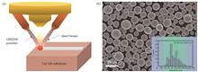
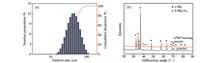
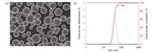
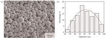
ObjectiveLaser powder bed fusion (LPBF) is an advanced manufacturing technology that involves the layer-by-layer deposition of metal powder, followed by rapid laser fusion. Unlike traditional methods for metal part fabrication, LPBF which does not require molds or tools can achieve near-net shaping of complex metal part, offering significant advantages. However, commercial LPBF systems generally use low-power (≤500 W), single-mode fiber lasers with Gaussian energy distribution. To fully melt the metal powder layer, key process parameters such as laser scanning speed, spacing, and layer thickness are constrained, resulting in low forming efficiency (1.8?16.2 cm3/h). This limitation hinders the use of LPBF in large-scale manufacturing. To address this, researchers have developed high-power LPBF (HP-LPBF) using lasers with ≥1 kW power. While studies have explored the formation of GH4169 alloys with HP-LPBF, most have used laser powers under 2 kW. Therefore, further investigation is needed to understand the densification behavior, microstructure, and mechanical properties of GH4169 alloys formed with laser powers exceeding 2 kW.MethodsThe HP-SLM320 laser additive manufacturing equipment, used as the HP-LPBF test platform, was developed in-house by our research team. The device was equipped with a multimode fiber laser that had a maximum output power of 4 kW and a near flat-top mode energy distribution. Metallurgical defects in the GH4169 alloys were observed using an optical microscope (OM). Phase composition was analyzed with a X-ray diffractometer (XRD). A scanning electron microscope (SEM) equipped with an electron backscattering diffractometer (EBSD) and an electron probe microanalyzer (EPMA) was used to characterize the microstructure, grain orientation, and composition distribution. Vickers hardness of the vertical section of the specimen was measured using a microhardness tester under a 500 g load and 15 s indentation time. Room temperature tensile tests were conducted on a high-precision electronic universal testing machine at a constant drawing rate of 2 mm/min.Results and DiscussionsIn this study, a high-power, near-flat-top laser beam is used for the HP-LPBF of a GH4169 nickel-based superalloy. The metallurgical defects, microstructure, and mechanical properties of the as-formed HP-LPBF samples are studied. When the laser volumetric energy density is less than 65 J/mm3, unfused defects are observed in the specimens, as shown in Figs. 5(a1)?(c1). However, when the laser volumetric energy density exceeds 65 J/mm3, these defects disappear, and the specimen density exceeds 99.80%. Within the experimental range of this study, the samples prepared with different laser volumetric energy densities exhibit few pores, as shown in Figs. 5 (d1)?(f1). The microstructures of the HP-LPBF samples consist of columnar dendrites and cellular dendrites. Laves phases, which are harmful, are distributed along the dendrite boundaries, similar to what is observed with conventional LPBF technology. However, the primary dendrite arm spacing (PDAS, 1.8 μm) in HP-LPBF specimens is larger than that seen with conventional LPBF (0.5?1.0 μm). Based on the relationship between PDAS and the cooling rate of the molten pool, the average cooling rate in HP-LPBF (9.8×10⁴ K/s) is only 2.0%?16.9% of that (5.8×10⁵?4.8×10⁶ K/s) in conventional LPBF . The average grain size (331 μm) in the HP-LPBF specimen is an order of magnitude larger than that (8.6?32.0 μm) produced by conventional LPBF, as shown in Fig. 9. This is due to the slower cooling rate in HP-LPBF. Additionally, the HP-LPBF specimen exhibits stronger preferred orientation characteristics compared to those produced by conventional LPBF, as shown in Fig. 10, which is attributed to the more uniform temperature gradient achieved with the near-flat-top laser beam.With a density exceeding 99.80%, the forming efficiency (118.8?166.3 cm3/h) of HP-LPBF specimens is more than 7 times that (1.8?16.2 cm3/h) of conventional LPBF technology. The elongation (34%) of a typical HP-LPBF specimen is comparable to the higher range (10%?40%) achieved with conventional LPBF. However, the ultimate tensile strength (895 MPa) falls within the middle to lower range of conventional LPBF results (845?1287 MPa), as shown in Fig. 13. The relatively coarse dendritic structure and relatively slow molten pool cooling rate are the main factors contributing to the elongation being on par with the higher levels observed in conventional LPBF. Meanwhile, the relatively larger solidified grains, coarse dendritic structure, and lower average geometrically necessary dislocation (GND) density are the primary reasons for the ultimate tensile strength aligning with the lower range of conventional LPBF results.ConclusionsSamples with densities exceeding 99.80% can be obtained by adjusting the laser volumetric energy density to ≥65 J/mm3. The as-formed HP-LPBF sample exhibits a dendritic microstructure with a PDAS of 1.8 μm, which is larger than that of the GH4169 superalloy formed using conventional LPBF with a low-power Gaussian laser beam. The Laves phase volume fraction (9.5%) in the HP-LPBF sample is comparable to that obtained with conventional LPBF. The sample also shows a cubic crystallographic texture with a strong “<001> is parallel to the building direction” orientation, stronger than that observed in conventional LPBF. The average equivalent grain size (331 μm) is an order of magnitude larger than in conventional LPBF. The ultimate tensile strength (895 MPa) of the HP-LPBF sample is within the middle to lower range of conventional LPBF results, while its elongation (34%) is on par with the higher range. Additionally, the forming efficiency (118.8?166.3 cm3/h) is more than 7 times that of conventional LPBF, given a density above 99.80%.
Jan. 20, 2025Vol. 52 Issue 4 0402302 (2025)
Feiyang Li, Gaohang Li, Baopeng Zhang, and Haihong Zhu
ObjectiveLaser powder bed fusion (LPBF) technology can shape metal components into almost any complex shape. Casting is the most commonly used method for fabricating magnesium (Mg) alloy components. However, because of the high vapor pressure and susceptibility of Mg to reacting with air, cast Mg alloys often exhibit defects and relatively poor mechanical properties. Mg alloys manufactured using methods such as forging, rolling, and extrusion are deformed to improve performance; however, forming complex magnesium alloy components is difficult. Although traditional manufacturing methods have laid the foundation for improving Mg alloy properties and their applications, these alloys struggle to meet the demands of complex components in fields such as aerospace, biomedicine, and electronic communication. The application prospects are widened by combining the characteristics of Mg alloys such as high specific strength, high specific stiffness, good electromagnetic shielding performance, and extremely low weight. Currently, the density of Mg alloys formed by LPBF is generally low, and the mechanisms underlying defect formation and microstructural evolution remain unclear. In this study, the densification behavior, defect formation mechanism, and microstructure of LPBF-formed AZ91D magnesium alloy are investigated under different process parameters, and high-quality samples of AZ91D magnesium alloys are formed using LPBF technology.MethodsAZ91D magnesium alloy specimens were formed using LPBF equipment with a fiber laser wavelength of 1064 nm and a maximum laser power of 500 W. During processing, the laser spot size was adjusted to 80 μm, and two preheating temperatures of 25 ℃ and 200 ℃ were applied. Square specimens measuring 10 mm×10 mm×10 mm were formed on cast AZ91D magnesium alloy substrates. An optical microscope (OM) was used to capture metallographic images, and ImagePro Plus software was used for defect shape and type statistics analysis. A scanning electron microscope (SEM) was employed to analyze the internal morphology of the defects and the microstructure of the formed specimens. The elemental composition of the specimens was characterized using a SEM with energy-dispersive X-ray spectroscope (EDS). An universal material testing machine was used to conduct room-temperature static tensile tests on relevant specimens.Results and DiscussionsUnder a preheating condition of 200 ℃, the forming interval of AZ91D magnesium alloy can be distinctly divided into porosity, transition, dense forming, and unmelted zones. In the dense forming area, high-density (99.9%) AZ91D specimens without voids or lack-of-fusion defects were successfully formed. Under the processing conditions used in this study, the forming density was sensitive to hatch space such that when the hatch space increased to 0.08 mm, the overall forming density decreased significantly. In Fig. 5, when the hatch space is 0.08 mm, the range of input energy density (150 J/mm3≤ρE≤280 J/mm3) in the dense forming zone decreases significantly compared with that (120 J/mm3≤ρE≤380 J/mm3) when the hatch space is 0.06 mm, and the unmelted range significantly increases. An increase in hatch space leads to more inter-track lack-of-fusion defects, resulting in a larger unmelted zone. Under the preheating condition of 25 ℃, several specimens cannot be formed simultaneously, and the formation is unstable. During the formation of Mg alloys, evaporation of elements leads to a large number of porosity defect variations formed according to the Stokes law in Equation (4). At a high laser power and low scanning speed, keyhole and vapor pores appear simultaneously. In samples with a hatch space of 0.08 mm, unmelted powder is observed in the unmelted zone, presenting a typical inter-track lack-of-fusion shape. At a high laser power and low scanning speed, a large number of elements evaporate during the forming process of magnesium alloys, which removes heat and shields the laser. Under a preheating condition of 200 ℃, the evaporation of elements is the dominant factor affecting the grain size of specimens formed using different parameters. Under the same processing parameters, specimens formed under a preheating temperature of 25 ℃ exhibit finer grains than those formed at 200 ℃, with the cooling rate being the dominant factor. The microstructures of the formed AZ91D magnesium alloy specimens are determined based on the cooling rate and evaporation of the elements. However, under a preheating temperature of 25 ℃, a higher temperature gradient predisposes the specimens to cracking, interfering with their formation.ConclusionsHigh-density specimens (99.9%) were successfully formed without porosity or lack-of-fusion defects under a preheating condition of 200 ℃, with a laser power of 200 W, scanning speeds ranging from 300?400 mm/s, and a hatch space of 0.06 mm. With an increase in hatch space to 0.08 mm, inter-track lack-of-fusion defects increased, leading to a decrease in overall forming density and a reduction in the forming window, as the dense forming input energy density range changed from 120 J/mm3≤ρE≤380 J/mm3 to 150 J/mm3≤ρE≤280 J/mm3. The specimens were characterized by keyholes and evaporative pores with different morphologies on the inner surfaces of their walls. The evolution of the specimen microstructures was jointly determined by the cooling rate and element evaporation. At the same preheating temperature, specimens with severe element evaporation usually had finer grains. For the same processing parameters, the specimens with lower preheating temperatures had finer grains because of the higher cooling rate. With the dense forming parameters, the ultimate tensile strength (UTS) reached (322.04±6.72) MPa, and the yield strength reached (258.07±4.72) MPa, and the mechanical properties far exceeded those of cast Mg alloys, reaching forging standards.
Jan. 20, 2025Vol. 52 Issue 4 0402303 (2025)
Yujing Chi, Denghao Yi, Jianmin Li, Shuo Geng, Zenghao Miao, and Dongyun Zhang
ObjectiveRecent studies have shown that Ti6Al7Nb alloy, which is prepared to improve biocompatibility, exhibits mechanical properties comparable to Ti6Al4V alloy while demonstrating superior corrosion resistance, ductility, biological compatibility, and bioactivity. It is considered an ideal biomaterial for medical titanium alloys. However, for components with complex geometries or medical implants, traditional manufacturing methods require significant time and labor costs. To overcome these manufacturing barriers, the use of laser powder bed fusion (LPBF) technology for producing metal components and implants has emerged as a solution. However, determining the optimal processing window for LPBF is challenging owing to the multiple parameters affecting the quality of the products. Additionally, during the LPBF process, excessive cooling rates can lead to rapid solidification of the melt pool, resulting in the formation of fine grains and supersaturation. In the case of LPBF-formed Ti6Al7Nb alloy, the presence of ultrafine needle-like α' martensitic structures leads to a high yield strength but low ductility because of the formation of α' martensite. While the strength of the material is guaranteed, there may be shortcomings in plasticity. Therefore, post-processing heat treatment of the formed components is essential. This study aims to adjust the key parameters of LPBF to obtain the optimal processing window and conduct heat treatment on specimens formed using the optimal processing parameters. The influence of the main parameters of LPBF on the quality of the formed products is investigated, and the effect of different treatment methods on the microstructure and mechanical properties of the specimens is analyzed.MethodsIn this study, Ti6Al7Nb powder with a particle size distribution of 25?65 μm was used to prepare alloys with different forming parameters. Five sets of parameters for laser power and four sets each for hatch spacing and scanning speed were established, resulting in a total of 80 experiments conducted using an orthogonal experimental design. The optimal processing parameters were determined through a phase analysis of the formed alloys (Fig. 3 and Table 3). Subsequently, the specimens formed using the optimal parameters were subjected to heat treatment using the three solution treatment temperatures shown in Table 2. The microstructure variations were studied via optical microscopy, scanning electron microscopy, and X-ray diffraction analysis. Tensile tests were performed to obtain the mechanical properties of the specimens subjected to different treatments, and fractographic analysis was also conducted. The optimal heat treatment regimen was derived through these methods.Results and DiscussionsIn the LPBF-formed alloy specimens, columnar β-phase crystals grow along the formation direction, whereas needle-like α' martensite phases precipitate at a 45° angle to the formation direction, as illustrated in Fig. 8. The material exhibits high strength but low ductility, with the tensile fracture surface mainly characterized by shallow dimples and transgranular cracking features [Figs. 13(a)?(d)]. This behavior is attributed to the significant differences in thermal gradient present in the LPBF process. Under 850 ℃ solid solution treatment, the strength of the specimens decreases, whereas the ductility significantly improves, surpassing ASTM standards. The tensile fracture surface exhibits pronounced necking, primarily due to the decomposition of the needle-like α' phase into α+β phases during high-temperature heat treatment, although the decomposition is not complete. In contrast, 950 ℃ solution treatment results in the dispersion and pronounced orientation of needle-like α' martensitic phases and an increase in the precipitation of β phases within the grain interiors, with secondary α phases isolated by the organization of the β phase. This structural arrangement leads to lower strength and ductility in the S2 specimen compared to the S1 specimen, albeit with a slight increase in surface hardness. Heat treatment at 1050 ℃ within the α+β dual-phase region results in a typical Widmanst?tten microstructure. The β phase undergoes β→α+α' transformation at high temperatures, leading to a significant increase in material hardness and strength, but with reduced ductility compared to the previous two heat treatments (Figs. 11 and 12). The tensile fracture surfaces display extensive tearing ridges and river-like patterns. After aging treatment, the microstructure of the solid solution treated specimens undergoes minimal change, but both the strength and ductility exhibit improvement, particularly in terms of yield strength. The enhanced strength is attributed to the further decomposition of the metastable α' phase, the increased content of dispersed α+β phases, and the strengthening effects of fine grains, as corroborated by Fig.s 6 and 7. An integrated analysis of the experimental heat treatment regimens indicates that a combination of the 850 ℃×0.5 h / air cooling (solid solution treatment) and 550 ℃×0.5 h /air cooling (aging treatment) can achieve an optimal strength?ductility balance for LPBF-formed Ti6Al7Nb alloy specimens.ConclusionsThe Ti6Al7Nb alloy was successfully shaped using LPBF technology, and by controlling the main forming parameters, the optimal alloy forming quality was achieved. The microstructure and mechanical properties of the alloy were adjusted to meet medical standards through solid solution and aging treatment. The research results indicate that the best formation quality of the specimens is achieved under a laser power of 300 W, a hatch spacing of 0.12 mm, and a scanning speed of 1150 mm/s. The comprehensive results of all heat treatment strategies suggest that a solid solution treatment temperature selected within the mid-section of the α+β dual-phase region is most suitable. At this temperature, the needle-like α' martensitic phase decomposes into the α+β phase and distributes uniformly throughout the alloy. With an increase in the solid solution treatment temperature, although the complete decomposition of the needle-like α' martensitic phase is more pronounced, higher undercooling can lead to the transformation of the β phase into the α and α' phases. Following the aging treatment, the overall strength of the alloy is enhanced owing to the recrystallization and decomposition of the α' phase.
Jan. 07, 2025Vol. 52 Issue 4 0402304 (2025)
Li Zhao, Tongshuai Zhao, Ju Zhou, Changjun Qiu, and Hongmei Zhu
ObjectiveThe laser fabrication of Ti6Al4V (TC4) alloy in an atmospheric environment is susceptible to nitrogen (N) and oxygen (O); consequently, defects such as cracks can occur because of the induced embrittled nitride and oxide phases. Therefore, the industrial application of LDED (laser direct energy deposition) -treated titanium alloy components has been severely hindered by the limited space and high cost in the closed environment. In this study, a novel nozzle with a protective hood was designed for the laser additive manufacturing of TC4 alloys to alleviate the adverse effects of N and O in an atmospheric environment. The microstructures and mechanical properties of the as-deposited TC4 specimens with and without hoods (named TC4-Y and TC4-N, respectively) were evaluated. A functional prototype of the multiflow-path nozzle was developed using computational fluid dynamics (CFD) simulations with species transport and the k?ε gas model. This study significantly benefits the laser fabrication of low-cost and high-performance Ti components in various industrial fields.MethodsGas-atomized TC4 powder with an average size range of 75 μm was employed to fabricate LDED-treated specimens using an FL-1500 1.5 kW fiber laser. The processing parameters were set as follows: laser power, 500 W; scanning speed, 600 mm/min; and powder delivery rate, 4.85 g/min. Both the central and side gases are high-purity Ar (99.99%) and were flowed at a rate of 10 L/min. CFD simulations of the gas flow adjacent to the substrate surface, which was located 2.5 mm away from the nozzle of the air hood, were performed to evaluate the effectiveness of the hood. To investigate the microstructural evolution of the LDED-treated TC4 alloy, the samples were polished and then etched with Kroll's reagent. The phase compositions were determined using a Miniflex600 X-ray diffractometer (XRD). The microstructure was investigated using a MERLIN scanning electron microscope (SEM) operated at an accelerating voltage of 20 kV and a JEOL-2100 transmission electron microscope (TEM) operated at 200 kV. The mechanical properties of the samples were evaluated using an HVS-1000 microhardness tester and a PWS-E100 universal testing machine.Results and DiscussionsThe simulation results indicate that the facet average mass fractions of N2 and O2 reduced significantly from 1.628×10⁻³ to 2×10⁻⁴ and from 4.37×10⁻⁴ to 5.4×10⁻⁵, respectively (Fig. 3), which agree well with the experimental results. The TC4-N specimen is composed of needle-like α′ martensite, Widmanst?tten α-laths, β-phase, and nitrides (Figs. 6?8). By applying the protective hood, the TC4-Y specimen exhibits a decrease in α/α′ martensite content, an increase in the β-phase fraction, and the precipitation of Ti3AlC2 phase (Figs. 6?8). The average microhardness values of the TC4-N and TC4-Y specimens are 410 HVand 365 HV(Fig. 4), respectively. The higher microhardness of the TC4-N specimen is primarily due to the in-situ formation of hard nitride TiN (2900 HV) during LDED. In comparison, the TC4-Y samples indicate a slightly lower value (365 HV) that is equivalent to those fabricated in a chamber filled with an inert gas (316?369 HV). Under the protection of the hood, the TC4-Y samples exhibit an average UTS of 1037 MPa, a YS of 952 MPa, and an EL of 10.2% (Fig. 5), which are comparable to those of TC4 counterparts achieved in a closed environment. This demonstrates the effectiveness and feasibility of the protective hood.ConclusionsThe newly designed protective hood effectively eliminates the adverse effects of N and O. A CFD simulation was conducted, which demonstrated that the hood successfully prevented contamination by impurities, including N and O. The N and O mass fraction adjacent to the sample surface decreased by 1.38×10⁻³ and 5.7×10⁻⁴, respectively. The TC4-N specimen is composed of needle-like α′ martensite, Widmanstatten α-laths, β-phase, and nitrides. The TC4-Y specimen primarily comprises coarsened α′ martensite, Widmanstatten α-laths, Ti3AlC2 nanoprecipitates, and β-phase. Under the synergistic effect of refinement strengthening, solid-solution strengthening, and second-phase strengthening, the TC4-N specimen exhibits higher levels of strength (UTS of 1249 MPa, YS of 1028 MPa) and microhardness (410 HV). By contrast, an exceptional combination of high strength (UTS of 1037 MPa, YS of 952 MPa) and high ductility (10.2%) is achieved owing to the presence of α/α′ with a low aspect ratio, a high fraction of β-phase, and Ti3AlC2 nanoprecipitates in the TC4-Y specimen. This study reports a simple yet effective approach for producing LDEDed TC4 alloys with outstanding mechanical properties in an atmosphere, which significantly benefits industrial applications.
Jan. 07, 2025Vol. 52 Issue 4 0402305 (2025)
Yiwei He, Jie Chen, Qin Yang, Shuke Huang, Zheng Xiang, Tianhao Zhang, and Xianfeng Shen
ObjectiveAs a low-expansion alloy, Invar 36 alloy is commonly used in scenarios involving significant environmental temperature changes and high-precision requirements. However, its high density and machining difficulty limit its application in the aerospace field. The use of the laser powder bed fusion (LPBF) technology to fabricate lattice-filled Invar 36 alloy structures can effectively address these issues. Existing studies pertaining to the mechanical properties of lattice-filled structures focus on energy-absorption characteristics under compressive loading. Meanwhile, studies regarding the optimization of the structural stiffness of lattice-filled structures under compressive loading are scarce. Therefore, lightweight and high-stiffness lattice-filled structures must be urgently developed. Additionally, studies regarding lattice-filled structures based on Invar 36 alloy have not yet been reported. This study uses LPBF technology to fabricate Invar 36 alloy lattice-filled structures with various structural parameters, which results in good forming performance. Furthermore, this study provides valuable insights into the lightweight design of Invar 36 alloy components.MethodsInvar 36 alloy lattice-filled structures with different structural parameters were fabricated via LPBF. The strut diameters are 0.8, 1.0, and 1.2 mm; the cell dimensions are 4, 6, and 8 mm; and the thickness of the skin is 1 mm. Optimized fabricating parameters were used: laser power, 280 W; scanning spacing, 0.12 mm; scanning speed, 1200 mm/s; powder thickness, 0.04 mm; and interlayer turn angle, 67°. A strip-scanning strategy featuring a strip width of 7 mm and a strip overlap of 0.08 mm was adopted. After fabrication, the samples were heat treated by increasing the temperature to 750 ℃ and maintaining it for 1.5 h, followed by cooling down to room temperature under argon atmosphere. The samples were sandblasted and cleaned ultrasonically to remove adhesive powder from the sample surfaces. Quasi-static compression tests and finite-element analyses were performed on the lattice-filled structures to investigate and analyze the compression curves, deformation modes, and stress distributions.Results and DiscussionsThe compression stress?strain curves of the lattice-filled structures with different structural parameters are shown in Fig. 5. For the lattice-filled structures with cell dimensions of 8 mm and 6 mm, the curves can be classified into four characteristic regions: the elastic region; the force-drop region featuring a significant decrease in compressive stress; the plateau region; and the densification region. By contrast, the lattice-filled structure with cell dimensions of 4 mm neither exhibits a peak nor a compressive-stress-decrease region, which can be classified into three regions. This difference is primarily related to the deformation mode of the lattice-filled structures. When the strut diameter and number of lattice layers are small, the compressive deformations of the lattice-filled structures are primarily determined by the behavior of the lateral skin, which results in deformation characterized by skin wrinkling and shear-type global buckling (Fig. 7). Under these deformation modes, the compression curve is reflected by the abrupt stress after the peak strength. The compression performance of the lattice-filled structure is significantly enhanced when the strut diameter and number of lattice layers are further increased. Under this condition, the stronger constraining effect between the skin and lattice core restricts the local buckling of the skin (Fig. 8). However, a larger strut diameter can facilitate load transfer (Fig. 10). The stress is uniformly distributed inside the lattice core, and the local buckling deformation does not cause the compressive stress to decrease abruptly.The Gibson?Ashby model was used to predict the performance of the Invar 36 alloy lattice-filled structures. The higher the relative density, the better is the structural compression (Fig. 11). However, for a specified mass, if the cell dimensions increases, then the strut diameter decreases. Therefore, the coupling effects of the structural parameters must be considered when designing lightweight materials.ConclusionsThe effects of structural parameters on the compression performance and deformation behavior of Invar 36 alloy lattice-filled structures were investigated via quasi-static compression tests and finite-element analyses. First, the compressive elastic modulus, plateau stress, and energy-absorbing properties of the lattice-filled structures fabricated via LPBF improve significantly as the cell dimensions decreases and the strut diameter increases. Second, the lattice-filled structures with different structural parameters exhibit three deformation modes: skin wrinkling, shear-type global buckling, and local skin buckling. Their deformation behaviors are coupled with skin tensile-dominated and lattice-filled core bending-dominated deformations. Third, the deformation behaviors obtained from finite-element analysis are consistent with the compression test results. Moreover, different structural parameters significantly affect the load transfer and stress distribution, which ultimately results in lattice-filled structures exhibiting different deformation modes. Finally, the coupling effect of the structural parameters should be fully considered when using lattice-filled structures as lightweight Invar 36 alloy members. For a specified mass, a cell dimension of 6 mm and a strut diameter of 1 mm are the better parameters for optimizing the structural stiffness, which can yield 1.75 GPa·g-1·cm-3 for the latter.
Jan. 20, 2025Vol. 52 Issue 4 0402306 (2025)
Feng Wang, Xingxing Hao, Xiaonan Wang, Wengang Chen, and Xiang Li
ObjectiveTitanium alloys are widely used in aerospace, automotive manufacturing, and marine engineering because of their high strength, low density, and excellent corrosion resistance. Laser welding, owing to its high energy density, high precision, and small heat-affected zone, provides robust support for connecting critical titanium-alloy components in industrial applications. However, during the laser welding of titanium alloys, the involved high-density Gaussian laser energy can generate defects easily, e.g., pores in the weld seam, thus adversely affecting the performance of the welded joint. In laser manufacturing, the emergence of novel lasers offers new possibilities for suppressing such defects. Fiber-diode laser hybrid welding enables the efficient and high-quality welding of highly reflective materials and has garnered widespread attention from academia and industry. Nevertheless, the effects of diode laser power and welding speed on titanium-alloy welding properties in fiber-diode laser hybrid welding remain unclear, thereby hindering theoretical guidance and process optimization for industrial applications. Therefore, this study investigates the effects of diode laser power and welding speed on the formation, microstructure, and mechanical properties of joints realized via fiber-diode laser hybrid welding to determine the optimal process window.MethodsIn this study, the effects of diode laser power (1.0, 1.5, and 3.0 kW) and welding speed (30, 60, and 120 mm/s) on the formation, microstructure, and mechanical properties of 4 mm thick TC4 titanium-alloy joints welded via fiber-diode laser hybrid welding were investigated. Welding experiments were performed using a fiber laser with a wavelength of 1080 nm, a core diameter of 34 μm, and a spot diameter of 45 μm, and a diode laser with a wavelength of 915 nm, a core diameter of 600 μm, and a spot diameter of 1.2 mm. High-purity (volume fraction of 99.99%) Ar gas flowed at a rate of 30 L/min was used as the shielding gas during welding. The experimental parameters are listed in Table 2.Results and DiscussionsFigure 2 shows the macrosectional formations of the welds at different diode laser powers. As the diode laser power increases, the weld morphology transforms from a “Y” shape to a “goblet” shape, with the upper weld width increasing by approximately 60% (from 1.8 mm to 2.9 mm). Simultaneously, the width of the heat-affected zone increases, whereas that of the lower weld remains relatively unchanged. This indicates that the diode laser energy preferentially conducts heat laterally, thereby modulating the transient thermal convection within the molten pool. As depicted in Fig. 3, the grains in the hybrid-laser action zone are much coarser compared with those in the single-laser action zone, which is attributable to the higher heat input. In terms of the mechanical properties, as shown in Fig. 4, the tensile strength decreases with increasing diode laser power (from 918 MPa to 907 MPa), whereas the elongation after fracture remains relatively constant (average of approximately 6%), with fracture occurring in the weld seam. The fracture morphology shows an increase in the number of keyhole-type pores in the weld as the diode laser power increases. This suggests that excessive diode laser power destabilizes the keyhole, thus deteriorating the mechanical properties of the joint.Figure 6 shows the macrosectional formations of the welds at different welding speeds. As the welding speed increases, the weld formation changes from an “X” shape to a “Y” shape, and the width of the heat-affected zone decreases due to reduced heat input. As shown in Fig. 7, the grain size decreases with increasing welding speed (from 2.99 μm to 2.87 μm). This reduction in grain size causes an increase in the number of grains and thus an increase in the proportion of high-angle grain boundaries (from 80.5% to 84.0%). In terms of the mechanical properties, as illustrated in Fig. 10, both the tensile strength and elongation after the fracture of the joints first increase and then decrease with increasing welding speed, with the maximum tensile strength reaching 927 MPa and the elongation being 9%. Fractures occur in the base material. As shown in Fig. 11, an increase in the welding speed reduces the heat input, refines the grain size, and enhances the mechanical properties of the joint. However, when the welding speed further increases to 120 mm/s, the solidification rate of the molten pool decreases significantly, thus preventing bubbles from escaping and deteriorating the mechanical properties of the joint.ConclusionsDuring laser hybrid welding, the energy of the diode laser tends to propagate laterally, which is conducive to stabilizing the keyhole and reducing the porosity in the weld seam. However, when the power of the diode laser exceeds a certain range, an increase in the laser power can paradoxically reduce the stability of the optically induced keyhole, thus deteriorating the mechanical properties of the joint. As the welding speed increases, the heat input decreases, thus refining the grain size considerably and increasing the number of high-angle grain boundaries. Nevertheless, the values of the mechanical properties first increase and then decrease as the welding speed increases. This is because, when the welding speed exceeds a certain threshold, the solidification time of the molten pool shortens, thus preventing bubbles from escaping in time. Consequently, the porosity of the weld seam increases and the mechanical properties of the joint deteriorates.
Jan. 20, 2025Vol. 52 Issue 4 0402101 (2025)
Longzhi Zhao, Xiuping Hu, and Mingjuan Zhao
ObjectiveLaser-powder-filling welding is an important method for joining aluminum matrix composites owing to its high processing speed, minimal thermal impact on the matrix, and excellent controllability. However, in practical applications of laser-powder-filling welding, the intense Marangoni convection in the aluminum-alloy molten pool results in undesired weld morphologies such as humps and surface instability, thus deteriorating the mechanical properties and stability of the joints. Magnetic-assistance technology, owing to its advantages of high flexibility, high efficiency, low cost, and non-contact nature, has become a potentially effective method to control the flow of molten metals, improve welding controllability, and enhance product quality. Recent studies that improve welding quality using steady magnetic fields primarily focus on the effect of magnetic fields on arc welding or deep-penetration laser welding. Meanwhile, most studies examine the effects of transverse steady magnetic fields on aluminum-alloy welding, whereas few studies investigate the powder or wire-filling welding of aluminum matrix composites. Thus, the effect of reinforcements on the physical properties of the base metal is yet to be elucidated. Furthermore, owing to the difficulty in capturing the flow behavior of molten pools and the complex effect of external magnetic fields in the molten pool, the mechanisms of magnetic-field distributions and the Lorentz force in the molten-pool flow field under magnetic-field assistance remain ambiguous. Therefore, welding simulation studies should be conducted on magnetic-field-assisted aluminum matrix composites.MethodsA SiCp/2009Al composite matrix and AlSi12 filler powder are used in this study, with the magnetic field directed vertically perpendicular to the bottom surface of the matrix, and the magnetic-field intensity reaching 1.0 T. First, a three-dimensional transient numerical model is established using the COMSOL Multiphysics simulation software, which considers the variations in the material physical properties and couples fluid heat transfer with the magnetic field. Meanwhile, thermal buoyancy, surface tension, the Lorentz force, and other forces are applied to the molten pool. Subsequently, the Lorentz-force distribution in the steady magnetic field, as well as the fluid flow, heat transfer, and cooling behaviors in the central region of the molten pool are investigated. Finally, the profile morphology of the molten pool is verified through experimental observations.Results and DiscussionsThe functional relationship between the longitudinal section height of the weld and the magnetic flux density was obtained via fitting, which provides clear understanding regarding the decay law of the magnetic field in space. Under the action of the longitudinal magnetic field, the molten pool is primarily affected by transverse electromagnetic forces, which can generate a shear effect on the interface (Fig. 4). As the steady magnetic flux density increases, the Marangoni convective motion in the molten pool weakens gradually, whereas the vortex rings on the front and rear sides of the molten-pool center diminish gradually until they disappear, thus decreasing the convective heat-transfer intensity in the molten pool, reducing the temperature gradients, and resulting in a more uniform distribution of the laser heat input in the longitudinal direction (Figs. 5, 6, and 7). Additionally, the cooling rate in the molten pool decreases significantly with the magnetic flux density, and the cooling and heat dissipation mechanisms of the molten material primarily involve thermal conduction and radiative heat loss (Fig. 8). At any position of the molten pool in the steady magnetic field, the induced Lorentz force and convective flow are in opposite directions, thus compensating for the Marangoni shear force and yielding an electromagnetic braking effect on the molten pool, which is the primary contributor to the weakening of convective heat transfer in the molten pool (Figs. 9 and 10). Meanwhile, the simulated molten-pool contour undulation and the mushy zone decrease. Additionally, a uniform microstructure distribution, good formability, and welding joints with reduced porosity are achieved from the welding processes (Fig. 11). The simulation results of temperature-field distribution and geometry agree well with the experimental results.ConclusionsIn the laser-powder-filling welding of SiCp/2009Al composites under the assistance of a steady magnetic field, the magnetic field alters the energy distribution in the molten pool, which minimizes the thermal gradients and consequently reduces the heat-affected zone of the welding joint, thus resulting in a more uniform microstructure distribution. Meanwhile, the steady magnetic field reduces the cooling rate of the molten pool, favors an extended period for allowing bubbles to escape the solidification interface, and decreases the number of pores in the welded joint. Increasing the magnetic flux density will further weaken the Marangoni convection in the molten pool and reduce the heat-transfer intensity of convection in the molten pool. The convective vortices gradually diminish until they disappear, thus resulting in a more stable flow in the molten pool. Furthermore, the transverse Lorentz force generated by the longitudinal magnetic field exerts a significant braking effect on the lateral fluid flow in the molten pool, thus reducing the cross-sectional size of the molten pool. Solutes are primarily transported toward the bottom of the molten pool under the action of natural convection, thereby improving weld formation.
Jan. 15, 2025Vol. 52 Issue 4 0402102 (2025)
Zhuo Chen, Xingzhi Xiao, Wenhe Liao, Tingting Liu, Shilin Wang, and Gang Li
Objective3D printing of structural electronics can realize the synchronous forming of dielectric substrates and conductive circuits, and it has a broad application prospect in the manufacturing of, for example, flexible wearable and smart skins. The morphology and electrical properties of conductive circuits after sintering directly influence the in-service performance of structural electronic products. The conventional thermal sintering of conductive silver paste circuits usually requires a long period of high-temperature heating, which has a significant impact on the polymer substrate for conductive circuits and reduces their printing accuracy. Although the emerging electric sintering/laser sintering can reduce the thermal impact on the polymer substrate material, the sintered circuits still suffer from internal pores, poor structural shape consistency, and high resistivity. In this paper, we propose a “hot airflow + laser” composite sintering method, which results in sintered circuits with high densities, high consistency, and low resistivity. We hope that this composite sintering method will contribute to the fabrication of higher precision, lower resistivity conductive circuits and help to understand the relationship between sintering temperature and resistivity of conductive silver paste circuits.MethodsThe existing laser sintered conductive silver paste lines suffer from internal pores, circuit expansion, resistivity, and other issues. This study proposes a composite sintering system. A comparison test with single laser sintering is carried out. The surface morphology and internal defects of the sintered circuits are detected. Analyses of conductivity of the silver paste lines, their expansion behavior, and the elemental changes are conducted, showing a clear mechanism of inhibition of the pore defects. A test of the resistance of the circuit is performed to analyze the pattern of change of the resistance value. On this basis, the correlation among pore defects, circuit expansion, and electrical properties is established. This study provides a new method for high density, low resistivity forming of conductive silver paste lines.Results and DiscussionsIn the present study, a “hot airflow + laser” composite sintering process of conductive silver paste is proposed, and a sintering system with hot airflow pre-sintering function is built (Fig. 4). Comparison experiments of laser/composite sintering with variable parameters are carried out (Table 3). The results show that, compared with the laser sintered circuits, the proposed composite sintering leads to lower electrical resistivity (Fig. 6), smaller cross-sectional area (Fig. 9), lower electrical resistance value (Fig. 15), and higher consistency (Fig. 8). The reason for the inhibition of pore defects using the composite sintering process is identified. The hot gas flow promotes the thermal decomposition process of organic substances in the silver paste and volatilizes them from the surface of the nondense silver paste. This avoids the gas volatilization from the dense surface of the laser sintered surface, thus reducing the generation of internal pore defects (Fig. 12). The composite sintering process promotes the reduction in resistance value due to the elevated silver content on the surface of the circuits after hot gas flow sintering, the increase in thickness of the dense surface layer after laser sintering, the increase in the effective transmission area of electrons, and the improvement of the electron flow efficiency (Fig. 17). Finally, the study reveals that the hot airflow promotes the decomposition of organic matter within the silver paste (Table 4), and the laser accelerates the fusion of silver nanoparticles (Fig. 18).ConclusionsThis study proposes a “hot airflow + laser” composite sintering process of conductive silver paste, builds a sintering system with hot airflow pre-sintering function, and carries out a laser sintering and “hot airflow + laser” sintering comparative process test. The low-temperature pre-sintering of the circuit inhibits the internal pore defects, and the electrical properties of the circuit are improved. Based on the characteristics of the organic matter ladder of thermal reaction, it is revealed that the pre-sintering temperature promotes the removal of organic material. A correlation between the organic matter residue and the generation of pore defects is established. This study provides a theoretical basis for the high-precision, low-resistivity molding of conductive silver paste. The specific conclusions are as follows:1) The reduction in resistivity of the conductive silver paste circuit after the “hot airflow + laser” composite sintering, compared with that obtained with laser sintering, is significant. A maximum resistivity reduction of 67% is achieved.2) Hot airflow pre-sintering before laser sintering can promote the decomposition of organic solvents within the conductive silver paste. This avoids the violent reaction produced by laser sintering of organic substances, inhibits the generation of pore defects in the conductive silver paste lines, and reduces the expansion of the conductive silver paste circuits. Compared with that obtained with laser sintering, the circuit cross-sectional area is reduced by 50%?60%.3) “Hot airflow + laser” composite sintering improves the circuit surface layer density, increases the effective cross-section of the circuit current transmission, and reduces the circuit resistance value. Compared with that obtained with laser sintering, the circuit resistance value is reduced by 30%?45%.
Jan. 20, 2025Vol. 52 Issue 4 0402103 (2025)
Xiaojie Hao, Chenghong Duan, Xiangpeng Luo, Xiankun Cao, Hangcheng Xu, and Zongtao Zhu
ObjectiveMedium-thick aluminum alloys have a wide range of application prospects in railway transportation; therefore, studying the welding of medium-thick aluminum alloys is crucial. Laser-MIG hybrid welding (MIG, metal-inert gas) combines the advantages of laser heat source and arc heat source while compensating for their individual shortcomings, making it particularly suitable for welding medium-thick plates. To enhance welding efficiency, it is essential to analyze the single-layer, single-pass welding process. This study focuses on the microstructures and mechanical properties of laser MIG-welded joints of 6005A aluminum alloys with different groove dimensions.MethodsIn this study, a 10 mm thick 6005A aluminum alloy is welded using the laser-MIG hybrid welding technique in a single-layer, single-pass manner. Welding tests are conducted under a constant laser power, welding speed, and wire feeding speed of 5000 W, 16 m/min, and 8 mm/s, respectively, using different groove dimensions, including a root thickness of 5 mm with groove angles of 50°, 60°, and 70° and a groove angle of 60° with root thicknesses of 4 mm and 6 mm. The microstructures of the welded joints are analyzed using optical microscope (OM) and electron backscatter diffraction (EBSD). Tensile tests are performed on the specimens at a rate of 2 mm/min, and the tensile fracture morphology is observed using scanning electron microscope (SEM). The hardnesses of the welded joints are measured using a Vickers hardness tester. Finally, the weld temperature field is investigated using finite element analysis, and time?temperature profiles are extracted for specific locations.Results and DiscussionsA metallographic analysis reveals that successful weld connections are achieved for plates with different groove dimensions under constant processing conditions. Because of the similar heat input during welding, the microstructure of the welded joint exhibits the analogous performance. The grains in the center of the weld zone (WZ) are equiaxed dendrites, whereas those near the fusion zone are columnar dendrites, oriented perpendicular to a fusion line. The heat-affected zone (HAZ) shows randomly distributed, large black precipitate phases, which are significantly larger than the uniformly distributed point-like precipitate phases in the base metal (BM). The grain diameter in the WZ is about 140 μm, while the grain diameters in the HAZ and BM are 73 μm and 76 μm, respectively. The grain diameter in the WZ is much larger than those in the HAZ and BM, whereas the grain diameter in the HAZ is similar to that in the BM (Fig. 7). The tensile strengths of the specimens with different groove dimensions are 75%?79% of that of the BM, indicating that the welded joints have good bond strengths (Table 4). Because all the tensile fractures are in the HAZ, the HAZ is the weakest region (Fig. 8). This is mainly because of the severe softening behavior that occurs in the HAZ during welding. Fracture morphologies indicate that the fracture type is ductile (Fig. 9). The hardnesses of the welded joint in the HAZ and WZ are significantly lower than that of the BM, with the minimum hardness observed in the HAZ (Fig. 10). This reduction is mainly due to the transformation of a strengthening β phase into a β '' phase during thermal cycling. A finite element analysis shows that the region with a peak temperature of 480 °C in the HAZ corresponds to the location of minimum hardness (Fig. 13).ConclusionsThe paper studies the single-layer, single-pass laser-MIG hybrid welding process of a 6005A aluminum alloy with a thickness of 10 mm, and the relevant properties of the welded joints with different groove dimensions are analyzed. Plates with different groove dimensions are successfully joined at a laser power of 5000 W, wire feed rate of 16 m/min, and welding speed of 8 mm/s. The grains in the WZ are equiaxed at the center and columnar at the fusion line. The material in the WZ undergoes repetitive melting and solidification to form larger grains, whereas the grains in the HAZ and BM remain almost unchanged. The HAZ is the weakest region of the welded joints of the aluminum alloy 6005A. The tensile properties of specimens with different groove dimensions are similar, and their fracture characteristics are mainly ductile. Softening behavior occurs in all the welded joints, and the heat-affected zone exhibits minimum hardness. An analysis of the corresponding welding temperature field confirms that the region with a peak temperature of 480 °C is the softest region of the welded joints.
Jan. 20, 2025Vol. 52 Issue 4 0402104 (2025)
Cheng Xiong, Peng Pan, Shuangjian Chen, Wu Tao, Yanjun Wang, Zhe Lin, Zhengqiang Zhu, and Shanglu Yang
ObjectiveIn the field of electronic packaging, the preparation and application of traditional electronic packaging materials such as W/Cu and Mo/Cu are relatively mature. However, these materials have high density and low thermal conductivity, which cannot meet the packaging requirements of high-power portable electronic devices. Aluminum matrix composites have higher strength, wear resistance, and economy, which not only can overcome the shortcomings of traditional packaging materials but can also meet the application requirements of electronic packaging. In SiCp/Al composites, SiC particles react with the Al matrix to form needle-like brittle phase Al4C3 during high-temperature melting, which diminishes the welding performance of the joint and severely restricts the welding application of the material. Swing laser welding is expected to improve the microstructures and performances of SiCp/Al welded joints by improving the weld-forming morphology and inhibiting pore formation. Few studies have been conducted on the effects of the beam swing on the laser welding of SiCp/Al composites. Accordingly, in this study, the effects of beam swing mode, amplitude, and frequency on the laser welding of SiCp/Al composites were systematically analyzed. The effects of different laser swing modes and process parameters on the laser welding of SiCp/Al composites are revealed by controlling the variable method. The study on the welding microstructure and mechanical properties provides valuable experimental data for obtaining effective welding of SiCp/Al composites.MethodsThe test materials were a welding wire with a diameter of 1.2 mm and a SiCp/6005A composite material with dimensions of 60 mm×50 mm×4 mm. The effects of the different swing parameters on the welding properties of the SiC/Al composites were studied using the control-variable method (Table 2). Four modes of laser beam swing were used during welding: Linear, Circular, “8,” and Infinite (Fig. 2). The swing laser welding process parameters were as follows: laser power of 7500 W, defocusing amount of 0 mm; wire feeding speed of 5 m/min, welding speed of 4.2 m/min, and gas flow rate of 15 L/min. Following welding, the weld morphology and microstructure were observed using optical microscope (OM) and scanning electron microscope (SEM). A tensile test was conducted using a universal testing machine. Micro-Vickers hardness was used for the hardness test. We analyzed the effects of the laser oscillation parameters on the weld in terms of the weld morphology, phase structure distribution, yield strength, and hardness distribution of the sample.Results and DiscussionsResults show that the linear weld formation has a shorter swing path, smaller spot area, more concentrated laser energy density, more continuous weld formation, and more rounded and uniform front and back weld formation. When no swing is applied (swing amplitude of 0 mm), the upper surface of the weld is not flat, and undercutting occurs. When the swing amplitude is increased, the molten pool is heated more evenly, enabling more stable solidification, which in turn reduces the surface roughness (Figs. 3?5). Under different swing modes, the action time of the laser on the molten pool is different, which increases the time required for the SiC reaction to form Al4C3. The higher the frequency of the laser oscillation, the shorter is the action time of the laser in the width direction of the weld, and the shorter is the time of the SiC reaction to form Al4C3. Therefore, when the swing frequency is 50 Hz, the SiC content is the highest. The effects of different swing amplitudes on the SiC content in the weld are comprehensive. When the swing amplitude is large, the heating area is large, and more Al4C3 is formed by the SiC reaction, the lower is the energy density, the more Al4C3 is formed by the SiC reaction, and the small swing amplitude group is the opposite (Fig. 7). In general, swing welding is beneficial for refining weld grains. However, an excessively complex swing mode increases the time required for the SiC reaction to form Al4C3, thereby reducing the mechanical properties of the welded joint. The fine-grain strengthening effect fails to compensate the strength-weakening effect caused by the Al4C3 phase (Fig. 8). When the tensile specimen breaks, the specimen fractures along the weld center enriched by the needle-like brittle phase Al4C3. During the tensile process, the pores in the weld are enlarged, and the cracks also extend along the Al4C3-enriched area. Al4C3 exhibits a weak bond with the aluminum matrix. During the tensile process, the aluminum matrix with better toughness is first stretched, and the shedding of the needle-like brittle phase Al4C3 causes the original position of Al4C3 to become the beginning position of the crack. Therefore, it cracks along the weld center enriched by the needle-like brittle phase Al4C3 (Fig. 10).ConclusionsAppropriate swing parameters can inhibit the formation of Al4C3 from SiC, effectively inhibit pores, obtain a good weld surface and uniform weld structure, achieve a certain tensile strength, and provide good mechanical properties. However, an excessive swing increases the time and range of heat input, promotes the formation of Al4C3 from SiC, and weakens its mechanical properties. Thus, good swing parameters are obtained, namely, a 50 Hz swing frequency and 1 mm swing amplitude in linear swing mode.
Jan. 10, 2025Vol. 52 Issue 4 0402105 (2025)
Bing Han, Xi Chen, Meng Jiang, Liangxiong Dong, Wanghui Xu, Jixiang Gao, Jiang Bi, Guochao Hu, Rui Tian, Jing Yuan, Chunlin Dong, and Yanbin Chen
ObjectiveBoth 2060-T8 and 2099-T83 are new third-generation aluminum-lithium (Al-Li) alloys that have been applied in the aviation industry. These two types of Al-Li alloys have excellent specific strength, elastic modulus, and fatigue resistance. Owing to the addition of lithium in the alloy, the structural weight can be further reduced by 10%?15%. Compared with conventional aluminum alloys used in aviation, however, laser-welded Al-Li alloys are more likely to form hot cracks and pores. In addition to welding parameters, changes in weld composition are closely related to the formation of hot cracks and pores. In particular, the composition and precipitation phase of weld grain boundaries are closely related to the formation of hot cracks. When welding wires with high Si content such as ER4047 are used, Al2Cu, LiAlSi, and Al-Si divorced eutectics are primarily formed at the grain boundaries. However, studies showed that 4047 welding wires cannot completely suppress the generation of hot cracks. By contrast, an excessively grown LiAlSi phase will deteriorate the grain-boundary performance. In this study, for the double-sided laser-beam welding of Al-Li alloy T-joints, we use five types of welding wires with different Si and Cu contents. Thus, the grain-boundary microstructure is effectively controlled by the composition of the welding wire. Hot cracks and porosity defects in the weld are suppressed effectively. Additionally, the transverse tensile and longitudinal compression properties of the T-joints improve significantly. This study may serve as a reference for the engineering application of double-sided laser-beam welded 2060/2099 Al-Li alloy T-joints.MethodsIn this study, 2-mm-thick 2060-T8 and 2099-T83 Al-Li alloys are used. Optimized parameters are used for the double-sided laser-beam welding of Al-Li alloy T-joints. The double-sided laser-beam-welding system platform comprises two fiber lasers and two wire feeders controlled by two 6-axis industrial robots. The fiber lasers, which feature an emission wavelength of 1.07 μm, can be delivered in the continuous wave (CW) mode. The laser beam passes through a focusing mirror with a focus length of 192 mm and is finally focused as a spot measuring 0.26 mm in diameter. The optimized mixing parameters are as follows: laser wavelength, 1.07 μm; laser power, 3000 W; laser scanning speed, 10.0 m·min-1; wire-feeding speed, 4.3 m·min-1; wire extension, 8.0 mm; and shielding-argon-gas flow rate, 15.0·L·min-1. No heat treatment is performed on the welded T-joints post welding. Five types of welding wires with different Si and Cu contents are evaluated for the grain-boundary alloy regulation of the double-sided laser-beam welded Al-Li alloy T-joints. Prior to analysis and testing, the surface of the T-joint weld is first treated with Keller reagent for corrosion. The macrostructure characteristics of the weld are observed using an optical microscope (OM). The microstructure characteristics of the weld are observed using scanning electron microscope (SEM). The transverse tensile and longitudinal compression performances of the T-joints are evaluated.Results and DiscussionsBased on SEM observation, the T-joint weld comprises columnar dendrites, equiaxed dendrites, and an equiaxed grain zone (EQZ), whereas the weld grain boundary primarily comprises Al2Cu, LiAlSi, and Al-Si divorced eutectics. When the Si mass fraction is extremely low (4.18%) in wire 1# or extremely high (7.23%) in wire 3#, cracks distributed along the transverse and longitudinal directions are observed in the T-joint welds. Meanwhile, when the Cu mass fraction (7.13%) in the wire is extremely high, crack and porosity defects are observed in the welds (Fig. 5). The cracks and pores are located in the columnar- and equiaxed-dendrite zones, and the cracks are formed along the grain boundaries (Fig. 6). When the Si and Cu mass fractions in wire 4# are 5.41% and 6.17%, respectively, Al2Cu fully precipitates and presents a grid-like distribution at the grain boundaries, whereas LiAlSi maintains a small size of less than 1 μm. However, further increasing the Si and Cu contents in wire 5# disrupts the grid distribution of Al2Cu and significantly expands the LiAlSi phases, thus causing cracks and porosity defects to reappear (Fig. 7). The mechanical properties of the T-joints are closely related to the microstructure and defects of the weld. When using wire 4#, the T-joints achieve a maximum average transverse tensile strength of 406 MPa and a maximum average longitudinal compressive load of 95 kN (Figs. 8 and 9).ConclusionsWhen using Si-Cu wires for welding, the double-sided laser-beam welded Al-Li alloy T-joints comprise an EQZ adjacent to the fusion line, a columnar-dendrite zone adjacent to the weld surface and EQZ, and an equiaxed dendrite zone at the center of the weld. The weld grain boundaries primarily comprise an θ phase (Al2Cu), a T phase (LiAlSi), and Al-Si divorced eutectics. The different Si and Cu contents in the welding wire affect the formations and microstructures of the θ phase, T phase, and Al-Si divorced eutectics. Excessively low or high Si and Cu contents can result in the formation of hot cracks along the grain boundaries in the columnar- and equiaxed-dendrite zones. When the Si and Cu mass fractions in the welding wire are 5.41% and 6.17%, respectively, the θ phase on the weld grain boundary is distributed in a grid-like manner and the T-phase size is controlled below 1 μm, which resultes in a significant second phase-strengthening effect. Furthermore, the cavities formed by the solidification shrinkage of the intergranular liquid phase can be filled and repaired by the Al-Si divorced eutectics, thereby suppressing hot cracks and porosity defects. When the Si and Cu mass fractions in the welding wire are 5.41% and 6.17%, respectively, the maximum average transverse tensile strength of the T-joints is 406 MPa, which is 80% of the skin tensile strength. The maximum average longitudinal compressive load of the T-joints is 95 kN. These test results based on the optimal composition of wire 4# are the best among the five tested wires.
Jan. 20, 2025Vol. 52 Issue 4 0402106 (2025)
Xinyu Zhou, Xin Du, Yao Zhuang, Runlong He, Qiang Wu, and Rongshi Xiao
ObjectiveTa-10W with a high melting point of 3035 ℃, exhibits good mechanical properties at high temperatures, good thermal shock resistance, and a small coefficient of linear expansion. GH3128 is a single-phase high-temperature austenitic alloy with W and Mo as solid solution elements developed in China, resistant to corrosion and oxidation, with excellent creep durability and weldability. GH3128 is now being widely used in engine combustion chambers, air intakes, tail nozzles, radiators, and other components with density and cost lower than those of Ta-10W. In aero-engine manufacturing, the high-performance welding of Ta-10W with GH3128 not only significantly reduces the weight of the engine but also improves the engine thrust-to-weight ratio. In addition, engine manufacturing costs are significantly reduced while meeting the thermal service requirements of the engine at different locations. Welding Ta-10W with GH3128 combines the advantages of the two materials, allowing the exploration of useful methods for the manufacturing of key components in aero-engine high-temperature services.MethodsThe experimental material consisted of 25 mm×50 mm×3 mm GH3128 and Ta-10W plates. The welding light source was a fiber laser with a rated output power of 6000 W and a wavelength of 1060?1070 nm. A five-axis machine tool was used as the motion control system, and the positioning accuracy was 0.02 mm. The experimental diagram is shown in Fig. 1(a). Using the self-developed Ta-10W welding protection nozzle and high-purity argon (volume fraction of 99.999%) as the protective gas, the back protection device protects the back of the weld. The flow rate of the protection nozzle was 8 L/min, and the flow rate of the back was 8 L/min. Before welding, acetone was used to clean and ensure that the weld specimen had no wrong edges and no gaps in the interface. In the process experiments, initially, welding speed of 2 m/s, laser powers of 2500, 2750, and 3000 W, and defocusing amount of0 mm were used. The laser power was increased to 5000 , 5500 , and 6000 W, and the welding speed was increased to 5 m/min and 5.5 m/min. Finally, welding experiments with offsets of -0.2, 0.2, and 0.4 mm were performed under process parameters of 5500 W and 5 m/min. After welding, the front and back molding of the weld was observed using a super depth-of-field microscope. The sampling method is shown in Fig. 1(b). The welded specimens were cut into 10 mm×10 mm×3 mm block specimens using wire-cutting, and the metallographic specimens were prepared using the epoxy resin inlay method [Fig. 1(b)]. After sequential grinding and polishing with water-abrasive sandpaper, the welds were corroded using HCl and HNO3 at a volume ratio of 3∶1 for 15?20 s. The cross-sectional morphologies of the welds and their microstructures were photographed using a super depth-of-field microscope. The microstructure of the weld was further observed using a scanning electron microscope and its accompanying energy dispersive spectroscopy (EDS) inspection equipment, to detect the physical phase of the weld. In the mechanical properties section, hardness tests were performed at 150 μm intervals using a Vickers hardness tester with a load of 200 g and a holding time of 15 s. The test area included the base material Ta-10W, GH3128, and the welds. In the tensile strength section, the room temperature mechanical properties of the joints were tested using a tensile testing machine. Considering the requirements of the testing equipment, small-sized tensile specimens were used for room temperature tensile tests [Fig. 1(d)].Results and DiscussionsDissimilar materials Ta-10W/GH3128 have uneven weld structures. The Ta-10W side structure of the weld is dominated by short dendrites and equiaxial crystals, and the GH3128 side structure is dominated by needle-like columnar crystals. Under the processing conditions of focus center welding, an island-like structure appears in the weld, consisting of a Ta-10W reaction layer washed out into the molten pool and solidified. (Figs. 3 and 4). Under the process conditions of 5500 W, 5 m/min, and 0.2 mm, the weld tissue was relatively homogeneous; the island-like tissue disappeared; and the centerline of the weld was relatively clear (Fig. 5). A reaction layer was observed on the Ta-10W side in all three joints. For 5500 W, 5 m/min, 0.2 mm process conditions, the weld displayed an asymmetric X-morphology, and there were no cracks in the weld (Fig. 2). The thickness of the reaction layer was 5 μm near the Ta-10W side, whereas the thickness of the unmelted layer was about 2 μm near the GH3128 side. In the middle of the weld, both the reaction and unmelted layers disappeared (Fig. 4). The microhardness of the joint was lowest when welding offset was 343?416 HV (Fig. 9). The highest tensile strength of 428 MPa was observed for approximately 77.8% of the Ta-10W base material tensile strength (Fig. 10). The fracture mode of the joint was a mixed ductile-dominated fracture (Fig. 11).ConclusionsThe 3 mm thick Ta-10W/GH3128 with dissimilar butt joints was obtained in the atmospheric environment with a fiber laser. The weld exhibited an asymmetric X morphology at 5500 W, 5 m/min, and 0.2 mm processing conditions. The welded microstructures were relatively uniform consisting of mainly short dendrites, equiaxial crystals, and long columnar crystals. A reaction layer with a thickness of 5 μm was formed on the Ta-10W side and disappeared in the middle of the weld. The results of tensile experiments show that the sample broke on the Ta-10W side reaction layer. The tensile strength reached 428 MPa, and the joint displayed a mixed ductile-dominated fracture mode.
Jan. 20, 2025Vol. 52 Issue 4 0402107 (2025)
Qianqian Zhang, Jun Zhang, Jianwei Zhang, Zhunbei Zheng, Ning Zhou, and Jingming Yan
ObjectiveIn power plant boilers, T91 and TP347H are generally welded using argon arc welding. Traditional argon arc welding requires beveling, a substantial wire filling amount, low welding efficiency, and high overall heat input. Excessive and uneven heat input can lead to the formation of blocky ferrite and ‘island structures’ at the weld joint, promoting component segregation and carbon migration and softening the joint structure. A large bevel angle can increase the unevenness in the thickness direction along the wall of the weld joint, which can affect the performance of dissimilar steel weld joints under high-temperature and high-pressure service conditions.MethodsThis study uses a handheld single-mode laser swing welding device with a rated power of 1500 W, swing amplitude of up to 5 mm, and swing frequency of 0?300 Hz. The filler wire used is ERNiCr-3, with a diameter of 1.2 mm. The sample is a tubular sample with dimensions of Φ57 mm×4.5 mm, without beveling, which is welded using a butt joint without preheating and subsequently air-cooled to room temperature. The area within a 10 mm range of the inner and outer walls of the welding position is cleaned before welding, removing water rust, oil stains, and other impurities to expose the metallic luster. Nitrogen is used as the shielding gas and is blown into the molten pool. The test tube is aligned with calipers and fixed with a handheld laser welder for spot welding. The tube sample is fixed and rotated using a three-jaw chuck, and single-pass full-penetration welding is performed.Results and DiscussionsThe weld seam is well formed with no evident macroscopic defects such as concavity, undercut, or surface pores. No defects are observed inside the joint, such as pores, inclusions, cracks, lack of fusion, or lack of penetration (Fig. 4). No “island structure,” “beach structure,” or delta ferrite can be found in the heat-affected zone (HAZ) of the welded joint (Fig. 6). The quantity of fine precipitates in the fine crystal region is significantly reduced, the shape of the carbides is round, and the size increases; however, some small precipitates remain [Fig. 8(b)]. The coarse crystal region has the least amount of precipitates, with only tiny precipitates observed [Fig. 8(c)]. Under the action of high energy factors, the carbides of M23C6 and MX in the coarse-grained region dissolve, the pinning effect of these precipitates disappears, and the grain boundaries begin to move. The austenite grain sizes in this region increase significantly, leading to coarsening. During rapid cooling, these coarse austenite grains transform into coarse, untempered martensite grains, forming a coarse-grained HAZ. When the overall energy input decreases gradually as the fusion line transitions to the T91 base metal, the M23C6 carbides trigger the Ostwald ripening phenomenon, manifested by a change in the shape and size of the precipitated phase becoming rounder. MX carbides contain the strong carbide-forming elements V and Nb, which can stabilize the carbides and prevent Ostwald ripening. Additionally, owing to the lower peak temperature experienced and higher cooling rate compared to the coarse-grained HAZ (CGHAZ) region, the recrystallized austenite is refined, resulting in grain sizes smaller than those in the coarse-grain region and T91 base metal. The highest hardness is observed in the HAZ, and the average tensile strength of the joints exceeds 600 MPa.ConclusionsIn this study, T91/TP347H dissimilar steel is welded with oscillating laser filling wire using a handheld single-mode laser, and the microstructure and mechanical properties of the welded joints are studied. The results show that the handheld single-mode oscillating laser can be used to weld dissimilar steel boilers with well-formed welds that are free from defects such as cracks and porosity. No δ-ferrite and island structure or beach structure caused by composition segregation is observed. Numerous precipitates appear in the TP347H side HAZ, while the T91 side HAZ exhibits a CGHAZ and fine-grained HAZ (FGHAZ) owing to the influence of the welding heat cycle. In the CGHAZ, the precipitated phase is almost completely dissolved, and M23C6 matures and coarsens. Primary austenite grains and untempered martensite are observed in the HAZ, and the highest hardness is obtained. Under the influence of laser oscillation, the weld zone presents a mixture of cellular, columnar, and equiaxed crystals, and the preferred growth direction of the columnar crystals is diversified. The average tensile strength of the joint exceeds 600 MPa. No evident cracks are observed on the surface of the specimen after bending, and the joint performance is satisfactory.
Jan. 20, 2025Vol. 52 Issue 4 0402108 (2025)
hongrui Wang, Yufei Ji, Xue Cui, Qingjing Liu, Bowen Liu, Dongqing Pang, and Minglie Hu
ObjectiveMultilayer hollow glass is widely used in the doors and windows of buildings, vehicles, ships, and incubators. Fully tempered vacuum glass possesses all the characteristics of vacuum glass, and has better thermal insulation performance, higher impact strength, and better resistance to rapid cooling and healing. Currently, owing to the limitations of the tempering process and edge-sealing technology, tempered glass cannot be used for the large-scale industrial production of vacuum glass doors and windows. Direct femtosecond (fs) laser welding of glass can achieve high welding strength without generating cracks. This method typically requires a gap not exceeding a few micrometers between two pieces of glass. However, the extremely low surface flatness of tempered glass renders such close contact impossible if holding methods reported in references are used. Herein, we report a self-designed glass-welding vacuum fixture to achieve large-area close contact between two pieces of stacked tempered glass. Using this device, we successfully achieve the large-area welding of tempered glass by employing fs laser pulses. A metal spray-sealing process is developed to obtain vacuum sealing. This self-developed double-layer-tempered-vaccuum-glass production equipment based on fs laser welding is both simple and affordable, which is consistent with the goals of energy saving and low-carbon environmental protection.MethodsFigure 1 shows automatic fs laser welding equipment used for fully tempered vacuum glass welding. A self-designed special welding fixture (Fig. 2) is fixed to a two-dimensional mobile platform. The fixture makes tempered glass contact tightly with each other by properly squeezing the glass plates through adjusting the vacuum pumping. The tempered glass measures 40.0 cm×40.0 cm×0.6 cm and the tempered glass used for the middle frame layer measures 40.0 cm×1.0 cm×0.1 cm (Fig. 3). Additionally, to avoid the deformation of the top and bottom glass layers in vacuum, an array of glass pillars (diameter of 1 mm) is placed between two tempered glass plates. Before welding, the tempered glass only requires simple wiping and cleaning. The welding process is implemented twice. The bottom glass and middle-frame-layer glass are welded first, followed by the middle glass and top glass. Experimental results show that the optimal focal position should result in a symmetric distribution of the plasma luminescence region across the interface between the two pieces of glass (Fig. 4). Successful large-area welding is achieved at a power of 10 W and a welding speed of 30 mm/s.Results and DiscussionsFigure 5 shows the importance of controlling the gap between two pieces of glass. No ablation regions or cracks are observed in the welding region when no gaps are present between the two pieces of glass. Welding fails when a gap is present because ablation occurs when the plasma plume can expand freely in the gap space. Cracks typically emerge in this case. It is essential that the plasma region must continuously grow only toward the laser. Furthermore, the experimental results show that the interrupted-scanning welding process can achieve successful large-area welding more easily compared with continuous-scanning welding. In the interrupted-scanning case, we randomly cut three small samples from one welded sample and measured their shear strengths. The average shear strength is approximately 10 MPa. Results of the push-pull test show that even in the presence of a few micro-sized ablation zones and micro-sized crack zones, the fracture surface is not at the original interface between the two pieces of glass (Fig. 6). We cannot guarantee 100% perfect contact of the tempered glass; however, our results of long-term stability testing show that a small number of micro-sized ablation regions and cracks are allowable. The optical band gap of the tempered glass is approximately 3.5 eV. The decrease in transmittance of the welded sample over the entire transparent range (375?800 nm) is less than 4.4% compared with that of the tempered glass. After welding, the samples maintain their good optical transparency (Fig. 7). The fully tempered vacuum glass is sealed with indium (Fig. 8), which improves the vacuum level and alleviates the technical requirements of fs laser welding automation production line.ConclusionsHerein, we report a self-designed vacuum glass-welding fixture to solve the problem of large-area close contact between two pieces of tempered glass. We successfully develop production equipment for the fs laser welding of fully tempered vacuum glass. Using this equipment, we fabricate a 40 cm×40 cm sample. Low-melting-point metal coating equipment is designed and tested. The technical solution proposed in this study for welding tempered vacuum glass using a fs laser offers the advantages of reducing the equipment cost and simplifying the production process, thus rendering it suitable for large-scale industrial production. This technical solution is consistent with the global goals of energy conservation, emission reduction, and low-carbon economy. In fact, it is one of the best options for manufacturing low-energy green doors and windows for buildings, vehicles, ships, and incubators. Currently, automated fs laser welding equipment with dimensions of 1.5 m×3.0 m is being pilot tested to prepare for its industrial production.
Jan. 20, 2025Vol. 52 Issue 4 0402109 (2025)
Zhanwen A, Penghui Zhang, Yao Lu, Kaihu Fu, Nan Zhao, and Guisheng Zou
ObjectiveAdvances in ultrafast laser technology have created new opportunities for precision manufacturing, especially in fabricating micro-hole arrays. However, producing shaped micro-hole arrays remains challenging due to the demands for high precision, small size, and large quantities. This study aims to overcome these challenges by investigating a high-throughput drilling method for shaped micro-hole arrays. The research combines multi-beam parallel processing with helical drilling techniques to enhance efficiency and ensure high quality. This work is essential for significantly improving the production speed and consistency of micro-hole arrays, which are crucial in various industrial applications, including aerospace, electronics, and medical devices.MethodsThis study used a 900-fs, 1030-nm ultrafast laser with a Gaussian beam profile to process metal sheets (copper and stainless steel). The pulse energy and frequency for the experiments were 50?180 μJ and 100 kHz, respectively. The beam rotation speed was set at 4000 r/m, and the focal length of the focusing lens was 100 mm. A series of micro-holes with varying shapes in the depth direction were created on a metal plate using a self-built multi-system collaborative micro-hole processing platform. Optical microscope and scanning electron microscope were employed to analyze the shape variations of the micro-holes in the depth direction. The study examined the effects of the range and rate of dynamic changes in helical drilling parameters, as well as focal position, on hole shape. Additionally, the helical drilling system was integrated with multi-beam processing to assess the consistency of sub-beams and resulted hole shapes through simulations and processing experiments.Results and DiscussionsThe study yielded several key findings, each supported by empirical data and simulations:1) The geometric optics simulation revealed that rotating the beam before splitting achieves independent rotation of each sub-beam. Despite variations of 0.15 μm in rotation radius and ±0.29° in exit angle (Fig. 5), these had a negligible impact on hole shape consistency during actual processing (Fig. 7). This level of precision is crucial for applications requiring high fidelity in hole shape, such as jet engine components and precision filters.2) Shaped micro-holes can be drilled using either staged or continuous adjustment of the helical drilling parameters. In the staged adjustment process, variations in these parameters directly affected the micro-hole shapes, while the laser focus position determined their depth distribution (Fig. 2). In the continuous adjustment process, the shape distribution was influenced by both the laser focus position and the rate of change in the helical drilling parameters (Fig. 4). This method allows for the creation of more complex hole shapes, which is advantageous for applications needing varied cross-sectional profiles.3) The multi-beam helical drilling process showed high adaptability to various beam splitting configurations. Notably, even with a maximum sub-beam spacing of 1 mm, the processed hole shapes maintained consistent precision (Fig. 8). This adaptability is crucial for scaling the process to different sizes and configurations of micro-hole arrays, which is important for various industrial applications.4) A key finding was the demonstration of high processing efficiency. Using the multi-beam helical drilling method, 2000 shaped micro-holes were processed in parallel with 16 beams on a 0.3 mm thick stainless steel plate. This approach achieved a processing efficiency more than ten times greater than traditional single-beam methods (Fig. 9).ConclusionsIntegrating multi-beam parallel processing with helical drilling techniques offers a viable solution to the challenges of manufacturing shaped micro-hole arrays. Both staged and continuous adjustment processes provide precise control over micro-hole shapes and depth distribution. Geometric optics simulations confirm that minor discrepancies in beam rotation parameters have minimal impact on hole shape consistency. Additionally, the multi-beam helical drilling process is highly adaptable, maintaining accuracy even with varying beam configurations. The observed more than tenfold increase in processing efficiency underscores the potential of the method for industrial applications and marks a significant advancement in the high-throughput production of micro-hole arrays. This research establishes a solid framework for efficient and precise fabrication of molded micro-hole arrays, demonstrating the advantages of combining multi-beam and helical drilling technologies. Future work can focus on further optimizing helical drilling parameters and adapting the technique to different materials and thicknesses to expand its application scope. Advances in real-time monitoring and feedback control can also enhance the precision and reliability of the process, making it an even more powerful tool for industrial microfabrication.
Jan. 20, 2025Vol. 52 Issue 4 0402401 (2025)
Xue Fan, Zihui Dong, Qingwei Zhang, Nan Li, and Shanglu Yang
ObjectiveThe primary consideration in designing cutting-edge high thrust-to-weight and bypass ratios aero engine is turbine entry temperature, leading to the application of Ni-based superalloy as the major materials for manufacturing turbine blades. In order to withstand the extremely severe environment during service, film-cooling technology is one of the major improvements on cooling configurations of turbine blade. However, processing quality of film-cooling holes is crucial to service hours of the turbine blades. Therefore, it is vital to study the corresponding processing techniques for manufacturing film-cooling holes. Compared with the conventional drilling methods, the novel ultrafast laser machining technology possesses promising advantages, including “cold processing” property, material versatility, and higher drilling precision and quality. Thus, it has received national and international attentions. This study investigates the effects of four processing parameters of picosecond laser, i.e., single-pulse energy, repetition frequency, scanning speed, and scanning time, on dimensions, quality, and morphology of produced holes using controlled variables, the optimal parameters can be determined accordingly. Furthermore, hole profiles have been characterized by a scanning electron microscopy equipped with energy dispersive spectroscopy.MethodsThe second generation Ni-based superalloy, IC10, was used as the experimental material. The air-film holes were processed by a picosecond fiber laser with a wavelength of 1064 nm and a pulse width of 10?15 ps. The laser repetition frequency ranges from 250 to 1000 kHz, with an average output power of 35 W and a maximum single pulse energy of 135 μJ. The laser spot size and focus depth are 40 μm and 1.82 mm, respectively. The laser system is integrated with a five-axis platform to conduct experiments. Holes with diameter of 0.6 mm were prepared using a layer-by-layer circumferential drilling method at ambient temperature and pressure. Macroscopic characterization was performed using a metallographic microscope to characterize the size and morphology of the air-film holes, while microscopic characterization was performed using a scanning electron microscopy (SEM) equipped with energy dispersive spectroscopy (EDS) to microstructurally characterize the morphology and chemical composition of the hole wall.Results and DiscussionsThe results show that the optimal parameters using a picosecond laser for hole processing are single-pulse energy, 120 μJ; repetition frequency, 63 kHz; scanning speed, 40 mm/s; and scanning times, 400. The hole profile can be achieved at an inlet diameter of 0.725 mm, an outlet diameter of 0.515 mm, an inlet roundness of 0.992, an outlet roundness of 0.965, and a taper of 4.753°. It is deduced that scanning speed affects the overlap rate of laser spot and duration of the unit area of the material affected by picosecond laser. The number of processing times determines the ablation efficiency of the laser on the material. The pulse repetition frequency determines heat accumulation during processing. Further microstructural characterisation shows a crack-free and minor remelt or oxidised surface along the processed hole using optimal laser parameters. When the repetition frequency is 250 kHz, or above, an oxidation layer with a thickness of 5?6 μm formed on the hole walls, which contain numerous transverse and longitudinal cracks. EDS line scanning results verify homogeneous distribution of elements in the sidewall of the air-film holes processed in 50 kHz while elemental fluctuation of O confirms formation of oxides in the sidewall processed in 250 kHz.ConclusionsIn this study, we demonstrated the effects of picosecond laser scanning speed, processing time, repetition frequency, and single-pulse energy on the quality of air-film holes and identified the optimal combination of processing parameters. The results show that the single pulse energy and repetition frequency determine the diameter of hole, roundness and taper, while scanning times and scanning speed mainly affect the laser ablation rate. For 1 mm thickness IC10 samples, it shows that the optimal parameters are 120 μJ pulse energy, 63 kHz repetition rate, 400 processing times and 40 mm/s scanning speed. In this range, the entrance diameter of the air-film hole is 0.725 mm, the exit diameter is 0.515 mm, the hole roundness is improved by 0.02, and the hole taper is reduced by 3°?4°. Meanwhile, there is negligible amount of recast or oxide layer on the inner wall of the hole.
Jan. 20, 2025Vol. 52 Issue 4 0402402 (2025)
Zhaoxu Li, Hao Chen, Mingyang Han, Xiao Yang, and Shi Bai
ObjectiveA laser-induced periodic surface structure (LIPSS) created using pulsed lasers on a target surface has been used to develop various novel devices. Recently, LIPSS formed on silicon surfaces has gained interest in the surface customization optics, aerospace, silicon photonics (SiP), and biomedical fields because they provide antireflective, self-cleaning, and bioactive surfaces. However, the formation mechanism of LIPSS remains unclear, and the mechanism of interaction between femtosecond lasers and matter is not fully understood. Therefore, in this study, we investigate the evolution of femtosecond laser-induced periodic surface structures on monocrystalline silicon. Optimized laser processing parameters are used to process uniform LIPSS on the surface of monocrystalline silicon, and its application in structural coloration is demonstrated.MethodsA femtosecond pulsed laser with a central wavelength of 1030 nm and a pulse duration of 300 fs was used to treat N-type monocrystalline silicon with a resistivity of 9.76?12.7 Ω·cm. A low-spatial-frequency LIPSS (LSFL), high-spatial-frequency LIPSS (HSFL), and short-period stripe structure formed by a split LSFL were investigated. The surface morphologies of the LIPSS formed on the silicon targets were characterized using field-emission scanning electron microscopy (SEM) (S-4800, Hitachi) and laser confocal microscopy (Leica DCM8Brochure CN) at room temperature.Results and DiscussionsAt a laser fluence of 0.224 J/cm2, a grid-like periodic surface structure forms at the center of the spot. With an increase of laser fluence to 0.252 J/cm2, the grid-like periodic surface structure is formed at the contour of the laser crater (Fig. 4). As the laser fluence further increases to 0.420 J/cm2, the area of the grid-like increases until the surface is overablated due to significant energy accumulation. Under irradiation with a femtosecond laser, the carrier concentration increases rapidly. Meanwhile, at the interface between air and the silicon target, the dielectric constant Re(ε)=1 in air, and the real part of the dielectric constant of the silicon surface in an excited state is approximately Re(ε)=-18.7, which satisfy the conditions for excited SPPs. The energy field generated by the interference of the SPPs and incident laser is interfered, and the silicon surface is melted and vaporized to achieve material ablation and form the LSFL. Because of the continuous accumulation of energy, the surface electric field is enhanced at the fringe edge of the LSFL. This leads to the melting of the fringes, and the molted materials flow into the LIPSS groove under the action of surface tension and the thermal capillary effect. In addition, the HSFL is formed because of self-organization driven by surface instability. Moreover, we observe a split LSFL by adjusting the laser fluence. When the laser fluence is set to 0.66 J/cm2 at a repetition rate of 50 kHz, a short-period LIPSS is formed with a period of 448 nm instead of LSFL (Fig. 6). Notably, the short-period LIPSS is close to the HSFL period; however, its direction is perpendicular to that of the HSFL. In the experiments, the “split” LIPSS is formed when the laser fluence is higher than 0.66 J/cm2, and the formation of split LIPSS is attributed to the second harmonic mechanism and self-organization. Structural color is induced on a silicon surface using LIPSS. “HEBUST” is written on the surface by femtosecond laser direct scanning. The letters “HEB” and “UST” after scanning have different colors owing to the application of different polarization directions in laser processing (“HEB” for horizontal polarization; “UST” for vertical polarization). The results demonstrate that LIPSS has broad applications in the fields of dynamic color control, anti-faking, and information storage based on structural color (Fig. 8).ConclusionsIn this study, a femtosecond laser with a wavelength of 1030 nm was used to generate an LIPSS on the surface of a single-crystal silicon target. Several periodic surface structures were investigated, and their formation mechanisms are discussed.1) When the laser fluence is in the range of 0.224?0.364 J/cm2 at a laser repetition rate of 100 kHz, a grid-like periodic surface structure is formed on the surface of the target, composed of LSFL and HSFL. The structure is formed by the synergistic interaction between surface plasmon polariton interference and the self-organization effect.2) At a laser repetition frequency of 50 kHz, when the laser fluence is between 0.66 and 3.24 J/cm2, a split LSFL is observed, which is significantly related to the laser parameters, including laser fluence and repetition frequency. However, further research is required to elucidate the mechanisms underlying this phenomenon.3) Structural color is induced on the silicon surface using LIPSS. The variability in structural color is closely related to the orientation of the light source, laser polarization direction, and observation angle.
Jan. 17, 2025Vol. 52 Issue 4 0402403 (2025)
Kelin Xie, Le Xiang, Jianquan Li, Yi Xiao, Xueli Gao, Yifan Liu, Yachao Zhang, Zhixiang Gu, and Sizhu Wu
ObjectiveThe manipulation of microscopic droplets has garnered significant interest. The exploration of physical, chemical, and biological functionalities of microfluidic devices on laboratory platforms offers rapid and cost-effective methods for biochemical analysis, droplet reactions, and microscale detection. Liquid transport can be achieved via surface energy gradients, facilitating droplet movement over short distances. Other approaches, such as thermal driving, electrowetting, magnetic driving, and optical driving, have specific limitations. For instance, thermal drive methods employing directional propulsion surfaces with asymmetric microstructures in the Leidenfrost state lead to a significant local temperature increase, which is unfavorable for droplet-based microreactions and chemical analyses. Although electrowetting achieves droplet motion by inducing large contact angle changes using electric fields, it is frequently constrained by dielectric breakdown. Magnetic driving requires doping magnetic particles into droplets or substrates, which compromises biological detection and chemical analysis. Similarly, light-driven approaches rely on light-induced surface tension differences, permitting the transport of only tiny droplets. Mechanical vibration offers a simple and efficient strategy for droplet manipulation, with unique advantages. Unlike magnetic driving, it avoids cross-contamination as it does not require adding specific particles to the droplets. By altering the micro-design of the surface, mechanical vibration can effectively transport droplets. However, the application of vertical mechanical vibration for transporting biocompatible droplets on patterned surfaces and facilitating droplet microreactions and their detection has not been reported.MethodsIn this study, we employed femtosecond laser direct writing (FLDW) and lubricating oil injection to fabricate a smooth circular arc groove array (SCGA). FLDW technology was selected for its high resolution, efficiency, speed, and exceptional patterning capabilities. Circular arc micro-slot arrays were created on polydimethylsiloxane (PDMS) substrates. The synergistic effects of PDMS’s intrinsic hydrophobicity and the micro-nano roughness induced by laser processing rendered the surface superhydrophobic, enabling the subsequent injection of lubricating oil to form a tightly adherent oil film. To achieve a smooth and chemically homogeneous silicone oil film over the textured substrate, an excess volume of silicone oil lubricant was impregnated into the SCGA. However, directional droplet motion necessitates anisotropy. Therefore, revealing the asymmetric properties of the arc array was critical. For this, spinning was employed to remove excess lubricant by optimizing rotational speed and duration, producing the final SCGA with the desired properties.Results and DiscussionsThe prepared SCGA exhibits excellent hydrophobicity, with a water droplet contact angle of approximately 120°. Although this value is below the superhydrophobic standard of 150°, due to the inherent characteristics of the lubricating oil, the SCGA demonstrates extremely low contact angle hysteresis. Directional droplet transport was achieved under vertical vibration actuation [Fig. 1(b)]. The SCGA was fixed onto a vibration generator platform tilted at 0.9° to eliminate random motion of the horizontal surface. A function signal generator produced sinusoidal signals to control the vertical vibration of the platform. When parameters such as frequency and amplitude were optimized, a 10 μL droplet began moving along the y-axis, while elongating along the z-axis. The droplet moved a distance of 279 mm in 27.9 s, corresponding to an average speed of 10 mm/s [Fig. 1(b)]. The motion of the droplet, driven by vertical vibration, is attributed to the synergistic effects of the driving force generated by vibration and the anisotropic resistance induced by the asymmetric SCGA [Fig. 2(a)]. The droplet's motion involves two distinct states: wetting and dewetting. Dewetting is generally more sensitive to the microtextures of the substrate compared to wetting, resulting in isotropic spreading and anisotropic contraction of the three-phase contact line. Over a single vibration period, the droplet advances by a few structural periods, with cumulative droplet advancement leading to net transport over time [Fig. 2(b)]. At a vibration amplitude of Vpp=20 V , the speed of water movement increased to 21.5 mm/s as the vibration frequency rose from 31 to 83 Hz. At a fixed vibration frequency of 45 Hz, the speed of water movement reached 27.67 mm/s as the amplitude increased from Vpp=9 V to Vpp=20 V [Figs. 3(c),(d)]. To investigate potential applications of this study, droplet microreaction experiments were performed using the SCGA platform under vertical vibration (Fig. 4).ConclusionsDirectional droplet transport is critical in numerous applications, including biochemical microanalysis, microfluidic devices, and water mist collection. Among various driving mechanisms such as mechanical, thermal, electric, magnetic, and optical driving, mechanical vibration offers distinct advantages, including pollution-free operation and excellent biocompatibility. In this study, a SCGA was developed by combining FLDW with lubricating oil injection. The platform successfully demonstrated the directional transport of droplets with varying surface tensions and enabled droplet microchemical reactions. These findings highlight the potential of the proposed strategy for biomedical applications and droplet manipulation.
Jan. 20, 2025Vol. 52 Issue 4 0402404 (2025)
Yongbo Xu, Han Hu, Wanda Xie, Ke Chen, Ye Ding, Hao Tong, and Lijun Yang
ObjectiveThe processing of a large number of high-quality gas film holes in novel materials with higher thermal resistance, lower mass density, and certain formability has been identified as a critical issue that should be addressed for the development and application of advanced high thrust-to-weight ratio aerospace engines. However, the preparation of small holes with large depth-to-diameter ratios has been significantly constrained when using a single conventional or non-conventional machining technique. In recent years, hybrid machining technologies, particularly laser and electrochemical hybrid machining, have been widely favored due to their complementary advantages. However, the transmission of the laser is constrained within the salt solution, leading to a laser utilization of less than 45% (for tubular electrode lengths exceeding 45 mm). Furthermore, the laser utilization is further diminished with the increase in the depth-to-diameter ratio. Meanwhile, in existing laser-electrochemical hybrid machining technology, Gaussian laser beams are employed, causing the energy to be concentrated in the central region, while the energy distribution in the peripheral areas is significantly reduced. Additionally, the mechanisms of interaction among the laser, electrolyte fluid, and electrochemical reactions as well as the processes of material ablation are inadequately defined. Therefore, improvements in laser utilization and energy distribution during hybrid machining, along with the elucidation of multiphysics coupling mechanisms involved, are deemed essential for the advancement of deep small hole machining using laser-electrochemical hybrid technology.MethodsAn annular laser and electrochemical hybrid machining technology that combines the uniform distribution of energy from the annular laser with the characteristics of tube electrode electrolysis, which includes defect-free, lossless processing, and the capability to penetrate into the workpiece interior, is proposed in this article. The technology employs a ring fiber to transmit the laser and a metal tube (tube 1) nested within the ring fiber to deliver the electrolyte, and another metal tube (tube 2) nested around the exterior of the ring fiber is used to conduct the current. This configuration effectively mitigates laser attenuation during transmission, significantly enhancing the laser utilization efficiency on the workpiece surface. Furthermore, the finite element analysis is also used to examine the multiphysics field coupling mechanisms and material removal mechanism during the hybrid processing. Subsequently, deep small holes machining experiments are conducted on a TC4 substrate (size of 20 mm×20 mm×15 mm) using a custom-designed hybrid processing setup (Fig. 13). The microstructural morphologies of the deep small holes, prepared by electrochemical machining and hybrid processing, are comparatively analyzed using scanning electron microscope, optical microscope, and energy-dispersive X-ray diffraction.Results and DiscussionsThe flow field transmission characteristics during the hybrid processing significantly influence the stability of the multi-energy field interactions. Therefore, the distributions of the flow fields under different inter-electrode gaps, inlet pressures, and depth-to-diameter ratios are presented (Fig. 4). The results indicate that electrolyte rapidly spreads across the surface after it impacts the workpiece surface, resulting in the maximum electrolyte flow velocity on the workpiece surface. Moreover, increasing the processing gap and depth-to-diameter ratio significantly reduce the electrolyte flow velocity, while increasing the inlet pressure enhances the flow velocity. According to Equations (10) and (11), the distribution of current density on the workpiece surface during the hybrid processing is closely related to the electrolyte conductivity, gas volume fraction, and temperature. Therefore, the electrolyte conductivity, gas volume fraction, and electrolyte temperature as a function of laser power, voltage, and machining time are presented (Figs. 5?8). The results indicate that the conductivity within the annular fiber region exhibits a Gaussian distribution, reaching a maximum value at approximately 188 μm from the central origin. As the voltage and laser power increase, the electrolyte temperature and gas volume fraction also increase. Therefore, increasing voltage and laser power enhance the current density and improve the localized removal capability. When the laser power is below 25 W, the material removal mechanism is characterized by laser heating-assisted electrochemical machining. Conversely, when the laser power exceeds this threshold, the process shifts to electrochemical-assisted laser machining (Fig.9). Deep small hole machining experiments demonstrate that employing this hybrid technology results in significantly improving machining quality of the deep small holes.ConclusionsThis study addresses the challenge of achieving high efficiency and high-quality deep small hole machining with existing technologies by the proposed annular laser and tube-electrode electrochemical hybrid processing based on laser-current-solution separated transmission. Furthermore, in this study, the multi-physics field coupling mechanisms involved in the hybrid processing are investigated. The main conclusions are as follows: 1) Increasing the processing gap and depth-to-diameter ratio significantly reduce the electrolyte flow velocity. Increasing the inlet pressure facilitates the rapid renewal of the electrolyte within the processing gap. 2) Increasing the voltage and laser power increase the workpiece surface temperature and electrolyte temperature in the processing gap, as well as increase the electrolyte conductivity, gas volume fraction, and current density. 3) As the processing voltage and laser power increase, the anode workpiece removal rate accelerates. When the laser power is low, laser heating activates the workpiece surface and increases the electrolyte temperature. This leads to accelerated electrochemical dissolution rate, making electrochemical dissolution the predominant removal mechanism. Conversely, when the laser power increases to the point where the workpiece is melted, the material removal rate via laser processing is significantly higher than that of electrochemical machining, making laser processing the predominant removal mechanism.
Jan. 20, 2025Vol. 52 Issue 4 0402405 (2025)
Zhanwen A, Kuan Zhao, Tianlei Zhang, Pengzhe Zhang, Yutong Liu, and Guisheng Zou
ObjectiveUltrafast laser drilling has become an essential technology for creating micro-holes in various materials as it offers unparalleled precision and minimal thermal damage. The quality and efficiency of this process are primarily determined by the selection of optimal process parameters. The effects of these key parameters on micro-hole drilling must be elucidated to enhance both quality and efficiency. Typically, the effects of these parameters are investigated indirectly by analyzing the cross-sections and surfaces of micro-holes after drilling. However, ultrafast laser drilling is an inherently dynamic process, and certain transient intermediate stages are critical for clarifying the effects of these process parameters on the outcomes. Examining these stages via the conventional cross-sectional analysis after the completion of drilling is challenging. Therefore, this study focuses on the in-situ observation of micro-hole drilling in metal and diamond materials using a 900-fs ultrafast laser.MethodsIn this study, micro-holes were drilled into both metal and diamond using a 900-fs ultrafast laser. The effects of varying the laser pulse energy, frequency, and focal position on the drilling speed and maximum hole depth were investigated. In-situ observation was performed to monitor the real-time drilling process, with emphasis on the dynamic changes in the drilling speed at different hole depths. The dynamic evolution of the micro-hole morphology was observed in-situ, which involved several steps. First, the side of the sample was roughly ground and finely polished to obtain a smooth and vertical cross-section. Subsequently, the laser-processing position was precisely controlled to ensure that it was exactly at the edge of the prepared sample, and the laser-spot scanning position was adjusted to create a semi-hole at the sample edge. Finally, the processed area was adjusted to the center of the field-of-view of the in-situ imaging system. The laser power was configured as required, and processing was commenced. The dynamic evolution of the micro-hole morphology was magnified 50 times using an imaging system and recorded using a camera.Results and DiscussionsThe results show that, as the depth of the hole in the metal increases, the hole walls exhibit lateral contraction and expansion, thus resulting in various average drilling speeds. Specifically, the drilling speed decreases initially and then increases, before it finally decreases as the hole depth increases (Fig. 3). By contrast, the hole walls in the diamond maintains a near-vertical orientation, thereby resulting in a consistent and gradual decrease in the drilling speed (Fig. 4). Additionally, increasing the pulse frequency while maintaining a constant pulse energy results in a corresponding increase in the average drilling speed. However, a saturation effect is observed on the maximum hole depth due to the pulse frequency. After the frequency threshold is exceeded, the maximum hole depth no longer changes significantly (Fig. 5). This saturation effect suggests that an optimal range of pulse frequencies exists that maximizes the drilling efficiency without compromising the hole depth.Furthermore, the pulse energy and frequency are identified as the primary factors influencing the maximum hole depth, with the focal position having a negligible effect (Fig. 8). The increase in pulse energy and frequency enhances the maximum hole depth; however, these parameters must be balanced to avoid potential drawbacks, such as material damage or inefficient energy usage.ConclusionsThis study provides a comprehensive analysis of the effects of laser pulse energy, frequency, and focal position on micro-hole drilling in metals and diamond using a 900-fs ultrafast laser. In-situ observations reveals significant differences in the drilling dynamics between metals and diamonds. The findings indicate that, whereas the average drilling speed in metals exhibits a nonlinear pattern owing to changes in the hole-wall dynamics, the diamonds result in steady drilling. Additionally, this study confirms that pulse energy and frequency are the most critical factors affecting the maximum hole depth, with the pulse frequency showing a saturation effect. These insights can guide the optimization of ultrafast laser-drilling parameters for different materials, thereby enhancing the efficiency and quality of the process.
Jan. 20, 2025Vol. 52 Issue 4 0402406 (2025)
Shuangshuang Hu, Zhiliang Tang, Weizhen Li, Dongkai Chu, Shuoshuo Qu, and Peng Yao
ObjectiveFresh water resources, on which humans depend, are becoming scarce. Solar desalination technology has advantages such as sustainability, low cost, and environmental friendliness, thus meeting the requirements of China sustainable development path. Solar desalination technology based on interfacial evaporators has become an active area of research. Aluminum-based metals are widely used in interfacial evaporators because of their low weight, corrosion resistance, good thermal conductivity, and excellent processability. However, the surface of aluminum has a solar reflectivity of 60%?90%, which is unfavorable for energy absorption, and traditional processing techniques have difficulty in efficiently preparing antireflective microstructures on the aluminum surface. Ultrafast lasers can be used to process aluminum-based interfacial evaporators. In view of this, this paper proposes picosecond laser processing of superwetting aluminum-based interfacial evaporators. First, targeting the processing of microstructures, the corresponding relationship between the laser process parameters and the characteristic parameters of the microstructures (points, lines, and surfaces) is established. Subsequently, based on simulated solar desalination experiments, the influence law of the characteristic size and distribution characteristics of microstructures on the desalination performance of the evaporators is revealed, thus providing a theoretical basis and technical preparation approach for the industrial application of interfacial evaporators.MethodsThe picosecond laser processing system used in the experiment (Fig. 1) consists of a picosecond laser, a 3D scanning galvanometer, and a four-axis motion platform. The wavelength of the picosecond laser is 1064 nm, the adjustment range of the repetition frequency is 10?1000 kHz, the laser pulse width is less than 15 ps, and the diameter of the focused spot is approximately 50 μm. The laser beam is generated by the picosecond laser, and after passing through the collimation system (to keep the light rays parallel), the light shutter (a switch to pass or block the laser pulse), and the attenuator (composed of a half-wave plate and a linear polarizer to control the laser energy), it enters the galvanometer scanning system and is focused on the sample surface through the flat field focusing lens (with a focal length of 326 mm). The sample has a thickness of 2 mm, and length and width of 20 mm. The sample is ultrasonically cleaned with absolute ethanol for 10 min before and after processing. After laser processing, geometric parameters such as the depth and width of the microstructures on the aluminum surface are observed using a confocal laser microscope, and the microscopic morphology of the laser-processed aluminum surface is observed using a scanning electron microscope. A xenon light source is used to simulate sunlight, and a solar desalination simulation experiment is conducted (Fig. 2). The mass change of the evaporating dish is measured every 10 min using a precision balance to determine the evaporation efficiency.Results and DiscussionsThe diameter and depth of the point structure gradually increase with the increase in the single-pulse energy of the laser (Fig. 3); as the number of pulses increases, the diameter of the point structure first increases and then decreases, and the depth gradually increases (Fig. 5). With the increase in the single-pulse energy of the laser, the width of the line structure first increases and then decreases, and the depth gradually increases; with the increase in scanning speed, the width of the line structure first increases and then decreases, and the depth gradually decreases. The fewer the number of scans, the larger is the width of the line structure, and with the increase in the number of scans, the width of the line structure shows a gradually decreasing trend (Fig. 7). The ranges of the process parameters of the picosecond laser processing for the line structure are as follows: single-pulse energy of the laser, 322.64?465.65 μJ; scanning speed, 100?200 mm/s; and number of scans, 5?20. For the surface stepped structure, when the scanning interval is 80?120 μm, a stepped structure with obvious contour features can be obtained (Fig. 9). For the point array structured evaporator, when the scanning interval is 150 μm and the depth is 45 μm, the maximum evaporation rate of the evaporator reaches 6.63 kg·m-2·h-1 (Fig. 11 and Fig. 12). For the line array structured evaporator, when the scanning interval is 120 μm and the depth is 35 μm, the water production within 1 h of the evaporator can reach 6.84 kg·m-2 (Fig. 13 and Fig. 14). For the stepped structured evaporator, the evaporation rate first increases and then decreases with the increase in step width. The stepped structure with a and b of 720 μm and c of 240 μm has a maximum evaporation rate of 7.56 kg·m-2·h-1, achieving the best performance (Fig. 15 and Fig. 16). The desalination rate of the stepped structured evaporator in a real environment can reach 2.325 kg·m-2·h-1, and the mass concentration of ions in the desalinated seawater is reduced by more than three orders of magnitude, meeting the requirements of the World Health Organization for drinking water (Fig. 18).ConclusionsThis paper proposes a picosecond-laser processing of superwetting aluminum-based interfacial evaporators. First, targeting the processing of microstructures, processing experiments of point, line, and surface structures are conducted, and a correlation model between the laser process parameters and the characteristic parameters of the microstructures is established. It is found that the depth of the point structure gradually increases with the increase in single-pulse energy and number of pulses; the diameter of the point structure gradually increases with the increase in single-pulse energy, and first increases and then decreases with the increase in number of pulses. A lower scanning speed, a higher single-pulse energy, and multiple scans can obtain a line structure with a larger depth-to-width ratio. When processing the surface structure (stepped structure), the scanning interval should be selected within the range of 80?120 μm. By comparing the desalination effects of different structural interfacial evaporators and combining the efficiency of interface processing, it is found that the optimal structure is the stepped structure, and its optimized water production can reach 7.56 kg·m-2·h-1 when the light intensity is 0.804 W/cm2. The water production in a real environment can reach 2.325 kg·m-2·h-1, and the mass concentration of ions in the desalinated seawater is significantly reduced, meeting the standards of the World Health Organization for drinking water. This approach is expected to be used in small and medium-sized desalination plants and portable water purification devices.
Jan. 20, 2025Vol. 52 Issue 4 0402407 (2025)
Qulong Wei, Lihong Jiang, Zheng Liu, Mingjie Zhao, Guangang Wang, and Zhenghua Guo
ObjectiveGradient lattice structures are widely used in aerospace because they enable lightweight designs based on stress distribution; however, they cannot be manufactured easily using conventional methods. Currently, selective laser melting (SLM) is the most widely used metal additive-manufacturing method. Ti-6Al-4V alloy prepared via SLM offers the advantage of high forming precision and has been widely investigated in the aerospace field. Because graded lattice structures with different gradient directions have different mechanical properties, fracture modes, and energy-absorption capacities, quasistatic compression experiments and microscopic characterization have been performed to investigate the mechanical properties, fracture mechanisms, and energy-absorption capacities of BCC (body-centered cubic) and FCC (face-centered cubic) lattice structures with different gradient directions and cell types. The results serve as a foundation for achieving more efficient lightweight designs and better energy-absorption performance of lattice structures in the aerospace field.MethodsIn this study, gradient lattice structures with smooth transition of nodes were designed, and the gradient lattice structures were formed via SLM using Ti-6Al-4V powder as the raw material. The parameters set were as follows: laser power, 210 W; scanning speed, 1200 mm/s; spot diameter, 0.1 mm; scanning spacing, 0.12 mm; and powder-layer thickness, 0.03 mm. Additionally, rubber-scraper unidirectional powder laying was performed, a chamber was formed in argon as a protective gas, and 0.01 mm high-precision Z-axis control was implemented. The laser spot and positioning accuracy were corrected prior to the formation of the chamber. The forming accuracy was further controlled via a spot-compensation strategy, and the dimensional accuracy of the lattice structures was ensured via equipment and process control. The shaped samples were sandblasted and their roughness and overall size were measured. Small samples were cut at the rods and joints for microstructural characterization. Finally, the mechanical properties of the different samples were tested via quasistatic compression, and the fracture mode was analyzed via force analysis and numerical simulation.Results and DiscussionsUnder the abovementioned process parameters and owing to the rapid heating of a specific region of the powder bed by the laser beam during SLM forming followed by the rapid cooling of the region, the formed sample deformed slightly (Fig. 4). The smaller the rod diameter, the greater the effect on both the surface roughness and overall dimensions (Table 2). The microstructure of the lattice is primarily martensitic, which can improve the strength and hardness of the lattice structure and increase its carrying capacity (Fig. 6). Based on the EBSD characterization of the lattice nodes (Fig. 7) and rods (Fig. 8), one can conclude that because the heat-transfer speed affects the rods more significantly than the nodes in terms of mechanical properties, fracture will occur preferentially at the nodes. Powder coating is observed at the rod and surface profile, powder adhesion to the surface results in a rough forming surface, and some non-fusion and hole defects are observed in the interior (Fig. 9). Most of the defects measure only 5‒20 μm and thus do not affect the mechanical properties of the gradient lattice structures. In terms of the compressive mechanical properties (Fig. 11), the weak layer contributes significantly to the bearing capacity of the gradient structures. The failure mode of the Z-axis gradient is primarily layer-by-layer fracture, whereas the axial and uniform gradients are 45° shear fractures. The shear fracture mode of a homogeneous lattice is primarily determined by the combination of material properties and lattice structures (Figs. 13 and 14). The yield strength (Fig. 11) and energy-absorption capacity (Fig. 16) of the FCC structure with the same bar diameter and gradient direction are better than those of the BCC structure. The deformation of the bidirectional gradient structures has a symmetric effect; thus, its energy-absorption capacity is better than that of the unidirectional gradient structure.ConclusionsBy performing parametric modeling, a structure with continuous gradient changes can be designed to ensure an effective connection between cell units. By adjusting the rod diameter of each layer of the cell units in different ranges, anisotropy can be achieved, and the relative density and local mechanical properties of different regions can be controlled. The yield strength and energy-absorption capacity of an FCC structure with the same bar diameter and gradient direction changes are better than those of a BCC structure. In the strain range of 0‒10%, the energy-absorption capacity of the bidirectional gradient structures is better than that of the unidirectional gradient structure, which indicates that the bidirectional gradient structures are more suitable for buffer-energy absorption scenarios than the unidirectional gradient structure. The layered failure behavior observed in the gradient structures is different from the 45° shear failure observed in the uniform structure, which primarily depends on the distribution of weak layers in the structural design. Meanwhile, the mode of shear fracture in the uniform lattice depends primarily on the combination of material properties and lattice structure. Thus, the weak section of the structures can be placed in a position where energy absorption is more important than the support function, thereby enabling the optimization of the gradient lattice structure.
Jan. 17, 2025Vol. 52 Issue 4 0402408 (2025)
Yufeng Zhang, Xiaohua Zhu, Yang Liao, Jijun Feng, Wenhai Gao, Shaoming Xie, Cong Chen, Ke Liu, Yujie Peng, and Yuxin Leng
ObjectiveQuartz glass is extensively utilized in various industries and applications owing to its high-temperature tolerance, corrosion resistance, excellent light transmission, and superior electrical insulation. However, the traditional mechanical processing of quartz glass causes chipping and cracking because of its high hardness and brittleness. Femtosecond laser ablation, which involves the ionization of materials in the irradiated area, enables precise material removal or modification at the nanometer or micrometer scale. High repetition frequency and high average power femtosecond lasers are commonly employed for high-fluence irradiation to enhance material removal efficiency in femtosecond laser ablation. Nevertheless, thermal accumulation caused by high-fluence irradiation can lead to the formation of microcracks, recast layers, and debris redeposition, adversely affecting the processing efficiency and quality. Hence, to achieve high-quality precision processing by high-fluence femtosecond laser ablation, a frost-assisted femtosecond laser processing method with controlled frost layer thickness is proposed in this study, and the optimized processing parameters are obtained.MethodsA frost-assisted femtosecond laser processing platform is built for a high-quality debris-free engraving process, in which a thermoelectric cooler (TEC) mounted onto a translation stage is used to lower the sample temperature below its freezing point. The processing platform is enclosed by a polymethyl methacrylate (PMMA) cover to control environmental humidity. Firstly, a quartz glass is placed in a plasma cleaner to remove surface contaminants and enhance its hydrophilicity. Dry air is then injected into the PMMA cover to reduce its internal relative humidity to 20%. Subsequently, the quartz glass is fixed on the TEC with a surface temperature of -5 ℃, facilitating the gradual formation of a frost layer with increasing thickness. Once a certain frost layer thickness is reached, the dry air flow is increased to decrease the relative humidity further to 12%. After the frost layer stabilizes, a tightly focused femtosecond laser with a wavelength of 1030 nm and pulse width of 266 fs is utilized to execute single-pass micro-grooving on the frost layer surface at a constant velocity.Results and DiscussionsThe variation in frost layer thickness with respect to time, under different relative humidity values, is shown in Fig. 3. The frost layer reaches a stable thickness when the environment relative humidity is kept at 12%, and stable frost layers with different thicknesses can be obtained by controlling the time of frost growth. Frost growth is dependent on both the environmental humidity and surface temperature of the frost layer. When the environmental humidity is kept constant, the growth rate of frost gradually decreases owing to an increase in the surface temperature of the frost layer. To achieve a high-quality and high-precision machining of microgrooves, the effects of laser power, frost layer thickness, scanning speed, and repetition frequency on the surface morphology are investigated in detail. The optimized processing parameters are as follows: frost layer thickness of 4?10 μm, average power of 0.3?0.7 W, pulse repetition frequency of 25?5000 kHz, and scanning speed of 0.05?1.00 mm/s. The experimental results show that the frost layer does not completely melt if the laser power is too low, whereas the heat-affected zone and recast layer are significantly increased if the laser power is too high (Fig. 4). If the frost layer is too thin, it quickly melts and evaporates under laser irradiation, resulting in increased debris repositioning. If the frost layer is too thick, the laser energy is blocked or attenuated, resulting in shallower microgrooves (Fig. 5). Moreover, the optimal frost layer thickness differs under different processing parameters (Fig. 6). The reason for achieving high quality via frost-assisted processing can be explained as follows: 1) The thin frost layer rapidly melts under laser irradiation, forming a water film near the laser focus (white bright spot in Fig. 8). 2) Some of the ablation debris is dispersed in the water, reducing the occurrence of splashing. The presence of water film allows for rapid cooling of the splashed debris, reducing debris adhesion and facilitating debris removal from the glass surface via a subsequent ultrasonic cleaning process. 3) In a zone far from the focal spot, the frost layer itself provides substantial protection against debris adhesion on the glass surface.ConclusionsThrough closed-loop control of the TEC surface temperature and fine adjustment of the relative humidity of the processing environment, precise control of the frost layer thickness on a quartz glass surface is achieved at the micron level such that the thickness of the frost layer remains stable over the long term. The experimental results indicate that the laser processing parameters and frost layer thickness significantly influence the processing quality, and different optimal frost layer thicknesses exist for different laser processing parameters. By single-step direct writing with appropriate processing parameters and frost layer thickness, frost layer melting into water film is faster than that by laser direct-writing, and the high-quality and high-precision processing of a surface groove with width of ~2 μm can be realized. Compared with other processing methods, thin frost-assisted laser processing not only effectively suppresses the generation of the recast layer and adhesion of surface debris but also avoids the adverse effects caused by cavitation bubbles when the liquid layer is too thick. Because the frost layer is homogeneously deposited on the material surface by the condensation of water vapor in the processing atmosphere, the proposed precise control method for frost layer thickness is suitable for flat surfaces as well as for surfaces with certain curvatures. Since high-precision frost-assisted femtosecond laser ablation is relatively sensitive to frost layer thickness, the proposed method is expected to significantly improve the large-area uniformity and stability of frost-assisted processing, thus presenting new opportunities for the high-quality processing of various surface functional micro/nanostructures.
Jan. 20, 2025Vol. 52 Issue 4 0402409 (2025)
Chen Wang, Zhenglong Lei, Wenqing Song, Shuo Yang, and Xudong Li
ObjectiveNickel-based superalloy blades cause cracks, thermal fatigue, and wear problems during service, whereas their effective repair can extend the life cycle of an engine. Currently, studies pertaining to the laser deposition of CoCrW and T800 alloy claddings on superalloys are limited, and the development of wear-resistant coatings for DZ125 alloys is necessitated. In this study, CoCrW and T800 alloys were used for laser-deposition repair on DZ125 directionally solidified substrate to provide a basis for the laser-deposition repair of service defects in nickel-based superalloy blades.MethodsAn aqueous ethanol ultrasonic cleaning machine was used to clean a DZ125 nickel-based high-temperature plate at low power for 15 min. After drying, the substrate was polished with sandpapers. The roughness of the plate surface after rough grinding reduces the reflection of the sample on the laser during the cladding process. CoCrW and T800 alloy coatings were prepared on a DZ125 alloy matrix, and the system platform was protected by a six-axis industrial robot, a fiber laser, a wire feeder, and an inert gas. The optimized laser cladding parameters are as follows: laser power levels, 100?1200 W and 800?1000 W; defocusing quantity, +2?+5 mm; protective gas flow rate, 15?20 L/min; and wire feed speed, 0.1?0.2 m/min. The microstructures of the CoCrW and T800 coatings were analyzed via scanning electron microscope (SEM). The distributions of grains, intercrystalline carbides, and intermetallic compounds in the CoCrW and T800 coatings were analyzed using energy-dispersive spectrometry (EDS). A vertical universal-friction machine and a wear-testing machine were used to determine the microhardness distribution in the deposition direction of the coating layer. GCr15 steel ball was selected as the friction pair material, a 4.7 N load was applied, and a friction track with a radius of 3 mm was adopted. Wear resistance was tested at room temperature for 20 min at a rotation speed of 200 r/min.Results and DiscussionsCoCrW and T800 cladding layers were successfully prepared on the surface of DZ125 alloy using laser cladding technology. The microstructures of the CoCrW and T800 cladding layers are similar; the interface zone is the fusion zone between the wire and base material, the near-interface zone is the columnar crystal zone, and the surface zone is the equiaxial crystal zone (Fig. 3). As the distance to the surface of the cladding layer decreases, the columnar and equiaxed crystals become refined gradually (Figs. 4 and 5). The CoCrW cladding layer contains γ-Co and enhanced phases of Cr7C3 and MC carbides (Fig. 7 and Table 3). Additionally, the layer contains numerous Co and Cr elements, among which Ni, Co, W, Cr, and C are enriched and distributed in the solid solution state (Fig. 8). In the T800 cladding layer, MC and Cr7C3 carbide strengthening phases are generated, whereas γ-Co solid solution and Ni-Cr-Co-Mo solid solution exist (Fig. 10 and Table 4). The strengthening phase in the CoCrW cladding layer is evenly distributed, whereas the strengthening phase in the T800 cladding layer is more dispersed; among them, the strengthening phase in the CoCrW cladding layer is smaller and more abundant (Figs. 6 and 9).ConclusionsUnder the optimized parameters, CoCrW and T800 wires can be uniformly coated on DZ125 alloy, thus providing a foundation for the subsequent laser-deposition repair of nickel-based superalloy blades. The microstructures of the CoCrW and T800 cladding layers are epitaxial columnar and chaotic equiaxed crystals, respectively, and the columnar and equiaxed crystals refine gradually as the distance to the surface of the cladding layer decreases. The CoCrW cladding layer is evenly distributed with γ-Co, Cr23C6, and MC, which are smaller and more abundant. The strengthening phases in the T800 cladding layer are relatively dispersed and primarily comprises petal-like Cr7C3 and MC phases. The CoCrW cladding layer is strengthened to a greater extent than the T800 cladding layer, and the strengthening phase is smaller and more evenly distributed. The hardness of the CoCrW cladding layer is 50 HV higher than that of the T800 cladding layer, the near-interface hardness is 450?600 HV, and the surface-area hardness is 600?650 HV. The hardness of the equiaxed crystals in the cladding layer is higher than that of the columnar crystals, all of which are higher than that of the substrate. The average friction coefficients of the CoCrW and T800 cladding layers are 0.6903 and 0.7282, respectively, and the wear resistance of the CoCrW cladding layer is 5.2% higher than that of the T800 cladding layer. As the average hardness increases, the wear loss of the cladding layer decreases and the wear resistance of the CoCrW cladding layer improves.
Jan. 20, 2025Vol. 52 Issue 4 0402201 (2025)
Liang Wang, Liushuai Yu, Yaxing Wang, Jin Zhuo, Zhenhe Yu, Zhijun Chen, and Jianhua Yao
ObjectiveAfter an aeroengine runs for a certain period of time, a layer of carbonization/oxidation deposits inevitably appear on the surface of the material, which then affects the performance of the engine. As a green cleaning technology, laser cleaning technology provides a green and efficient method for cleaning this deposition layer. In this study, a nanosecond pulsed laser was used to clean the high-temperature carbonization/oxidation deposition layer on the surface of a GH3128 nickel-based superalloy. The bonding mode between the substrate and deposition layer was analyzed, and the effects of different laser energy densities on the surface morphology, surface roughness, and element distribution following cleaning were investigated. The laser ablation thresholds of the loose layer on the surface and the dense deposition layer chemically bonded with the substrate were determined. The laser cleaning mechanism of this type of deposition layer is thus preliminarily obtained, thereby providing a valuable reference for the efficient and high-quality cleaning of this type of deposition layer.MethodsIn this study, a laser confocal microscope was used to observe the microscopic and three-dimensional (3D) morphology of the deposition layer after cleaning and to measure the surface roughness. Scanning electron microscopy (SEM) was used to observe the microscopic morphology after laser cleaning at a high power, and X-ray diffraction (XRD) was employed to analyze the phase of the original deposition layer. An energy spectrum analyzer (EDS) was used to observe the element distribution and regional element content after cleaning and to assess the cleaning effect. X-ray photoelectron spectroscopy (XPS) was used to determine the chemical composition of the surface after laser cleaning.Results and DiscussionsThe deposition layer is divided into loose surface and dense deposition layers chemically combined with the substrate, as shown in Fig. 1(e). The main factor affecting the removal of the deposition layer is the energy density of the laser. When other factors remain unchanged, the cleaning threshold of the loose deposition layer is reached when the laser energy density is 0.89 J/cm2, as shown in Fig. 3(c). After cleaning, the surface of the material does not melt, and the loose deposition layer is removed. When the laser energy density is 1.07 J/cm2, the threshold for the formation of the mixed melt of the material is reached, as shown in Fig. 4(c). Here, the melting phenomenon after cleaning can be clearly observed. Detection by EDS and XPS reveals that the deposition layer has not been fully removed. The study shows that the mixed melt is formed at this energy density. The laser energy density continues to increase. When the laser energy density reaches 2.85 J/cm2, the mixed melt of the material is removed by EDS and XPS detection after cleaning, and the remaining contents of C (mass fraction of 2.7%) and O (mass fraction of 1.1%) are the lowest. Compared with the original deposition layer showing a decrease of 83.4% and 96.4%, respectively, the cleaning effect is the best.ConclusionsThe high-temperature carbonization/oxidation deposition layer on the surface of the GH3128 superalloy can be divided into loose surface and dense deposition layers chemically combined with the matrix. When the laser energy density is 0.89 J/cm2, the laser cleaning threshold of the loose deposition layer is reached, and when it is 1.07 J/cm2, the mixed melt is formed by dense deposition layer and the original oxide layer. When the laser energy density is 2.85 J/cm2, the laser cleaning threshold of the mixed melt formed by the dense deposition layer and the original oxide layer is reached. Following cleaning, the contents of C (mass fraction of 2.7%) and O (mass fraction of 1.1%) on the surface of the material are the lowest, and those of C (mass fraction of 2.7%) and O (mass fraction of 1.1%) on the surface of the material are reduced by 83.4% and 96.4%, respectively, as compared with those of the original deposition layer. Vibration stripping and thermal ablation are determined to be the main laser cleaning mechanisms of the high-temperature carbonization/oxidation deposition layer on the surface of GH3128.
Jan. 20, 2025Vol. 52 Issue 4 0402202 (2025)
Hao Xiao, Jian Huang, Peng Wang, Peixin Xu, Yifei Xu, Dongyue Zhang, and Borui Du
ObjectiveHigh-entropy alloys have become ideal candidates for wear- and corrosion-resistant coatings materials because of their unique structure and excellent physical properties. Owing to their outstanding corrosion resistance and formability, FeCoCrNi high-entropy alloys are used extensively in corrosion-resistant coatings. However, their comparatively low mechanical strength does not satisfy the requirements for wear- and corrosion-resistant coatings. Adding high-melting-point Mo can promote the formation of Mo-rich phases in the alloy, thereby improving its mechanical strength and crevice corrosion resistance. This study aims to investigate the microstructure, forming process, and corrosion resistance of FeCoCrNiMo by fabricating FeCoCrNiMo high-entropy alloy coatings on 45 steel round bars or 316L stainless steel primer using extremely high-speed laser cladding (EHLC) technology. This study is expected to provide some essential technicalities for high-entropy FeCoCrNiMo alloy coatings that can be applied under different and complex wear and corrosion conditions.MethodsIn this study, scanning electron microscopy (SEM) in conjunction with backscatter imaging and energy dispersive X-ray spectroscopy (EDS) was employed to characterize the microstructure and composition of the coatings. X-ray diffraction (XRD) was adopted to ascertain the physical phase composition of the coatings, where Co was utilized as the target material. Transmission electron microscopy (TEM) samples of the coatings were prepared using a focused ion beam. The microstructure of the coating was characterized using high-resolution scanning TEM, and microhardness measurements were performed on the polished coating surfaces using a Vickers hardness tester. Electrochemical and neutral salt spray experiments were conducted to evaluate the corrosion resistance of the coatings.Results and DiscussionsA reduction in the linear velocity from 15 to 5 m/min results in a decrease in the number of cracks in the cladding coated on the 45 steel substrate. Additionally, a transition from reticulated to striated cracks is observed, as shown in Fig. 5. By using 316L stainless steel as a primer and reducing the linear speed to 5 m/min, cold cracks are effectively mitigated, as illustrated in Fig. 7. Therefore, one can reasonably conclude that the heat-affected zone of the 45 steel substrate undergoes a martensitic transformation, which increases the tensile stress within the coating and resultes in reticulated or striped peritectic cracking. Nevertheless, the induction of the 316L primer reveals no alteration in the microstructure of the coatings, which is dominated by the typical lamellar eutectic microstructure, as shown in Fig. 7. In contrast to the microstructure of the coatings created under higher linear velocities, the basic microstructural characteristics remain unaltered. However, a reduction of 15 percentage points is detected in the face-centered cubic (FCC) phase (Fig. 9), which is assumed to have contributed to the modest decrease in the Vickers hardness, although the latter remained at a prominently high level.ConclusionsThis study employed extremely high-speed laser cladding technology to fabricate a FeCoCrNiMo high-entropy alloy coating. Subsequently, a detailed analysis of its microstructure, phase composition, forming process, and corrosion resistance was performed. The findings indicate that the coatings comprise primarily an FCC matrix phase enriched in Fe, Co, and Ni, with a body-centered cubic (BCC) precipitated phase enriched in Mo and Cr. The lower and middle regions of the coating feature columnar crystals of the FCC phase, intersperse with alternating submicron BCC/FCC lamellar eutectic structures among the dendrites. Additionally, the heat-affected zone of the 45 steel substrate undergoes a martensitic transformation, thus increasing the tensile stress within the coating and resulting in reticulated or striped peritectic cracking. Using 316L stainless steel as a primer as well as reducing the line speed effectively mitigates these cracks and maintains high hardness levels. By contrast, the upper region is dominated by equiaxed crystals with similar alternating lamellar eutectic microstructures. Compared with a standard 304 stainless steel coating, the high-entropy alloy coating exhibits a higher self-corrosion potential by 0.130 V, a significantly lower self-corrosion current density by one-sixth, and a 235-fold increase in the coating film resistance, thus suggesting substantially enhanced corrosion resistance. In conclusion, the fine and uniform FCC/BCC lamellar eutectic microstructure at the top of the coating is believed to have contributed significantly in improving the corrosion resistance.
Jan. 17, 2025Vol. 52 Issue 4 0402203 (2025)
Zhun Xie, Rong Qiu, Jinfang Shi, Qiang Zhou, Liqing Zhang, Lei Zhou, Decheng Guo, and Jianxin Wang
ObjectiveIn the pursuit of enhancing the output capabilities of high-power solid laser devices for applications, such as inertial confinement fusion (ICF) and high-energy particle physics, the laser-induced damage threshold (LIDT) of optical components remains a critical limitation. Traditional mechanical polishing techniques yield surfaces with LIDT values significantly lower than their intrinsic breakdown thresholds. This study aims to address these limitations by developing a novel method using laser-induced breakdown atmospheric plasma to effectively remove surface defect layers in fused quartz components, thereby improving their resistance to laser damage.MethodsIn the experimental setup, an Nd∶YAG laser system, capable of generating both fundamental (1ω, the wavelength of 1064 nm) and third harmonic (3ω, the wavelength of 355 nm) laser beams, is employed. The system includes energy regulators, high-precision translation stages, and high-resolution cameras for monitoring. Fused quartz samples (the size of 10 mm×10 mm×2 mm) are subjected to ultrasonic cleaning and dried before experimentation. The laser-induced breakdown plasma is created by focusing the 1ω laser beam into ambient air, allowing for the controlled removal of defect layers by adjusting the sample movement speed while maintaining consistent laser pulse energy (120 mJ) and distance from the plasma to the sample (approximately 90 μm). The root-mean-square (RMS) roughness and ultraviolet laser damage performance are evaluated before and after the removal process using the profilometry, scanning electron microscope (SEM), and atomic force microscope (AFM).Results and DiscussionsResults demonstrate that the removal depth and surface roughness exhibit a nonlinear relationship with varying sample movement speeds. As the movement speed increases, the average removal depth initially decreases before stabilizing, while the RMS roughness shows a corresponding reduction followed by an increase (Table 1). The optimal movement speed is identified as 5 μm?s-1, at which the roughness is minimized. The LIDT measurements reveal a significant improvement: when the removal depth reaches 0.3 μm, the LIDT increases to 29.8 J/cm2, and a 1.9-fold enhancement is realized when compared to that of the untreated surface. This increase is attributed to the effective elimination of contaminants and subsurface micro-cracks, which is confirmed via SEM imaging (Fig. 5). Further analysis indicates that although increasing removal depths initially improves LIDT, excessive removal leads to the exposure of subsurface defects that degrade surface quality and reduce LIDT.ConclusionsThe study successfully validates a new method for the removal of surface defect layers in fused quartz using laser-induced breakdown plasma. This technique presents significant advantages over traditional mechanical polishing and chemical etching methods, such as non-contact processing, lack of secondary contamination, and precise control of removal depth. The findings highlight the potential of this innovative approach to enhance the durability and performance of optical components in high-power laser systems, offering a promising solution to the challenges faced in laser damage mitigation.
Jan. 20, 2025Vol. 52 Issue 4 0402204 (2025)
Xianhua Tian, Binbin Chen, Xiaodong Yang, Ya Liu, Kequ Wang, and Yanqing Wang
ObjectiveThe objective of this study is to prepare nickel-based coatings using laser-cladding technology and adding appropriate amounts of WC particles to enhance the quality of the cladding layer. This addition significantly increases the hardness, wear resistance, high-temperature performance, and corrosion resistance of the coatings. The morphology, size, addition ratio, and distribution of the WC particles have a significant impact on the structure and properties of the coatings. The microstructure, elemental composition, and phase distribution of the coatings vary with different laser-processing parameters. Therefore, controlling the WC content is crucial for manipulating the structure, morphology, and types of phases formed in the coatings and reducing defects, which is essential for regulating the microstructure of the cladding layers. In this study, nickel-based composite coatings are prepared using laser-cladding technology, with the addition of a WC ceramic-reinforcing phase. The aim of this study is to investigate the microstructural changes in WC particles in nickel-based cladding layers and their reinforcement mechanisms. This study also examines the effect of WC particles and their contents on the phase composition, microhardness, and corrosion resistance of the cladding layers. Additionally, the friction and wear performances and mechanisms of the nickel-based cladding layers under ambient- and high-temperature conditions are explored to fabricate high-hardness and wear-resistant nickel-based ceramic-particle composite coatings. This study aims to effectively enhance the properties of the substrate and provide insights for future applications.Results and DiscussionsThe Ni-0%WC cladding layer comprises phases such as γ-(Fe,Ni), Ni3Fe, and Cr23C6. When WC is introduced, novel phases including Fe3W3C and W2C emerge within the nickel-based cladding layer alongside the WC phase (Fig. 3). A metallurgical bond forms between the nickel-based cladding layer and the substrate, giving rise to planar crystals. At WC mass fraction of 5%, considerable residual stress is observed at the base of the cladding layer, rendering it prone to crack formation (Fig. 5). The inclusion of WC leads to an increase in the eutectic structure within the cladding layer, coupled with a marked reduction in both the quantity and size of the dendrites. Upon reaching a 15% WC mass fraction , the morphology of the eutectic structure transitions from dendritic to reticular. As the WC content increases, the reticular eutectic structure expands, with the tungsten atoms predominantly precipitating as blocky acicular carbides. Initially, the size of the dendrites surrounding the WC increases before subsequently diminishing; at a 35% WC mass fraction , the coarse dendrites adjacent to the WC vanish entirely (Fig. 8). The WC enhances the nucleation rates and refines the grains within the molten pool, thereby strengthening the grain refinement. A higher WC content leads to the precipitation of several phases that are evenly dispersed throughout the cladding layer, thereby strengthening the dispersion. Consequently, as the WC content increases, the microhardness of the cladding layer progressively rises. Upon reaching a 35% WC mass fraction , the average microhardness reaches 841.39 HV, marking a 3.2-fold increase compared to that of the substrate (Fig. 10). Notably, the nickel-based cladding layer significantly boosts the wear resistance of the substrate (Fig. 11). The wear mechanisms observed in the substrate include adhesive wear, microcutting, and oxidative wear, which are characterized by pronounced surface plastic deformation and elevated friction coefficients (Fig. 12). The addition of WC effectively mitigates plastic deformation during the wear process in the cladding layer, thereby reducing the friction coefficient. Nevertheless, the high hardness and low toughness of the precipitated hard phases may cause cracks to form on the cladding-layer surface, with the resulting debris being trapped between the friction pairs, amplifying the surface friction coefficient (Fig. 14). Correspondingly, as the WC content increases, the wear loss of the cladding layer gradually decreases (Fig. 16). In comparison to the substrate, the nickel-based cladding layer markedly enhances the high-temperature wear resistance (Fig. 18). While the substrate exhibits relatively poor corrosion resistance, characterized by severe surface corrosion, the Ni-0%WC cladding layer generates passive films on the anode surface, bolstering the corrosion resistance chiefly through intergranular corrosion mechanisms (Fig. 20). However, with the addition of WC, the defects in the cladding layer escalate, leading to an uneven distribution of the passive film, thereby fostering localized microcell formation and the emergence of numerous pitting-corrosion spots. Despite a marginal decrease in corrosion resistance, the overall impact remains minimal (Fig. 21).MethodsUsing 45 steel as the substrate, Ni60 alloy powder was mixed with spherical cast WC particles to prepare the cladding powder. The mixture was then subjected to uniform mixing through ball milling and vacuum drying. After cleaning and preheating, Ar gas was employed as the shielding gas and carrier during the cladding process. The cladding was conducted using a coaxial powder-feeding method on a laser-cladding machine to create a single-layer multi-pass cladding layer. The microstructure and phase composition of the cladding layers were analyzed using optical microscopy, scanning electron microscope, and X-ray diffraction. The microhardness and corrosion resistance of the cladding layers were evaluated using a Vickers hardness tester and electrochemical workstation, respectively. Furthermore, the wear resistance of the cladding layers was examined under both ambient- and high-temperature conditions using a friction and wear testing machine.ConclusionsThe research findings delineate the profound impact of different WC contents on the phase composition, microstructure, microhardness, wear resistance, and corrosion resistance of the nickel-based composite coatings. The cladding composite coatings bond robustly with the substrate, encompassing phases such as γ-(Fe,Ni), Ni3Fe, and Cr23C6. Adding WC notably reduces the dendrite size and quantity within the cladding layers, accompanied by an augmentation in the eutectic structures. Incrementally increasing the WC content precipitates harder phases, consequently elevating the microhardness of the cladding layers, and culminating in an average hardness of 841.39 HV at 35% WC mass fraction , approximately 3.2 times higher than that of the substrate. Moreover, incorporating WC substantially increases the wear resistance of the cladding layers, thereby alleviating adhesion. Nonetheless, a WC mass fraction exceeding 25% could potentially instigate brittleness and fatigue cracking. In contrast to the substrate, the nickel-based cladding layers show amplified high-temperature wear resistance and markedly enhance the corrosion resistance of the substrate, despite a marginal decline in corrosion resistance due to the addition of WC.
Jan. 20, 2025Vol. 52 Issue 4 0402205 (2025)
Zhenhua Zhang, Ziwen Cao, Dasheng Wei, Pengtao Ge, Wenlong Zhou, Guoqing Chen, Yufei Zu, and Xuesong Fu
ObjectiveEngineering structural components inevitably suffer from fretting wear on the mating surface under service conditions, leading to material removal, surface degradation, and accelerated fatigue failure. This study conducted surface dimple texturing using multi-spot overlapping laser shock. To improve the fretting wear performance, the laser shock was combined with a diamond-like carbon (DLC) coating deposition. In recent decades, surface texturing for use in regulating friction performance has been a focus of numerous studies. During the friction and wear processes, textured dimples contribute to a reduction in wear by storing debris and by lowering the actual contact area between friction pairs. Laser shock has the advantages of a high loading pressure, deeper plastic deformation layer, improved controllability, and ease of automation, which means that laser shock has broad application prospects in fields such as aerospace, automotive manufacturing, and marine engineering. Laser shock peening (LSP) effectively avoids thermal damage to materials via lasers, achieves surface shaping through local plastic deformation, and hardens the treated surface via the introduction of residual compressive stress. Based on the LSP effect, laser shock surface dimple texturing is beneficial in improving resistance to fretting wear. DLC coatings have several excellent characteristics, such as high hardness, elastic modulus, a low friction coefficient, and high wear resistance. However, because of the difference in the thermal expansion coefficient between the coating and substrate, residual compressive stress exists inside the coating, and coating peeling during service is a challenging problem encountered by DLC coatings. Prior to the preparation of surface coating, surface peening methods to increase the hardness of the substrate can improve the adhesion between the coating and substrate, and the presence of textured dimples can reduce the contact area and store lubricants. Combining laser shock surface dimple texturing with DLC coating is beneficial in improving the fretting wear properties. Currently, a single-spot laser shock is commonly used for laser shock surface dimple texturing and is widely applied in macroscopic friction and wear. The degree of residual compressive stress between adjacent single spots is also relatively low, and even residual tensile stress occurs, which is not conducive to improving the fatigue performance. In engineering components such as dovetail joints, the fretting contact parts not only undergo fretting wear, they also experience fatigue failure. Multi-spot overlapping LSP can achieve 100% full coverage, which is beneficial in improving fretting damage performance. To further improve fretting wear resistance, textured dimple arrays with a regular arrangement can be constructed by taking advantage of the overlapping effect of laser shock to achieve laser shock surface dimple texturing. Accordingly, investigating the fretting wear behavior of titanium alloys treated with laser shock surface dimple texturing and DLC coating composite modification is of great significance for providing a reliable experimental basis for enhancing fretting wear resistance.MethodsThis study initially applied square-spot overlapping LSP on the surface of a titanium alloy to construct surface textural dimples and prepared textured dimple arrays with different texture densities by adjusting the overlapping rate. Prior to the laser shock dimple-texturing treatment, aluminum foil was used as the absorption layer and a 1-mm-thick layer of flowing deionized water was used as the constraint layer. The treatment was performed using a neodymium glass (Nd∶YAG) solid pulse laser based on the given laser shock parameters and paths on the samples. A DLC coating was then applied to the surface of the laser shock textured dimples using physical vapor deposition (PVD) technology with a coating thickness of approximately 3.5 μm. Several samples with combined laser shock dimple texturing and DLC coating were obtained. Surface microhardness and residual stress were measured using an HV-1008 Vickers hardness tester and an XL640 X-ray stress tester, respectively. A fretting fatigue device was used to perform fretting fatigue experiments with constant fretting cycles on the as-received, LSP-20%, LSP-30%, and LSP-40% coated samples. The surface wear morphology and elemental composition of the surface wear areas of the experimental samples were analyzed via laser confocal microscopy (OLS5100), scanning electron microscopy (SEM, Hitachi SU5000, Japan), and energy dispersive spectroscopy (EDS, Oxford spectrometer). Finally, the fretting wear characteristics of the as-received and laser shock dimple-textured samples with DLC coating were analyzed, and the effect of the laser shock dimple-texturing treatment on the fretting wear behavior of the composite-modified titanium alloy was investigated.Results and DiscussionsIn the presence of DLC coatings, the surface microhardness is significantly increased for both the as-received and laser shock dimple-textured samples. However, the residual compressive stress on the surfaces of the samples is not weakened by the DLC coating [Fig.4(e)]. Under fretting fatigue conditions, the DLC coatings peel off from the fretting contact edge of the as-received coated sample, but the surface coating of the laser shock dimple-textured coated sample shows less wear damage (Fig. 5). Under plane?plane contact, the surface-textured dimple arrays reduce the contact area. The macroscopic wear morphologies reveal that wear debris from the grinding part covers the surfaces of the composite-modified samples. As the overlapping rate increases, the size of the textured dimples is increased to help reduce the contact area, thereby decreasing the wear debris covered at higher overlapping rates. Indentation test results show that the adhesion of the surface coating is poor for the as-received sample, and severe peeling of the DLC coating occurs locally during fretting wear. Laser shock dimple texturing introduces a work-hardening effect and improves the bonding between the DLC coating and the substrate without obvious wear and peeling of the surface coating. The presence of the textured dimples reduces the contact area and alleviates the wear of the DLC coating. At higher overlapping rates, the size of the textured dimple is larger and the texture density is higher, further reducing the wear area of the DLC coating and exhibiting better wear resistance. For the laser shock dimple-textured samples with DLC coatings, the fretting process mainly involves the transfer of adhesive Ti, from which a layer of wear debris is observed on the surface. As the size and density of the textured dimples varies, the fretting contact area changes, and the surface textural dimple characteristics affect the fretting wear behavior of the DLC coating.ConclusionsThis study investigated the effects of laser shock dimple texturing on the fretting wear behavior of DLC coatings. Textured dimple arrays were constructed on the surface of a Ti6Al4V titanium alloy via a square-spot overlapping laser shock process. This was followed by the deposition of a DLC coating. The morphologies and different levels of microhardness and residual stress of the textured dimpled surfaces were characterized. The fretting wear behaviors of the as-received, LSP-20%, LSP-30%, and LSP-40% coated samples were compared and analyzed under fretting fatigue conditions. The following primary conclusions were drawn: 1) Square spots with a side length of 4 mm were used for multi-spot overlapping laser shock; the textured dimple arrays with dimensions of 0.8 mm×0.8 mm, 1.2 mm×1.2 mm, and 1.6 mm×1.6 mm were prepared on the surfaces of titanium alloy samples by adjusting the laser overlapping rates. The corresponding textured dimple densities were 6%, 18%, and 45%, and the depth of the textured dimple was approximately 8 μm. 2) Following laser shock dimple-texturing treatment, the microhardness of the textured dimple surface is increased by 30%, and the residual compressive stress level reaches 660 MPa. In addition, the application of the DLC coating is found not to reduce the residual compressive stress on the surface of the textured dimples. 3) The DLC coating peels off on the fretting contact edge of the as-received sample, where the length of the damaged area is greater than 2 mm and the wear depth is close to 30 μm. However, the surface coating of the laser shock dimple-textured sample shows less wear damage. Thus, laser shock dimple texturing improves the wear resistance of the DLC coating. 4) The fretting wear behavior of DLC coatings is affected by surface-textured dimple characteristics. Material transfer causes the adhesive Ti to be distributed across the contact surfaces of the composite-modified samples. The adhesive Ti covering the surface decreases as the density of the textured dimples increases. Thus, surface-textured dimples play a role in reducing the contact area. The combination of DLC coating deposition and laser shock dimple texturing significantly improves the fretting wear resistance of titanium alloys.
Jan. 20, 2025Vol. 52 Issue 4 0402206 (2025)
© Copyright 2018-2021 | Chinese Laser Press.
All Rights Reserved 沪ICP备15018463号-20