


Please enter the answer below before you can view the full text.


2024
Volume: 51 Issue 24
21 Article(s)

Guangyi Ma, Hongyu Wang, Shiyong Ma, Tengda Di, Fangyong Niu, and Dongjiang Wu
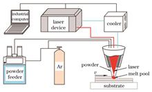
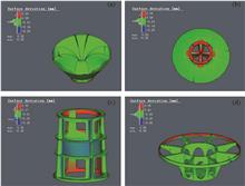
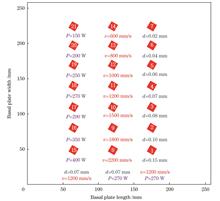
ObjectiveAdditive manufacturing (AM) is a revolutionary digital manufacturing technology. Compared with traditional manufacturing techniques, components fabricated using AM exhibit high geometric freedom and excellent performance. They have been widely used in aviation, aerospace, nuclear energy, and other fields. Laser directed energy deposition (LDED) is one of the most widely employed manufacturing technologies. Currently, problems, such as porosity, cracking, deformation, and the precipitation of brittle phases, still exist in certain L-DED components, especially high-entropy alloy (HEA) components. Revealing the formation mechanism of the L-DED process in HEAs is of great significance for macro-defect and microstructure regulation. However, the laser directed energy deposition process is accompanied by complex physicochemical phenomena such as extremely high temperatures, vaporization, rapid melting, and solidification. However, it is challenging to examine this mechanism experimentally. To reveal the formation mechanism of HEAs, a numerical model for the L-DED process of AlCoCrFeNi HEAs is developed. This model makes it possible to analyze the molding process from melt pool data, which are difficult to observe directly. We hope that our findings will aid in the study of the physical processes of L-DED and the regulation of the microstructure of components.MethodsIn this study, a numerical model was developed based on the coupled method of the Lagrange discrete-phase model (DPM), volume fraction of fluid (VOF) method, and adaptive laser body heat source model. The physical processes involved in the model mainly include the interactions among air, powder, laser, and metal. The interface between the deposited layer and the air was calculated and tracked using the VOF method. The enthalpy?porosity method was used to simulate the melting and solidification of the metal phase. Simultaneously, the DPM was used to characterize the motion of metal powders, and the collisions between particles were neglected. When the particles came in contact with the melt pool, the momentum, energy, and mass carried by the particles were transformed into the momentum, energy, and mass of the metal phase in the form of source terms using the coupled DPM-VOF model. Additionally, a Gaussian body heat source with adaptive adjustment of the range of action was used to simulate the interaction between the laser and the deposited layer. Subsequently, the developed model was solved using the finite-volume method. Finally, single- and four-layer samples were fabricated for the model validation and microstructural observations.Results and DiscussionsA comparison between the simulation and experimental results shows that the developed model exhibits high reliability (Fig. 7). The simulation results show that the melt pool is mainly affected by gravity, Marangoni force, and powder particle impact effects during the L-DED process. The impact of the particles interrupted the convection mode at the center of the melt pool (Figs. 10 and 11), which has an important effect on the distribution of the flow and temperature fields in the melt pool. Additionally, during the formation of the thin-walled AlCoCrFeNi HEA samples, a columnar-to-equiaxial transition (CET) is observed in the microstructure from the bottom to the top of the sample (Fig. 17). According to the simulation results, the maximum temperature gradient at the solid?liquid interface at the back of the melt pool decreases from 1.26×10⁶ K/m in the first layer to 5×10⁵ K/m in the fourth layer (Fig. 14), whereas there is no significant change in the distribution of the solidification rate (Fig. 16). Hence, the average G/R value at the solid?liquid interface at the back of the melt pool decreases from 5.16×10⁹ to 1.06×10⁹ (Table 7). According to the theory of non-equilibrium solidification of alloys, when the G/R value decreases, the tendency of the alloy to form columnar crystals during solidification decreases, and the tendency to form equiaxial crystals increases, which explains the phenomenon of CET in the AlCoCrFeNi samples.ConclusionsIn this study, a numerical model of the L-DED forming process is developed to simulate the machining of single-track and thin-walled structures of an AlCoCrFeNi high-entropy alloy. The model shows high reliability based on a comparison of the geometric data between the simulation and experimental results. According to the simulation results, the flow field of the melt pool is mainly affected by gravity, the Marangoni effect, and the impact of the particles. The intermittent impact of the particles on the melt pool is mainly concentrated near the center of the melt pool, which interrupts the convection mode in this region and thus affects the temperature distribution of the melt pool. Consequently, the influence of particles on the temperature and flow distributions of the melt pool cannot be ignored. Additionally, the microstructure of L-DED AlCoCrFeNi thin-walled samples shows a transition from columnar to equiaxial crystals from the bottom to the top, which is mainly affected by the solidification rate (R) and temperature gradient value (G) along the back edge of the melt pool. According to the simulation results, the average G/R value at the solid?liquid interface at the back of the melt pool decreases from 5.16×10⁹ in the first layer to 1.06×10⁹ in the fourth layer. The change in the solidification conditions is the main reason for the CET transformation of the samples. Our study provides a method for exploring the relationship between the forming process and microstructure of parts fabricated via L-DED.
Dec. 11, 2024Vol. 51 Issue 24 2402301 (2024)
Luotian Tang, Fencheng Liu, Qifan You, Wugui Jiang, Fenggang Liu, Xiaobin Yu, Chuankui Zhang, and Zhou Zeng
ObjectiveThe aerospace industry has a natural demand for lattice structures that combine lightweight design features, high stiffness, and strong energy absorption capabilities. As engineering applications continue to expand, selective laser melting (SLM), which is one of the most promising additive manufacturing (AM) methods for TC4 alloy lattice structures, has become a key technology. Compression loads are the main cause of lattice structure failure, and improvements in the compression performance of lattice structures have attracted widespread attention from scholars. However, the impact of structural parameters on the compression performance of lattice structures is not yet clear, and reports on how the strut angle affects the compression performance of lattice structures are few. To improve the ability of lattice structures to resist out-of-plane loads is of great engineering significance in studying the influence of the strut angle on the compression performance of lattice structures, for further lattice structure optimization.MethodsLattice structures with strut angles of 60°, 90°, and 120° were fabricated using SLM. Quasistatic compression experiments were conducted on the samples at room temperature, and finite element analysis was performed to describe the deformation behavior and failure modes of each sample during compression. The fracture modes of lattice structures with different strut angles were characterized through fracture surface analysis.Results and DiscussionsIn Fig. 3, the overall performance of the lattice structure is optimal for a strut angle of 60°. The compressive strength reaches 391 MPa, which is 36% and 25% higher than those of the 90° and 120° samples, respectively. The energy absorption capacity is 17.8 MJ/m3, which is 9.5 MJ/m3 and 6.9 MJ/m3 higher than those of the 90° and 120° samples, respectively. The energy absorption efficiency is 64.3%, which is only 0.1 percentage point lower than that of the 120° sample. On the other hand, adjusting the strut angle can change the stress state of the α/α′ martensite phase inside the lattice struts (Fig. 8). The shear stress decreases continuously within the range of (π/3, π/2) and increases continuously within the range of (π/2, 2π/3). The minimum value of shear stress is 0 when θ is π/2, that is, when the strut angle is 90°. A larger shear stress promotes dislocation slip and enhances the resistance of the lattice structure to plastic deformation, thereby explaining the phenomenon that the equivalent plastic strain of the lattice structure decreases first and then increases with a gradual increase of the strut angle. Combining the bending moment calculation formulas, the bending moments of the 60°, 90°, and 120°samples were found to be 1732 N·mm, 2365 N·mm, and 5366 N·mm, respectively. This means that as the strut angle increases, the finite relative rotation angle between two infinitely adjacent cross-sections decreases when the cross-section of the lattice strut reaches the plastic flow stage. The larger bending moments of the 90° and 120° samples cause all the lattice struts in the lattice structure to be close to the compressive strength limit of the TC4 alloy. At this point, any strut fracture immediately leads to the rapid failure of the structure along the maximum shear stress band. However, in the 60° sample, because of the smaller bending moment experienced by the struts, the middle and lower layers of the lattice are not close to the compressive strength limit when the upper lattice is about to fail. After the upper lattice struts fracture, the equivalent stress concentration in the middle and lower layers of the lattice is partially relieved, and the upper lattice continues to undergo plastic deformation, ultimately resulting in failure caused by a layered collapse. This indicates that with a larger strut angle in the BCC lattice structure, the more pronounced is the shear failure exhibited by the lattice structure. The fracture surfaces of all samples were composed of rough planes accumulated by a large number of dimples and smooth areas of quasi-cleavage planes, indicating the mixed ductile and brittle fracture mechanism of the lattice structure (Fig. 13).ConclusionsThe results of the quasi-static compression tests and finite element analysis showed that the energy absorption capacity, energy absorption efficiency, and compression performance of the lattice structure first exhibits a decreasing and then an increasing trend with an increase in the strut angle. The comprehensive performance was optimal, for a strut angle of 60°, reaching 17.8 MJ/m3 (energy absorption capacity), 64.3% (energy absorption efficiency), 391 MPa (compressive strength), and 6.7% (equivalent plastic strain). A positive correlation exists between the strut angle and the plastic bending moment of the lattice struts. The bending moments of the 60°, 90°, and 120° samples were 1732 N·mm, 2365 N·mm, and 5366 N·mm, respectively. The lattice strut in the 60° sample experienced a smaller bending moment, resulting in a failure mode of layered collapse. In contrast, the 90° and 120° samples exhibited shear failure modes. An increase in the bending moment makes the lattice structure more prone to shear failure. The fracture mechanism of the lattice struts in all the samples was a mix of ductile and brittle fracture mode.
Dec. 06, 2024Vol. 51 Issue 24 2402302 (2024)
Tianyu Chen, Jie Bao, and Yong Kong
ObjectiveTo verify the engineering application of selected laser melting (SLM) technology in aerospace products, systematic verification is conducted in terms of aspects such as dimensional tolerances, testing performance, and environmental testing. Owing to the high temperature gradient around the molten pool under the action of a moving heat source and the deposition undergoing heating and cooling cycles, SLM technology is prone to residual stress and deformation during part forming, thereby affecting the accuracy and quality of the parts. Therefore, it is necessary to accurately predict and control the residual stress and deformation of the parts. Conventional methods used to control the residual stress and deformation have limitations in their applicability to various characteristic parts. Therefore, more effective methods are necessary to suppress part-forming deviations and improve the quality of SLM-formed parts.MethodsTaking a satellite-mounted antenna component as the research object, an SLM process simulation is performed using Simufact Additive. The simulation adopts a pure structural algorithm called the inherent strain method. The inherent strain value is calculated based on the process parameters, scanning strategy, and material characteristics, thereby establishing displacement and stress field analysis models for part forming and predicting the forming deviation, equivalent stress, and failure position of the sample. As the inherent strain method cannot accurately determine the anti-deformation amount, it can only be approximated with reasonable accuracy through an iterative method. The final shape error of the formed part can be calculated using a recursive formula for the anti-deformation structure. When the allowable shape error is satisfied, the iterative calculation ends, and the final anti-deformation shape function is obtained. Finally, the simulation results are experimentally verified, and performance and environmental tests are conducted.Results and DiscussionsThis study fully verifies the environmental adaptability and functional reliability of SLM-formed antenna components through experiments, performance testing, and environmental testing, achieving a transition from traditional performance to functional application and laying the foundation for the large-scale application of SLM technology in aerospace products. The measured antenna components meet the design envelope size requirements (Table 4). Further, the actual forming size of the measured hole-shaped features is smaller than the design size (Table 5), and the actual forming size of the measured thin-walled features is larger than the design size (Table 6). The measured hardness data of the samples in the deposited and heat-treated states show a decrease after heat treatment (Table 7). The measured tensile test data of the samples in the deposited and heat-treated states show that heat treatment can change the mechanical properties of SLM-formed parts. The strength of the parts decreases after heat treatment; however, the plastic properties improve (Table 8). After environmental testing, no evident deformation, damage, or other abnormal phenomena are observed in the appearance or structure of the antenna components. Meanwhile, the standing-wave test values are stable and satisfy the indicator requirements (Figs. 5?7). The inherent strain method can accurately predict the forming deviation and equivalent stress of the parts. The method of significantly improving the accuracy of formed samples through the reverse deformation method differs from conventional process methods and is rarely used in SLM technology. This method significantly improves the forming accuracy of the parts and lowers the forming risk by reducing the forming deviation by at least 39.47% and equivalent stress in part forming (Table 10).ConclusionsThe inherent strain method can accurately predict the forming deviation and equivalent stress of SLM-formed parts. By iteratively optimizing the anti-deformation parts using the anti-deformation method, the forming accuracy of the parts is significantly improved while the forming risk is lowered to a certain extent. The AlSi10Mg deposited samples exhibit superior mechanical properties compared to commonly used aluminum alloys (2A12, 5A06, and 6061), in addition to superior plastic properties. If the tensile and yield strength requirements are not high, the heat-treated samples can be used, and their plastic properties are approximately equivalent to those of commonly used aluminum alloys. The dimensional tolerance of the SLM-formed antenna components meets the design requirements; the mechanical and electrical performance standards are also satisfied. Through environmental testing, this study demonstrates the feasibility of SLM technology in aerospace products .
Dec. 25, 2024Vol. 51 Issue 24 2402304 (2024)
Zhiyong Li, Dongxue Han, Shikun Jiao, Quanfu Liu, Cangrui Yu, Yuanhong Qian, Rong Chen, and Yang Liu
SignificanceAerospace pertains to the navigation activities of aircraft in the solar system beyond the Karman line. It reflects the ability of human access to space as well as the exploration, utilization, and governance of the latter. Thus, space frontier leadership and industrial initiatives are demonstrated. Space equipment has become a primary factor that determines space capabilities and strategic support for national development. Motivated by space activities, such as near-Earth to deep-space and single to multiple missions, researchers are attempting to develop precise, miniaturized, and high-performance space equipment by further improving space components. The production of aerospace components presents severe challenges, such as difficulty in manufacturing complex structures and processing high-performance materials.Additive-manufacturing technology is advantageous for manufacturing high-performance materials as well as complex and custom-designed structures, thus providing a solution for the high-quality manufacturing of advanced aerospace components. Simultaneously, the high flexibility of additive manufacturing is suitable for the evolving varieties and small quantities of aerospace components. Additive manufacturing has become a key technology in the transformation and upgradation of the aerospace industry. Based on the heat-source type, additive-manufacturing technology can be classified into arc, electron-beam, and laser additive manufacturing. The light-spot diameter of arc additive manufacturing is in the millimeter scale, which yields a high deposition efficiency but a low forming accuracy (approximately 100 μm). In electron-beam additive manufacturing, the spot radius is 100 μm, the deposition efficiency is lower than that of arc additive manufacturing, and the forming accuracy can be up to 0.13 μm higher. In laser additive manufacturing, the spot radius is typically tens of micrometers, the deposition efficiency is lower than that of electron-beam additive manufacturing, and the forming accuracy is high, i.e., up to 0.02 μm. Furthermore, it offers accurate energy control and requires a small heat input. Laser additive manufacturing is particularly suitable for the precise formation of complex aerospace components and is the most widely adopted approach in the aerospace field.The engineering-application degree of laser additive manufacturing in the aerospace field is determined by the process, equipment, and production line. Laser additive manufacturing guarantees the high-quality manufacturing of aerospace components. The equipment used for laser additive-manufacturing equipment determines the process and is the hardware basis for the high-quality manufacturing of aerospace components. The production line for laser additive manufacturing is a platform for promoting the high-quality production of aerospace components. Owing to demands in the aerospace field, the technology, equipment, and production lines associated with laser additive manufacturing are developing rapidly. The progress of laser additive manufacturing in the aerospace industry must be summarized to guide the further application of laser additive-manufacturing technology and ultimately promote the development of aerospace laser additive manufacturing.ProgressTo accommodate complex-structure and flexible manufacturing in the aerospace field, the technology, equipment, and production lines associated with laser additive manufacturing are being tested. Based on the typical structural characteristics of aerospace components, this review describes the progress of laser additive-manufacturing technology in the high-quality formation of aerospace components. Additionally, the challenges and solutions of laser additive-manufacturing technology applications are summarized. Furthermore, guided by the aerospace demand for laser additive manufacturing, this review introduces the development status and design direction of selective-laser-melting and laser-directed energy-deposition equipment. Based on the background of the multivariate and variable batch manufacturing of aerospace components, this review describes the application of additive-manufacturing lines in high-efficiency, low-cost, and high-reliability manufacturing. Additionally, the application of laser additive manufacturing in the aerospace field is introduced and analyzed in terms of technology, equipment, and intelligent production lines. Subsequently, the development prospects of laser additive manufacturing are forecast, with emphasis on its application in the aerospace field.Conclusions and ProspectsThe vigorous development of China space industry has promoted the development of high-performance, multifunctional, and large-scale components. The capacity of laser additive manufacturing should be further investigated to provide continuous support to the space industry. Additionally, the synergy among the technology, equipment, and production line associated with laser additive manufacturing should be strengthened to promote the application of laser additive manufacturing in the aerospace field. Additionally, the composition design of high-temperature materials and advanced structures dedicated to laser additive manufacturing can be performed. Furthermore, high-end equipment incorporating key technologies (e.g., for ensuring the stability of large-format wind fields, the reliability of optical system, and the control accuracy of the motion system) of large-scale laser additive-manufacturing equipment and flight printing can be designed. Finally, deep learning, digital twins, and artificial intelligence can be applied to production line of laser additive manufacturing.
Dec. 09, 2024Vol. 51 Issue 24 2402305 (2024)
Meng Deng, Xin Zhou, Xing Cheng, Ting Zhang, Xuede Wang, and Ting Ju
ObjectiveTo ensure the forming quality and stability of laser powder bed fusion (LPBF), an online monitoring technology must be developed. Using diodes to obtain the radiation intensity of molten pools can accurately reflect their temperature and other important information in real time. It is an economical and efficient method for monitoring the forming process and features low cost, high sensitivity, rapid response, and a small sample size. However, the associated analysis is limited and challenging; therefore, the mapping relationship between the radiation monitoring data of molten pools and the forming process must be analyzed. Process parameters significantly affect the performance of metal additive-manufactured components. Most current production process parameters are not necessarily optimum, which implies that they may cause manufacturing defects. Determining the optimal forming process parameters for each metal via numerous forming experiments is time consuming and labor intensive. Therefore, by analyzing the mapping relationship between the process parameters and radiation intensity of a molten pool, quality monitoring and process adjustments can be realized through online monitoring. This can prevent defects or even failures caused by process parameters and significantly reduce the time, manpower, and financial resources required for forming experiments. Although the radiation intensity of molten pools and the related process parameters have been investigated extensively, a method for adjusting the process parameters directly using the radiation intensity of the molten pool has not been devised. Therefore, the effects of different process parameters on the radiation intensity of molten pools must be investigated to identify and adjust the process parameters.MethodsTo determine the mapping relationship between the process parameters and radiation intensity of molten pools, three methods for analyzing the radiation intensity of molten pools were proposed: the deviation integral curve, the probability density function curve, and relative heat-map analysis methods. Three groups of powder bed forming experiments with different process parameters were designed, and the radiation-intensity data of each sample were obtained. After performing data preprocessing via data segmentation, noise reduction, and feature extraction, single-layer and multilayer radiation-intensity data-analysis methods were used for comparative analysis.Results and DiscussionsAs laser energy increases, the temperature of the molten pool increases and the liquid-phase duration is prolonged. The powder around the droplet is easily inhaled, thus resulting in more powder at this position and less powder at the next position compared with the normal condition; therefore, the temperature of the molten pool fluctuates significantly, thus causing the signal obtained by the diode to fluctuate considerably. When the scanning interval is reduced to 0.06 mm, or the scanning speed is reduced to 1000 mm/s, or the laser power is increased to 350 W, i.e., the corresponding laser energy is increased from 93.75 to 281.25 J/mm3, the molten-pool stability is reduced and the fluctuation range of the diode signal increases. Therefore, the corresponding single-layer deviation integral curve fluctuates more significantly , the dispersion degree of the multilayer deviation integral curve increases, the shape of the single-layer probability density function curve is short and round, and the average distribution of the multilayer probability density function curve becomes increasingly wider. The relative heat map shows a high portion of non-green areas.ConclusionsA molten-pool radiation intensity analysis method was proposed to analyze the radiation intensity of a molten pool under different process parameters from different perspectives, and a unified influence law was obtained. As the scanning distance and scanning speed decrease and the laser power increases to a certan range, that is, the laser energy density increases to a certain extent, the radiation intensity of the molten pool generally increases, the fluctuation degree of single-layer data increases, and the distribution range of multilayer data increases. Our study has realized the recognition of abnormal layer, but the influence of abnormal layer and the measures to avoid it have not been studied, so they should be considered to be explored in the future. Additionally, the effects of metal vapor and splash on the online monitoring of molten-pool radiation intensity shall be considered.
Dec. 06, 2024Vol. 51 Issue 24 2402306 (2024)
Yishen Wang, Mina Zhang, Dafeng Wang, Guangyi Zhang, Yuhang Zhou, Jing Wang, and Wenwu Zhang
SignificanceMetal melting and forming involves heating one or more types of metal to their melting point or above, allowing for alloying or metallurgical bonding. This process is utilized in methods such as welding, surface cladding, and additive manufacturing. Metal melting and forming technology has always advanced alongside human progress. At present, this technology is integral to aerospace, marine, and high-end equipment manufacturing, facilitating the formation, joining, and repair of metal structural components. However, the large temperature gradients that occur during metal melting and forming can have varying effects on structural metal parts.Welding, surface cladding, and additive manufacturing technologies involve the use of high-energy-density heat sources to melt metal materials in a confined area. The rapid cooling rate in these processes results in significant temperature gradients within the melt pool. This can lead to the predominant formation of columnar or dendritic crystal grains, which are prone to cracking and porosity under thermal stress, significantly affecting the performance of the workpiece. Regulating the internal structure of metal melting and forming parts and suppressing internal defects are critical issues in these processes. To address these challenges, researchers have proposed applying external physical fields?including electric, magnetic, and ultrasonic fields?during the metal solidification process. These fields interact with the molten metal to regulate its solidification structure. Initial studies have shown that ultrasonic vibration can refine grains, inhibit segregation, and reduce temperature gradients, thus positively impacting grain growth and solidification processes. Currently, the integration of ultrasonic vibration as an external energy field into metal melting and forming technology has become a research hotspot, offering potential solutions to enhance the quality and performance of metal parts.This study presents a discussion and summary of the recent progress and challenges in ultrasonic vibration-assisted metal melting and forming technology, focusing on its combined application with welding, surface cladding, and additive manufacturing. First, we briefly introduce the mechanism of ultrasonic vibration in metal melting. Then, we discuss the effects of ultrasonic vibration on metal melting and forming technology, considering different additive modes based on the ultrasonic transmission characteristics. Next, we explore the role of ultrasonic vibration in regulating the organization and properties of molded parts for casting, welding, surface cladding, and additive manufacturing processes. Finally, we identify the key scientific issues and technical challenges associated with ultrasonic vibration-assisted metal melting and forming technology.ProgressIn metal melting and forming technology, the excessive temperature gradients and rapid cooling rates often lead to significant non-equilibrium solidification structures. This results in issues such as grain size variation, solute segregation, and stress concentration. Ultrasonic vibration, a high-frequency mechanical vibration, induces several effects in molten metal, including cavitation, acoustic flow, mechanical, and thermal effects. Finite element simulation and experimental observations have revealed that these effects can effectively break down coarse grains, enhance melt flow, and reduce temperature gradients (Figs. 1?3).However, the high temperatures during metal solidification can significantly impact the working life of ultrasonic components. This study categorizes the various methods of incorporating ultrasonic vibration into metal melting and forming technology into contact and non-contact methods. Contact methods are further subdivided into below, side, and above, on the basis of the direction of ultrasonic vibration propagation in the metal melt. In the repair process of a small area, the time span is short; hence, the effect of ultrasonic vibration in different directions on the molding area is minimal. However, in the metal manufacturing process of a large area, the prolonged solidification process can intensify the impact of ultrasonic vibration, leading to significant differences in the molded parts based on the direction of ultrasonic vibration. This study compares the advantages and shortcomings of these methods in the application process (Table 1).Welding, surface cladding, and additive manufacturing are three typical metal melting and forming technologies. This study presents a literature review to explore the effects of ultrasonic vibration on these technologies from two perspectives: the microstructure and physical properties of the molded parts. The effects include gas exclusion, grain refinement, stress reduction, and enhancement of mechanical properties and corrosion resistance (Table 2).Conclusions and ProspectsIn this study, we review the research progress of ultrasonic vibration-assisted metal melting and forming technology. We discuss the mechanism of ultrasonic vibration in metal melts, various methods of adding ultrasonic vibration, and effects of ultrasonic vibration on the microstructure and physical properties of molded parts in welding, surface cladding, and additive manufacturing processes. This study summarizes the impact of ultrasonic vibration on the forming quality of various metal melting and forming technologies, seeking to aid the realization of high-quality metal melting and forming. We also aim to promote further research and application of ultrasonic vibration-assisted metal melting and forming technologies.
Dec. 11, 2024Vol. 51 Issue 24 2402101 (2024)
Haojie Zhang, Zhigang Chen, Wei Feng, Jixin Hou, Yunhe Yu, Chaohui Zhu, Hong Tan, and Zhixin Xia
ObjectiveTi-based amorphous alloys have received significant attention owing to their low density, high specific strength, superior corrosion resistance, and relatively low fabrication cost, which render them promising for widespread application in fields such as national defense, aerospace, sports, and medicine. However, they present some mechanical performance issues such as low plasticity. Studies have shown that introducing heterogeneous structures into metallic materials can improve their mechanical properties. Performing laser remelting on Ti-based amorphous alloys can create gradient heterogeneous structures in their depth direction, thus improving their mechanical performance. Currently, studies regarding the introduction of heterogeneous structures into amorphous alloys via laser remelting are limited. In this study, by performing microscopic analyses and numerical simulations of temperature fields, we investigate the microstructure evolution of laser-re-melted Ti-based amorphous alloys and its effect on their mechanical properties. The aim of this study is to provide experimental and theoretical support for understanding the mechanism of laser-induced heterogeneous structures and its effect on the properties of amorphous alloys.MethodsWe prepare Ti-based amorphous alloys via vacuum suction casting, followed by laser remelting. First, the microstructure of the laser-re-melted Ti-based amorphous alloys is analyzed using micro-area X-ray diffraction (XRD) and scanning electron microscope (SEM). Subsequently, a numerical simulation of the temperature field during laser remelting is conducted to analyze the thermal histories of different regions after laser remelting. Microstructure analyses and temperature-field simulations are performed to elucidate the effect of laser remelting on the structure of Ti-based amorphous alloys. Subsequently, hardness testing is performed along the depth direction after laser remelting to examine the trend of mechanical-property changes induced by the heterogeneous structure. Finally, various processes are employed for the laser remelting of Ti-based amorphous alloys, and the effects of heterogeneous structure variations on the plasticity of Ti-based amorphous alloys are revealed via uniaxial tensile tests and microstructure analyses.Results and DiscussionsThrough laser remelting, a gradient heterogeneous structure comprising a melt-pool amorphous structure, heat-affected zone amorphous composite structure, and substrate amorphous structure is formed in the depth direction of the Ti-based amorphous alloy (Figs. 4 and 5). Microstructure analysis combined with a numerical simulation of the temperature field reveals the thermal history for different regions, thus elucidating the formation mechanism of the amorphous structure with a free-volume gradient distribution within the melt pool. Additionally, the effects of different residence time, heating rates, and cooling rates within the heat-affected zone on the nucleation and growth behavior of crystalline phases are analyzed. The microhardness of the laser-re-melted Ti-based amorphous alloy clarifies the effects of the pattern and mechanism of the gradient heterogeneous structure on the microhardness. Furthermore, appropriate laser-processing parameters can induce the proliferation of shear bands, thereby enhancing the plasticity of Ti-based amorphous alloys.ConclusionsThe effects of laser remelting on the microstructure and plasticity of Ti-based amorphous alloys are investigated via finite-element simulation, microstructural analysis, and mechanical-property analysis.1) Finite-element simulation is performed to analyze the temperature distribution during laser remelting of Ti-based amorphous alloys. The samples undergoes different thermal histories at various depths, thus resulting in distinct regions: a melt pool, heat-affected zone, and substrate, each exhibiting different structural evolution behaviors.2) The melt pool exhibits a high cooling rate, thus resulting in an amorphous structure. However, as the depth of the melt pool increases, the cooling rate decreases gradually, thus resulting in a gradient amorphous structure with reduced free-volume content and increased hardness. By contrast, the heat-affected zone shows reduced residence time and peak temperature with increasing depth, thus resulting in a decrease in the gradient of the crystalline-phase size but an increase in quantity. The presence of crystalline grains hinders the single propagation of shear bands, thereby resulting in the highest hardness in this region. The amorphous structure of the substrate area remains unchanged.3) The laser remelting of Ti-based amorphous alloys results in a gradient heterostructure with various structural and performance gradients. The synergistic effects of different gradient structures are expected to suppress the expansion of single shear bands, thereby enhancing the plastic-deformation capability of amorphous alloys.4) Different laser-processing techniques will alter the microstructure and dimensions of re-melted samples in various regions, thus inducing the corresponding changes in the gradient heterostructures. Plastic-deformation analysis based on different gradient heterostructures indicates that a rational gradient heterostructure can improve plasticity, whereas an irrational gradient structure may worsen it. Future studies shall focus on optimizing laser processing to control gradient heterostructures, thereby further enhancing material plasticity.
Dec. 09, 2024Vol. 51 Issue 24 2402103 (2024)
Yanchuan Tang, Jinfeng Zhang, Mingxue Shen, Haitao Jiao, Dejia Liu, and Xingchang Tang
ObjectiveWith the continuous increase in speed and axle load of heavy haul trains, the deterioration of bainitic steel rails is exacerbating, posing serious safety risks to railway transportation. The prompt resolution of surface damage repair issues of bainitic steel rails is imperative. While surface additive manufacturing repair methods such as laser deposition are suitable for damages of various sizes and exhibit good bonding between the repair layer and base material, they tend to form a large amount of brittle martensite structure in the repair layer and heat-affected zone. By employing preheating treatment temperature field control methods before laser deposition, the formation of martensite during the laser deposition process can be hindered. Combined with subsequent isothermal heat treatment, a repair layer primarily consisting of bainitic structure can be achieved, potentially leading to high-quality, cost-effective, and efficient surface repair of bainitic steel rails. This study systematically investigated the microstructural evolution and mechanical properties of laser-deposited ultra-high-strength steel repair layers under different temperature field conditions (laser deposition state, preheated at 280 ℃ and 320 ℃), The focus was on analyzing the effects of different laser deposition thermal cycling processes on the relative proportions of bainite/martensite structures and substructural characteristics in laser-deposited ultra-high-strength steel, to elucidate the relationship between microstructural features and mechanical properties. These research findings have certain guiding significance for practical applications of laser deposition in heavy-haul steel rail repairs.MethodsUtilizing laser deposition technology, a test steel repair layer is fabricated on the 30CrMnSiA medium carbon alloy steel substrate, using the compositions of the substrate and test steel detailed in Table 1. A constant-temperature preheating stage is positioned beneath the substrate (as shown in Fig. 1) to maintain the temperature of the substrate and deposited layers above the designated preheating temperatures of 280 ℃ and 320 ℃. Following the completion of each metal deposition layer, the sample is allowed to cool to the specified preheating temperature before commencing deposition of the subsequent metal layer, followed by natural cooling to room temperature. For comparative analysis, laser-deposited state samples are generated by performing laser deposition using identical process parameters. X-ray diffraction (XRD) analysis is employed to examine the phases present in the samples. The color metallographic method is utilized for statistical assessment of the proportions of bainite and martensite structures within the samples. Field emission scanning electron microscope (FESEM) is utilized along with an electron backscatter diffraction (EBSD) probe, to analyze the crystal orientation and substructure of the microstructure of the samples, with data processing performed using the AZtecCrystal software. Tensile properties of the samples are evaluated using an electronic universal testing machine.Results and DiscussionsThe XRD results (Fig. 2) reveal that the samples preheated at 280 ℃ and 320 ℃ exhibit 82% and 46% higher retained austenite (RA) content, respectively, compared to laser-deposited state samples. The detailed microstructure observed through SEM (Fig. 4) indicates that the laser-deposited state samples predominantly exhibit a lath-like martensite microstructure characterized by large-sized packets. In the sample preheated at 280 ℃, the bainite microstructure had a lath-like morphology with relatively large-sized packets and abundant blocky martensite/austenite mixed microstructures positioned between the bainite packets with various orientations. In the sample preheated at 320 ℃, the bainite microstructure displays a combination of lath-like and leaf-like morphologies, with the leaf-like bainite having an average width of around 1.2 μm. Notably, the leaf-like bainite effectively segregates the original austenite grains. The inverse pole figure (IPF) mapping results (Fig. 5) reveal that in the laser-deposited state samples, numerous martensite packets can traverse the entire original austenite grains, and the average size of the packet is the largest, reaching up to 15.5 μm. For the sample preheated at 280 ℃, most of the bainite/martensite packets grew parallel throughout the entire original austenite grains, forming a relatively large-sized packet, with an average size of 13.5 μm, which is a slight reduction compared to the laser-deposited state. In contrast, for the sample preheated at 320 ℃, the original austenite grains were segmented into multiple bainite/martensite packets with different orientations. The size of the packets significantly decreased, with an average size of 8.5 μm, which is 55.0% of the size observed in the laser-deposited state. Based on the band contrast (BC) maps and distribution of BC values obtained from the EBSD results (Fig. 6), precise content of bainite and martensite in the samples at different preheating temperatures can be obtained. In the sample preheated at 280 ℃, the proportion of bainite and martensite is close, accounting for approximately 47.9% and 52.1%, respectively. In contrast, the bainite content (62.5%) in the sample preheated at 320 ℃ is significantly higher than the martensite content (37.5%). Tensile properties results (Fig. 9) show that compared to the laser-deposited state sample, the sample preheated at 280 ℃ exhibits higher elongation (8.4%, corresponding to an increase of 23.5%), and the ultimate tensile strength is slightly lower than that of the laser-deposited state sample (1491 MPa). For the sample preheated at 320 ℃, the ultimate tensile strength (1346 MPa) is approximately 10.0% lower than that of the laser-deposited samples, but elongation is significantly higher (57.4%). Particularly, the uniform elongation is more than 115% higher than that of the laser-deposited samples, indicating a better strength-ductility combination.ConclusionsThis study systematically investigated the microstructure and mechanical property evolution of laser-deposited ultra-high strength steel repair layers. The focus was on analyzing the influence of thermal cycling processes on the relative proportion of bainite/martensite structures, substructure characteristics, and mechanical properties in three different conditions: direct laser deposition, preheating at 280 ℃, and preheating at 320 ℃. The main conclusions are as follows: (1) The microstructure of the laser-deposited experimental steel mainly consists of martensite with a small amount of retained austenite (volume fraction is 5.65%). However, the microstructure of the experimental steel subjected to preheating during the laser deposition process is primarily composed of bainite and martensite dual-phase structure, with a significant increase in the content of retained austenite compared to the laser-deposited state (increase of 82% and 46% for preheating at 280 ℃ and 320 ℃, respectively). (2) In the 280 ℃ preheated experimental steel, the bainite morphology is mainly lath-like, with relatively large-sized packets (13.5 μm), and abundant blocky martensite distributed between the bainite packets. As the preheating temperature increased to 320 ℃, the experimental steel showed a mixed morphology of lath-like and leaf-like bainite microstructure, with the leaf-like bainite effectively segregating the original austenite grains. The size of the bainite packet (8.5 μm) was significantly reduced, and a small amount of martensite lath was distributed between the bainite packets. (3) The as-deposited experimental steel exhibited the highest tensile strength (1501 MPa) but the lowest elongation (only 6.8%), with a fracture mode characterized by typical quasi-cleavage. After preheating treatment, the plasticity was significantly improved with only a slight decrease in tensile strength (less than 10.0%). The elongation of the experimental steel preheated at 320 ℃ increased by 57.4% compared with that of the laser-deposited state, and the fracture mode transformed into microvoid coalescence fracture.
Dec. 11, 2024Vol. 51 Issue 24 2402104 (2024)
Runlong He, Xin Du, Xinyu Zhou, Qiang Wu, and Rongshi Xiao
ObjectiveGH3536 is a solid-solution-strengthened nickel-based superalloy with excellent corrosion resistance, oxidation resistance, thermal strength, and microstructural stability. 304 austenitic stainless steel exhibits excellent mechanical properties, strong corrosion resistance, and high strength, as well as incurs low cost. Both materials have been widely used in the aerospace field. Currently, selective laser melting (SLM) of these two materials is close to maturity. Laser welding technology has the advantages of accurate energy control, low heat input, and small welding deformation. It can be implemented in an atmospheric environment and involves flexible beam regulation. This technology is well established in the aerospace field and has been increasingly employed. Therefore, this study proposes the use of laser welding to connect SLMed GH3536 and SLMed 304, two dissimilar materials. Further, the weld structure and performance may be examined to confirm whether this approach combines the technical advantages of the two advanced laser manufacturing methods while reducing the manufacturing cost and process risk of 3D printing large-sized parts. This approach is expected to enable low-cost, high-quality manufacturing of large size components in the aerospace sector.MethodsThe welding equipment uses a fiber laser with a wavelength of 1060?1070 nm and a maximum output power of 6 kW. The core diameter of the transmission fiber is 200 μm, focal length of the fiber-coupled collimator is 200 mm, focal length of the focusing lens is 300 mm, and diameter of the focusing spot is 0.3 mm. The test materials are SLMed GH3536 and SLMed 304, and the butt-welding sample sizes of both materials are 50.0 mm × 50.0 mm × 3.8 mm. During the welding process, the laser beam is perpendicular to the surface of the plate, and the focus is located on the upper surface of the plate. Ar is used as a protective gas at a flow rate of 15 L/min. The angle between the axis of the protective gas nozzle and upper surface of the plate is 45°, and a welding test is performed using drag welding. The welding process uses a special fixture to maintain the sample plate butt without a gap, and the welding direction is perpendicular to the forming direction of the SLM process. The SLM stacking forming direction is defined as the Z-axis; the XOY plane is perpendicular to the forming direction, and the XOZ plane is parallel to the forming direction. The SLMed GH3536/SLMed 304 butt joint is obtained under a laser power of 2500 W and welding speed of 2 m/min. The weld microstructure is observed using a large depth-of-field microscope. The microstructures of the SLMed GH3536 and SLMed 304 substrates perpendicular to the forming direction and parallel to the forming direction are examined via electron back scattering diffraction (EBSD). The phase compositions and elemental distributions of the weld and base metal are measured and analyzed using X-ray diffraction (XRD) and energy spectrum analysis (EDS). A hardness tester is used to test the microhardness distribution of the weld. The indenter load of the hardness tester is 200 g, and the loading time is 15 s. The weld and two base materials are tested using a tensile test machine.Results and DiscussionsThe weld microstructure of SLMed GH3536/SLMed 304 is mainly composed of dendrites and equiaxed crystals. Near the fusion line of the 304 base metal, there exists a mixed-crystal region composed of fine crystal, equiaxed crystal, and dendrite. An unmixed zone with a width of 5?20 μm appeares near the fusion line of the 304 base metal. Some unmixed areas, resembling islands or peninsulas, are observed in the weld near the fusion line of the 304 base metal. The microstructure near the fusion boundary of GH3536 is composed of short dendrites and equal crystals, and characteristics of layer-by-layer solidification are observed. The central structure of the weld is mostly dendrite (Fig. 4). The elemental content of the weld is significantly different from those of the two substrates, and the elemental distribution curve near the weld fusion line changes sharply; however, the change inside the weld is small (Fig. 8). The weld is in the complete austenitic phase (Fig. 9). The average microhardness of the upper part of the weld is 195.6 HV, that of the middle part of the weld is 216.18 HV, and that of the lower part of the weld is 196.06 HV (Fig. 10). The tensile strength of the weld is 587.75 MPa, elongation reaches 55.5%, and the fracture mode is ductile (Fig. 11).ConclusionsA 3.8-mm-thick SLMed GH3536/SLMed 304 dissimilar material butt joint is successfully prepared using laser welding technology. The welded joints resemble nail heads in shape. The microstructure of the weld is dominated by dendrites and equiaxed crystals. The tensile test results show that the sample breaks at the SLMed 304 base metal, and the tensile strength reaches 587.75 MPa. The fracture mode is ductile.
Dec. 25, 2024Vol. 51 Issue 24 2402105 (2024)
Jiawen Ding, Fei Wang, Yuyao Li, Hanyu Zhang, Kuan Luo, Ming Tian, Chengshuang Zhang, and Yanling Bao
ObjectiveImpurity elements easily escape from carbon fiber insulation felts in high-temperature environments. They can pollute crystalline silicon during its growth in a monocrystalline silicon production furnace when such felts are used for insulation. Consequently, it needs further graphitization at high temperatures above 2200 ℃ to discharge non-carbon impurity elements, causing its carbon content (mass fraction) to increase to over 99%. The traditional electric heating graphitization technology is associated with several issues, including a long equipment preheating cycle, high energy consumption, harsh requirements for furnace materials, and the inability to sustain high temperatures. Laser heating technology has the characteristics of direct heating, a fast heating rate, and high energy utilization; therefore, it can effectively replace the traditional electric heating method. However, laser graphitization of carbon fiber insulation felts currently faces two problems, namely, an uneven distribution of the power density in the Gaussian beam irradiation area and large temperature gradient in the depth direction of the carbon fiber insulation felt. This study presents the use of laser graphitization technology for carbon fiber insulation felts. The influence of the laser process parameters on the chemical properties and microstructure of carbon fiber insulation felts is revealed, providing theoretical and technical guidance for using laser ultra-high-temperature graphitization to prepare these felts.MethodsPolyacrylonitrile (PAN)-based carbon fiber insulation felts are selected for this study. First, the basic principle of the laser graphitization of carbon fiber thermal insulation felt is introduced. The heat transfer model of the carbon fiber thermal insulation felt is analyzed, and the Gaussian beam emitted by a laser is shaped using a diffractive optical element (DOE). Second, characterization methods for different depth graphitization degrees and carbon contents of the carbon fiber insulation felts are proposed. Then, an experimental device for the laser graphitization of the carbon fiber insulation felt is set up, and a shaped flat-top laser is used to quickly heat the PAN-based carbon fiber felt. Finally, the carbon and sulfur analysis, Raman spectroscopy, and scanning electron microscope are used to analyze the carbon content, graphitization degree, and surface morphology of carbon fiber insulation felts, respectively. The results are used to explore the effects of the laser power density and irradiation time on the graphitization degree and carbon content of the carbon fiber insulation felts at different depths.Results and DiscussionsThe Gaussian beam emitted by the laser has a flatness of 92.46%, and the energy conversion efficiency is 88.94% after passing through the DOE shaping system, which can be approximately evenly distributed (Fig. 3). The laser graphitization process ensures that there is no ablation on the surface of the carbon fiber, while simultaneously obtaining a carbon fiber insulation felt with a carbon content of more than 99% and graphitization degree (R value) of 0.07. Generally, with an increase in the laser power density, the carbon content increases, and the difference in the radial carbon content decreases. When the laser power density is increased to 1120 W/cm2 (i.e., the irradiation temperature is 2210 ℃), the overall carbon content of the carbon fiber insulation felt reaches 99% (Fig. 7). The temperature of the carbon fiber insulation felt, as well as the order and graphitization degrees of the carbon material structure, increases with increasing laser power density. In addition, the distribution law of the radial R value of the carbon fiber insulation felt is essentially the same under different laser power densities, indicating that increasing the laser power density cannot improve the uniformity of the radial graphitization degree of the carbon fiber insulation felt (Fig. 9). When the irradiation duration is increased to 120 s, the graphitization degree of the carbon fiber insulation felt reaches its highest value, the R value is 0.07, and the graphitization effect is significant. Increasing the laser irradiation duration can alleviate the issue of the uneven radial graphitization of the carbon fiber insulation felt (Fig. 11).ConclusionsTo ensure uniform graphitization degree and surface morphology during the preparation of carbon fiber insulation felts, this study examines the carbon contents, chemical structures, and surface morphologies of the felts under different laser power densities and irradiation time. The experiments entail laser irradiation on PAN-based carbon fiber insulation felts. The results show that the laser graphitization process can produce a carbon fiber insulation felt with a carbon fiber content of more than 99% and graphitization degree (R value) of 0.07, while obviating ablation on the surface of the carbon fiber. In addition, the radial graphitization degree of the carbon fiber insulation felt becomes more uniform with an increase in the laser irradiation time. The findings of this study can provide theoretical and practical basis for the use of laser irradiation to prepare carbon fiber insulation felts.
Dec. 11, 2024Vol. 51 Issue 24 2402106 (2024)
Yanpu Li, Renchao Liang, Hanpeng Wang, Yi Zhang, and Haiying Wei
ObjectiveQuartz glass is a hard and brittle material with excellent physical and chemical properties; it is widely used in semiconductors, optics, aerospace, and automobiles. However, cutting quartz glass is challenging. For example, cutter wheel cutting causes edge collapse, microcracks, and residual stress, which affect the quality and strength of the glass. Picosecond lasers offer the advantages of high precision, zero contact, and high flexibility, thus rendering them suitable for cutting quartz glass. Therefore, based on the intensity-distribution characteristics of Bessel and Gaussian beams, this study uses a picosecond-pulse Bessel beam and a Gaussian beam to conduct a laser-ablation cutting experiment and a fragment cutting experiment on quartz glass, respectively, to investigate the process conditions of small edge chipping, small kerf loss width, and low surface roughness. Combining the above with the cutting speed, cross-sectional morphology, and processing cost, the applicable cutting thickness ranges of the two beams are determined to provide guidance regarding process selection in the picosecond laser cutting of quartz glass.MethodsThe materials used in this study are 1- and 2-mm-thick quartz glass. A Bessel beam with a non-diffraction distance of 815 μm in air, which is obtained using an axicon, is used. First, a 1-mm-thick quartz glass is cut using a picosecond Bessel laser-ablation material. The effects of the defocusing distance and hole spacing on the cross-sectional morphology are investigated using an optical microscope, and the edge-chipping sizes under different defocusing distances are measured to obtain the optimal hole spacing and defocusing distance. Second, internal modification and surface ablation are performed on the glass via picosecond Gaussian laser multiple scanning, and the 2 mm-thick quartz glass is cut into fragments. The effects of the single-pulse energy and overlap rate on the width of the kerf loss and the effect of the pulse width on the width of the phase-transition region are investigated. Finally, the cross-sectional quality of the quartz glass is investigated and analyzed, and an appropriate cutting process for glass with different thicknesses is determined based on the surface roughness, cutting speed, and cross-sectional morphology.Results and DiscussionsWhen cutting quartz glass using Bessel laser ablation, full ablation cutting can be achieved when the defocusing distance is -400 μm to -600 μm (Fig. 6). Therefore, the Bessel beam with a maximum non-diffracting distance of 815 μm in air can achieve the full ablation cutting of a 1.2-mm-thick quartz glass, and the full ablation cutting results in a better cross-section morphology and smaller edge chipping. The optimal defocusing distance is -500 μm (Fig. 7). When the hole spacing is 20 μm, the kerf edge is smooth, the cross-section morphology is favorable, the maximum cutting speed is 500 mm/s, and the surface roughness is 1.435 μm (Fig. 8). Linear cutting and curve cutting of 2 mm quartz glass are realized by performing Gaussian laser multiple scanning (Fig. 9). The surface roughness is 7.483 μm and the cutting speed is 30 mm/s. The kerf loss width increases with the single-pulse energy and overlap rate (Figs. 10 and 11). The width of the phase-transition region decreases with increasing pulse width (Fig. 12). The internal modification of the Gaussian laser removes more material than surface ablation (Fig. 13). As the focal depth increases, the average roughness of the three local modification regions from top to bottom decreases gradually from 8 μm to 4 μm (Fig. 14). From top to bottom, the cross-section of the quartz glass cut via Bessel laser ablation remains the same, the surface roughness decreases, and the cutting speed increases. To cut quartz glass, whose thickness is less than the non-diffraction distance of the beam, the Bessel beam should be the preferred light source. For quartz glass with a large thickness, the Gaussian laser multiple-scanning cutting process is superior to the high-cost Bessel laser-cutting process.ConclusionsIn this study, Bessel and Gaussian beam-cutting experiments of picosecond pulses are performed for quartz glass measuring 1 mm and 2 mm thick. The main conclusions are as follows:1) Full ablation processing can yield better cross-sectional quality. For quartz glass with a thickness less than the maximum non-diffracting distance, a Bessel laser can achieve high-quality and high-efficiency ablation cutting of the material. When a Bessel beam with a non-diffraction distance of 815 μm in air is used to cut quartz glass with a thickness of 1 mm, the edge chipping size can be controlled within 20 μm, and the cutting speed is 500 mm/s.2) Based on multiple scans, the thickness of the quartz glass cut by the Gaussian laser is significantly larger than the Rayleigh length of the beam. When a Gaussian beam cuts a 2-mm-thick quartz glass, the kerf loss width is within 10 μm; however, it changes significantly depending on the single pulse energy and overlap rate. The cutting speed is set to 30 mm/s.3) In the cross-section of quartz glass cut using a Gaussian laser, defects emerge and the surface roughness is high. Therefore, a Bessel laser should be the preferred processing light source when the glass thickness is within the non-diffraction distance of the beam. For quartz glass with a large thickness, the axicon typically used in industrial processing cannot generate a Bessel beam with a sufficiently long non-diffracting distance; in this case, a Gaussian laser can be a good alternative.
Dec. 10, 2024Vol. 51 Issue 24 2402107 (2024)
Jian Yang, Shuncun Luo, Pengfei Pei, Xiaonan Wang, Jia Song, and Hai Zhang
ObjectiveWith the wide application of deformed and cast aluminum alloy structural parts in automotive lightweight manufacturing, the microstructure and properties of welded joints of dissimilar aluminum alloys under various thicknesses, heat treatment states, forms of welded joints, welding methods, and welding process conditions have attracted increasing attention from scholars. However, due to the different thermal physical parameters of dissimilar aluminum alloys, the fluidity of the weld pool and the content and distribution of elements in various overlapping forms differ, leading to issues such as high porosity, segregation, and severe thermal cracking in the laser overlapped joints of A356/6082 dissimilar aluminum alloys. Therefore, this study investigates the macroscopic morphology, microstructure, and pore distribution and formation mechanism of A356/6082 welded joints with various overlapping forms in detail.MethodsIn this study, mechanical polishing, cleaning, and clamping are performed before welding. During the welding process, high-purity argon gas protects the upper surface of the molten pool, and the flow and keyhole behavior of the molten pool are monitored and analyzed using an Acuteye high-speed image V4.1 system. After the welding test, X-ray nondestructive testing, optical microscope (OM), and scanning electron microscope (SEM) are used to analyze the pore defects, microstructure, and precipitates in the weld. In addition, a tensile shear test of the welded joint is conducted on a universal test machine by removing the residual height of the weld surface and adding a shim at the position of the holding end of the tensile shear sample.Results and DiscussionsUnder the same laser line energy, compared to the overlapped joint when A356 is at the upper side and 6082 is at the lower side, there is a larger area of incomplete welding on the back of the overlapped joint when A356 is at the lower side and 6082 is at the upper side, the weld depth and width are reduced, and there are larger pores in the cross section (Fig. 3). When A356 is at the upper side and 6082 is at the lower side, the maximum pore diameter, average pore diameter, and porosity inside the weld are smaller than those when A356 is at the lower side and 6082 is at the upper side. With the same laser overlapping form, the maximum pore diameter, average pore diameter, and porosity in the weld increase with increasing laser power (Figs. 4 and 5). Due to the narrow overflow channel, long overflow path, and high cooling rate, bubbles generated in the lower area of the weld cross-section of the 6082/A356 laser overlapped joint can easily remain at the bottom of the cross-section to form pores. Bubbles generated in the middle of the weld cross-section are more likely to move to the transition position with lower energy due to the thermal diffusion of the residual air at this position. In the middle and upper parts of the weld cross-section, due to the solidification of the equiaxed crystal region on the upper side, bubbles generated in this region or other bubbles spilling into this position have sufficient time to overflow the weld surface (Fig. 9). The average tensile shear strength of the 6082/A356 overlapped joint is 70 MPa, while that of the A356/6082 overlapped joint is 125 MPa, representing 56% of the strength of the A356 base metal. The 6082/A356 overlapped joint strips at the transition position between the upper and lower plates, whereas the A356/6082 overlapped joint breaks at the 6082 side weld. The fracture source of the A356/6082 overlapped joint originates from a pore defect in the weld, expands rapidly in the side weld of 6082, and finally breaks through the heat-affected zone at the bottom of 6082 (Fig. 13).ConclusionsThe form of the laser overlapping significantly affects the weld depth-to-width ratio, porosity, pore size, pore distribution, and bubble overflow. Air intrusion, evaporation of Mg, violent flow of the molten pool, and instability of the keyhole are the main causes of pore formation. Meanwhile, the temperature difference of the laser heat source in the depth and width directions, the difference in the thermal properties of the materials, and the difference in the bubble overflow path are the main reasons for bubble retention in the weld metal. The depth-to-width ratio and pore size of the laser overlapped joint are important factors in determining the mechanical properties of welded joints.
Dec. 11, 2024Vol. 51 Issue 24 2402108 (2024)
Ying Wang, Sheng Gao, and Zhe Dai
ObjectiveThe challenging conditions at welding construction sites—such as uneven weldment surfaces, complex bevel shapes due to the front weld channel, loss of centerline information, smoke, spatter, intense arc light, and overlapping reflections—hinder real-time and accurate tracking and control during the welding process. Projecting a laser onto the weldment surface, using a vision sensor to capture the laser streak image at the bevel, and then using the identified key point of the laser streak as the basis for weld positioning has become the most widely applied method for tracking complex weld seams. Therefore, accurately segmenting multi-layer multi-pass weld laser stripes against a complex background is a key problem in intelligent welding processes. This study proposes a lightweight weld laser stripe segmentation method based on a convolutional neural network (CNN)-Transformer hybrid network to improve the segmentation accuracy and real-time performance by acquiring fine-grained features and recognizing subtle differences, thereby enabling the tracking of complex multi-layer multi-pass welds in high-noise environments.MethodsThis study develops a hybrid CNN-Transformer model for weld laser streak segmentation. The encoder part of the model uses the MobileViT module, which has a smaller number of parameters and demands less computation, for feature extraction. It also embeds a dual non-local block (DNB) module to capture the long-distance correlation relationship on the spatial and channel domains of the weld image, which ensures feature extraction capability and improves the segmentation efficiency simultaneously. The decoder part of the model uses efficient sub-pixel convolutional neural network (ESPCN) to obtain semantic segmentation results, which reduces the feature loss in the information reconstruction process and improves the model performance in extracting laser lines from weld seams. To address the imbalance between laser-streak and background pixels in the weld image, a loss function that dynamically adjusts the weighting coefficients of laser streaks is proposed.Results and DiscussionsAblation test results show that the introduction of the DNB module for feature extraction enriches the semantic information in weld laser streak images, and the adoption of the ESPCN implementation reduces the loss of weld laser streak information (Table 2). The results of loss function tests and related comparisons show that the dynamically generated weighted coefficient loss function proposed in this study can well solve the problem of pixel imbalance in weld laser streak images (Table 3). Tests and comparisons of the loss function demonstrate that the dynamically generated weighted coefficient loss function effectively addresses the pixel imbalance in weld laser streak images (Table 3). Testing and comparing different segmentation models reveal that the proposed CNN-Transformer hybrid network model is advantageous in accuracy and speed, achieving the highest pixel accuracy (PA), mean pixel accuracy (mPA), and mean intersection over union (mIoU) while retaining its lightweight computation (Table 4). Training results of the 20th round for different segmentation models indicate that the laser stripe line contour obtained by this model is clearer and closer to the labeled image (Fig. 11).ConclusionsAddressing issues of incomplete, low-precision, and slow weld laser stripe segmentation caused by various factors at welding construction sites—such as harsh conditions, uneven weldment surfaces, complex bevel shapes due to the front weld channel, loss of centerline information, and numerous noises—a weld laser stripe segmentation model based on a CNN-Transformer hybrid network is established. Using the same dataset, experimental setup, and loss function, the proposed model outperforms commonly used lightweight semantic segmentation networks such as Unet, Deeplabv3+, SegNet, PSPNet, RefineNet, and FCN-32s in both accuracy and processing speed. As a segmentation network, the model employs different loss functions for experiments, with the improved loss function effectively addressing the imbalance between laser-stripe and background pixels, achieving the highest recognition accuracy and fastest convergence speed. The small size and low computational complexity of the proposed model, with a single image inference time of 40 ms and a pixel accuracy of 98%, meet the requirements for lightweight, high-precision, and low-latency vision tasks on resource-constrained mobile devices.
Dec. 11, 2024Vol. 51 Issue 24 2402110 (2024)
Zelin Chen, Yinzhou Yan, and Yijian Jiang
SignificanceLaser manufacturing technology has garnered widespread application in fields such as national defense, new energy, and microelectronics, owing to its adaptable material compatibility and high processing precision. However, its advancement has been hindered by the optical diffraction limit, which presents challenges for achieving breakthroughs at subwavelength-scale using conventional optical fabrication methods. The advancement of near-field micro-nano optics has spurred research into evanescent waves and lasers-material interaction mechanisms. This exploration has led to the development of near-field laser super-resolution processing and far-field laser direct-writing super-resolution manufacturing technologies, offering new avenues for laser super-resolution manufacturing.The primary reason for the existence of the optical diffraction limit is the inability of evanescent waves, which carry high-frequency information about objects, to propagate to the far field. Consequently, research efforts have focused on near-field laser super-resolution processing technologies using methods such as scanning near-field optical microscopy (SNOM) and surface plasmon resonance (SPR) interference lithography. However, these techniques require precise integration between optical field control devices and materials to be processed, resulting in complex processing procedures and stringent manufacturing environment prerequisites, thus limiting their application to near-field scenarios.Leveraging nonlinear effects during the interactions between lasers and materials offers another pathway for achieving super-resolution manufacturing. Researchers have developed far-field laser direct-writing super-resolution manufacturing techniques based on nonlinear effects including multiphoton polymerization, stimulated emission depletion (STED), and laser-induced periodic surface structures (LIPSS). However, the serial-processing nature of laser direct writing presents limitations in addressing requirements such as large area, uniformity, repeatability, and high efficiency. Hence, there is an urgent demand for a micro-nanomanufacturing solution that surpasses the diffraction limit while offering high throughput, precision, and compatibility with traditional optical micro-nanomanufacturing technologies. Photonic nanojets generated by dielectric microspheres exhibit several superior characteristics, such as subwavelength beam widths and high electromagnetic energies, demonstrating promising potential in the field of super-resolution manufacturing. By utilizing the focusing properties of photonic nanojets and high energy of the focal spot, direct writing can be performed on any material surface and even internally. Consequently, they have attracted significant attention in the field of super-resolution manufacturing.ProgressThe control of the optical parameters of single microspheres and incident light sources, along with the microsphere-substrate distance and substrate refractive index, enhances the design flexibility for micro-nanostructure fabrication via microspheres (Fig. 1). This review summarizes the effects of different light sources and microsphere substrate types on super-resolution manufacturing using microspheres (Table 1), compares dielectric microsphere-assisted super-resolution micro-nanomanufacturing with other technologies (Table 2), and outlines the factors that influence the focusing characteristics of a single microsphere (Fig. 2). Furthermore, in multimicrosphere systems, optical coupling effects between microspheres influence the overall optical field distribution and focusing characteristics. Ingeniously designing microsphere arrangements allows for a more complex and diverse control of optical field modes. Additionally, this review summarizes the relevant factors affecting the focusing characteristics of multimicrosphere systems (Fig. 3). Precise adjustments to the microsphere and incident light source positions enable the spatial distribution control of the optical field, facilitating the fabrication of diverse microsphere structures. This not only enhances the understanding of microsphere fabrication, but also expands the application prospects in micro-nano processing, providing a flexible and efficient method for super-resolution manufacturing (Fig. 4). This review summarizes the research progress in microsphere optical field spatial control. Temporal control of optical fields demonstrates significant potential for super-resolution micro-nano processing via microspheres. Accurate control of the temporal characteristics of pulse sequences enables the adjustment of material or microsphere optical properties, thereby achieving precise control over the photon-electron interactions between the microspheres and substrates. This provides a new direction and method for super-resolution micro-nano processing using microspheres, with potential to achieve the efficient fabrication of complex nanostructures. This review illustrates an optimization strategy for the fabrication of microsphere micro-nanostructures based on temporal optical field control techniques (Fig. 5).Conclusions and ProspectsDielectric microspheres have garnered considerable attention in super-resolution micro-nano processing. Through the temporal and spatial control of both microspheres and light sources, photonic nanojets can be tailored to meet specific requirements, rendering them widely applicable in fields such as optics, electronics, and biomedical research. Currently, there are limitations in dielectric microsphere-assisted super-resolution manufacturing via optical, spatial, and temporal modulations. Regarding the spatial control of the optical field, existing research mainly focuses on individually controlling the microspheres or incident light sources, rather than achieving effective integration between the microspheres and incident light sources. This limitation restricts the flexibility and diversity of micro-nano structure fabrication. Future research should emphasize the integration of microspheres and light sources to achieve a high degree of freedom in optical-field shaping for micro-nano structure fabrication. In addition, exploring vector optical field shaping, which involves manipulating both the magnitude and direction of an optical field, may offer new possibilities for super-resolution manufacturing. Regarding the temporal control of the optical field, current research mainly concentrates on the effects of pulse delay and sub-pulse number on microsphere fabrication. Future studies could further investigate factors such as sub-pulse energy ratios and polarization directions to enhance precision control over the micro-nano processing morphology. Furthermore, combining diffractive optical elements (DOEs) and spatial light modulators (SLMs) with optical field modulation and spatiotemporal shaping of microsphere micro-nano processing methods can enable multibeam parallel processing and thus improve processing efficiency. In addition, integrating a mirror scanning system with the spatiotemporal shaping of microsphere micro-nano processing could provide a crucial foundation for achieving cross-scale, high-precision laser super-resolution manufacturing.
Dec. 06, 2024Vol. 51 Issue 24 2402401 (2024)
Mechanism of LIPSS Control on Metal Surfaces Based on Two-Dimensional Prefabricated Structure Arrays
Yanshuo Liu, Yongbing Cheng, Bing Han, Jing Zhang, Han Dai, and Renjie Wang
ObjectiveWe study the process of laser-induced periodic structures on the surfaces of iron materials with prefabricated structures and investigate the role of the periodic energy distribution generated by surface plasmon polariton (SPP) interference in this process. The finite difference time domain method is used to simulate the electromagnetic field distributions on the surfaces of iron materials with gratings, rectangular arrays, and pyramid array structures when the laser is incident. The influences of parameters such as the period, height, and shape of the prefabricated structure on the energy distribution on the material surface are discussed. When the prefabricated structure satisfies the SPP interference enhancement condition, a strong periodic electromagnetic field energy distribution appears on the material surface, resulting in laser-induced periodic surface structures (LIPSS). The results of this study can provide theoretical guidance for the laser micro/nano processing of metal materials.MethodsThe finite time difference method is used to study the influence of prefabricated structures on the LIPSS, and models of grating structures, rectangular array structures, and pyramid array structures are established for the simulation. The influence of surface-prefabricated structures on the distributions of electromagnetic fields on the material surfaces as well as the regulation of LIPSS is also studied. Simultaneously, the evolution process of LIPSS is also simulated.Results and DiscussionsA series of electric dipoles on the surfaces of metal materials can achieve the directional coupling of surface plasmon polarons and thereby generate plane waves. In the previous section, the simulated prefabricated structure array plays a role similar to that of an electric dipole array. When the laser is incident on a column of prefabricated structures perpendicular to the direction of laser polarization, coupling occurs between the SPPs excited by each structure, thereby resulting in plane waves propagating along the direction of laser polarization. The sidewall and substrate interface of each individual prefabricated structure becomes a scattering center, and the excited SPPs can propagate outward and interfere with each other. Each column of the prefabricated structure array generates plane waves that propagate along the direction of laser polarization owing to SPP coupling.When the prefabricated structure is a rectangular array and the period of the prefabricated structure is even times the half wavelength of the laser along the direction of laser polarization, the SPP interference is enhanced, the electromagnetic field energy amplitude is large, and obvious periodic fringes can be obtained. When the period of the prefabricated structure array is odd times the half wavelength of the SPP, the interference of the SPP is cancelled, and the amplitude of the electromagnetic field energy is small, making it difficult to observe periodic fringes (Fig. 8). If the period of the prefabricated structure is large in the direction perpendicular to laser polarization direction, periodic fringes cannot be obtained (Fig. 9). If the height of the prefabricated structure is excessively large, periodic stripes cannot be obtained (Fig. 10).When the prefabricated structure is a four-pyramid column and the period of the prefabricated structure array is odd times the half wavelength of the laser along the direction of laser polarization, the SPP interference is enhanced, the electromagnetic field energy amplitude is large, and obvious periodic fringes can be obtained. When the period of the prefabricated structure array is even times the half wavelength of the SPP, the interference of the SPP is cancelled, and the amplitude of the electromagnetic field energy is small, making it difficult to observe periodic fringes (Fig. 11).ConclusionsThis study investigates the energy distributions on the surfaces of iron materials with prefabricated structures under 355 nm laser irradiation. When the width of the grating structure groove or the period of the two-dimensional prefabricated structure array satisfies the SPP interference enhancement condition, a periodic energy distribution is observed on the material surface. If the energy of the SPP interference-enhancement region exceeds the ablation threshold of the material, laser-induced periodic surface structures are formed on the material surface via ablation. The regularity of the LIPSS formed by direct laser irradiation of the material surface is relatively low. The regularity of the LIPSS can be increased by preparing specific prefabricated structures on the material surface. The material surface energy can be modulated by changing the height of the prefabricated structure, resulting in LIPSSs at different depths.
Dec. 19, 2024Vol. 51 Issue 24 2402403 (2024)
Wanlin He, and Yanjun Qin
Additionally, the experimental results show that the LIPSS on the surface of the 6H-SiC material has repeatable erasable characteristics. This implies that secondary irradiation with another femtosecond laser with different polarization directions at the location of the first LIPSS can erase the previously formed LIPSS and rewrite a new LIPSS simultaneously. Regarding the physical mechanism of the formation of LIPSS on the surface of the SiC material, the preliminary analysis results show that when the incident laser power is high, the material removal by the femtosecond laser is based on plasma ejection, and the subsequent thermal melting effect. When the incident laser power is similar to the ablation threshold value of the sample, the surface plasma wave excitation and its effects play a dominant role. Hence, surface plasma waves can be stimulated on a sample surface under femtosecond laser irradiation. Periodic ripple structures are formed by the redistribution of the incident laser energy by the excited surface plasma wave, resulting in fringe-like energy concentrations. These results are significant for the controllable fabrication and formation of LIPSS.ObjectiveFemtosecond laser-induced subwavelength periodic surface structures (LIPSS) have the capability to modify the physicochemical properties of material interfaces. Furthermore, they exhibit the advantages of fast processing speed and no requirements for expensive equipment. Hence, this promises wide application in multidisciplinary fields such as surface wetting property study, surface coloring, surface-enhanced Raman spectral sensing, and increased material surface biocompatibility. Compared with other traditional fabrication methods, direct laser writing is more efficient and reliable. Specifically, a femtosecond laser direct-writing technique is used to construct regular ripples on a 6H-SiC surface. Researchers have fabricated multiple types of microstructures on SiC surfaces. However, to date, the repeatable erasable properties of LIPSS on 6H-SiC surfaces have not been reported, and the physical mechanisms of LIPSS formation on the surfaces of semiconductor materials should be further explored. Therefore, in this study, the direct writing of subwavelength LIPSS and ablative spots on a 6H-SiC surface are investigated. Additionally, the repeatable erasable properties of LIPSS are systematically analyzed under two different polarization conditions using a femtosecond laser. Finally, the physical mechanism of LIPSS formation on the surfaces of the semiconductor materials is discussed.MethodsA Ti∶sapphire femtosecond laser amplifier is employed as an irradiation source to deliver horizontally polarized pulse trains with a repetition rate of 1 kHz, central wavelength of 800 nm, and time duration of 50 fs. The maximum pulse energy delivered by the laser system is 2 mJ. A half-wave plate is inserted before the high reflectivity mirror to change the laser polarization. After passing through the high reflectivity mirror, the laser beam is aligned for collinear propagation and then focused by an objective lens (4×, numerical aperture of 0.1) at a normal incidence. A bulk 6H-SiC plate ( 20 mm×20 mm×1 mm) is mounted on a three-dimensional (3D) precision translation stage. SiC is chosen because of its attractive properties such as high thermal conductivity, high breakdown electric field strength, and large band gap, with many potential applications. The sample is placed approximately 300 μm away before reaching the focus, which leads to a Gaussian laser spot with a diameter of approximately 60 μm on the surface, and the sample is translated at a fixed speed of 0.1 mm/s for the fabrication of LIPSS. Before and after the experiments, the sample surfaces are ultrasonically cleaned in an acetone solution. After laser micromachining, the surface morphological features are analyzed using scanning electron microscope (SEM).Results and DiscussionsIn this study, femtosecond laser is used to induce ablative holes, ablative circular spots, and subwavelength LIPSS on a 6H-SiC surface. When the distance between the laser focus and sample surface increases, the diameter of the ablative spot gradually increases, while the ablative strength decreases (Fig. 2). As the defocusing distance increases, a subwavelength LIPSS is induced on the edges of the ablative spots [Figs. 2(e) and (f)]. When the laser power is increased from 4 mW to 14 mW, the conditions for the formation of regular ripples correspond to 6‒9 mW (Fig. 4). These experimental results reveal that the formation of LIPSS is strongly dependent on the power of the incident laser. Additionally, to study the repeatable erasable properties of LIPSS on 6H-SiC samples, one-dimensional (1D) LIPSS is induced in the vertical direction first, followed by direct horizontal writing. The experimental results show that secondary irradiation with another femtosecond laser with different polarization directions at the location of the first LIPSS can simultaneously erase the previously formed LIPSS and induce a new LIPSS at the same time (Fig. 5).ConclusionsIt is determined that in addition to ablative holes and ablative circular spots, 1D LIPSS can be produced on the surface of a 6H-SiC sample under the irradiation of near infrared polarized femtosecond laser pulse. The size of the ablative spots induced by the femtosecond laser is mainly affected by the defocusing distance, and the LIPSS is generated at the edges of the ablative spots when the defocusing distance is large. By modulating the incident laser power, the optimal laser power range for forming a regular LIPSS is obtained in the range of 6‒9 mW on the 6H-SiC surface.
Oct. 16, 2024Vol. 51 Issue 24 2402404 (2024)
Tianyu Xu, Jiale Yong, Xinlei Li, Zhenrui Chen, Zilong Cheng, and Dong Wu
ObjectiveThe objective of this study is to propose a method for precisely manipulating droplets on a superhydrophobic surface prepared using femtosecond laser technology with the aid of electrostatic tweezers. Highlighting the limitations of current droplet control methods, particularly passive approaches, and the demand for active, non-contact techniques, this research aims to address these challenges. Using femtosecond laser processing, the polydimethylsiloxane (PDMS) substrate surface becomes superhydrophobic, featuring unique micro/nanostructures and extreme contact angles. Subsequently, the design of electrostatic tweezers induces charges in neutral droplets within the electric field generated by the tweezers, thus exerting driving forces on the droplets to achieve controlled motion. Through electrostatic-tweezer-driven droplet manipulation, diverse functionalities in droplet motion control are demonstrated, encompassing the manipulation of droplets with various types and sizes, as well as precise control at certain tilt angles. Finally, a series of applications involving electrostatic tweezer-controlled droplet motion are realized, including chemical reactions through droplet mixing, flexible path adjustment, and surface self-cleaning.MethodsThe method begins with the use of a femtosecond laser processing system to fabricate a superhydrophobic surface on PDMS thin films, which are chosen for their inherent hydrophobic properties. By mirrors, the laser beam is directed and focused onto the PDMS surface, ablating the material and creating micro-nanostructures. The sample remains stationary while the laser focus moves line-by-line across the surface to ensure uniform coverage. Parameters such as scan speed, laser power, and spacing are adjusted to obtain the desired morphology. This process induces a uniform rough microstructure, which is further enhanced by nanoscale protrusions, contributing to the superhydrophobicity of the surface. For droplet manipulation, an electrostatic tweezer is formed by connecting a copper rod above the surface to a static electricity generator, which allows control of its surface potential. As the tweezers approach a neutral droplet on the superhydrophobic surface, the induced charges cause an electrostatic force that drives the motion of the droplet. This method combines femtosecond laser processing and electrostatic manipulation to achieve effective droplet control on superhydrophobic surfaces.Results and DiscussionsThis method utilizes adjustable electrostatic interactions between droplets and electrostatic tweezers to manipulate droplet dynamics. By analyzing droplet behavior theoretically and observing it experimentally, three distinct scenarios are identified: in one, droplets remain stationary due to weak electrostatic forces; in another, increasing voltage and proximity enable the electrostatic tweezers to move droplets horizontally, which is the primary focus; in the third scenario, strong potential and close proximity cause droplets to be lifted uncontrollably. The electrostatic field induced by the electrostatic tweezers generates charges in nearby droplets, resulting in an electrostatic force that drives droplet motion. On a superhydrophobic surface, droplets experience various forces, including electrostatic and lateral adhesion forces, with the resultant force determining the droplet movement. The ability of electrostatic tweezers to attract droplets allows flexible manipulation, as demonstrated by handling droplets with different volumes and guiding them along complex paths. Additionally, electrostatic tweezers can manipulate corrosive droplets, showcasing their potential in practical applications such as droplet microreactions and precise cleaning of contaminated surfaces.ConclusionsElectrostatic tweezers paired with superhydrophobic surfaces created via femtosecond laser technology allow for precise and contactless control of droplets. The electrostatic field induces charge redistribution in the neutral droplets, enabling their movement under electrostatic forces. This technique facilitates diverse droplet manipulation tasks such as guiding corrosive droplets on superhydrophobic surfaces with low surface tension. Its applications range from flexible droplet manipulation to the self-cleaning of contaminated surfaces and droplet mixing in microreactions. With further advancements, electrostatic tweezers hold promise in various fields, including biology, chemistry, microfluidics, and manufacturing.
Dec. 11, 2024Vol. 51 Issue 24 2402405 (2024)
Liang Wang, Hanqi Wu, Zhenhe Yu, Yi Han, Yaxing Wang, Yunpeng Wang, Panpan Zhang, and Jianhua Yao
ObjectiveYttria-stabilized zirconia (YSZ) thermal barrier coatings have been widely used in the manufacturing of aircraft engines. Reducing the surface roughness of YSZ thermal barrier coatings can significantly improve the aerodynamic performance of materials, reduce stress concentration, and enhance service life of the coatings. This study proposes a grazing incidence laser polishing method to reduce the roughness of YSZ coatings. A femtosecond pulse laser is employed to perform grazing incidence polishing on YSZ coatings to investigate the material removal mechanism, solve the technical problems in the grazing incidence polishing, and expand the laser processing system. The preliminary mechanism of grazing incidence polishing on YSZ coatings is identified, offering valuable insights for the grazing incidence polishing and processing of YSZ thermal barrier coatings.MethodsIn this study, YSZ is coated on a 316L substrate using atmospheric plasma spraying (APS) equipment, and grazing incidence laser polishing is performed using a femtosecond laser at different overlap rates. A laser confocal microscope and scanning electron microscope (SEM) are used to observe the surface morphology after polishing. Fourier transform is conducted to analyze the spectrum of the polished surface profile, which contributes to the discovery of the mechanism of grazing incidence laser polishing and material surface ablation.Results and DiscussionsThe key factor affecting the polishing results under the grazing incidence is the overlap rate of the laser spot. When all other factors remain unchanged, the surface roughness (Sa) after polishing initially decreases and then increases with increasing overlap rate, reaching its lowest value, 0.66 μm, when the overlap rate is 20% [Fig. 5(c)]. At both higher and lower overlap rates, a significant ridge-like structure appears at the bottom of the polishing area, indicating that polishing will be affected irrespective of the overlap rates . After conducting profile and spectrum analysis on the polished surface, it is concluded that at 80% overlap rate, two characteristic frequency ripples are generated on the surface. The ripple with frequency f1=0.010 μm-1 is caused by pores and defects generated during the spray coating process, which cannot be completely removed. The ripple with frequency f2=0.025 μm-1 is caused during the polishing process. Figure 7(b) shows that this type of surface ripple can be smoothed when the overlap rate is 20%. When the overlap rate of the light spot is too high, the focus position of the next light spot is prone to fall into the ablation pit created by the previous light spot. This results in energy dissipation and hinders the accumulation of overlap in the ablation area.ConclusionsThis study conducts grazing incidence polishing experiments on YSZ thermal barrier coatings using femtosecond pulse lasers, investigates the effect of different overlap rates on roughness, and analyzes the mechanism of action between grazing incidence femtosecond lasers and YSZ coatings. Grazing incidence polishing removes elevated structures on rough surfaces by using high-energy laser beams to vaporize and ablate the material surfaces, thus, achieving a smooth surface. This polishing method can significantly reduce the roughness of the polishing area at any overlap rate; however, the best overlap rate is 20%, which will result in effective ablation. The surface morphology will show ridged defects when the overlap rate is either too high or too low.
Dec. 11, 2024Vol. 51 Issue 24 2402201 (2024)
Guanqiang Wang, Zhenyuan Lin, Weigao Sun, and Lingfei Ji
ObjectiveEpoxy removal is an important step when testing the performance of electronic components, and laser ablation is expected to be an ideal method for the efficient and non-destructive removal of epoxy resin because of its precision and control. This study reports the results of the systematic investigation of the influence of a 532 nm laser on the ablation of epoxy resin under different laser parameters using a response surface methodology. A multi-response surface model that considers the effects of the laser fluence, scanning speed, and scanning spacing on the removal rate and roughness during the laser ablation of epoxy resin is established using the central composite design method. The effects of single and multiple factors on the laser ablation of epoxy resin are analyzed. The results indicate that the optimal ranges for the laser fluence, scanning speed, and scanning spacing are 11.20?11.28 J/cm2, 224?240 mm/s, and 1.50?1.55 μm, respectively, which result in a removal rate of 1620?1628 μm3/s and roughness range of 5.7?5.8 μm. The optimal parameters are the laser fluence of 11.20 J/cm2, scanning speed of 234 mm/s, and scanning spacing of 1.50 μm. The study results confirm that optimized ceramic components inside electronic devices have lower surface damage, based on a comparative analysis of the micro-morphology, elastic modulus, and element content results of epoxy resin samples before and after parameter optimization. These results have significant value and meaning for the non-destructive testing of electronic components through accurate and efficient epoxy resin ablation.MethodsA nanosecond laser with a wavelength of 532 nm, pulse width of 6 ns, and repetition frequency of 100 Hz is used to perform ablation tests on epoxy resin-coated electronic devices. Taking the laser fluence, scanning speed, and scanning spacing as input factors, and the roughness and removal rate as output responses, a mathematical?physical regression model of the removal rate and roughness with the above laser parameters is established using three-factor five-level full-response central composite design experiments. In addition, the process parameters needed to obtain the optimal removal effect are obtained, with the reliability of the model proven through validation experiments. The microscopic morphology of the samples after the removal of the epoxy resin is observed and analyzed using scanning electron microscope (SEM). The roughness and removal rate of the samples are measured and calculated using laser confocal microscope, and the elasticity modulus of the electronic device surface after removing the epoxy resin is measured using atomic force microscope (AFM). The parameter combination of smaller laser fluence (11.20?11.40 J/cm2), faster scanning speed (200?240 mm/s), and appropriate scanning spacing (approximately 1.50 μm) allows the laser to ablate the epoxy resin in a more moderate way, which results in a smaller roughness (Fig. 4). The average elastivity modulus of the electronic device surface after the removal of the epoxy resin is (318.0±10.5)GPa, and after optimizing the parameters, the laser ablation does no damage to the mechanical properties (Fig. 6).Results and DiscussionsThe calculation results show that the optimum removal rate during the laser ablation is obtained with a laser fluence of 11.60?11.80 J/cm2, scanning speed of 160?180 mm/s, and scanning spacing of 1.50?2.00 μm (Fig. 3). In this case, increasing the laser fluence increases the energy absorption rate of the epoxy resin, and decreasing the scanning speed increases the interaction time between the laser and material. In addition, decreasing the scanning spacing increases the overlap rate of the spot between rows and the energy of the laser irradiation per unit area. As shown by the SEM images, the surface of the laser-removed epoxy resin sample is relatively clean and tidy after the optimization of the parameters (Fig. 5). The elasticity modulus measured via AFM is (318.0±10.5)GPa, which demonstrates the low laser-induced damage to an electronic component during the removal of epoxy resin.ConclusionsA mathematical?physical model of the laser ablation of epoxy resin is established by adopting the response surface method, and the effects of the process parameters and their interaction on the removal rate and roughness during the laser ablation of epoxy resin are systematically investigated. This leads to the optimum theoretical laser parameters for obtaining the maximum removal rate and minimum roughness. The calculation results show that the optimized removal rate and roughness during laser ablation are obtained at a laser fluence range of 11.20?11.28 J/cm2, scanning speed range of 224?240 mm/s, and scanning spacing range of 1.50?1.55 μm. The obtained removal rate has a range of 1620?1628 μm3/s, and the roughness has a range of 5.7?5.8 μm. The optimal combination of parameters includes a laser fluence of 11.20 J/cm2, scanning speed of 234 mm/s, and scanning spacing of 1.50 μm. The morphologies and mechanical properties of the removed epoxy resin samples before and after process optimization also confirm the feasibility of the method. These study results have important research value and significance for the efficient removal of epoxy resin via laser ablation and the development of nondestructive testing methods for electronic components.
Dec. 11, 2024Vol. 51 Issue 24 2402202 (2024)
Wenxiang Sun, Maomao Cui, Huixia Liu, Youjuan Ma, and Xiao Wang
ObjectiveAs the production of powder metallurgy parts develops in the direction of miniaturization and precision, the processing technology for powder metallurgy parts also has higher requirements. Powder compaction is an important part of powder metallurgy, with dynamic compaction technology currently being a primary area of research focus. However, existing dynamic compaction methods face several limitations, including challenges in controllability, achieving uniform density distribution, and applicability in the preparation of microparticle compression blanks. Laser impact is used to conduct an experimental study on the dynamic compaction of Cu-Ni composite nanopowder, and a numerical simulation is combined with the molecular dynamics (MD) method to provide a new method for preparing microparticle blanks by dynamic compaction.MethodsA neodymium-doped yttrium aluminum garnet (Nd∶YAG) laser is used to complete this dynamic compaction study on a self-designed experimental platform. An optical microscope, scanning electron microscope, and Vickers hardness tester are used to study the relative density of the compaction billet, surface morphology, microstructure, and mechanical properties, and to explore the effect of laser energy and Cu-Ni mass fraction ratio on the relative density of the compaction billet. Changes in particle shape, lattice evolution, and dislocation slip behavior during dynamic compaction by laser impact are investigated using the MD method.Results and DiscussionsThe relative density of the compacted copper-nickel hybrid powder increases with increasing laser energy. This is because, with an increase in laser energy, the compaction impact force gradually increases, forcing the particles to undergo displacement and plastic deformation, thus filling the pores. In addition, the relative densities of the mixed powders after compaction increase with increasing Cu content. This is attributed to the lower hardness of Cu, which makes it more susceptible to deformation during compaction [Fig. 5(b)]. As the copper content increases with laser energy, the interparticle pores become smaller, and several of the particle boundaries are blurred, with nearly no pores, forming tight junctions. This is due to the low hardness of copper which is prone to plastic deformation. As the laser energy increases, the main energy is absorbed by the particle boundaries and then dissipates in the form of plastic deformation, inter-particle friction, kinetic energy, and defects, which leads to internal heating, localized melting, or solid-state diffusion bonding (Fig. 6). The microhardness of the central region of the billet is significantly higher than that of the edge region. This is because the distribution of the powder is still uneven, as well as the nonuniform propagation of the shock wave leads to an uneven density distribution of the billet, causing uneven microhardness distribution, which ultimately affects the mechanical properties of the billet. The overall hardness value of the billet of the hybrid powder demonstrates a decreasing trend with increasing Cu content. This may be due to the lower hardness of Cu compared to that of Ni, and more Cu dominates the hardness of the final billet (Fig. 7). At the particle junction, the hexagonal close-packed (HCP) structure and dislocations are generated. This suggests that the pressure applied during the relaxation phase causes certain physical or chemical reactions of the Cu/Ni particles near the contact point, inducing plastic deformation, generating high local stresses and microstructural changes, and facilitating impact compaction. This corroborates the fact that pre-pressing can change the initial morphology of the powder, thus favoring the relative density improvement of the powder-compacted billet (Fig. 11). Once the compaction pressure exceeds 2.5 GPa, the relative density of the Cu-Ni composite nanoparticle compacted blanks increases slowly. This results in strain hardening, and the number of crystal structures tends to balance, indicating that the plastic deformation of the particles is blocked, necessitating larger force compaction (Fig. 13). At 109/s strain rate, when the compaction time is 300 ps, the grains produce an obvious cross-slip phenomenon, and compression rod dislocations are formed at the junction of cross-slip, and the compression rod dislocations are fixed inside the grains, which hinders the dislocations from further slipping and produces macroscopic strain hardening during the compaction process, leading to the slow growth of relative density of the compacted billet (Fig. 14). An adiabatic temperature rise is generated during compaction; however, the powder temperature does not exceed the melting points of Cu and Ni, and a relatively stable crystal structure is formed between the particles, suggesting that the lower diffusion activation energy and higher atomic activity contribute to the cold welding behavior of the Cu and Ni nanoparticles (Figs. 13 and 15).ConclusionsThe relative density of the final Cu-Ni nanoparticle blanks gradually increases with increasing laser energy and copper content. At 1.8 J laser energy, the relative density of compacted blanks mixed with 75%Cu-25%Ni particles reaches 78%. The microhardness of the billet is high inside and low at the edges, and the overall hardness of the billet decreases as the Cu content increases. Relaxation produces preliminary plastic deformation and dislocation between the composite particles, which verifies the importance of pre-compression for dynamic compaction. Compaction rod dislocations are generated between the nanoparticles, which curtails further slippage of the dislocations, resulting in strain hardening and a slow increase in the relative density of the compacted billets. The main joining mechanism of the Cu-Ni nanoparticle-compacted blanks is the formation of a strong connection via cold welding.
Dec. 10, 2024Vol. 51 Issue 24 2402203 (2024)
Yi Ma, Meimei Song, and Lei Yang
Over the past half century, Chinese Journal of Lasers has witnessed the rapid development of laser science in China. As the flagship journal in the field of laser in China and the most important academic communication platform for innovation achievements and technological applications, it has published a large number of representative achievements by Chinese scientists and made important contributions to the construction of laser and related disciplines in China. Taking ten years as a cycle, first, this paper reviews the important events, achievements ever published, and recent reform and development measures over the years of Chinese Journal of Lasers since its inauguration in 1974. Then, this paper summarizes the publication data, citation indicators and awards over the years. Finally, the future development direction of Chinese Journal of Lasers is prospected.
Dec. 25, 2024Vol. 51 Issue 24 2421001 (2024)
© Copyright 2018-2021 | Chinese Laser Press.
All Rights Reserved 沪ICP备15018463号-20