


High-precision metrology of large aspheric surfaces, especially large convex aspheric mirrors, has always been a challenge in optical measurement[
Chinese Optics, Volume. 15, Issue 1, 90(2022)
Calibration of single optical wedge compensation test system error by computer generation hologram

As a testing method for large convex aspheric surface, the single optical wedge compensation test has good applicability, robustness and flexibility. However, various errors are coupled with one another during the test process and these errors are difficult to decouple. This affects the accuracy and reliability of the tests. To address this, a method is developed to calibrate the system error of single optical wedge test paths using a Computer Generation Hologram (CGH). We first analysed the source of system error in the optical path of a single optical wedge compensation test as well as the feasibility of using CGH for the calibration of an optical wedge compensation test system. In combination with engineering examples, a CGH was designed for optical wedge compensators with a diameter of 150 mm. Based on the analysis results, the calibration accuracy of the CGH was 1.98 nm RMS, and after calibration the test accuracy of single wedge compensation was 3.43 nm RMS, thereby meeting the high-precision test requirements of large convex aspheric mirrors. This shows that CGH can accurately calibrate the pose of single optical wedge compensators and the test system errors of optical paths. Thus we address the problems affecting error decoupling in test optical paths, and improve the accuracy and reliability of the single optical wedge compensation method. Meanwhile, using CGH calibration, the system errors of the test optical paths, Tap#2 and Tap#3, were 0.023 and 0.011 λ RMS, respectively.
1 Introduction
However, the optical wedge compensation test is difficult to calibrate in practice. This is mainly because the beam is speckled after passing through the optical wedge, complicating the isolation and correction of systematic errors in the optical path using traditional methods. The main difficulty is the decoupling of the main error. Due to this, improving the calibration accuracy of single optical wedge compensation systems is key to improving the test reliability[
Computer Generation Hologram (CGH) overcome the difficulty that optical holograms have reference entities. CGH can generate any form of wavefront, so it can be used to simulate the reflected wavefront of an ideal aspheric surface to calibrate the optical wedge compensator pose and eliminate systematic errors[
Zhao et al.[
To solve the calibration problem of optical wedge compensators, a reflective CGH calibration method for an optical wedge compensator is proposed. In Sect.2, we first explains the source of error in single optical wedge compensation test optical path and analyzes the feasibility of using CGH calibration in a single optical wedge test system. In Sect.3, the design scheme of the CGH is introduced in detail, the source of CGH error is analysed, the calibration accuracy of the CGH is provided, and the test accuracy of the full-aperture surface shape after CGH calibration is analysed. In Sect.4, the calibration of the single wedge compensation test system error using the CGH is described.
2 Feasibility analysis of using CGH for calibrating single optical wedge compensation test system
2.1 Error source of the single optical wedge compensation test system
As shown in Fig. 1, the test result obtained by the interferometer is the superposition of the test wavefronts. This can be expressed as W=Wa+WN+wm, where WN is a non-null error that can be obtained by simulations. Wa=w2−w1=WTS⊕WOW (⊕is the coupling symbol), where WTS is the system error of the transmission sphere, and WOW is the systematic error introduced by a single optical wedge due to manufacturing and adjustment. When testing the subaperture of the same ring, Wa can be considered as the system error. After calibration, Wa can be eliminated, thereby enabling the realization of error decoupling and obtaining the aspheric surface error, wm=w4−w3=W−Wa−WN.
![]()
Figure 1.(a) Single optical wedge test optical path. (b) Schematic of the test wavefront.
Based on engineering examples, a test scheme for single optical wedge compensation stitching is designed for large convex aspheric mirrors with a diameter of 425 mm[

Table 1. Basic parameters
Table 1. Basic parameters
Item Tap#1 Tap#2 Tap#3 Sub-aperture planning Number 1/21 8/21 12/21 Off-axis/mm 0 145 175 Subaperture/mm 118 114 116 Departure/μm 0.74 19.2 28.5 Need compensation × √ √ Optical wedge structure parameters Diameter /mm 150 150 Centre thickness /mm 20 20 Tilt/(°) 3.2 0.77 Wedge/(°) 6.3 6.3 Material F_Silica F_Silica
![]()
Figure 2.(a) Surface shape of the optical wedge A. (b) Surface shape of optical wedge B. (c) Transmitted wave aberration. (d) Transmission sphere system error. (e) Tap#1 non-null error. (f) Tap#2 non-null error. (g) Tap#3 non-null error.
2.2 CGH calibration of the single optical wedge test path
The CGH calibrated single optical wedge compensation test optical path as shown in Fig. 3. The transmission sphere converts the parallel light emitted by the interferometer into a convergent spherical wave. This spherical wave is then transformed into an aspheric wave when the beam passes through the wedge compensator. The test mirror is replaced with the CGH. The light passing through the compensator illuminates the CGH and is completely reflected, returning to the interferometer along the original path. At this point, the CGH diffraction pattern is completely matched with the aspherical wave, forming a common test optical path, so that the pose and system errors of the optical wedge compensator can be calibrated out.
![]()
Figure 3.Calibration of the single optical wedge test path
2.3 Sensitivity analysis of single optical wedge compensation test adjustment system
Combining the requirements of convex aspheric surface shape accuracy test (greater than 1/50λ RMS), and taking the wavefront change of 0.001λ as an example, the feasibility of CGH calibration of the optical wedge pose is analysed. The results are shown in Table 2. It can be seen that the accuracy of the CGH in calibrating the optical wedge pose is higher than the accuracy required for testing the optical wedge pose in the optical path. Therefore, after the single optical wedge compensator is calibrated, its pose accuracy can meet the measurement requirements.
Table 2. Adjustment tolerance analysis of the optical wedge compensator
Table 2. Adjustment tolerance analysis of the optical wedge compensator
Wedge-interferometer dist./mm Wedge-mirror. dist./mm x-tilt /(°) y-tilt /(°) Eccentric eccentricity/mm RMS Test system 0.15 0.15 0.005 0.01 3 9.21×10⁻³λ Calibration system 0.05 0.05 0.0015 0.001 0.05 8.35×10⁻³λ
2.4 CGH fringe contrast analysis
Based on typical CGH diffraction efficiency, the diffraction efficiency of the CGH is analysed. The calculation formula is shown in Eq (1)[
Where T0 and T1 are the amplitude transmittance of the bright and dark fringes, respectively, ψetch is the phase difference, q denotes the duty cycle, and m is the diffraction order. T0=0, T1=1, q=1/2, ψetch=0.
For the amplitude in the CGH, the diffracted light intensity is 25% for the 0th order, 10.132% for the ±1st order, 1.126% for the ±3rd order and 0.405% for the ±5th order. For the phase of the CGH, there is theoretically no even diffraction order. The diffracted light intensity for the ±1st order is 40.528%, 4.503% for the ±3rd order and 1.621% for the ±5th order.
Assuming reference intensity
interference light intensity
and fringe contrast:
The fringe contrast of each diffraction order of the CGH is obtained. The results are presented in Table 3.
Table 3. CGH fringe contrast
Table 3. CGH fringe contrast
Diffraction order Amplitude CGH Phase CGH 0 73.05% ±1 93.09% 61.08% ±3 78.92% 99.97% ±5 54.01% 87.29%
It can be seen that both the amplitude and phase CGH design schemes meet the fringe contrast requirements. However, the amplitude CGH has a simpler process, the lowest error among alternatives and a higher accuracy. Therefore, we adopt the amplitude type CGH in this work.
3 CGH design plan
As shown in Fig.3, the CGH is used to replace the test mirror to calibrate the single optical wedge test optical path. Therefore, as shown in Fig. 4 (Color online), only the main area and alignment area need to be designed when designing the CGH.
![]()
Figure 4.Structure of the CGH
3.1 Design of the main area
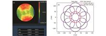
The CGH main area is to calibrate the pose and system error of the optical wedge test system, which uses +1 as the main diffraction order. The design residual is shown in Fig. 5(a). As can be seen, the residual RMS is 1.77×10⁻⁵λ, thereby meeting the design requirements. The diffraction energy level distribution of the multi-configuration is shown in Fig. 5(b). The distance between the +1st and 0th order diffraction spots is greater than 200 μm, meeting the requirement that the main diffraction order must be completely separated from the others. The diffraction pattern and setting parameter are shown in Fig.5(c) and Fig.5(b). The stripe line width is calculated using empirical equation (3):
where Daperture is the aperture of the CGH′s main area, ncf is equal to the value of the contour format and N represents the number of stripes. In this case, Daperture=119.52 mm, ncf=1000, N=19 and the stripe line width of the main area lmain=3 μm. This value meets the requirements of conventional CGH processing technology and can be processed and produced by laser direct writing and ion beam etching.
![]()
Figure 5.Main area of the CGH. (a) Design residual; (b) diffraction order energy level distribution; (c) diffraction pattern; (d) surface phase setting parameters
3.2 Alignment area design
The CGH alignment area is used to align the relative position between the interferometer and the CGH, which used +3 as the main diffraction order. Fig 6 shows that the CGH alignment area appears as the green crescent-shaped structure in Fig. 4 due to the deflection introduced by the optical wedge.
![]()
Figure 6.Schematic of the single optical wedge deflection light path
The design residual is depicted in Fig. 7(a) (Color online). The residual RMS is 8.00×10⁻⁶λ, thereby meeting the design requirements. The diffraction energy level distribution of the multi-configuration is depicted in Fig. 7(b) (Color online). The main diffraction order is completely separated from the other diffraction orders (Fig. 7(c)), eliminating the influence of the remaining diffraction orders on the main one. The width of the stripe line of the alignment area is obtained as 8 μm using Eq. (3). This also satisfies the requirements of conventional CGH processing technology and thus can be processed and produced by laser direct writing and ion beam etching.
![]()
Figure 7.Alignment area. (a) Design residual; (b) diffraction order energy level distribution; (c) diffraction pattern
3.3 CGH error analysis
An amplitude-type CGH is used in this study. When calculating CGH error sources, the main considerations are design residuals, coding errors, substrate errors and characteristic distortion[
![]()
Figure 8.Substrate error
The test accuracy of single optical wedge compensation under CGH calibration is also analysed. The random noise in Table 5 can be obtained by averaging multiple measurements. Fig. 9 (Color online) shows the test results of a convex spherical surface with a diameter of 197 mm using the stitching algorithm in this paper. From Fig. 9(d), the stitching algorithm can be obtained as 0.002λRMS (1.26 nm). As presented in Table 5, the analysis showed that the accuracy of the single optical wedge compensation test after CGH calibration is 3.43 nm RMS, thereby meeting the requirements of calibrating large convex aspheric surfaces. The results showed that CGH can be used to calibrate the pose and system error of a single optical wedge compensator and to improve the accuracy and reliability of the single optical wedge compensation test method.
Table 4. CGH error
Table 4. CGH error
Error type Value design residual 1.77×10⁻⁵λ coding error 9.00×10⁻⁴λ substrate error 3.00×10⁻³λ characterization distortion 1.57×10⁻⁴λ RMS 3.10×10⁻³λ
Table 5. Single optical wedge compensation test accuracy after CGH calibration
(nm) Table 5. Single optical wedge compensation test accuracy after CGH calibration
(nm) Error Value Measuring random error 2.5 CGH calibration test optical path system error 1.98 Accuracy of stitching algorithm 1.26 RMS 3.43
![]()
Figure 9.Convex spherical stitching test result (
4 CGH calibration test system′s error
After analysis, the CGH is used to calibrate the actual single optical wedge compensation test optical path. The test optical path is depicted in Fig. 10. Firstly, the position of CGH on the turntable was determinated. The mark in the X direction on the CGH was parallel to the X direction of the turntable, and the mark in the Y direction on the CGH was coincide with the Y axis of the turntable. Then, the CGH along the Y axis was moved to the design position.
![]()
Figure 10.(a) Calibration optical path diagram of optical wedge compensator. (b) CGH and interferometer aligned on the optical path. (c) Insertion of the optical wedge compensator
After the CGH position was determined, the CGH alignment area was used to align the position between the interferometer and CGH, as depicted in Fig. 9(b). The alignment area test results are shown in Fig. 10(a) and Fig. 10(c). Eq(4) is used to calculate the defocus εz between the CGH and interferometer on the Z-axis to determine whether the alignment between the interferometer and the CGH is complete. Here, F#=13 and ΔWdefocus represent the Peak-to-Valley(PV) in the test result. Taking Fig. 10(a) as an example, the defocus εz between the focal point of the CGH and the focal point of the interferometer is obtained as εz=0.056 mm. This distance meets the adjustment requirement of the test mirror; therefore, the alignment between the interferometer and the CGH was complete.
After alignment, we calibrated the single wedge compensator, as shown in Fig. 11 (Color online). The calibration error results of Tap#2 (Fig. 11(b)), and Tap#2 (Fig. 11(d)) are 0.023λRMS and 0.011λRMS, respectively. When the single optical wedge stitching is used to test the full-aperture surface, the system error obtained by calibration can be eliminated. Therefore, the accuracy and credibility of the single optical wedge compensation test is improved.
![]()
Figure 11.Calibration results for the test path system error. (a) CGH alignment result by Tap#2. (b) Test path system error by Tap#2. (c) CGH alignment result by Tap#3. (d) Test path system error by Tap#3
5 Conclusion
A method that uses reflective CGH calibration for a single optical wedge error test compensation system is proposed. The method decouples the errors in the test results of single optical wedge compensation. The feasibility of the method is verified through analysis of the CGH principle, fringe contrast, and the sensitivity of the single wedge compensator in testing and adjusting the optical path.
In addition, a reflective CGH calibration experiment is designed for the single optical wedge test optical path to test large convex aspheric mirrors with a diameter of 425 mm. The CGH calibration accuracy is 1.98 nmRMS. After CGH calibration, the test accuracy of the full surface of single wedge compensation is 3.43 nmRMS, thereby meeting the calibration requirements of single optical test optical paths for system errors. We also obtained systematic errors at two Tap of 0.023λ and 0.011λ after CGH calibration.
The analysis and experimental results show that the reflective CGH calibration method can accurately calibrate the single optical wedge compensation test path, including both the system error and pose, thereby improving the test accuracy and credibility of the single optical wedge compensation method.
[1] LI F ZH, ZHENG L G, YAN F, et al. Optical testing method and its experiment on freeform surface with computer-generated hologram[J]. Infrared and Laser Engineering, 41, 1052-1056(2012).
[2] REN J F, GUO P J. Design of original structure of illuminating system in off-axis convex aspherical lens testing system with computer-generated hologram[J]. Acta Optica Sinica, 32, 0222005(2012).
[3] WANG X K, WANG L H, DENG W J, et al. Measurement of large aspheric mirrors by non-null testing[J]. Optics and Precision Engineering, 19, 520-528(2011).
[4] ZHANG L, TIAN CH, LIU D, et al. Non-null annular subaperture stitching interferometry for steep aspheric measurement[J]. Applied Optics, 53, 5755-5762(2014).
[5] ZHANG L, LI D, LIU Y, et al. Validation of simultaneous reverse optimization reconstruction algorithm in a practical circular subaperture stitching interferometer[J]. Optics Communications, 403, 41-49(2017).
[6] SUPRANOWITZ C, MCFEE C, MURPHY P. Asphere metrology using variable optical null technology[J]. Proceedings of SPIE, 8416, 841604(2012).
[7] CAI ZH H, WANG X K, HU H X, et al. Testing large convex aspheres using a single wedge compensation and stitching method[J]. Optics Communications, 480, 126484(2021).
[8] TRICARD M, KULAWIEC A, BAUER M, et al. Subaperture stitching interferometry of high-departure aspheres by incorporating a variable optical null[J]. CIRP Annals, 59, 547-550(2010).
[9] HE Y W, HOU X, WU F, et al. Analysis of spurious diffraction orders of computer-generated hologram in symmetric aspheric metrology[J]. Optics Express, 25, 20556-20572(2017).
[10] ZHANG H D, WANG X K, XUE D L, et al. Modified surface testing method for large convex aspheric surfaces based on diffraction optics[J]. Applied Optics, 56, 9398-9405(2017).
[11] BURGE J H, KOT L B, MARTIN H M, et al. Design and analysis for interferometric measurements of the GMT primary mirror segments[J]. Proceedings of SPIE, 6273, 62730M(2006).
[12] ZHOU P, BURGE J H. Fabrication error analysis and experimental demonstration for computer-generated holograms[J]. Applied Optics, 46, 657-663(2007).
[13] ZHAO CH Y, BURGE J H. Optical testing with computer generated holograms: comprehensive error analysis[J]. Proceedings of SPIE, 8838, 88380H(2013).
[14] BURGE J H. Null test for null correctors: error analysis[J]. Proceedings of SPIE, 1993, 86-97(1993).
[15] ZHANG H D, WANG X K, XUE D L, et al. Surface testing method for ultra-large convex aspheric surfaces[J]. Chinese Optics, 12, 1147-1154(2019).
[16] LI M, LUO X, XUE D L, et al. Design of CGH for testing large off-axis asphere by considering mapping distortion[J]. Optics and Precision Engineering, 23, 1246-1253(2015).
[17] ZHU D Y, LI M, XUE D L, et al. Absolute testing of null lens errors with tilted computer-generated-hologram[J]. Acta Optica Sinica, 35, 0412001(2015).
[18] CHEN Q, WU F, YUAN J H, et al. Certification of compensator by computer-generated hologram[J]. Acta Optica Sinica, 27, 2175-2178(2007).
[19] [19] LI M, ZHANG X J. Test of large offaxis aspheric surface with CGH[C]. CIOMPOSA Summer Session on Optical Engineering, Design Manufacturing, Optical Society of America. 2013.
[20] BURGE J H, ZHAO CH Y, DUBIN M. Measurement of aspheric mirror segments using Fizeau interferometry with CGH correction[J]. Proceedings of SPIE, 7739, 773902(2010).
Get Citation
Copy Citation Text
Zhi-hua CAI, Xiao-kun WANG, Hai-xiang HU, Qiang CHENG, Ruo-qiu WANG, Hai-dong ZHANG. Calibration of single optical wedge compensation test system error by computer generation hologram[J]. Chinese Optics, 2022, 15(1): 90
Category: Original Article
Received: Mar. 2, 2021
Accepted: --
Published Online: Jul. 27, 2022
The Author Email: Xiao-kun WANG (jimwxk@sohu.com), Hai-xiang HU (hhx@ciomp.ac.cn)
