


 View fulltext

2024
Volume: 53 Issue 12
22 Article(s)

Feng ZHU, Junzhe LIANG, Jin LIANG, Zhihui WU, Yun WANG, and Maodong REN
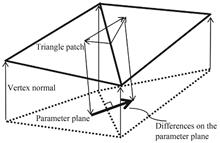
In the process of additive repair,the point cloud data obtained by scanning the workpiece with structured light is usually encapsulated into a triangular mesh. Due to interference in the scanning environment or blurring of sharp features during point cloud post-processing,the sharp features that originally existed in the workpiece will be lost,making it impossible to restore the true appearance of the workpiece in the final triangular mesh. To solve this problem,this paper designs an algorithm for reconstructing sharp features in triangular meshes and studies the detection and reconstruction techniques of sharp features in triangular meshes. Firstly,the angle between the normal vector direction of each triangular patch and the normal vector direction of its neighboring faces is detected. The selected neighboring face is a ring of neighboring faces of the triangular patch,that is,the triangular patch has common edges or vertices with these neighboring faces. If there is an angle exceeding a certain threshold between the normal vector of the patch and the normal vector of the neighboring face,the triangular patch is set as a feature patch,and the feature patch is recorded and saved in a set. Next,traverse each feature patch in the set,determine whether it is the outermost feature patch,that is,whether it is adjacent to a non feature surface. If it is adjacent to a non feature surface,enter the processing step for that feature patch,find its similar patch in the non feature patches in its neighborhood,and adjust the normal vector direction of this feature patch according to the normal vector direction of the similar patch,so that the normal vector direction of this feature patch is as parallel as possible to the normal vector direction of the similar patch. Then,continue to adjust the positions of the three vertices of the feature patch,adjust the vertex positions of the feature patch according to the direction of the normal vector adjusted in the previous step,so that the adjusted triangular patch is as perpendicular as possible to the adjusted normal vector. Before adjusting each vertex,it is necessary to determine whether the vertex also belongs to a non feature surface. If the vertex also belongs to a non feature surface,the vertex position will not be adjusted. After all three vertex positions of the feature patch are adjusted,continue to traverse other unprocessed feature patches in the set. Finally,set the feature patches that have undergone the above processing as non feature patches,and repeat all the above steps until the normal vector directions and vertex positions of all feature patches are processed. All the above steps can be repeated multiple times,and after a certain number of iterations,the Laplacian denoising step can be performed to achieve better sharpening effect. The experimental results show that the running time of sharpening increases with the increase of the number of facets,and is also related to the shape of the triangular mesh model. The more feature facets there are,the longer the processing time is. The proposed sharpening method has a sharpening time of less than 10 s for processing 100 000 triangular facets. The proposed sharpening method has a relatively stable effect on triangular meshes with different densities,but the sharpening effect on overly sparse triangular meshes is poor. The sharpening effect on triangular meshes is not entirely determined by the complexity of the model's shape,but mainly depends on the sparsity degree of the triangular meshes. The proposed sharpening method can effectively sharpen triangular meshes with a large amount of noise and basically meets the requirement of reconstructing sharp features that have already been lost.
Dec. 25, 2024Vol. 53 Issue 12 1210001 (2024)
Yifeng LI, Shun ZHOU, Pangyue LI, Huachen LIU, Xinyan ZHENG, Jin CHENG, Xueping SUN, and Weiguo LIU
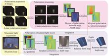
Traditional three-dimensional imaging methods can be categorized into active imaging and passive imaging based on the presence of illumination sources. Structured light technology,as a form of active imaging,does not perform satisfactorily in imaging surfaces of objects without texture or lacking texture. Passive polarized three-dimensional imaging technology offers an effective imaging method for such objects,yet it still encounters challenges related to sensitivity to noise and ambiguity in reconstruction. In response to the limitations of a single mode,this study proposes a three-dimensional reconstruction method that combines active structured light with passive polarization.The initial step in obtaining polarised images is to rotate a polariser to capture different polarisation states. Subsequently,the images are subjected to denoising and the calculation of polarization degree,polarization angle,and zenith angle,to reduce noise's impact on polarization information significantly. This results in an ambiguous azimuth angle. To address this ambiguity,structured light is employed to obtain a point cloud and depth images of the object under examination. The gradient information of the depth image in this state is obtained and used to rectify the polarization gradient information derived from the polarization information,thus eliminating ambiguities caused by the polarization angle. Subsequently,the corrected gradient information is integrated to obtain a rough relative depth map of the object,which exhibits surface roughness at this stage. To address this,the mesh data extracted from the obtained rough relative depth map is subjected to smoothing,thereby acquiring a smooth relative depth map. Finally,the fused absolute depth map of the object is obtained by combining the original point cloud from structured light with Poisson reconstruction.In this study,key points on the measured object were randomly selected and the actual physical distances between these points were compared with the distances computed by the reconstruction model. The absolute error between the calculated and measured distances was less than 0.6 mm. The relative error is less than 3%,verifying the algorithms' validity. It can be seen that the polarization active-passive fusion 3D reconstruction technique based on structured light,as proposed in this paper,not only achieves a high standard of accuracy but also shows high reliability. The application of this method provides an effective technical means for accurate 3D reconstruction of textureless objects.
Dec. 25, 2024Vol. 53 Issue 12 1210002 (2024)
Meitu YE, Meilin XIE, Min GUO, Heng SHI, Yan TIAN, Wei HAO, Lu DING, and Guangyuan TIAN
In recent years,hybrid solid-state LiDAR has gained widespread application across aerospace,autonomous driving,and UAV remote sensing due to its reasonable cost and advanced manufacturing technology. Despite its advantages in portability and long-range detection capabilities,many researchers overlook the inherent challenges such as systematic errors,random interference,and instability issues,particularly the “edge tailing” effect within the near-field range of tens of meters. This phenomenon significantly impairs the reliability of close-range detection and testing tasks. This article begins by outlining the fundamental 3D imaging principles of solid-state LiDAR and discusses the unpredictability of near-field detection errors. It introduces a method for analyzing a measured target's 3D point cloud data using the Oriented Bounding Box (OBB) algorithm,establishing a framework for subsequent data acquisition and analysis. Experimental statistical methods were then employed to quantitatively analyze the measurement results,elucidating the influence of systematic “edge tailing” on the direct fitting results of spheres. This study also identifies a variance in echo intensity between the tailing and central points. Leveraging the existing discovery,an automatic denoising method was devised to eliminate noise from the tailing point clouds,thereby reducing systematic errors. Moreover,the analysis reveals that measurement distance,target surface colour,and motion speed significantly contribute to random errors. Recommendations are made for optimizing working distance,target colour,and flight speed in near-field detection to minimize these errors and enhance measurement stability. A series of experiments were conducted to verify the effectiveness of these methods,measuring the attitude of a large angular velocity rotating target at a 30-meter range. Identification of “expansive” trailing points at the target edges,is enabling the establishment of a precise cutoff threshold for their filtering,meaning that optimal working distances enhance the accuracy of tracking and measuring cooperative targets,with white being the preferred target colour for both day and night conditions. The necessity of defining the dynamic speed limit of the target to select a LiDAR with an appropriate frame rate,minimizes significant accuracy losses. For laser LiDAR systems with a nominal accuracy of ±2 cm,the comprehensive error reduction methods proposed can maintain size measurements of rotating targets within ±3 cm at a 30 m near-field range. The conclusions of this study offer valuable guidelines for the application of hybrid solid-state LiDAR in the tracking and rendezvous of far-field and large targets.
Dec. 25, 2024Vol. 53 Issue 12 1212001 (2024)
Tuo REN, Pengcheng YANG, Xiaocheng LI, Enze DOU, and Xindong ZHU
With the advantages of high efficiency,high precision and non-destructiveness,laser interferometry has been widely used in the measurement of surface topography errors of objects. Surface morphology quality is an important indicator of gear manufacturing accuracy,and its micron-level,or even submicron-level error will also directly affect the stress distribution on the surface contact surface of the parts and transmission performance,not only the overall performance of the equipment,but also related to the length of service life. During the measurement process,the quality of the interferometric image,as the key data information collected,has a direct impact on the measurement accuracy. Laser interference is an effective method to measure the geometrical error of helical gear teeth,and the quality of the interference image,as the raw data collected in the measurement,directly affects the final measurement accuracy. In the measurement,the precise clamping position of the measured gear directly determines the information integrity and processability of the acquired interference image,which is one of the prerequisites and key conditions for full-area,high-precision measurement of the tooth flank. The article proposes a data-driven gear clamping error correction method in order to obtain high-quality interferometric images. First,the data-driven dataset is constructed by collecting measured and simulated data; secondly,one-dimensional calibration points were calculated in the direction of shaft inclination to derive the trend of geometric distortion index with clamping position and predict the direction of clamping error; then,the masking ratio in the measured tooth interference image is used as a bridge to establish the mapping relationship between the measured and simulated interference images,and the optimal inclination approximation is used to calculate the adjustment angle; finally,the rationality of adjustment is verified according to the distortion law. Relevant experiments were designed,and the results showed that the adjusted interferometric image occlusion ratio was reduced by 4.87%,the calibration accuracy of the PSD scale was 1,and the mean PSD value was improved by 0.27. The quality of the interferometric image can be significantly improved after adjustment by this method,and the feasibility and correctness of this method are verified at the same time. The effective improvement of the stripe quality of the interferometric image provides technical support and means of realization for the improvement of the measurement accuracy of the interferometric image.
Dec. 25, 2024Vol. 53 Issue 12 1212002 (2024)
Junjie CHEN, Junchao GAO, Junjie ZHOU, Liuxian YE, Bin WU, Bing CHENG, Helin WANG, Xiaolong WANG, and Qiang LIN
The quantum gravimeter has high requirements on the stability of laser frequency when it works in ship-borne,air-borne,space-borne and other external fields. However,due to changes in the external environment and its own instability factors,the center frequency of the laser output will change with time to produce MHz or even GHz magnitude drift,which will cause the laser mode hopping and affect the normal operation of the instrument. Therefore,it is necessary to lock the output frequency of the laser to suppress the frequency drift. The traditional laser frequency locking system needs to manually adjust the working parameters and judge the locking situation,which cannot meet the requirements of long-term stable operation of quantum precision measuring instruments without manual intervention. In this paper,a set of laser absolute frequency automatic locking system is designed by using the advantages of modulation transfer spectroscopy,such as flat zero background signal,large slope of error signal,high frequency stability (above 10-8 order of magnitude),small frequency line drift and easy locking. Firstly,based on the semiconductor laser,a frequency-locked optical path suitable for modulation transfer spectroscopy is built,and the 16-bit analog-to-digital converter is used to read the modulation transfer spectroscopy signal at high speed and send it to the automatic frequency locking operation system. The core of the laser automatic frequency locking operation system is the automatic frequency locking state machine,which contains six states: initialization state,scanning state,similarity recognition state,locking state,monitoring state and waiting for locking state. After the automatic frequency locking process is turned on,the convolution peak-seeking algorithm is used in the state machine to find the required characteristic spectrum information and obtain the reference voltage signal of the frequency point to be locked,and then the reference voltage signal is sent to the laser to be locked through the feedback control unit. Finally,the automatic locking of the laser frequency and the fast locking after the unlocking are realized. The test results show that after the system opens the automatic frequency locking process,the frequency ten thousand level stability is increased from 6.672×10⁻⁸@8 000 s in the free running state to 1.265×10⁻¹¹@8 000 s in the frequency locking state,which is increased by three orders of magnitude. When the external factors cause the output frequency of the laser to be unlocked,the laser automatic frequency locking system can realize the fast relocking of the laser frequency within 1 s,and the consistency before and after the unlocking is good,and the frequency stability after the relocking reaches 6.651×10⁻¹¹@1 s. The laser automatic frequency locking system developed in this paper has the advantages of high frequency locking accuracy,short locking time,simple structure and strong stability. It can meet the needs of laser frequency locking for a long time in an unattended environment. It is appropriate for cold atom gravimeter,cold atom gradient meter,cold atom gyroscope and cold atom clock and other quantum precision measuring instruments. Because the system needs to intercept the required characteristic spectrum and mark the frequency point to be locked before the state machine opens the automatic frequency locking process,it will increase the labor cost and time cost. It is hoped that the laser automatic frequency locking scheme based on artificial intelligence algorithms can be designed in the future. The neural network can be used to automatically identify the characteristic spectrum signal and locate the frequency point to be locked,completely realizing the laser automatic frequency locking under unmanned conditions.
Dec. 25, 2024Vol. 53 Issue 12 1214001 (2024)
Qiran XIE, Yongqi LI, and Shun WU
High repetition rate optical frequency combs,characterized by short pulse intervals (<1 ns) and large longitudinal mode spacing (> 1 GHz),are crucial for precision measurements in fields such as gas detection,astronomical spectrograph calibration,and high-capacity optical communication networks. However,due to the limitations of cavity length,it is challenging to achieve GHz repetition rates with fiber-based optical frequency combs. This paper is dedicated to enhancing the repetition rate of all-fiber optical frequency combs in the 1.5 μm wavelength band.Firstly,the parameters of the Fabry-Pérot cavity and their impact on filtering performance,as well as their applicability to filtering free-running comb sources,were analyzed in detail from a theoretical perspective. Based on the principle of mode filtering of optical frequency combs,a mathematical model was established in MATLAB to numerically simulate the effects of cavity parameters such as cavity length,mirror reflectivity,and mirror curvature radius on cavity linewidth and side mode suppression ratio. The theoretical simulation results indicate that an optimized filter cavity design requires the cavity linewidth to be greater than the comb linewidth and to have an appropriate tolerance range for the locking system. Therefore,a compromise design is chosen between the locking tolerance range and side mode suppression ratio,appropriately reducing the side mode suppression ratio to cope with the frequency drift of free-running lasers,which is the starting point for the experimental design of mode filtering. Subsequently,the optical frequency comb mode filtering scheme was numerically simulated,avoiding the adverse effects of cavity design that could lead to high-order modes coinciding with optical frequency comb modes,thereby significantly reducing the side mode suppression ratio after filtering.Based on theoretical simulations,this paper designed and constructed a mode filter cavity with a cavity linewidth of 14 MHz (70 times the comb linewidth) and a cavity mirror reflectivity of 97%. Then,based on the electro-optic modulation Pound-Drever-Hall technique,an experiment was conducted to filter the modes of a fully fiber-locked laser oscillator with a repetition rate of 97.4 MHz. This achieved a significant increase in the optical frequency comb repetition rate from 97.4 MHz to 1.75 GHz and 1.65 GHz,with a minimum side mode suppression of 23 dB. The frequency uncertainty of the stabilized comb was 0.99 MHz,successfully addressing the frequency drift of free-running fiber combs. Based on the experiments,the paper further theoretically proved that the designed mode filter cavity can filter most single-cavity dual-comb systems. Finally,this paper conducted four sets of comparative experiments to study the effects of cavity higher-order modes and the original repetition frequency of the optical comb on filtering performance. The experiments showed that when higher-order cavity modes overlap with the desired suppressed comb modes,the suppressed modes will leak out and reduce the local side mode suppression ratio. Additionally,the higher the original repetition frequency of the optical comb,the higher the side mode suppression ratio that can be achieved. In addition to the above analysis,a method was also discovered to further increase the repetition rate based on the cavity free spectral range. For example,by selecting a cavity length that matches every other cavity fundamental mode with a comb tooth,the repetition rate of the filtered comb is twice the cavity free spectral range. This method is an effective way to obtain a high repetition rate optical frequency comb through a simpler mode filter cavity structure.The experiment in this paper successfully achieved a GHz repetition rate locked femtosecond laser. The above exploration may further realize a higher signal-to-noise ratio and more portable GHz fiber optical frequency combs.
Dec. 25, 2024Vol. 53 Issue 12 1214002 (2024)

Yufeng TONG, Shijie ZENG, Hongwang YANG, Cai WEN, Jinlong TANG, Min CHEN, Xiaoyu LI, Zhuang XU, Yuan WEI, and Yong REN
Mixed oxides are extensively utilized in the solar cell development due to their beneficial properties. For instance,MgO is commonly incorporated into electron transport layers that shows significant carrier recombination,helping to suppress this recombination and enhance the Photoelectric Conversion Efficiency (PCE). Furthermore,ZnO finds the widespread application in sensors and various types of solar cells. In silicon-based solar cells,ZnO nanostructures can enhance the absorption of the blue-ultraviolet spectra,thereby improving their fill factor and PCE. However,the oxygen vacancies (Vo0,Vo+,Vo2+) in ZnO can create recombination centers,negatively affecting its n-type semiconductor properties. Therefore,addressing these defect-induced recombination centers is crucial.This study investigated the incorporation of MgO nanoparticles into ZnO to create a homogeneous mixture. The mixed powder was dispersed in an ethanol solution and subjected to the ultrasonic agitation,resulting in a uniform suspension of the nanoparticles. After adding a small amount of thickening agent,the suspension was spin-coated onto the emitter surface of a p-type Passivated Emitter and Rear Cell (PERC). The nanoparticle coating was then solidified through a high-temperature annealing. To ensure a direct contact between the nanoparticle coating and the emitter,a “semi-finished” PERC cell without a front-side SiNx layer was used as the substrate. This semi-finished cell has a slightly lower PCE of approximately 17.1% compared to the fully finished cells. During the film preparation process,the electrical properties of the mixed nanoparticle coating were optimized using the control variable method. Variables such as the ratio of mixed nanoparticles,the concentration and viscosity of nanoparticles in the spin-coating solution,the spin-coating speed,and the curing temperature were adjusted to address the issue of poor electrical stability in the nanoparticle coating.The current-voltage curves of the solar cell samples,measured before and after applying the coating,revealed that substrate cells with the ZnO-MgO nanoparticle coating exhibited a higher short-circuit current density under illumination. Additionally,the ZnO-MgO nanoparticle coating increased the overall PCE of the solar cell from 17.10% to 19.22%,representing a 4.68% improvement compared to the PCE of the use of ZnO nanoparticles alone (18.42%). This indicates that the ZnO-MgO nanoparticle coating provides a superior enhancement in the electrical performance of the solar cells. The Hall effect measurements further showed that the ZnO-MgO nanoparticle coating resulted in a higher carrier concentration and a slower decay of photogenerated current after the light exposure,suggesting that the carrier recombination processes were effectively suppressed. The nano-spherical morphology of ZnO-MgO nanoparticle coating on the textured emitter surface also exhibited light-trapping effects,further enhancing the light absorption and improving the PCE. Furthermore,the excitation spectrum analysis indicated that the addition of MgO nanoparticles facilitated the electron transport and reduced the recombination speed within the ZnO nanoparticle coating,significantly lowering the peak intensity of the excitation spectrum.From a structural perspective,the microstructure of the ZnO-MgO nanoparticle coating exhibits a light-trapping capability,forming a layer of spherical particles ranging from 30 to 70 nm in diameter on the solar cell emitter surface. This layer enhances the light absorption capacity of the substrate solar cell,particularly in the ultraviolet and visible spectra regions,due to the combined contributions of ZnO and the substrate. Additionally,the incorporation of MgO effectively suppresses the charge recombination,leading to the enhanced optical and electrical performance of the solar cells. Thus,the use of ZnO nanoparticles alone resulted in a 1.32% increase in the PCE,whereas the combined effect of ZnO and MgO nanoparticles yielded a 2.12% PCE improvement compared to that of the substrate. These results demonstrate that the ZnO-MgO nanoparticle coating not only optimizes the light absorption and the carrier concentration,but also reduces the carrier recombination,thereby meeting the solar cell's requirements for the enhancement in minority carrier lifetime. This research provides new insights and potential applications for the development of next-generation solar cells.
Dec. 25, 2024Vol. 53 Issue 12 1225001 (2024)
Zijian WANG, Huiling ZUO, Meng WANG, Chenglin WANG, and Haiyan NAN
This study aims to improve the performance of MoTe?/MoS? heterostructure-based optoelectronic devices by utilizing surface engineering techniques,specifically organic molecule doping and annealing. The focus is on optimizing the electronic properties of these heterostructures to enhance their optoelectronic performance,making them more suitable for applications in various photodetectors and other optoelectronic devices. MoTe? and MoS? thin layers were prepared using mechanical exfoliation,ensuring high-quality samples. The MoTe?/MoS? heterostructures were then fabricated using a dry transfer method. To improve the properties of the heterostructures,the samples were doped with organic molecules,including 2,3,5,6-tetrafluoro-7,7,8,8-tetracyanoquinodimethane (F4-TCNQ) and rhodamine 6 G (R6G). After doping,the samples underwent an annealing process to further optimize their electronic properties. These devices were characterized using Keithley instruments for current-voltage measurements and photocurrent testing,while structural and morphological observations were carried out with a Leica DM2700 optical microscope. The performance of the devices was analyzed under different bias and illumination conditions to assess the effects of surface engineering on their optoelectronic properties. The experimental results revealed that the surface-engineered MoTe?/MoS? heterostructures exhibited significant improvements in their optoelectronic performance. Under a -2 V bias and 637 nm illumination,the photocurrent increased substantially from 8.23×10⁻⁸ A at zero bias to 7.12×10⁻⁷ A,while the photoresponse time decreased from 4.12×10⁻⁸ s to 7.49×10⁻⁹ s. These improvements correspond to a significant increase in sensitivity,conversion efficiency,and response speed,indicating that surface engineering,including organic molecule doping,plays a critical role in enhancing the performance of MoTe?/MoS? heterostructure-based optoelectronic devices. Among the doping agents tested,F4-TCNQ was found to be particularly effective,as it significantly modified the electronic structure of MoS?,contributing to the formation of a potential barrier at the MoTe?/MoS? interface. This barrier,resulting from the difference in Fermi levels between MoTe? and MoS?,induced band bending at the heterojunction interface,which played a crucial role in improving carrier transport and reducing recombination losses of charge carriers,leading to better device performance. The photoresponse characteristics of the device also exhibited significant improvement after doping. Due to the material thickness and the risk of device breakdown under prolonged high-power illumination,the experiments were conducted within a power range of 57.67 μW to 207.1 μW. Compared to the intrinsic MoTe?/MoS? heterostructure's photoresponse time under zero bias,the doped MoTe?/MoS? device with a coplanar electrode structure demonstrated a reduction in photoresponse time from 2.27×10⁻⁴ s to 1.42×10⁻⁴ s under illumination at λ=637 nm with an incident power of 18.94 μW. Additionally,a power-dependent response was observed,indicating the existence of an optimal power level at which the photodetector achieved peak response speed,likely due to saturation effects. When the incident power exceeded a certain threshold,the photodetector entered a saturation state,although the exact threshold power range could only be approximately estimated due to the precision limitations of the measurement equipment. These findings emphasize the importance of considering power factors in the design of optoelectronic devices to balance photo response time and rectification ratio. On the other hand,R6G doping had a relatively smaller effect on improving performance compared to F4-TCNQ,likely due to its weaker electron-withdrawing properties. In addition,to study the effect of surface treatment on the MoTe?/MoS? heterostructure photodetector,annealing treatment was applied to the heterostructure devices. This helped reduce defect density and improve the crystallinity of the MoTe? and MoS? layers,further enhance carrier mobility and overall device performance. Although no significant adsorption of organic molecules on the lower MoTe? layer was observed,the effect of F4-TCNQ doping was still evident,likely because it can alter the electronic properties of the entire heterostructure. The above experiments have demonstrated that surface engineering through organic molecule doping and annealing treatment is an effective method for enhancing the performance of MoTe?/MoS? heterostructure optoelectronic devices. Among the organic molecules tested,F4-TCNQ showed the most pronounced effects,resulting in significant improvements in carrier transport,photocurrent,and response time. These findings highlight the potential of surface engineering in optimizing the functionality of optoelectronic devices made from 2D materials and provide valuable insights for the design and fabrication of high-performance optoelectronic systems.
Dec. 25, 2024Vol. 53 Issue 12 1225002 (2024)
Tao YANG, Wei YAN, Huimin ZHANG, Zhixiang WU, Yunjing JI, Yan ZHAO, Jiancheng LAI, Chunyong WANG, and Zhenhua LI
With the continuous development and advancement of intelligent transportation systems,autonomous driving and assisted driving technologies are increasingly maturing. Lidar has emerged as one of the key sensor components in this domain. Lidar is an optical sensor that detects target information from scattered light,where the scattering characteristics of the target significantly influence its detection performance. In the realm of smart driving,vehicles can extract surface features of the pavement from the scattering characteristics of the environment,thus enabling the detection and analysis of road conditions. A critical aspect of studying pavement scattering characteristics involves developing an accurate and efficient computational model for the scattering process. Early research by foreign scholars has yielded a series of classic methods for rough surface scattering processes. More recently,some domestic scholars have introduced partial scattering models to enhance the calculations of pavement scattering characteristics. However,traditional computational methods are typically applicable to radar bands in remote sensing scenarios and come with stringent application conditions. Some numerical methods struggle with computational efficiency and accuracy when handling large-scale targets. To address these challenges,this paper introduces a geometric optics ray tracing method that integrates analytical approximations with numerical methods to model the laser scattering characteristics of water-covered pavements. This hybrid approach allows for the precise simulation of laser scattering characteristics before and after the pavement is covered with water,which can be utilized for feature extraction and road type perception. This innovative method not only enhances the modeling accuracy of laser scattering characteristics but also improves computational efficiency,making it adaptable to various application scenarios.Specifically,this paper investigates the scattering characteristics of asphalt pavement at a 905 nm wavelength when covered with water. Initially,a microstructure model of the rough asphalt surface is developed using linear filtering techniques. Subsequently,a geometric optics ray tracing method is employed to establish a computational model for light scattering from rough asphalt surfaces. Building upon this,the model is refined to account for occlusion and multiple scattering effects during the scattering process,thereby enhancing its applicability across various levels of surface roughness. Further,the model is utilized to calculate the laser scattering intensity distribution for asphalt surfaces both prior to and following water coverage. The accuracy of the model is rigorously validated through laser scattering intensity measurement experiments. Finally,the study explores the variations in scattering characteristics under different incident angles as a function of surface roughness and water cover depth.The research findings indicate that the results obtained from the model established in this study closely align with the experimental measurement results,demonstrating that the method can compute the laser scattering characteristics of asphalt pavements effectively. For dry asphalt pavements,when the incident light is at a small angle of incidence,both s-polarized (s-) and p-polarized (p-) light exhibit peaks near the specular direction; however,the peak of the s-light shifts slightly towards larger angles,while the peak of the p-light shifts towards smaller angles. As the angle of incidence increases,the s- light scattering peak moves towards the larger angle specular direction,with the leading edge of the peak becoming steeper. Meanwhile,the p-light begins to exhibit two distinct peaks,with the Brewster angle appearing at approximately 46°. When the asphalt pavement is covered with water,the water layer significantly attenuates the scattered light,reducing the scattering intensity to about one-fifth of its pre-water state. Under these conditions,the scattering intensity distribution curve of the s-light shifts to the right (towards larger angles) with increasing incident angle,but the rise rate of the leading edge of the peak is slower compared to the dry condition. For the p-light,as the angle of incidence increases,the Brewster angle disappears in the scattering intensity distribution curve.Overall,this paper focuses on common water-covered asphalt pavements and utilizes a geometric optics ray tracing method to construct a laser scattering model for such conditions. The accuracy of this model is validated through experiments. Based on this model,the study employs numerical computations to analyze the influence of factors such as surface roughness and incident light polarization state on the scattering intensity at different incident angles. The results indicate that the distribution curve of the scattering intensity gradually approaches a cosine distribution as the surface roughness increases. Additionally,when the root mean square slope exceeds 0.5,an enhanced backscattering trend emerges. There are significant differences in the scattering characteristics of asphalt pavements before and after they are covered with water. After being covered with water,the width of the scattering intensity distribution curve increases,the Brewster angle of p-light disappears,and the difference between the peaks of s-light and p-light diminishes. Furthermore,covering the asphalt with water leads to a sharp peak in scattering intensity in the mirror reflection direction of the incident light,while the intensity of the peaks outside this sharp peak decreases significantly,amounting to approximately one-fifth of the original peak value. This difference increases with the increase in the incident angle. These research findings are of significant importance for the development of environmental perception technologies in intelligent driving. They provide theoretical and experimental data support for pavement condition perception techniques and the optimization of vehicle-mounted optical sensors.
Dec. 25, 2024Vol. 53 Issue 12 1229001 (2024)
Fanji WANG, Liuyi LING, Haopeng ZHANG, and Shuo GAO
The Quartz-enhanced Photoacoustic Spectroscopy (QEPAS) technology boasts high sensitivity,rapid response,and compact size. It has emerged as one of the prominent methods for detecting atmospheric pollutants in recent years. The on-beam Quartz Tuning Fork(QTF),with its superior anti-interference capability and stronger photoacoustic coupling effect compared to off-beam quartz tuning forks,serves as the foundation for designing a on-beam quartz-enhanced photoacoustic spectroscopy system for atmospheric NO2 detection. The quartz tuning fork,adopting a T-shaped structure,reduces resonance frequency while maintaining a high quality factor,thus increasing the amplitude of the photoacoustic signal. Finite element analysis using COMSOL Multiphysics software simulates the tuning fork,revealing its first six modal shapes and resonance frequencies. The fourth vibration mode is identified as symmetrical and effective,with a simulated characteristic frequency of 12 418 Hz. Experimental calibration of the tuning fork's resonance frequency under standard atmospheric pressure yields 12 464.5 Hz with a quality factor of 12 850,indicating a relative error of 0.37% compared to the simulation model,affirming the model's validity. The acoustic detection module of the NO2 sensor features a chamber volume of only 7 cm3,offering the advantages of small size and light weight. The laser source for the NO2 quartz-enhanced photoacoustic spectroscopy sensor employs a 150 mW Xilong Optoelectronics DL~~405 semiconductor laser emitting at a wavelength of 403.56 nm with a full width at half maximum of 0.84 nm. The NO2 absorption cross-section in the central wavelength spectral region is approximately 5.948 5×10-19 cm2/molecule. The coupled power after optical coupling,measured using a Hamamatsu S1223-01 photodiode,is 45.6 mW. Experimentation optimizes the impact of gas flow rate on noise,with noise levels rapidly increasing above 80 sccm,thus selecting 60 sccm as the optimal flow rate. Evaluation of the NO2 quartz-enhanced photoacoustic spectroscopy sensor's performance across different NO2/N2 concentration mixtures,ranging from 100×10-9 to 10×10-6 NO2 levels,utilizes linear regression equations to assess sensor response,fitting NO2 concentration to photoacoustic signal values,resulting in an R-square value of 0.999. Allan variance analysis examines the long-term stability of the NO2 sensor,introducing pure N2 into the chamber,yielding a detection sensitivity of 3.09×10⁻⁹ and a corresponding normalized noise equivalent absorption coefficient of 1.32×10⁻⁸ cm-1·W·Hz-1/2 at 1 s averaging time and standard atmospheric pressure. When extending the averaging time to 434 s,the lowest detection limit is 0.32×10⁻⁹,indicating diminishing maximum NO2 concentration values and Allan variance with increasing integration time. To validate the real-time monitoring performance of the T-shaped NO2 quartz-enhanced photoacoustic spectroscopy sensor,continuous real-time monitoring is conducted for two weeks from April 4th to April 17th,2024,outside the laboratory of the School of Artificial Intelligence,Anhui University of Science and Technology,Huainan,Anhui Province,China. During the experiment,NO2 concentrations ranging from 3×10⁻⁹ to 18×10-9 are measured,with an average concentration of 8.6×10⁻⁹. The consistency between the two systems is satisfactory: the nonlinear fitting slope is 0.83±0.012,the intercept is 1.35±0.11,and the correlation coefficient is 0.87. The experimental results align closely with those of the environmental monitoring station,affirming the system's capability for ppb-level online NO2 detection and real-time monitoring of NO2 concentration fields,validating the sensor's stability and reliability.
Dec. 25, 2024Vol. 53 Issue 12 1230001 (2024)
Tianhe YANG, Jiahui HE, Jikuan ZHAO, Xinyu ZHAO, Tong WU, Jingyi ZOU, Xu JIAN, and Ke CHEN
Leakage monitoring of Gas Insulated Switchgear (GIS) is of great significance for the stable operation of power systems. SF6 is an artificially synthesized inert gas that is colorless,odorless,non-toxic,and non-flammable,with excellent stability. 80% of SF6 worldwide is used in the power industry. GIS is a closed electrical equipment,and SF6 is stored in a pressurized state within the equipment. During long-term use,problems such as decreased airtightness may occur,leading to SF6 gas leakage,affecting the insulation performance of the equipment,and causing great safety hazards. SF6 is also one of the six greenhouse gases mentioned in the Kyoto Protocol,and its greenhouse effect is tens of thousands of times that of the same volume of carbon dioxide. Leakage of SF6 gas into the external environment will exacerbate the deterioration of the greenhouse effect. The traditional SF6 gas detection methods have some problems,such as low measurement accuracy,complex operation,and short service life. To effectively meet the challenges posed by the emerging field of intelligent power systems,there is an urgent need to enhance the accuracy,reliability,and convenience of detection technologies. The application of photoacoustic spectroscopy to obtain gas concentration information is a non-radiative relaxation process and belongs to the indirect detection method of gas concentration. This paper designs a gas sensor with high sensitivity,miniaturization,and low-cost characteristics for SF6 gas leakage monitoring. The SF6 gas photoacoustic spectroscopy detection technology mainly utilizes the mid infrared band. According to the Hitran database,the absorption spectra of SF6,H2O,and CO2 in the wavelength range of 10 μm~11 μm at room temperature and atmospheric pressure were plotted. When the wavelength is 10.5 μm,SF6 has a very high absorption coefficient and there is almost no cross interference from interfering gases. The wide spectrum infrared thermal radiation light source EMIRS200 with a wavelength range of 2~14 μm was selected as the excitation light source,combined with a filter with a central wavelength of 10.5 μm and a bandwidth of 0.5 μm,effectively avoiding the absorption interference of H2O and CO2 in the air. The non-resonant photoacoustic cell adopts a diffusion inlet structure,and SF6 enters the photoacoustic cell in a free diffusion form through the micropores on the outer wall of the photoacoustic cell. The gas diffusion structure uses a breathable hole with a radius of 0.65 mm,covering a hydrophobic breathable film with a pore size of 0.2~0.5 μm. The breathable film is made of expanded polytetrafluoroethylene,which has good chemical stability,an opening rate of 80%,and a thickness of 0.3 mm. The support layer is made of polypropylene material. The breathable film can be used normally in environments ranging from -40 ℃ to 120 ℃. This structure reduces the volume of the sensor and lowers the cost. The overall dimensions of the sensor are 1.4 cm×1.5 cm×1.65 cm,and the volume of the photoacoustic cell is 0.13 mL. The sound pressure inside the non-resonant photoacoustic cell is uniformly distributed,and the microphone is embedded in the cell to receive and convert the sound wave signal into an electrical signal. The relationship between the photoacoustic cell radius and sound pressure was simulated using COMSOL Multiphysics finite element analysis software. It was found that there is a higher photoacoustic signal when the modulation frequency is low,and the photoacoustic signal increases with the decrease of the photoacoustic cell radius. However,the size of the photoacoustic signal is proportional to the incident light power,and a balance should be made between the radius and the incident light power. Therefore,the photoacoustic cell radius is designed to be 2 mm. The response time of the sensor is the time required for the photoacoustic signal value to increase from 10% to 90%. The experimental results show that the sensor has a response time of 178 seconds for SF6 detection. To test the photoacoustic response of the sensor,SF6/N2 gas mixtures of different concentrations were configured with a response degree of 14.47 μV/ppm within the concentration range of 0~100 ppm. The goodness of fit of the response curve is R2=0.997 6,photoacoustic signal response has a good linear relationship with SF6 concentration. According to the analysis of variance,when the integration time is 10 s,the detection limit of SF6 gas reaches 0.3 ppm.
Dec. 25, 2024Vol. 53 Issue 12 1230002 (2024)
Huizhe YANG, Haoran ZHANG, Jin LIU, Jing WAN, Luming ZHAO, and Yonghui LIANG
The Transport of Intensity Equation (TIE) offers an effective method for wavefront sensing,utilizing the variations in near-field defocused intensity distribution patterns across multiple propagation distances to reconstruct the phase aberrations introduced by turbulent media,such as the atmosphere. YANG Huizhe et al have explored TIE-based wavefront sensing for satellite-ground laser communication systems,addressing challenges related to the Point-Ahead Angle (PAA). Their simulations and bench experiments,using a Zernike-based linear reconstruction method,demonstrated effectiveness under high Signal-to-Noise Ratio (SNR) conditions. However,linear wavefront reconstruction faces significant nonlinear errors,rendering it ineffective in low SNR environments,which are common in low laser power scenarios typical of laser communication systems.To address these challenges,this paper proposes a Deep Neural Network (DNN) training model. The model utilizes the differences in intensity distributions observed at two distinct propagation distances as the input data. The outputs of the model are the first 4 to 79 orders of the Zernike coefficients corresponding to the phase aberrations. The input and output data used for DNN training are simulated through two processes based on the actual satellite-ground laser communication systems. The first process is the uplink propagation of a collimated laser beam through the atmospheric turbulence,while the second process is the reimaging of the backscattered patterns from these different altitudes. To generate a diverse set of datasets,three variable parameter sets are employed: the atmospheric coherence lengths of 0.05,0.10,and 0.15 meters; the turbulence layer heights of 0,5,and 10 kilometers; and the laser powers of 5,10,20,50,100,200,and 300 watts. This results in 63 unique combinations. Each combination contains 10,000 random phase screens,yielding a total of 630,000 training data. By comparing the Wavefront Errors (WFE) between the original and reconstructed phases,different model architectures,loss functions,and optimizers are evaluated. Ultimately,ResNet34 is chosen as the backbone network. A linear weight pooling method is proposed for the neck network,along with the Weighted Mean Absolute Error (WMAE) function and the SophiaG optimizer.Simulation results provide compelling evidence that the DNN approach significantly outperforms the traditional linear reconstruction methods. Notably,it substantially reduces the laser power requirements essential for effective wavefront sensing. For instance,at a laser power level of 5 W,the reconstruction accuracy achieved by the DNN model matches that of linear methods operating at a substantially higher power of 200 W. Furthermore,as the laser power exceeds 20 W,the detection error for the DNN approach stabilizes at approximately 200 nm RMS,reaching the accuracy limits of the 79th order Zernike polynomial. Moreover,the execution time is also a crucial indicator of its practicality,especially in real-time adaptive optics systems. Testing one thousand datasets on a single PC with an NVIDIA A 5 000 GPU yielded a total processing time of 0.52 seconds for the DNN,resulting in an average processing time of approximately 0.52 milliseconds per dataset,thereby meeting the real-time requirements of adaptive optics systems with a KHz sampling frequency. In contrast,under the same hardware conditions the linear reconstruction method needs approximately 27.31 milliseconds per dataset. The DNN method is about 52 times faster than the linear reconstruction method,highlighting the significant advantages of DNNs in practical applications.Although the DNN method demonstrates excellent performance in wavefront sensing accuracy and execution efficiency,it still has some shortcomings. First,the reliance on training data is a common issue for DNNs. The performance of DNNs is highly dependent on the quality and diversity of the training data. If the actual turbulent conditions differ significantly from the training data,the model's performance can decline sharply. Therefore,it is necessary to further enhance the diversity of the training data to cover a broader range of turbulent conditions and noise levels. Second,the model's interpretability is limited. DNNs are often regarded as black boxes,making their internal decision-making processes difficult to explain using physical laws. In this paper,we designed the linear weight pooling and a weighted mean absolute error loss function based on the physical context of the task. However,further efforts are required to integrate DNNs with the physical models to improve the model's interpretability and robustness.
Dec. 25, 2024Vol. 53 Issue 12 1201001 (2024)
Minxing LI, Youlong YU, Peiming WANG, and Bin LIU
As an important carrier of artificial intelligence,robots exhibit many abilities that humans do not possess. Robotic hands are an important component of robots and an important subfield of the intelligent robotics industry. Robotic hands surpass human hands in accuracy and stability. It can perform precise welding and assembly processes in the production workshop,replace humans in completing dangerous tasks such as explosive dismantling,and can also be used for deep-sea and aerospace exploration. However,traditional robotic hands are purely functional and lack the ability to perceive the surrounding environment,making it difficult to respond promptly to changes in the working environment. The application of sensor technology is a prerequisite for achieving robot control,interaction,and intelligence. The integration of sensor technology is crucial for robot control,human-machine interaction,and intelligence. Sending sensor exported data to the feedback control system improves the operational efficiency of the robotic hand. Electrical sensors have been widely used in other fields. Although the technology is mature and capable of sensing physical quantities such as force and temperature,but due to their poor flexibility,susceptibility to electromagnetic interference,difficulty in wiring,and poor flexibility,they can not fully meet the needs of intelligent sensing for robotic hands. FBG sensors use wavelength encoding,so the energy loss and electromagnetic field changes of the optical fiber can not interfere with the detection results. They also have the advantages of high accuracy,fast response speed,and low loss. FBG sensors exhibit excellent flexibility and scalability,with minimal impact on the maneuverability and agility of robotic hands. Therefore,FBG sensors are an ideal choice for sensor applications in robotic hands.In this paper,a flexible sliding sensor is proposed for detecting the sliding direction and speed of robotic hands. The sensor uses silicone rubber as the packaging material,which can improve sensitivity of the sensor and protect the FBG. Firstly,FEA was conducted using ANSYS software to obtain theoretical values of strain changes over time at different positions during the sliding process. Then,based on the simulation results of FEA,a sliding sensor was designed and the sensor fabrication was completed. Finally,a sliding detection platform was built to experimentally verify the simulation results. The experimental setup includes an FBG demodulator,sensors,PC,motor,weights,and pulleys. The motor is used to horizontally and uniformly pull weight through the surface of the sensor.The experimental results show that the sensitivity of each FBG sensor encapsulated in silicone rubber has sensitivity to pressure of 9.26,7.83 and 7.76 nm/MPa,and the sensitivity to shear force is 1.74,3.17 and 3.29 nm/MPa,respectively. When the slider slides over the sensor surface in different directions,the wavelength shift curve of each FBG shows different trends of variation. By using SVM model and 1D-CNN network to identify the sliding characteristics,the accuracy of sliding direction judgment reaches 91.0% and 93.5%,respectively. The sliding time of the slider is obtained from the wavelength shift curve,and the sliding speed can be obtained by dividing the sliding distance by the sliding time. The maximum relative error of sliding speed calculation is 9.29%. The research results of this paper have certain practical value for the research and promotion of robotic biomimetic skin.
Dec. 25, 2024Vol. 53 Issue 12 1206001 (2024)
Ying LIN, Yuhan TANG, Langzhe DU, Pengbai XU, and Xinyong DONG
Airflow velocity measurement is important in many fields such as meteorological monitoring and wind power generation. Currently,it is common to utilize ultrasonic,differential pressure,eddy current,or heat transfer methods for measuring. However,in some extreme environments,these measurements may be encounter interference,resulting in less accurate or non-functional results. Fiber optic anemometers have attracted much attention because of their advantages of electrically passive operation,resistance to electromagnetic interference,high sensitivity,integrated structure,and the ability to measure over long distances. In order to enhance the performance of fiber optic anemometers,this paper proposes a hot-wire anemometer based on fiber grating Fabry-Perot Interferometer(FPI) structure.Fiber grating FPI anemometers are prepared by sandwiching a section of cobalt-doped fiber with a length of 500 μm in the middle of two Fiber Gratings(FBGs). The cobalt-doped fiber in the interference cavity is heated with a 1 480 nm laser to form a hot wire. Due to the effect of thermal expansion and thermo-optic,the optical range difference of the FPI cavity length changes with the temperature of the cobalt-doped fiber,which brings about the wavelength redshift of the interference spectrum. As air flows through the FPI anemometer,the heat dissipation from the FPI is accelerated. The temperature of the FPI decreases,causing a blue shift in the interference spectrum,and the airflow velocity value can be calculated by measuring the change in the interference spectrum.We first performed temperature calibration experiments on the FPI anemometer probe by placing the anemometer probe in a temperature-controlled box. The output power of the broadband light source was set to 5 mW,and the output of the 1 480 nm laser was turned off to avoid the heat generated by the cobalt-doped fiber absorbing the laser. The temperature of the temperature control box was adjusted to gradually increase from -20 °C to 110°C in 10 °C steps,and the interference spectral drift of the anemometer in this temperature range was measured. Thus,the wavelength response of the FPI anemometer to temperature is obtained. The temperature sensitivity obtained by the linear fitting is 11.8 pm/°C,and the linear R2 is 0.997. To explore the impact of laser power on the initial temperature of the anemometer,we recorded the interference spectra of the FPI when the laser power was increased from 0 mW to 500 mW at a step of 10 mW. The experimental results show that the peak wavelength of the FPI interference spectrum shifts by 1.71 nm when the laser power is increased to 500 mW,which corresponds to an increase of 144.92 °C in the initial temperature of the anemometer. Finally,we carried out airflow velocity measurement experiment at different laser powers of 150,330 and 500 mW. The airflow velocity was changed from 0 to 9 m/s. The experimental results indicate that the sensitivity of the FPI anemometer increases with laser power but decreases with airflow velocity. It reached -1 053.86 pm·m-1·s at a airflow velocity of 0.1 m/s when laser power was 500 mW. It was decreased to -746.47 and -15.15 pm·m-1·s for airflow velocity of 0.5 and 5 m/s,respectively. The sensitivity of an anemometer exhibits an exponential decay trend due to Newton's law of cooling,which states that the rate of temperature decrease of a hot wire is proportional to the temperature difference between the wire and the surrounding environment. In low airflow velocity conditions,the temperature difference between the cobalt-doped optical fiber and the airflow is significant,resulting in a high rate of temperature decrease. However,as the airflow velocity increases,the temperature difference between the cobalt-doped optical fiber and the airflow sharply decreases,leading to a reduction in the sensitivity of the anemometer.The fiber grating FPI anemometer proposed in this paper has the advantages of high sensitivity,simple and compact structure,easy fabrication and low cost when compared with the previously reported optical fiber hot-wire anemometers. It is expected to be widely used for airflow velocity measurement in the related fields.
Dec. 25, 2024Vol. 53 Issue 12 1206002 (2024)
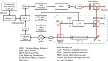
Fiber-optic Axial Strain Sensing Based on Multi-longitudinal Mode Beat Frequency with Vernier Effect
Xiaozhong TIAN, Chanchan SHEN, Jingping QIN, Xinyao FU, Heng WANG, and Lanju LIANG
With the advantages of high sensitivity,simple structure,and low cost,the multi-longitudinal mode beat frequency technique has attracted considerable attention since it was first proposed in 2010. The fundamental mechanism behind this technique is that numerous multi-longitudinal modes within the fiber laser bandwidth are stimulated and beat with each other to generate a Beat Frequency Signal (BFS). The Free Spectrum Range (FSR) of the BFS is related to the propagation time in the fiber laser cavity,thus the applied parameters on fibers can be recovered by tracking the change of selected BFS. Compared with traditional optical fiber sensors interrogated in the optical domain,the BFS can be detected in the frequency domain. Benefitting from the large frequency gap between the optical signal and frequency signal and the mature electronic instrument,the interrogation resolution and speed can be enhanced greatly. The sensitivity of BFS is proportional to the selected frequency. In other words,in order to improve the sensitivity,high-frequency BFS should be chosen,which brings instability and low measurement range.The vernier effect is an effect method to improve the sensitivity in optical fiber interferometers. The vernier envelope can be generated by combining two interference spectrums with different FSRs. Hence,the measurements can be recovered by monitoring the vernier envelope with an enhanced sensitivity. Up to now,researchers have applied the vernier effect to measure parameters,including temperature,strain,refractive index,etc. It should be noted that the vernier effect magnifies the sensitivity but also the measurement error,resulting that the vernier effect is appropriate for the applications with a damage threshold. Essentially,the vernier effect is formed by two periodic signals with different periods,it also can be generated in the frequency domain.In this paper,the vernier effect is introduced to the multi-longitudinal mode beat frequency technique to enhance the sensing sensitivity. To verify the proposed method,optic-fiber axial strain measurement is experimentally carried out. Two linear-cavity fiber lasers with different lengths are formed by a pump laser (pump),a Fiber Bragg Grating (FBG),a section of Erbium-Doped Fiber (EDF),and two Faraday reflector mirrors. With the help of the pump and the EDF,FBG-based laser with the same wavelength of the FBG is emitted and picked by a Photodetector (PD) to achieve photoelectric conversion. Benefitting from the large bandwidth of the FBG-based laser,numerous longitudinal modes are emitted and beat with each other to generate BFS,which are recorded by an Electrical Analyzer (ESA).Firstly,the axial strain sensing characteristic of cavity 2 is investigated. Breaking FRM 1 and FRM 2,the BFS with FSRs of 6.97 MHz and 7.52 MHz with signal-to-noise ratios of 20 dB are generated. Keeping FRM 2 connected and FRM 1 disconnected,a section of single mode fiber with a length of ~55 cm in cavity 2 is fixed between two move stages. The strain is applied to the fiber from 0 ~1 090.8 με with a step of 90.9 με by pulling one move stage. The BFS with the frequency of 1.506 94 GHz generated in cavity 2 is chosen as the tracking signal. Results show that with the increased axial strain,the selected BFS shifts to a lower frequency range and the slope can be calculated as -1.228 kHz/με by linear fitting test data,and the R2 value is 0.998.Secondly,the characteristic of the vernier is investigated. By connecting FRM 1 and FRM 2 at the same time,an obvious vernier effect is generated. In order to get the upper envelop curve of the BFS,extremum points are extracted and polynomial fitting is performed. The bandwidth is enhanced and the FSR is 95.06 MHz,agreeing well with theoretical analysis. Thirdly,the axial strain sensing sensitivity is experimentally tested. The strain is performed as above and the envelope with frequency of 1.524 24 GHz is selected as the tracking signal. Results indicate that the envelope shifts linearly with the increased axial strain and the sensitivity is -17.23 kHz/με with an R-square of 0.993. Compared with the sensitivity in cavity 2,the amplification is 14.09,agreeing well with the calculated value. Meanwhile,Root Mean Square (RMS) method is employed to get the frequency of the envelope,and the results shown that the sensitivity is -18.47 kHz/με,which is slightly larger with the peak sampling method.Finally,the stability in two situations is tested. In this step,the axial strain applied on fiber is kept at 90.9 με and the frequency change is recorded every 1 minute in 10 minutes. Experimental results show that the maximum frequency fluctuations are ±3.13 kHz and ±101.17 kHz,corresponding to measurement errors of ±2.55 με and ±5.74 με,respectively. It proves that the vernier not only enhances the sensitivity but also enlarges the measurement error. This study provides an important reference to enhance the sensitivity of the multi-longitudinal mode beat frequency technique and has a potential application in other parameters sensing scenes.
Dec. 25, 2024Vol. 53 Issue 12 1206003 (2024)
Bofan CHEN, Yaoke XUE, Yang SHEN, Shuifu YE, Hu WANG, and XIE Yongjie
Astronomical navigation is a navigation method which obtains attitude information of the installation platform by detecting the relative positions of stars in space. It has the significant advantages of strong anti-interference ability,high measurement accuracy,and no accumulation of errors over time,and has been widely applied. As an important device in astronomical navigation,star sensor is used to measure the relative attitude information of carrier. It uses stars as reference sources to calculate the precise attitude information of carrier by comparing with the star maps. Unlike GPS navigation signal,which is prone to rejection and accumulates inertial navigation errors over time,star sensor has several advantages,such as high precision attitude measurement ability,autonomous working ability,stable passive measurement working mode,and anti-electromagnetic interference ability. It has become one of the most necessary devices for attitude and orbit control systems on platforms such as ships,aircrafts,and satellites. Star sensor navigation technology was first applied to satellite platforms outside the atmosphere,and the dark background in outer space has a relatively small impact on the recognition of dark star targets. In recent years,with the development of all-day star sensor optical technology,astronomical/inertial integrated navigation technology has been rapidly applied to airborne platforms and near-space aircraft platforms in the atmosphere. The working altitude in the near space of 20~100 km has attracted more and more attention,and under the daytime conditions in the atmosphere,strong sky background noise caused by atmospheric scattering in the near space leads to the submergence of dark star signals. Meanwhile,the platform working in near space has strict limitations on the volume,weight,working environment,and stray light suppression ability of the system,which puts high requirements on the design of optical system for the star sensor that works in the near space. The domestic all-day star sensor optical system mostly adopts transmissive structure and catadioptric structure. The catadioptric structure mostly adopts low expansion materials,such as indium steel,fused silica,microcrystalline glass,ULE,etc. to carry out athermal design,which leads to the problems that cannot meet the requirements of lightweight design,such as large mass and volume. With the development of materials science and optical precision manufacturing technology,aluminum alloy which is a representative of metal materials can serve as both the reflector material and the supporting structural material. It has many advantages such as low density,high thermal conductivity,low processing difficulty,and short processing cycle,and has been widely used in the optical system design both domestically and internationally. This article proposes a design scheme for the lightweight star sensor optical system,by using aluminum alloy as the primary,secondary mirror material,and load-bearing structural material,in response to the requirements for lightweight,wide temperature operation,and stray light suppression of near space all-day star sensor. By analyzing the focal temperature characteristics of coaxial dual reflector system and comparing several kinds of commonly used star sensor materials,a lightweight all-day star sensor optical system was designed using a microcrystalline aluminum alloy RSA-443 as the primary reflector,secondary reflector,and support structure. The star sensor optical system has a focal length of 450 mm,an effective entrance pupil diameter of 80 mm,a field of view of 2ω=3.6°,and a working spectrum range of 0.8~1.1 μm. Adopting a passive optical athermal technology to complete the athermal design,the system has good temperature adaptation in the temperature range of -20~55 ℃. Through the design of lens hood,the Point Source Transmittance (PST) of system beyond sunlight exclusion angle of 30° is better than 10-6,which meets the requirement for high stray light suppression ratio. Compared with the design scheme of indium steel truss with fused silica or microcrystalline glass,which has low expansion coefficient,the overall mass of the system is reduced by 37%,reducing the load weight of the platform dramatically,improving the stability and durability of the system. It meets the system lightweight requirement while ensuring imaging quality,and provides effective support for the development of optical technology for all-day star sensor working in near space.
Dec. 25, 2024Vol. 53 Issue 12 1222001 (2024)
Jiangtao WANG, Hu WANG, Zhanpeng MA, Yaoke XUE, Xingyan WANG, and Jin LIAN
With the rapid development of optical technology,the application demand of high-performance optical systems in various fields is growing steadily. Especially in the fields of aerospace remote sensing,astronomical observation,scientific exploration and other fields,the performance requirements of optical systems are becoming more and more stringent. These systems are expected to have larger fields of view and broader detection bands. Reflective optical systems,which are free from chromatic aberration and can achieve large apertures while being lightweight,have garnered significant attention in satellite remote sensing. At present,in optical design,it is commonly used to find an initial structure that is similar to the design goal as a starting point for optimal design. The damping least squares method employed by optical design software in the optimization process is more sensitive to the selection of initial values. If the initial values are not selected properly,the optimization process may fail to converge or may converge to a local optimal solution,thereby failing to reach the global optimal solution. The initial structure of the off-axis reflection system is small and it is difficult to find the initial structure. Therefore,it is commonly used to design the coaxial system first and then optimize the off-axis system. To address this problem,this paper proposes a solution that combines traditional optical design with optimization algorithms. This solution makes up for the shortcoming that design software easily falls into local optimal solutions,so that the final optical system not only guarantees the global optimal solution to the greatest extent,but also has strict ray tracing calculations. Firstly,the relationship between system parameters and structural form,main mirror type,and imaging times is analyzed to provide a more reasonable range for parameter selection during the initial structure calculation process,thereby reducing the amount of calculation. Secondly,based on the aberration analysis of the coaxial three-mirror optical system,the initial structure of the system is calculated through a controlled genetic algorithm using the sum of the weighted third-order aberrations as the fitness function. Compared with the traditional Genetic Algorithm,which generally tends to have the characteristics of individuals with better fitness,the Controlled Genetic Algorithm also tends to select individuals with lower fitness values but can increase the diversity of the population,which is more conducive to the entire solution space. Find the optimal initial structure within the range. Compared with the method of directly substituting the constraints into the optimization software,the initial structure obtained by this method is more reasonable and the image quality is better. After the initial structure is determined,the aperture and field of view of the system are off-axis,and the field of view is gradually expanded while ensuring that the light is not blocked. Free-form surfaces are introduced to correct the asymmetric aberrations produced by the off-axis system. Compared with traditional spherical,the free-form surfaces have the characteristics of non-rotational symmetry and can be of any shape. They can correct the asymmetric aberration produced by the non-rotation symmetric optical system in the meridional direction,and ultimately achieve high-quality large field of view imaging. Taking an optical system with a field of view of 30°×20°,a focal length of 110 mm,an F number of 2.2,and an operating band of 3 to 5 μm as an example,the fringe Zernike polynomial is used to describe the free-form surface. Each term of the Zernike polynomial is related to aberrations have a direct correspondence. In the design process,not only can new higher-order terms be added during the optimization process to describe the free-form surface without affecting the coefficients of other terms,but terms with very small contributions can also be found to appropriately delete the design. The results indicate that the Optical Transfer Function (MTF) is near the diffraction limit and exceeds 0.6 at the Nyquist frequency of 25 lp/mm. The maximum Root Mean Square (RMS) spot radius value in the full field of view is about 6.3 μm,and the maximum distortion is less than 10%. Finally,the tolerance analysis was conducted,and under reasonable tolerance conditions,the image quality met the requirements. The effectiveness of this method in the design process of large-field off-axis three-mirror optical systems has been verified,and it has certain reference significance for the design of large-field off-axis optical systems.
Dec. 25, 2024Vol. 53 Issue 12 1222002 (2024)
Tian BAI, Feng JIANG, Lin KONG, Lei ZHANG, and Jianchao WANG
In recent years,there has been an explosive development of micro satellites,and many high-performance micro optical remote sensing satellites have been launched. Integrated design of satellite platform and payload is a method to reduce weight and improve performance. The integrated design of optical payload and platform brings great challenges to heat dissipation and high precision thermal control of optical payload. In order to ensure the imaging quality of the satellite,the temperature stability of the optical payload should be less than ±0.1 ℃ throughout the entire life cycle,and the temperature rise of CCDs is less than 1 ℃/min during imaging. Firstly,the overall layout of the satellite is presented,the orbital heat flux under different conditions has been analyzed. Due to the fact that the -Z plate of the satellite faces the cold space,the -Z plate absorbs the minimum space heat flux and has the strongest heat dissipation capacity. Therefore,the bottom plate in -Z direction is selected as the heat dissipation window for the entire satellite. Electronical components are designed reasonably to achieve temperature equalization. The maximum power of electronic components is 252 W. Reasonably set up heat dissipation channels to ensure that the temperature of electronic components will not be too high,which will affect its reliability and payload temperature stability. To realize the goal of precise temperature control for the optical payload,the calibration for the temperature sensor and measurement are proposed,ultimately enabling the temperature measurement accuracy on board to be controlled within 0.01 ℃. And the temperature control of the secondary mirror is achieved through the use of radiation heating,which makes the temperature fluctuation of the mirror less than ±0.05 ℃. Pyrolytic graphite sheets are used to improve the thermal conductivity of the optical structures by more than 10 times,creating a more uniform temperature field. The thickness of the pyrolytic graphite sheets is 1.5 mm and its thermal conductivity is 900 W/(m·K). The thermal conductivity of 10 mm carbon fiber truss can be increased from 10 W/(m·K) to 126 W/(m·K) by using the 1.5 mm pyrolytic graphite sheets. In order to reduce the temperature changes of CCDs during imaging,phase change materials and thermal straps are used inside the satellite. Thermal straps can maintain thermal contact while allowing for positional changes of focal components. The thermal resistance of thermal straps is less than 1 ℃/W. When CCDs start working,heat is first transferred to the phase change material. Phase change materials absorb heat and melt,but the temperature remains relatively constant during the process,which reduces the temperature fluctuations of CCDs. After the CCDs work,heat is transferred out through thermal straps,and the phase change material solidifies again. Then,the finite element thermal analysis model is established and the simulation calculation is completed. According to the analysis results,the temperature gradient among the mirrors and the truss is less than 1 ℃,with temperature fluctuations within ±0.1 ℃. And the temperature of the avionics is within the required range,verifying the correctness of the thermal design. Finally,the thermal balance test of the satellite was carried out and the flight data of the thermal control system has also been collected. The results of thermal test and the in orbit temperature show that the temperature of the avionics ranges from 0 to 35 ℃,the temperature of the optical payload ranges from 19.5 to 20.5 ℃,and the temperature fluctuation is within ±0.05 ℃. The CCDs temperature ranges from 15 to 20 ℃,and the temperature rise during operation is less than 0.5 ℃/min,which meets the temperature control target and imaging requirements of the satellite,and verifies that the thermal design is reasonable and feasible.
Dec. 25, 2024Vol. 53 Issue 12 1222003 (2024)
Wenbiao LIU, Bobo DU, Yigang MA, Yuantong YANG, Xiying WANG, Jinxian LU, Lei ZHANG, and Yanpeng ZHANG
With the rapid advancements in optical technologies,there are increasing demands for precise light manipulation,e.g.,beam expansions and reductions. Traditional optical components are often limited by their bulky,heavy,and expensive nature,which poses significant challenges to the system efficiency and integration. Additionally,two-dimensional metamaterials,i.e.,the metasurfaces consisting of sub-wavelength functional structures allow to manipulate optical beam with unprecedented freedoms on micro-scale chip. Upon the development of metasurfaces,a plenty of optical components were miniaturized and witnessed success in applications ranging from lenses,holography,coloration,polarization control,spectroscopy,and many more. However,the existing metasurfaces typically rely on combinations of various dielectric materials on one single chip. This feature not only leads to the complicated fabrication process but also limits their application robustness. In order to address these limitations,this study introduces an alternative approach to conduct a metalens by designing a monolithic dielectric metasurface using lithium niobate (LiNbO3,LN). LN was selected because of its extraordinary optical properties,including wide-band transparency for transmissive operations and high refractive index to localized optical field. Furthermore,beam expanders and reducers based on the monolithic dielectric metalenses were proposed and investigated numerically. The monolithic dielectric metalens was designed based on the theory of the Generalized Laws of Reflection and Refraction,in which way the phase delay of light through the LN metasurface was adjusted by altering the size of the cylindrical LN unit cell. Then,varied sizes of the LN nano-pillars were arranged according to the required phase profile to enable the metalens functionality. In detail,a series of Finite-Difference Time-Domain (FDTD) simulations were performed and the geometrical parameters of the unit cell providing required phase delay for light focusing were then optimized. The features of the proposed monolithic dielectric metalenses were evaluated in terms of focal length,spot size of the focused beam,intensity distribution,as well as the phase profiles of focused spots. The simulations confirmed the comparably excellent performances of the proposed monolithic dielectric metalens with the family of metalenses while the monolithic metasurfaces are unlike the majority of current ones with complex structures and various materials. For instance,one of the proposed monolithic dielectric metalenses has a diameter of 48 μm and an expected focal length of 96 μm. The simulated showed that a transmission efficiency of 56% and a focusing efficiency of 39% with the focused beam spot of 3 μm and the focal length of 89.71 μm were obtained. The focused beam size is smaller than the diffraction limit,while the difference between the expected and the actual focal length is only 6.6%. Furthermore,a Keplerian telescope structure was investigated based on the above monolithic dielectric metalens and beam expanders and reducers with 2-fold and 4-fold beam expansions and reductions were demonstrated. The results showed that the beam expander and reducer not only possess high efficiency (58%) beam manipulation but also maintain a high beam quality. Notably,the robustness of the beam expander and reducers were analyzed in detail. It was shown that the proposed beam expander and reducers exhibited high tolerances to 2% and 5% variations in operation wavelength and 0.5° and 1° angular drifts of the incident light,indicating the excellent robust performances under practical operation conditions. This research not only presents the new realizations of optical components based on metasurfaces but also paves the way for further integrations and optimizations of optical systems. In addition,the strategy to conduct optical components based on monolithic metasurfaces is generic and will benefit a broad range of integrated platforms with compact,efficient,and cost-effective advantages. The optical beam expanders and reducers based on dielectric metalens are promising in high-resolution imaging,laser communication,and microscopic measurements.
Dec. 25, 2024Vol. 53 Issue 12 1223001 (2024)
Jingjie WANG, Chunlian ZHAN, Han GAO, Yao ZHAO, Jiquan ZHANG, and Chao LIU
Electro-optical sampling-based performance characterization of optoelectronic devices,due to its higher temporal resolution,is widely used for pulse parameter testing of high-speed photodetectors. As the core component of the electro-optical sampling system,the wafer slide is the key carrier of the electro-optical interaction. Currently,the slide is primarily fabricated using a wet etching process. Wet etching is to achieve the purpose of etching through a chemical reaction between the chemical etching liquid and the material required to be etched on the wafer,which requires a high grasp of the etching time,and the problems of over-etching and uneven etching will inevitably occur when the coplanar electrode pattern with high precision is manufactured. Gallium arsenide (GaAs) chips (after surface polishing) will be naturally oxidized in the air at room temperature,and the natural oxide layer on the surface of the wafer mainly contains Ga2O3,As2O3,As2O5 and other compounds. During the wet etching process,these oxides are easy to react with corrosive liquids such as TiW and Ni to produce loose precipitates attached to the surface of the wafer. The device surface appearance and coplanar electrode adhesion are affected. The Ni layer used for wet etching is used as a hard mask for etching Au material. The stress of the Ni layer is large,and the process of etching Ni will also cause the thin linewidth Au conductor film which has a small bonding area with the GaAs substrate to fall off. As a result,the wafer formation rate is low,which seriously affects the electric-optical field interaction efficiency and reduces the accuracy of electro-optical sampling information.To solve the above problems,a coplanar waveguide structure with limited floor thickness and limited medium thickness is designed in this paper. GaAs material is used as the slide substrate. The material has a very small static birefringence effect and is not sensitive to temperature change,so it is a single crystal with good optical properties. In addition,the ideal characteristic parameters of the coplanar waveguide electrode are obtained according to the conformal conversion theory. By analyzing the effects of different signal electrode widths,different electrode gaps and different electrode spacing ratios on the characteristic impedance under the same substrate thickness,the optimal solutions of each parameter are obtained,and a mathematical model of the wafer slide electrode structure is established. By setting the middle electrode width,electrode spacing,simulation frequency and other conditions,different electrode lengths were inserted into the high-frequency electromagnetic structure simulation software to simulate the transmission characteristics and reflection characteristics curves. The simulation results show that the electrode length has little influence on the reflection characteristic coefficient,and the transmission characteristic coefficient of the coplanar waveguide changes with the frequency,and as the electrode length increases,the transmission characteristic coefficient of the coplanar waveguide changes with the frequency. The roll down of the transmission characteristic coefficient gradually increases,thus the optimal solution of the electrode length is obtained.At the same time,combined with the actual processing technology of wafer slide electrode and the actual testing requirements of optoelectronic devices,the electrode length is processed into multiple structures such as 2 mm,4 mm and 6 mm. On the other hand,by combining the photoresist mask pattern plating and ion beam etching,the problems of coplanar electrode shedding and pattern plating are solved,and the wafer slide with a bright surface and clear electrode pattern is obtained. Finally,we use a vector network analyzer to verify the electrode transmission characteristics of the prepared slide. The experimental results show that the slide has good transmission characteristics and improves the transmission efficiency of high-speed optical signals. It can be used for on-chip sampling information detection of 120 GHz high-speed photoelectric devices,which is expected to greatly improve the test accuracy in on-chip sampling information detection. It is of great significance to the detection technology of high-speed optoelectronic devices.
Dec. 25, 2024Vol. 53 Issue 12 1223002 (2024)
Lijuan XIANG, Fangding YAO, Zeng YE, Jinyuan LIU, and Houzhi CAI
Ultrafast optical imaging technology can acquire image signals of ultrafast scenes in the picosecond or even femtosecond scale. As one of the major devices for ultrafast imaging,streak camera with picosecond-scale time resolution and one-dimensional spatial resolution is commonly used for ultrafast diagnosis of Inertial Confinement Fusion (ICF). Combining streak camera with compressed sensing theory,compressed ultrafast photography has been proposed,which is capable of two-dimensional imaging of ultrafast dynamic scenes at 100 billion frames per second. It can achieve up to hundreds of frames per acquisition without specialized modulated illumination,which has a performance far beyond traditional imaging technologies.The main components of compressed ultrafast photography system include streak camera,Digital Micromirror Device (DMD),and optical path system. The DMD is employed to encode the two-dimensional image signal,whereafter the encoded signal passes through the photocathode,scanning electric field and fluorescent screen of the streak camera successively,and finally arrives at the CCD. Deflected by the scanning electric field in the perpendicular direction,the encoded images of different moments shift and overlap on the fluorescent screen,forming the sampled signal captured by the CCD. Utilizing the reconstruction algorithm,frames of two-dimensional image signals can be reconstructed from the sampled signal. In this paper,a Generalized Alternating Projection (GAP) algorithm based on the PnP framework is used to reconstruct the original images. Based on the image prior of gradient sparsity,the Total Variation (TV) denoise operator is combined with the GAP algorithm for image denoising and meanwhile remaining image detail. The algorithm decomposes the solving operation of the reconstructed images into two sub-processes of alternating projection,and continuously approaches the solution that satisfies all the constraints in the alternating iteration operation.In order to analyze the spatial resolution and imaging quality of the compressed ultrafast photography system,this paper carries out imaging simulation experiments based on MATLAB software and measures the spatial resolution of the system. A mathematical model of image signal acquisition is established according to the working principle of compressed ultrafast photography,with which the sampled signals are obtained. The GAP-TV reconstruction algorithm is employed to iteratively solve and reconstruct the original images from the sampled signal. The simulation results show that the reconstructed images can achieve a dynamic spatial resolution of 10 lp/mm under the frame number of 8. Due to the temporal compressed sampling,the dynamic spatial resolution decreases by 5 lp/mm compared to static imaging.The factors affecting the imaging quality and spatial resolution are researched and analyzed,and the imaging simulation is performed using different DMD coding sampling rates. Higher image quality can be obtained using coding sampling rates between 30% and 50%,and highest spatial resolution of 10 lp/mm can be reached with the coding sampling rates from 40% to 50% when simulating imaging with 8 frames of images. Both large frame number and high coding sampling rate can cause signal aliasing,and thereby lead to the decrease of image quality. Therefore,in order to further analyze the relationship between coding sampling rate and imaging quality,imaging quality simulations were performed with data sets of 16,24 and 32 frames,respectively. It is demonstrated that when the system images dynamic scenes of more frames,better imaging quality can be obtained with lower coding sampling rates due to the reduction of signal aliasing. In order to acquire the optimal coding sampling rate for the highest imaging quality,sets of image data are used for simulation,and the optimal coding sampling rate fitted curve is plotted based on the simulation results. Comparative tests verify that the coding sampling rates from the fitted curve result in better imaging quality,which helps the system to achieve the best spatial resolution.
Dec. 25, 2024Vol. 53 Issue 12 1232001 (2024)
Haoming SHUAI, Yanli BAI, and Xingguo QIN
The Microchannel Plate (MCP) and Pulse-dilation Framing Cameras (PDFC) are ultra-fast diagnostic devices,which used to study the spatio-temporal evolution of plasma in the inertial confined fusion. Generally,the control system includes the industrial control system of the streak camera and the group control system of the framing camera. Although both can realize the power on and off,the selection of the DC voltage gear and the monitoring of relevant environmental parameters,they still can not realize the dynamic control of Picosecond High-voltage Pulse (PHVP). Therefore,designing an output performance control system for PHVP generators is not only facilitates an in-depth analysis of the relationship between PHVP and the Temporal Resolution(TR) performance of Framing Camera (FC),but also addressing the lack of dynamic control in the industrial control systems of ultra-fast diagnostic equipment. In order to achieve the control of dynamic performance pulse output,an analysis of the impact of PHVP on the TR of the FC is conducted. Firstly,STM32 master control technology and relays are utilized to design a multi-channel control circuit system. A PHVP generator is designed using the avalanche transistors and the LC high-pass filters,and the two are integrated to achieve control over the PHVP output performance. Subsequently,the photoelectron multiplication model within the MCP channel is established,and the calculation methods for the MCP and PDFC are analyzed. Finally,the PHVP is applied to the study of the TR of the FC,and the influence of dynamic performance of the PHVP on TR is analyzed. In the aspect of study results,the working principle and properties of single chip microcomputer and relay are studied and analyzed. Meanwhile,by combining these two,a multi-channel gating control system is designed . The PHVP generator integrated with the multi-channel gating control system is designed using the avalanche transistors and the LC high-pass filters,it is enabled to produce eight types of V-shaped PHVPs with varying performance characteristics,which the range of the amplitude,the full width at half maximum and the rising slope are -1.212~-1.887 kV,245~327 ps and 3.61~10.01 V/ps,respectively. The Dynamic Multiplication Model of Photoelectrons (DMMP) of MCP is established by Monte Carlo method and the eight V-shaped PHVPs are loaded onto the DMMP. Through the calculation and statistics of the electron gain,the normalized time-gain curve on the MCP is obtained,the impact of the PHVP on the temporal resolution of the MCP framing camera is analyzed. The range of the TR is 95.23~121.79 ps. According to the working principle of PDFC,a calculation method for determining the TR of PDFC is derived. Furthermore,the rising edge of the V-shaped PHVP is utilized for pulse dilation,with consideration of factors such as the TR of the MCP,cathode potential,and drift distance,to investigate the influence of the PHVPs on the TR of PDFC,and the fluctuation range is 1.5~31.4 ps. The multi-channel gating control system is designed by the STM32 microcontroller and relays,the PHVP circuit is constructed using the avalanche triodes and the LC high-pass filters. Meanwhile,by combining these two systems,the multi-channel-controlled of the PHVP generator is built,and the different performance PHVP are applied to the analysis of the temporal resolution of framing camera. The research results are indicated that,the PHVP generator integrated with the multi-channel gating control system can output eight types of V-shaped PHVP. When these pulses are applied to the DMMP of the MCP channel,the TR of the MCP framing camera is obtained. By further integrating the pulses with the cathode voltage and drift distance,and applying them to the PDFC,the TR of the PDFC is obtained. This study provides a new reference direction for improving the functionality of framing camera control systems,especially in terms of dynamic control. It also facilitates an in-depth analysis of the relationship between PHVP and the TR of framing camera. Additionally,it offers a reference method for integrating automatic control technology in the field of ultrafast diagnosis and high-power pulses. In future work,we will continue to conduct in-depth research on the dynamic control system of framing camera,meanwhile,explore new devices and ideas for optimizing picosecond pulse circuits.
Dec. 25, 2024Vol. 53 Issue 12 1232002 (2024)
© Copyright 2018-2021 | Chinese Laser Press.
All Rights Reserved 沪ICP备15018463号-20