


Please enter the answer below before you can view the full text.


2025
Volume: 52 Issue 11
27 Article(s)

Zhongjun Deng, Xiaoqing Li, Peiyuan Wan, and Xiaoling Ji
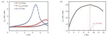
ObjectiveLaser beam propagating in atmosphere is affected by many effects such as turbulence, diffraction, self-focusing, and thermal blooming, which is an extremely complex physical process. Although the numerical simulation method can be used to predict the effects of different atmospheric conditions and beam parameters on laser propagation, its computational efficiency is insufficient for practical applications. Therefore, the study of scaling law becomes essential. However, on the one hand, most studies on the scaling law of laser atmospheric propagation focus on beam spreading. On the other hand, the thermal blooming effect causes the focus shift of a focused Gaussian beam, and the actual focus point is shifted to the position in front of the target plane, which severely degrades the beam quality at the target plane. In this paper, to achieve the maximum peak intensity at the target plane, the scaling law for the optimal focal length of a focused Gaussian beam under thermal blooming effect is investigated.MethodsThermal blooming effect of a laser beam propagating through atmosphere can be described by the paraxial wave equation and the hydrodynamic equation. A time-dependent four-dimensional code to simulate the focused Gaussian beam propagating in atmosphere is developed by using the multi-phase screen method, fast Fourier transform method, and difference method. In this paper, the method of pre-defocusing is employed to obtain the maximum peak intensity at the target plane. To predict the optimal focal length fopt under varying atmospheric conditions and beam parameters, this paper employs the controlled variable method to numerically analyze the effects of six scaling factors (initial laser power P, atmospheric wind speed v, atmospheric absorption coefficient α, initial beam width w0, target plane distance z0, and wavelength λ)on fopt. Through physical analysis and extensive numerical calculations, a formula of the optimal focal length fopt relating with the six scaling factors is established.Results and DiscussionsIn this paper, the method of pre-defocusing is employed to determine the optimal focal length of the lens, thereby achieving the maximum peak intensity at the target plane (Figs. 1 and 2). First, three scaling factors (P, v, and α) are considered , which significantly affect the intensity of thermal blooming effect. The generalized thermal distortion parameter N is a physical quantity used to describe the intensity of thermal blooming effect. A scaling law between fopt and N is investigated [Fig. 3 and Eq. (10)]. In contrast, when the other three scaling factors (z0,w0,andλ) are changed, both the intensity of the thermal blooming effect and the intensity of the diffraction effect are altered (Figs. 4?6). Therefore, it is necessary to modify Eq. (10). The scaling law of fopt relating with N, z0 and w0 is modified on the basis of Eq. (10) [Fig. 7 and Eq. (13)]. This scaling law can predict the optimal focal length under various atmospheric conditions and beam parameters. When N<11 and Fresnel number NF>4, this scaling law is applicable, and the mean relative error is 5.2% [Fig. 8 and Eq. (13)]. Additionally, it is shown that the increase of peak intensity at the target plane after focusing is greater when N is larger (Fig. 9).ConclusionsIn this paper, a scaling law for the optimal focal length of a focused Gaussian beam considering atmospheric thermal blooming effect is studied. The method of pre-defocusing is employed to determine the optimal focal length of the lens, thereby achieving the maximum peak intensity at the target plane. Using the controlled variable method, the influence of six scaling factors (P, v, α, z0, w0, andλ) on the optimal focal length fopt is obtained by varying them, respectively. Then, the scaling law of fopt relating with the generalized thermal distortion parameter N, the target plane distance z0 and the initial beam width w0 is established. This scaling law is applicable when N<11 and Fresnel number NF>4. This scaling law can predict the optimal focal length under various atmospheric conditions and beam parameters, and the mean relative error is 5.2%. Additionally, it is shown that the increase of peak intensity at the target plane after focusing is greater when N is larger. It is worth noting that laser atmospheric propagation is a very complex physical process. In practical application, the beam quality at the target plane is also related to the beam quality at the source plane, beam truncation ratio, tracking accuracy, and atmospheric turbulence. The results obtained in this paper are useful for the application of laser atmospheric propagation.
Jun. 14, 2025Vol. 52 Issue 11 1105001 (2025)
Hong Lü, Yike Liu, Jiao Jing, Chen Zhang, Kunpeng Wang, and Ruikang Shao
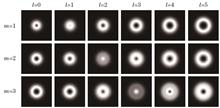
ObjectiveVector vortex beams (VVBs), as a new type of structured light with anisotropic spatial polarization and phase, carry orbital angular momentum related to the phase distribution and possess potential application values in fields such as optical manipulation, high-resolution imaging, and optical information transmission. Currently, there are scarce studies on the correlation between the polarization and phase topological charges of VVBs. Additionally, in contrast to scalar vortex beams, research on the interference and diffraction measurement of the orbital angular momentum of VVBs is relatively rare. This paper explores the correlation between the polarization and phase topological charges of VVBs, realizes the determination of topological charges through polarization methods, and investigates the interference and diffraction measurement approaches of the orbital angular momentum of VVBs, which is anticipated to broaden the thinking for the measurement and application of the orbital angular momentum of VVBs.MethodsBased on the field distribution characteristics of VVBs with different polarization orders and phase topological charges, this paper studies the correlation issue between the polarization order and phase topological charge values of VVBs and analyzes the influence of changes in the azimuthal angle and ellipticity angle on the polarization state and orbital angular momentum of VVBs. The orbital angular momentum measurement method of VVBs is analyzed by exploiting the characteristics of double-slit interference fringes, and the diffraction effects of VVBs with different aperture diaphragms are simulated and calculated. By comparing the diffraction spot shapes of different apertures, parameters including the phase topological charge and polarization order are derived, and the orbital angular momentum measurement method of VVBs is studied.Results and DiscussionsThe innovative results of this paper are as follows:1) According to the intensity and phase distributions of VVBs with different polarization orders and phase topological charges, the relationship of the light intensity and phase with the polarization order and phase topological charge values is analyzed. It is discovered that the phase topological charge and polarization order of VVBs respectively affect the sizes of the phase singularity and polarization singularity of the beams. The numbers of peripheral and central bifurcations of the beam phase distribution correspond to the polarization order and phase topological charge (Figs. 1?3). The ellipticity angle and azimuthal angle in the polarization matrix term of the vector vortex field have an impact on the polarization distribution of the field, the ellipticity angle affects the distribution range of light intensity, and the azimuthal angle causes a related rotation in the distribution direction of polarization state (Figs. 4?7).2) A double-slit interference simulation experiment of VVBs is carried out. It is found that when the polarization order and the absolute value of the phase topological charge are equal, the central dark core disappears. When the phase topological charge is l, the width of the interference fringe distortion is l stripe, and the direction of the interference fringe distortion is also related to the phase topological charge. When the phase topological charge is positive, the fringes twist to the right, and when the phase topological charge is negative, the fringes twist to the left. Moreover, the double-slit interference of VVBs with different polarization orders changes the size of the polarization singularity (Fig. 8).3) Through the diffraction calculation of VVBs after passing through single slit, right-angle triangular aperture, etc., the relationship of the diffraction pattern morphology with the phase topological charge value and polarization order of VVBs is compared and analyzed. It is found that when the polarization orders and phase topological charges of VVBs after passing through right-angle triangular hole diaphragms are simultaneously opposite numbers, the diffraction spot undergoes a phase shift related to the absolute value of the polarization order (Figs. 9?14).ConclusionsThe research findings indicate that the polarization order and the phase topological charge value jointly determine the intensity and phase distributions of VVBs. During the transmission process of VVBs under different polarization conditions, the vortex phase distribution remains relatively stable, and the alteration of the ellipticity angle leads to the difference in the polarization state distribution. Based on the regular changes in the fringe distribution after interference, the polarization order and the phase topological charge value of VVBs can be determined. When the VVBs pass through the right-angle triangular aperture diaphragm, the diffraction spot undergoes a phase shift related to the absolute value of the polarization order only when the polarization orders are opposite to each other, which suggests that single-slit diffraction is more conducive to the determination of the polarization order value, while right-angle triangular aperture diffraction is more effective for the determination of the phase topological charge.
Jun. 14, 2025Vol. 52 Issue 11 1105002 (2025)
Zhihui Li, Kai Zhang, Wuli Hu, Mingxia Feng, Kai Jia, Zheqiang Zhong, and Bin Zhang
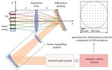
ObjectiveIn a fiber array spectral beam combining (SBC) system, imperfections such as installation deviation of the fiber array, linewidth broadening, and thermal effects of the optical elements and internal optical channel coexist and interact with each other, leading to degradation of the combined beam quality. Specifically, the displacement deviation, rotation angle, linewidth broadening, and divergence angle of the fiber laser emitters independently affect the combined beam, leading to non-common-path phase perturbations in each sub-beam. In addition, thermal effects of the diffraction grating and internal optical path introduce aberrations, collectively referred to as common-path thermal aberrations. As the non-common-path phase perturbations and common-path thermal aberrations increase, the degradation of the combined beam quality inevitably becomes more severe. To date, an in-depth analysis of the comprehensive degradation effects and correction characteristics of the combined beam quality has been insufficient. Therefore, studying the integrated degradation and correction characteristics of the combined beam quality under these imperfections, particularly with adaptive optics (AO), is crucial for the effective management and control of beam quality in SBC systems.MethodsThis study presents a theoretical and numerical analysis aimed at improving the beam quality of spectrally combined fiber lasers using adaptive optics. First, a physical model is established for the fiber SBC system for the imperfect factors. It consists of four components: an AO-based SBC system, an optical transmission model, a physical model for the thermal deformation of the multilayer dielectric grating (MDG), and a multifield coupling interaction model that describes the light-fluid-solid interactions (LFS-MFCI) within the internal optical path. The AO-based SBC system is primarily composed of three elements: the SBC, expanding laser beam, and AO systems. Ray tracing and diffraction integral methods are employed to develop and solve the optical transmission model for the SBC system. Additionally, finite element models are constructed for the MDG and LFS-MFCI. This enables us to simulate and analyze the temperature distribution and thermal deformation in the MDG and the internal optical path after 60 s of irradiation at an initial temperature of 20 ℃ and a power density of 1000 kW/cm2. Subsequently, the degradation mechanisms and characteristics of the combined beam quality are investigated by categorizing the aberrations within the SBC system into two types: noncommon-path phase perturbations and common-path thermal aberrations. Finally, we discuss strategies for enhancing the spectrally combined beam quality using adaptive optics and simulations.Results and DiscussionsIn the presence of imperfections such as displacement deviation, rotation angle, linewidth broadening, and divergence angle, the intensity distribution of the combined beam irradiating the multilayer dielectric grating displays a Gaussian-like profile that varies with the effect degree of these imperfections. Assuming an initial temperature of 20 ℃ and a power density of 1000 kW/cm2 for the incident laser, both the temperature and thermal deformation gradually decrease from the center toward the edge of the MDG after 60 s irradiation, approximating a Gaussian-like distribution. Moreover, the maximum temperature and thermal deformation of the MDG demonstrate a nearly linear increase with increasing incident laser power density (Fig. 5). In the axial cross section of the optical transmission, the temperature distribution and heat source distribution of the flow field within the internal optical path align with the Gaussian-like distribution of the laser irradiation. The peak values of the temperature and heat source are situated at the center of the optical path and reflector, respectively (Fig.7). The accumulated optical path difference induced by thermal effects in the gas is the primary contributor to the optical path differences, which significantly exceeds the thermal deformation on the surface of the reflector (Fig.8). Under the influence of non-common path phase perturbations and common path thermal aberrations, the far-field β factor of the combined beam increases, indicating deteriorating beam quality. After correction with the AO system, the far-field β factor decreases and approaches 1, demonstrating a significant improvement in the quality of the combined beam (Fig.10). Under the specific boundary conditions considered, the rotation angle of the fiber array is identified as the primary factor affecting output beam quality. When the variance of the rotation angle exceeds 1.5 mrad, the corrected far-field β factor remains higher than 1.5, indicating that the beam quality is still inadequate. Additionally, the degradation of the beam quality caused by the common-path thermal effects and optical path is comparatively less severe than that caused by non-common-path phase perturbations. The thermal effects are nearly uniform across each subbeam in the SBC system, making the correction through AO more manageable. The AO system exhibits superior correction capabilities for low-order common path aberrations resulting from thermal effects as opposed to high-order aberrations, thereby significantly enhancing the combined beam quality of the SBC system (Fig.12).ConclusionsThis study investigates the degradation and correction characteristics of the fiber array SBC system based on the established physical model of the fiber array with imperfect factors. The results indicate that both non-common-path phase perturbations and common-path thermal aberrations degrade the combined beam quality, which can be corrected by the AO system. Notably, AO demonstrates better correction capabilities for common-path thermal aberrations than for non-common-path phase perturbations. However, the combined beam quality after correction with the AO is still not sufficient for practical applications, particularly when the degradation of the combined beam quality is severe because of aberrations in the SBC system. Therefore, the control and management of the fiber array and other optical elements are crucial for reducing noncommon-path phase perturbations and alleviating the effects of common-path thermal aberrations within the SBC system.
Jun. 14, 2025Vol. 52 Issue 11 1105003 (2025)
Ziheng Zhang, Xiqian Fan, Gang Jin, Ziren Luo, and Heshan Liu
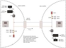
ObjectiveThe Taiji Program, led by the Chinese Academy of Sciences, is a space-based gravitational wave detection mission designed to detect gravitational wave signals in the frequency band of 0.1 MHz to 1 Hz in deep space. The main auxiliary functions of the laser link in the Taiji Program are intersatellite laser communication, ranging, and clock noise transfer. To integrate these functions within the same laser interferometric link used for gravitational wave detection, the mission proposes to implement sideband frequency doubling for clock noise transfer to suppress clock noise. Furthermore, pseudorandom code spread spectrum modulation is employed to achieve intersatellite laser communication. At present, research on the auxiliary functions of laser links for space gravitational wave detection remains limited. These functions often operate independently in separate systems, and no previous studies have tested the coupling of these auxiliary functions within a single laser link. This study aims to fill this gap by analyzing and designing parameters for the coupled modulation of clock signals and pseudorandom codes through simulation and experimental methods. The study aims to validate the feasibility and performance of the dual-modulation scheme within a single laser link, achieving functional integration of the interferometric auxiliary functions in the Taiji Program.MethodsThis study examined the requirements, principles, and methods for using a laser link to achieve intersatellite clock noise transfer and laser communication. It discussed the coupling relationship between the two functions to establish parameter planning. To validate the concept, a ground-based optical experiment was set up to simulate the laser interferometric link between the two satellites. The setup involved two independent signal generators acting as clock sources for the system clocks of the satellites. A power combiner was used to couple the communication information and the clock signal. The combined signal was then modulated into two laser carriers using an electro-optic modulator for interference testing. The phase information was extracted, and the data were demodulated through phase-locked and delay loops. Finally, the suppression results of the clock noise and the communication bit error rate were determined through data post-processing using MATLAB.Results and DiscussionsThe experimental and simulation results reveal that simultaneously modulating the clock signal and pseudorandom code in the laser link introduces a measurable impact on the main detection signal. Specifically, as the modulation depths of both signals increase, the signal-to-noise ratio of the main detection signal decreases. Furthermore, a coupling effect was observed between the clock noise sidebands and the sidelobes of the pseudorandom code. When the modulation depth of the pseudorandom code is relatively high, the signal-to-noise ratio of the sidebands becomes constrained and decreases. In extreme cases, sidebands may be overshadowed by sidelobes, which renders effective clock noise extraction impossible. Conversely, if the modulation depth of the pseudorandom code is relatively low, environmental noise significantly affects the performance, greatly increasing the communication bit error rate. Through experimental analysis and parameter optimization, the clock noise suppression effect achieved surpasses 2π×10-5 rad/Hz1/2 in the frequency bands of 0.1?1.0 Hz and 0.1?0.5 mHz, meeting the requirements of the Taiji Pathfinder. This validates the effectiveness of the clock noise transfer scheme by simultaneously coupling the pseudorandom code and the clock signal modulation in the laser link. At the same time, the communication bit error rate is successfully maintained below 10-6 (Fig. 19).ConclusionsThe auxiliary laser interferometry functions for gravitational wave detection in the Taiji Program mainly include clock noise transfer and intersatellite laser communication ranging. To meet the system design requirements that the sideband laser power in the laser link system does not exceed 10% of the total laser power and that the pseudorandom code modulation power remains below 1%, this study employs principle analysis and simulation fitting to design an optimized parameter structure for these functions. It also evaluates their integration within the same laser link. The influence of pseudorandom code modulation depth on the clock noise transfer was analyzed, leading targeted improvements. These enhancements enable clock noise suppression to reach a level better than 2π×10-5 rad/Hz1/2 in the frequency bands of 0.1?1.0 Hz and 0.1?0.5 mHz. This performance is consistent with the suppression effect achieved using the sideband frequency doubling method. By reducing the pseudorandom code modulation depth to improve the signal-to-noise ratios of the main and sideband signals, the communication bit error rate is successfully maintained below 10-6. Overall, this work demonstrates the successful integration of auxiliary laser link functions, validates the effectiveness of the proposed two schemes, and lays experimental and theoretical groundwork for the comprehensive integration of interferometric auxiliary functions.
Jun. 09, 2025Vol. 52 Issue 11 1106001 (2025)
Zhe Huang, Changhui Liu, Hao Wu, Wei Shi, Shunbin Wang, and Pengfei Wang
ObjectiveAll-fiber lasers offer significant advantages, including excellent beam quality, high integration, and a simple structure, making them a crucial approach for achieving high-power and high-efficiency laser outputs. Fiber splicing is a key technology in the realization of all-fiber laser outputs, as low-loss and high mechanical strength splicing can substantially enhance the optical-to-optical conversion efficiency and the long-term stability of the fiber laser. At present, the output power of quartz fiber lasers has reached the level of ten thousand watts, a development that is closely linked to the advancement of mature fusion technologies for quartz fibers and the fabrication techniques of optical fiber devices. However, due to the limitations of the material transmission window, the output wavelength of quartz fiber lasers is restricted to less than 2.5 μm, preventing the realization of mid-infrared laser output at longer wavelengths. Multi-component fibers, such as heavy metal oxides and fluorides, possess a broad transmission window in the mid-infrared band, and can be utilized for the development of mid-infrared fiber laser devices. At present, the most mature pump sources for such systems are semiconductor lasers or fiber lasers with a quartz fiber-coupled output. Fusion splicing between quartz output tail fibers and multi-component fibers is a critical technology for the integration of all-fiber lasers. To address the aforementioned challenges, this study investigates the fusion splicing between quartz optical fibers and various multi-component optical fibers, including heavy metal oxides, fluorides, and other multi-component optical fibers. By adjusting key parameters such as the main fusion power and the offset distance of the fire head, the effects of splicing loss and mechanical strength in fiber optic connections between single-mode silica fiber (SMF-28e+) and various other fibers, namely, bismuthate fiber (PBB), zirconium fluoride-based fiber (ZBYA), and fluorotellurite fiber (TBY), as well as those between PBB and TBY, ZBYA and TBY, and PBB and ZBYA, are investigated. The findings indicate that the effectiveness of fusion splicing between different types of optical fibers is closely related to the transition temperature difference between the respective optical fibers. This study establishes a foundation for further research and development of high-power all-fiber lasers and providing a significant reference for the development of optical fiber fusion splicing technology.MethodsIn this study, the asymmetric fusion splicing method is employed due to the differences in the transition temperatures of the various optical fibers. The low fusion loss and reduced mechanical strength of dissimilar optical fibers in this study are attributed to the mismatch in mode field diameter. In the specific welding process, direct fusion following the inherent procedure of the fusion splicer would result in excessively high loss. Therefore, it is necessary to iteratively adjust parameters such as the main fusion light power, main fusion light duration, fiber end-face interval setting, overlap amount, and fiber offset during the experiment to achieve the lowest possible fusion loss while ensuring the highest mechanical strength.Results and DiscussionsIn this study, fiber splicing is conducted on four different types of dissimilar optical fibers, and the splicing results of three types of dissimilar soft glass fibers are demonstrated. Through repeated experiments, it is determined that the primary factors influencing splicing loss and mechanical strength are the welding power and head offset, respectively. In addition to mode field mismatch, the transition temperature of the fiber itself is found to be a critical factor affecting the splicing outcome. During the experiment, the insertion loss at the fusion point is measured using the truncation method (Fig. 3). A 1150 nm laser is coupled into fiber 1, and the fiber splicing loss is calculated by comparing the output powers before and after splicing fiber 2. Overall, when the dissimilar fiber reaches the optimal fusion state, the fiber fusion loss decreases to varying degrees with an increase in the main fusion optical power. However, once the power exceeds a certain threshold, the loss increases sharply, indicating that the fusion point has been burned out (Fig. 4). When quartz fibers are fused with soft glass fibers, the loss is generally low. The lowest loss is observed in the fusion of SMF-28e+ and PBB, where the loss is only 0.04 dB when the main fusion optical power is 72 bit. This is because the transition temperature difference between the quartz and soft glass fibers is greater than that of the heterogeneous soft glass fiber fusion splicing, resulting in better core coupling during annealing and cooling. The highest fiber-splicing loss in the experiment is observed between the PBB and ZBYA fibers. As the main fusion power is gradually increased to 70 bit, the loss decreases from 7.7 dB to a minimum of 0.27 dB. However, when the power is further increased to 82 bit, the splicing point burns out, causing the loss to rise sharply to a maximum of 8.2 dB. Based on the transmission characteristics in the optical fiber, it can be concluded that the more ideal the shape of the fusion point, the lower the splicing loss. In the study of fusion splicing between dissimilar optical fibers, it is essential to consider not only the splicing loss but also the mechanical strength to meet application requirements. Prior to reaching the optimal offset of the fire head, a smaller offset results in lower mechanical strength. Once the optimal mechanical strength is achieved, further increases in the offset lead to a gradual decline in mechanical strength (according to the different dissimilar fiber fusion, the offset of the fire head is controlled within a certain range). The fusion point with the lowest mechanical strength is observed in the fusion of SMF-28e+ and PBB, where the maximum mechanical strength reaches 148 gf (1 gf=0.0098 N) at a head offset of 125 μm. In contrast, the best performance is achieved in the fusion of PBB and ZBYA, with the maximum mechanical strength reaching 324 gf at the optimal head offset of 20 μm (Figs. 5 and 6).ConclusionsIn this study, when different types of dissimilar optical fibers are spliced, the splicing parameters affecting the splicing loss and mechanical strength of the optical fiber are primarily the main fusion optical power and the offset of the fire head. By controlling these variables and keeping the other splicing parameters fixed, the results for the splicing of SMF-28e+ and PBB, SMF-28e+ and ZBYA, SMF-28e+ and TBY, PBB and TBY, ZBYA and PBB fibers are obtained. The minimum splicing loss between quartz fiber and soft glass fiber is 0.04 dB (PBB and SMF-28e+), with a maximum mechanical strength of 148 gf. For dissimilar soft glass fiber fusion splicing, the minimum loss is 0.19 dB (PBB and TBY), with a maximum mechanical strength of 220 gf. These results indicate that the transition temperature difference between dissimilar fibers is a key factor influencing the final fusion splicing outcome. We believe that all-fiber systems will find increasingly broader applications as research on dissimilar fiber splicing extends to the mid-infrared band.
Jun. 13, 2025Vol. 52 Issue 11 1106002 (2025)
Shang Lu, Lingling Men, Zihao Wang, Chunhua Li, Jing Liang, Tong Wang, Shu Yang, Siyu Chen, Xiaoyang Liu, Luyan Zhang, Yuanying Han, Haoyue Yan, Luping Yan, Xiaolong Wang, Na Ma, Zhenqiang He, Zhiyong Ke, Bo Li, Xiaoye He, and Lan Dong
ObjectiveThe circumference of the high energy photon source (HEPES) storage ring is about 1360 m, with 288 girders (96 three-magnet girders, 96 five-magnet girders, and 96 eight-magnet girders) and 1776 magnets. In order to improve the installation efficiency of the storage ring, each girder is usually first pre-aligned in the laboratory, and then transported to the storage ring to participate in the tunnel alignment. Based on simulation and physical design of the accelerator, the standard deviation for the pre-alignment adjustment of magnets on one girder in transverse and vertical directions must be below 10 μm.MethodsTo efficiently complete the pre-alignment work of HEPES and simultaneously ensure the pre-alignment accuracy, a four-station laser tracker multilateration measurement system is used for measuring and real-time monitoring the magnet position deviation. The ranging accuracy of laser trackers is much better than that of angle measurement. The multilateration measurement system uses four laser trackers to measure the distance to the target point on every magnet, and a rank-defect free-network adjustment model is used to solve the coordinates of the station and target points. The multilateration measurement system can avoid the errors of angle measurement of laser trackers, thus obtain a high-precision result. In order to improve the work efficiency for pre-alignment, a standardized operating process is established, including girder fiducialization and calculation of the theoretical values of pre-alignment, sextupole magnet and mover alignment, and conventional magnet alignment. In order to reduce the residual error of beam correction and improve the dynamic aperture, a sextupole magnet mover is developed to perform beam-based alignment online. The mover can realize transverse and vertical motions. Therefore, it is necessary to align the movement direction of the mover until it is parallel to the corresponding direction of the coordinate axis, and then carry out the alignment of the sextupole magnet. Since there is no elevation adjustment mechanism between mover and sextupole magnet, it is determined that the mover can be fixed on the girder directly and the shims are inserted in the interface of magnet and mover using a special lifting fixture to adjust the flatness errors.Results and DiscussionsThree work stations are built in the laboratory for pre-alignment. All work stations are designed to accomplish alignment of all three girders. Through the continuous optimization of the pre-alignment process, the pre-alignment efficiency for the three-magnet girder and the five-magnet girder are 0.5 d per girder and 1 d per girder, respectively. For the eight-magnet girder, three sextupole magnets and the mover need pre-alignment after the five conventional magnets are completed. The motion direction of the mover is made parallel to the theoretical direction by the lateral adjustment mechanism of the mover, and then the error in the elevation direction of the sextupole magnet is adjusted to within 10 μm by insertion of shims (Fig. 9). This pre-alignment scheme for the sextupole magnet and the mover has good results in practice, and the time taken to pre-alignment each eight-magnet girder is reduced from 5 d per girder at the beginning to 1 d per girder. The multilateration measurement scheme adopted for pre-alignment can be adjusted according to the size of the target to be measured and the size of the environment, so as to meet the needs for high-precision measurement and adjustment of different equipments.ConclusionsIn the actual pre-alignment process through continuous exploration, one needs to sum up standardized operating procedures of the storage ring unit pre-collimation, prepare the pre-collimation process control table, and strictly control the pre-collimation process and the results of each unit. In the end, 288 standard girders are pre-aligned on time with an accuracy of better than 10 μm. It shows that the pre-alignment process is reasonable and the accuracy of the measurement scheme meets the requirements. The alignment accuracy of the multilateration system can still be improved by increasing the height difference of four stations. Furthermore, this laser tracker-based multilateration method can be applied to other high precision fields, for example, the field of industrial measurement.
Jun. 06, 2025Vol. 52 Issue 11 1101001 (2025)
Yuhang Lu, Yun Chen, Yue Yu, Luwen Yang, Zhiqiang Wan, Jilong Tang, and Zhipeng Wei
ObjectiveThe transverse mode instability (TMI) effect in single-fiber fiber lasers is one of the main factors limiting their power scaling. In this paper, we design an industrial-grade 7 kW all-fiber laser oscillator using a hybrid pumping scheme, which effectively mitigates the occurrence of TMI. Based on traditional large mode area ytterbium-doped fibers (LMA-YDFs) with a core/inner cladding diameter of 30/400 μm and commercial unstable wavelength pump sources, the TMI threshold is significantly increased under dual-wavelength hybrid pumping conditions at 915 nm and 976 nm. The output power of the single-stage fiber laser is increased to 7.06 kW using a bidirectional pumping structure, with a Raman suppression ratio greater than 42.23 dB. This laser operates stably at an output power of 7 kW with a power fluctuation within 1% during a 110 h aging test. Additionally, high-reflection resistance tests are conducted, and the laser maintains good stability when perforating high-reflection materials, indicating its readiness for use in most industrial applications.MethodsIn this study, we design a high-power fiber laser oscillator based on double-clad ytterbium-doped fiber with a core/clad diameter of 30/400 μm and an absorption coefficient of 0.65 dB/m at 915 nm. The fiber is fixed onto a water-cooled plate with a minimum coil diameter of 13 cm. By utilizing both 915 nm pumping and a combination of 915 nm and 976 nm pumping, we compare the laser output characteristics under different pumping conditions. First, in the case of forward pumping, a 976 nm laser diode (LD) with an unstable wavelength is used as the pump source to test the threshold of TMI. Second, the pump wavelength is changed to a mixed pump wavelength configuration, and its output characteristics are compared with those of pumping solely at the 976 nm wavelength. Finally, a bidirectional pumping approach is employed to achieve a higher power output.Results and DiscussionsWhen pumping with a single 976 nm wavelength pump source, the forward pumping TMI threshold of our system is tested to be 1.36 kW. By solely changing the pump wavelength to a mixed wavelength configuration, the forward TMI threshold exceeds 2.12 kW (Figs. 2 and 3). This indicates that the mixed pumping method effectively suppresses TMI. After confirming the advantages of mixed pumping, the pumping configuration is changed to bidirectional pumping, which increases the pump injection power while mitigating the thermal effects generated in the fiber. Ultimately, at a pump power of 9.3 kW, a laser output power of 7.06 kW is achieved, with an optical-to-optical efficiency of 75.9%. In the absence of TMI effects, the Raman suppression ratio is 42.3 dB. At the maximum power output, the beam quality factor (M2) is approximately 2.16 (Fig. 4). Finally, power stability tests and high-reflection resistance tests are conducted on the designed fiber laser oscillator to verify its feasibility for industrial applications.ConclusionsThis paper presents an industrial-grade end-pumped all-fiber laser oscillator that achieves a high output power of 7 kW and demonstrates superior stability. Commercial high-power LDs with unstable wavelengths of 915 nm and 976 nm are employed as pump sources. The forward TMI thresholds of the fiber laser oscillator are compared under a single 976 nm pumping scheme and a hybrid pumping scheme using both 915 nm and 976 nm. Experimental results indicate that the hybrid pumping method significantly enhances the TMI threshold. On this basis, a bidirectional hybrid pumping scheme is ultimately adopted to achieve a laser output power of 7.06 kW, with an optical-to-optical conversion efficiency reaching 75.9%. Furthermore, the laser oscillator maintains a Raman suppression ratio of 42.23 dB in a 15 m long output pigtail fiber with a core/clad diameter of 34/250 μm, and a beam quality factor M2 of 2.16. In terms of industrial application stability testing, after operating at a high output power of 7 kW for 2 h, the laser superior performance against back-reflection light is verified using copper as the high-reflective material in the high-reflection resistance test. By optimizing the pumping wavelengths of the fiber oscillator and balancing TMI and SRS, further increase in the output power of this oscillator is expected in the future. This paper provides a reliable solution for constructing end-pumped bidirectional fiber lasers with output powers of 7 kW and above for industrial applications.
Jun. 07, 2025Vol. 52 Issue 11 1101002 (2025)
Guanting Song, Xu Zhou, Ziyang Zheng, Jiaxin Cao, Qiang Wu, and Jingjun Xu
ObjectiveSilicon has been extensively utilized in fiber-optic communications, photodetection, and solar cells owing to its low purification cost, high purity, and compatibility with complementary metal-oxide-semiconductor (CMOS) technology. However, silicon-based photodetectors are restricted in near-infrared (NIR) photodetection due to their indirect bandgap of 1.12 eV at room temperature. To address this limitation, significant research efforts have focused on NIR photodetection using bulk materials such as germanium (Ge), cadmium sulfide (CdS), and gallium arsenide (GaAs), as well as two-dimensional materials like graphene. Among these, femtosecond-laser hyperdoped silicon photodetectors have emerged as promising candidates for silicon-based NIR photodetection. These devices combine extended spectral responsivity beyond 1100 nm where conventional silicon photodetectors are unable to respond with cost-effective CMOS-compatible fabrication, simultaneously achieving broadband high responsivity and industrial-scale manufacturability. Despite these advantages, the underlying mechanisms of femtosecond-laser hyperdoped silicon photodetectors remain poorly understood. Further research on the working mechanism of femtosecond-laser hyperdoped silicon photodetectors will not only facilitate in-depth tuning of the photodetectors, but also provide important guidance for further functional design of femtosecond-laser hyperdoped devices. In this study, we report a low-concentration femtosecond-laser hyperdoped silicon photodetector demonstrating light-intensity inverse-saturation response characteristic and bias inverse-saturation response characteristics. This unique inverse-saturation response characteristic offers a robust solution for photodetection in environments with intense background illumination. Furthermore, by systematically analyzing current-output properties of hyperdoped silicon devices under different light intensities and reverse biases, our findings provide critical insights into working mechanisms of femtosecond-laser hyperdoped silicon photodetectors, facilitating their future performance enhancement and application-specific customization.MethodsIn this study, sulfur-hyperdoped silicon is fabricated by irradiating N-type single-crystalline (100) silicon wafers with a femtosecond laser in an SF6 atmosphere. A Pockels cell electro-optic switch is utilized to precisely control the number of scanning laser pulses, enabling the preparation of two distinct doping concentration levels. Hyperdoped silicon samples subsequently undergo rapid thermal annealing, followed by thermal evaporation of aluminum electrodes to prepare photodetectors. The surface morphology of the hyperdoped silicon is characterized using field-emission scanning electron microscopy (SEM), while depth-resolved dopant concentration profiles are quantitatively analyzed via secondary ion mass spectrometry (SIMS). For the low-concentration sulfur-hyperdoped silicon photodetector, spectral responsivity measurements are performed under varying reverse biases (DC power supply) and incident light intensities (modulated by a calibrated neutral density filter). Current-output properties are systematically investigated at different reverse biases and light intensities.Results and DiscussionsThe high-concentration sulfur-hyperdoped silicon exhibits quasi-periodic peak structures (about 1 μm average height) distributed across the surface. In contrast, the low-concentration sulfur-hyperdoped silicon displays a flat morphology without microscale surface features. SIMS measurements reveal a sulfur peak concentration exceeding 1020 cm-3 within a 600 nm depth for the high-concentration sample, whereas the low-concentration sample achieves a peak doping concentration above 1018 cm-3 confined to a 50-nm subsurface region [Fig. 2(c)]. Photocurrent measurements reveal that the low-concentration hyperdoped silicon photodetector exhibits a unique inverse-saturation response characteristic under illumination intensities exceeding 166.2 μW, where the photocurrent decreases with increasing light intensity [Fig. 3(a)]. This inverse-saturation response characteristic is modulated by the irradiation wavelength, with the most pronounced effect observed under 1000 nm illumination [Fig. 4(b)]. By regulating the photodetector’s reverse bias between 2?8 V, we achieve controllable modulation of the inverse-saturation intensity (Fig. 5). At an illumination intensity of 5 μW, the photodetector demonstrates a peak spectral responsivity of 252.71 A/W at 1000 nm (Fig. 8), surpassing that of commercial silicon-based photodetectors by over two orders of magnitude, while possessing a unique light inverse-saturation response characteristic, indicating superior weak-signal photodetection capability in high-intensity optical interference environments.ConclusionsIn this study, two sulfur-hyperdoped silicon photodetectors with distinct doping concentrations are successfully fabricated by adjusting the pulse number of femtosecond laser irradiation on silicon. We observe both light-intensity inverse-saturation response characteristic and bias inverse-saturation response characteristic in the low-concentration hyperdoped silicon photodetector. To explain the light-intensity inverse-saturation phenomenon, we extend the existing defect-assisted photoconductive gain model by incorporating discussions on the hole quasi-Fermi level variation in hyperdoped silicon under varying light intensities. Furthermore, the bias inverse-saturation mechanism is elucidated through the introduction of doping-generated junction effects on defect-assisted photoconductive gain. The refined model effectively describes the current-output characteristics of femtosecond-laser hyperdoped silicon under varying reverse biases and light intensities, providing critical insights for optimizing femtosecond-laser hyperdoped devices and advancing their exploration for environment-specific applications. Additionally, we develop a novel photodetector exhibiting a unique light-intensity inverse-saturation response characteristic. This device demonstrates straightforward fabrication, exceptional performance (peak spectral responsivity: 252.71 A/W), and dual functionality—sensitive weak-light photodetection coupled with distinct strong-light inverse-saturation response characteristic. The easily tunable inverse-saturation threshold and CMOS-compatibility position this technology as a promising solution for weak-signal photodetection in complex optical interference environments, showcasing significant application potential.
Jun. 06, 2025Vol. 52 Issue 11 1101003 (2025)
Weak‑Light Phase‑Locked Ground‑Based Experimental Validation and Noise Analysis of the Taiji Program
Chen Wang, Xuerong Gao, Keqi Qi, Shaoxin Wang, Pan Li, Peng Dong, Heshan Liu, and Ziren Luo
ObjectiveThis study tackles the critical challenge of inter-satellite laser power attenuation to the nanowatt (nW) level in the Taiji Program. We systematically validate the feasibility of weak-light phase-locking technology under extreme low-light conditions through ground-based experiments. Further, the key noise mechanisms that limit phase-locking precision are analyzed. The research objectives include the development of a mathematical model of the phase-locked loop suitable for long-baseline interferometry and the optimization of control parameters to address dynamic Doppler frequency shifts ranging across 5?25 MHz. Further, the contributions of shot noise, carrier-to-noise ratio (CNR) noise, phasemeter noise, and environmental noise are quantified, and the stability boundaries of phase locking under low CNR conditions, specifically at -86 dB-Hz is examined. By bridging the technological gap in ultra-weak-light phase locking in China, this study provides both theoretical and experimental foundations necessary for achieving picometer-level displacement measurements in the Taiji Program. This advances space-based gravitational wave detection from theoretical design to engineering implementation. Furthermore, the findings offer valuable insights into noise suppression strategies and system optimization.MethodsThe research team developed a modular, ground-based weak-light phase-locking verification system to simulate the inter-satellite low-light conditions. A master laser (Mephisto 500NEFC, wavelength: 1064 nm) was attenuated to 0.49 nW using a variable optical attenuator, simulating the weak signal from a distant satellite. Simultaneously, a slave laser served as a local oscillator, delivering a power of 20 μW. The two beams were coupled into a four-interferometer setup (fused silica substrate) within a vacuum chamber (10 Pa pressure) via a polarizing beam splitter. The interferometry unit employed a balanced detection scheme, where signals were captured through high-sensitivity avalanche photodiodes (Thorlabs APD430M/C, responsivity: 12 A/W, noise equivalent power (NEP): 0.45 pW/Hz1/2) and converted into electrical signals using transimpedance amplifiers. The closed-loop control unit, implemented on a field programmable gate array platform (Moku:Pro), integrated a 24-bit resolution phasemeter, dual-loop PID controllers (PZT loop bandwidth: 100 kHz, TEC loop bandwidth: 1 Hz), and a fourth-order Butterworth low-pass filter with a 50 kHz cutoff. Real-time CNR monitoring was performed using a spectrum analyzer. Further, an LTPDA Toolbox was used for the frequency-domain decomposition of residual phase errors across a range of 0.1 mHz to 100 kHz. Theoretical models were developed to represent key noise sources, including shot noise Sshot=hc /λP and CNR noise SCNR=10C/N0/10. These models were compared against experimental data to systematically analyze the noise contributions.Results and DiscussionsUnder weak-light conditions (0.49 nW, CNR=-86 dB-Hz), the system achieves a residual phase error of 6×10⁻⁵ rad/Hz1/2 (>0.02 Hz), approaching the theoretical CNR noise limit of 5.01×10⁻⁵ rad/Hz1/2 and corresponding to an equivalent displacement noise of 10 pm/Hz1/2. Under strong-light conditions (1.7 μW), the residual phase error decreases to 4.5×10⁻⁵ rad/Hz1/2, reaching the phasemeter’s noise floor, which is limited by a 10 bit ADC quantization and the 1.25 GSa/s clock jitter. Noise analysis reveals that the CNR noise dominates the high-frequency range (>0.1 Hz) under low CNR conditions, contributing over 60% of the total noise and exhibiting a 1/P attenuation trend as the weak-light power increases. Low-frequency residuals (<0.1 Hz) are significantly affected by thermal drift, with the interferometer’s Invar base (thermal expansion coefficient of 1.2×10⁻⁶ K-1) facilitating a phase drift of 2×10⁻⁴ rad/Hz1/2 at 1 mHz. Further, mid-frequency laser frequency jitter is suppressed by 40 dB via the dual-loop PID control system, demonstrating strong broadband disturbance rejection. Compared to LISA’s analog phase-locked loop (17 nW, 5×10⁻⁶ rad/Hz1/2) and Tsinghua University’s digital approach (9 pW, 5.2×10⁻⁴ rad/Hz1/2), this study demonstrates superior high-frequency performance at the nW level. However, the low-frequency stability must be further improved through active thermal control (±0.01 ℃).ConclusionsThis study provides conclusive validation of the weak-light phase-locking technology for the Taiji Program, achieving a precision of 10 pm/Hz1/2 at 0.49 nW. To the best of our knowledge, this is the first demonstration of CNR noise-dominated performance in China and the results successfully satisfy the Taiji mission’s displacement measurement requirement of 8 pm/Hz1/2. The research delineates the full-bandwidth noise distribution, identifying CNR noise as the dominant factor at high frequencies (>0.1 Hz), thermal drift as the primary influence at low frequencies (<0.1 Hz), and phasemeter electronic noise as the limiting factor under strong-light conditions. The proposed optimization strategies include low-noise APDs (NEP <0.1 pW/Hz1/2), photon-counting techniques for weak-light detection, and adaptive thermal control systems. The experimental results align with the theoretical models (<15% deviation), thereby confirming the reliability of the framework for space system simulations. Future work will focus on suppressing coupled multi-degree-of-freedom noise, such as vibration-thermal cross-sensitivity, and validating the system’s adaptability to in-orbit environmental conditions, including radiation hardening and microgravity effects. These advancements aim to accelerate the transition of the Taiji Program from laboratory research to practical deep-space applications.
Jun. 09, 2025Vol. 52 Issue 11 1101004 (2025)
Xinyu Li, Ziwen Huang, Zhengxi Li, Yunbin Cao, Zhanfeng Li, Liping Shang, Hu Deng, and Zhixiang Wu
ObjectiveBifocal devices can generate two focal points in the vertical or transverse direction, have the advantages of improving the depth and resolution of imaging as well as the transmission efficiency and quality of optical signals, and have a wide range of applications in optical communications, optical imaging, microscopy technology, and optical sensors. Traditional bifocal devices are limited by the Abbe diffraction limit, but recently optical super-oscillation provides a new technology for far-field super-resolution focusing, which can make the focused focal spot break through the diffraction limit. However, the existing bifocal super-oscillatory lenses rely on complex optimization algorithms, the device processing is difficult, and the device size is limited. Based on the principle of optical super-oscillation, combined with the binary particle swarm optimization (BPSO) algorithm and the angular spectrum diffraction theory, two single-focal focused binary phase super-oscillation masks with different focal lengths are designed, and the bifocal focused binary phase super-oscillation masks can be obtained by using the Boolean logic “AND” operation. A bifocal super-oscillation mask is loaded into a spatial light modulator (SLM) to generate a super-resolution bifocal focusing device. This method has the advantages of easy implementation and controllable design focal length, and has significant application potential in optical communication, biomedical imaging and other fields.MethodsThis paper consists of three core steps: first, for circularly polarized light (wavelength λ=632.8 nm), two binary phase super-oscillation masks (S-SOM1 and S-SOM2) are designed and optimized by using the BPSO algorithm and the angular spectrum diffraction theory with the corresponding focal lengths of f1=280000λ (177184 μm) and f2=300000λ (189840 μm), respectively. Second, a Boolean “AND” operation is performed on the phase distributions of the two masks to synthesize a bifocal super-oscillation mask (B-SOM), and the bifocal synchronous modulation is achieved by preserving the overlapping region of the phases. Finally, a far-field super-resolution bifocal focusing and measurement platform based on a spatial light modulator is designed and constructed, the B-SOM is loaded into the SLM in the form of a grayscale map, the scanning shot of the optical field with a step size of 0.05 mm is taken through the electrically-controlled displacement stage to obtain the distribution of the optical field, and the key parameters are extracted to verify the performance.Results and DiscussionsThe Boolean “AND” operation is performed on the phase distributions of the single-focal super-oscillation masks S-SOM1 and S-SOM2 obtained from the optimized design to obtain the phase distributions of the bifocal super-oscillation masks (Fig. 3). From the theoretical results, it can be seen that the transverse full widths at half maximum (FWHMs) of the two focal spots are 21.846 μm and 21.114 μm, respectively, which are lower than the diffraction limits of 22.277 μm and 23.495 μm, and super-resolution focusing has been realized in theoretical calculations (Fig. 5). The experimental results show that the designed bifocal device successfully realizes far-field super-resolution focusing. The longitudinal FWHMs of the bifocal are 4.523 mm and 4.198 mm, respectively (Fig. 7), and the transverse FWHMs are 20.333 μm and 23.353 μm, respectively (Fig. 8), which are lower than the Abbe diffraction limits of 22.225 μm and 23.650 μm. In addition, the bifocal sidelobe ratios are as low as 5.1% and 12.7%, respectively (Table 1), which effectively suppress the optical field crosstalk. The experimental focal spot positions (z=177.784 mm and z=189.184 mm) are in good agreement with the theoretical calculations, and the small deviations are due to the partial loss of the modulation phase after the logic “AND” operation.ConclusionsIn this paper, we propose a far-field super-resolution bifocal focusing method based on spatial light modulator, which is based on the principle of super-oscillation, and utilize the binary particle swarm optimization algorithm and the angular spectrum diffraction theory to design a single-focal binary-phase super-oscillation mask, and adopt the Boolean logic “AND” operation to generate a bifocal super-oscillation mask from two binary-phase super-oscillation masks with different focal lengths. Based on this method, the bifocal super-oscillation masks with working wavelength of 632.8 nm and focal lengths of 280000λ (177184 μm) and 300000λ (189840 μm) are designed and optimized, respectively. By loading the super-oscillation mask into a spatial light modulator without precision processing, far-field super-resolution bifocal focusing is experimentally demonstrated, with the peak intensity positions of the two focal spots located at 177784 μm and 189184 μm, respectively. The average FWHMs are 20.333 μm and 23.353 μm, respectively, which are lower than the Abbe diffraction limit. The low sidelobes are also maintained with ratios of 5.1% and 12.7%, respectively. The results significantly improve the control accuracy and resolution of far-field super-resolution bifocal imaging, which can be applied to the visible wavelength band and extended to other optical bands.
Jun. 07, 2025Vol. 52 Issue 11 1101005 (2025)
Xinyu Wen, Xuezong Yang, Weibiao Chen, Yan Feng, and Dijun Chen
ObjectiveSingle-frequency fiber lasers operating in the 1 μm wavelength regime have become pivotal for scientific and industrial applications, including gravitational wave detection, coherent lidar system, and optical atomic clock, where low intensity noise and high output power are paramount. Traditional pumping schemes for Yb-doped fiber amplifiers (YDFAs) relying on 976 nm laser diodes (LDs) suffer from inherent limitations, including large quantum defect causing excessive thermal loading in the gain fiber and pumping-induced intensity fluctuations degrading the amplified laser stability. These limitations hinder their applicability in precision interferometry and frequency metrology, where even minor intensity fluctuations will propagate into systematic errors. Recent studies have explored tandem pumping strategy to mitigate these issues. By employing a pumping wavelength closer to the signal wavelength (e.g., 1018 nm pumping for 1064 nm amplification), quantum defect is minimized, and thermal deposition and excessive amplified spontaneous emission (ASE) are reduced. However, the relative intensity noise (RIN) characteristics of such tandem-pumped YDFAs, especially under high-power operation, are scarcely investigated. This study aims to analyze the RIN transmission and suppression mechanisms in a single-frequency YDFA at 1064 nm with maximum output power of 4 W, which is tandem-pumped by a single-frequency high-power laser at 1018 nm. Furthermore, in the same YDFA system, we explore the RIN performance under tandem pumping against that under conventional 976 nm LD pumping to quantify the RIN suppression in the frequency band of 10 Hz?10 MHz. This work provides a feasible method for designing low-RIN, high-power fiber amplifiers suitable for quantum technology and precision optical systems.MethodsThe single-frequency 1064 nm fiber laser consists of a semiconductor distributed feedback (DFB) laser at 1064 nm with output power of 23 mW and a one-stage YDFA with gain fiber length of 4 m. The tandem pumping laser at 1018 nm is formed with a single-frequency semiconductor DFB seed laser and two-stage YDFAs. For the second YDFA at 1018 nm, a 27 W 976 nm LD is used as the pumping source and the active fiber is a 1.5 m long Yb-doped double-cladding fiber with core and cladding diameters of 15 μm and 130 μm. The maximum output power of the single-frequency 1018 nm laser reaches about 10 W. Two band-pass fiber filters at 1018 nm with bandwidth of 2 nm are spliced with the two ends of the first YDFA to remove the ASE generated from the seed and the first amplifier. The 1018 nm tandem pumping laser is coupled into the 1064 nm YDFA through a 1018/1064 nm wavelength division multiplexer (WDM). For comparison, an LD at 976 nm with maximum power of 27 W is employed as conventional pumping scheme for the 1064 nm YDFA. Both the 1018 nm tandem pumping and the 976 nm LD pumping can amplify the 1064 nm seed laser to 4 W power. The RIN measurements are conducted using a photodetector (150 MHz bandwidth) and a spectrum analyzer (26.5 GHz bandwidth).Results and DiscussionsAt the output power of 4 W of the 1064 nm YDFA, the RIN level of the 1064 nm laser pumped using a single-frequency 1018 nm laser is below -125 dBc/Hz in the full range of 200 Hz?10 MHz, and the RIN level of the tandem-pumped YDFA output is reduced by 15 dB compared to that pumped using the 976 nm LD in the frequency range from 100 Hz to 100 kHz [Fig. 6(a)]. Notably, in the frequency range of 200 Hz?50 kHz, the RIN level of the tandem-pumped laser is even lower than that of the seed laser. The better performance of the RIN suppression of the tandem pumping scheme is attributed to the high spectral purity and the low thermal loss. The spectra of the 1064 nm seed laser, the amplified 1064 nm laser pumped by 976 nm LD, and the amplified 1064 nm laser pumped by the 1018 nm single-frequency laser are investigated and shown in Fig. 6(b). The result reveals that the spectral proportion of the ASE is 0.31% for tandem-pumping and 0.58% for 976 nm LD pumping.ConclusionsThis study validates the effectiveness of tandem pumping for RIN suppression in single-frequency YDFAs. By utilizing a single frequency pumping laser at 1018 nm, the ASE and quantum defect are reduced in the 1064 nm YDFA, enabling a 15 dB RIN reduction in the frequency band of 100 Hz?100 kHz. While low-frequency (<100 Hz) noise remains terrible due to the excessive thermal and ambient noises, this passive RIN reduce strategy using tandem pumping offers a cost-effective alternative to complex active stabilization systems.
Jun. 07, 2025Vol. 52 Issue 11 1101006 (2025)
Junjie Cheng, Mo Chen, Chang Shu, Yonghui Luo, Haiqing Li, Jinggang Peng, Yingbin Xing, Nengli Dai, and Jinyan Li
ObjectiveNarrow-linewidth picosecond fiber lasers concurrently exhibit advantages such as high peak power and high spectral purity, and have been widely used in the fields of nonlinear frequency conversion, cold processing of materials, precise ranging, and ultrafast spectroscopy. Taking nonlinear frequency conversion as an example, obtaining blue-green laser output based on frequency doubling of the 1 μm band laser is a highly mature technical approach. Owing to the matching characteristics of the frequency doubling crystal, to achieve a relatively high frequency doubling conversion efficiency, the 1 μm band laser as the fundamental frequency light often demands high peak power, narrow linewidth, and high brightness. At present, the master oscillator power amplifier (MOPA) configuration is typically employed to realize narrow-linewidth, high-brightness, and high-peak-power picosecond pulsed fiber lasers. Nevertheless, the laser output generated by this MOPA structure is restricted by amplified spontaneous emission (ASE) and stimulated Raman scattering (SRS). Super-large mode area gain fiber is commonly utilized to suppress SRS for achieving laser output with higher peak power. However, this often results in deterioration of beam quality. Conventional few-mode fiber laser can achieve laser output near the diffraction limit, but cannot simultaneously achieve high average power and high pulse energy. Incorporating the merits of the above-mentioned two types of fiber laser, this paper proposes a picosecond pulsed fiber laser simultaneously achieving high peak power and high brightness picosecond pulsed laser output.MethodsThe experimental system is shown in Fig. 1. The picosecond pulsed fiber laser is composed of an oscillator seed and a three-stage amplification structure. The narrow-linewidth picosecond pulsed seed source is a linear cavity semiconductor saturable absorber mirror (SESAM) mode-locked fiber oscillator operating at 1064 nm, whose structure is shown in Fig. 2. A 976 nm semiconductor laser diode (LD) pumps a single-clad polarization-maintaining ytterbium-doped active fiber with a core absorption of 250 dB/m through a 976/1064 nm wavelength division multiplexer (WDM). A SESAM with a modulation depth of 32% and a relaxation time of 3 ps is used as the high-reflection mirror to form the resonant cavity. When the saturable absorber is in the saturated state, the signal light passes through the saturable absorber completely and is reflected by the end mirror with nearly 100% reflection to ensure the stability of the oscillation system. To reduce the mode-locking threshold, a fiber Bragg grating (FBG) with a 3 dB bandwidth of 0.1 nm, a center wavelength of 1064.2 nm, and a reflectivity of 70% is used as the coupling grating at the output end of the oscillator system. The seed light is amplified in the main amplification system after passing through two pre-amplification stages. The gain fiber in the main amplification stage has a core diameter of 30 μm, a cladding absorption of 7.2 dB/m at 976 nm, a core numerical aperture of 0.06, an inner cladding diameter of 250 μm, and a cladding numerical aperture of 0.46. This experiment explores the influence of the properties of the signal light injected into the main amplification system on the final output laser power and Raman suppression ratio.Results and DiscussionsThe output power of the secondary preamplifier is controlled at 1.5 W. In the main amplification system, the length of the gain fiber is 2.3 m, and the fiber length of the passive devices such as cladding power stripper (CPS) and quartz block head (QBH) at the back end is optimized to 1.5 m. When the pump power is increased to 140 W, the maximum output power is 103 W, with a slope efficiency of 72.8%. The output results are shown in Fig. 5. Figure 5(a) shows the variation of the output laser power with the pump power. Figure 5(b) shows the output spectrum at the maximum output power of 103 W. At this time, due to the influence of the self-phase modulation (SPM) effect, the output spectrum is significantly broadened, as shown in the inset in Fig. 5(b). The SRS suppression ratio is 35 dB, and the polarization extinction ratio is 15 dB. Further power amplification is limited by the SRS effect. Figure 5(c) shows a schematic diagram of the final output pulse duration, which is broadened to 32.4 ps, with a repetition rate of 29 MHz and a 3 dB spectral width of 0.42 nm. The beam quality and beam waist profile at the maximum output power measured by the beam quality analyzer are shown in Fig. 5(d), with a beam quality factor M2 of 1.11 (transverse beam quality factor Mx2=1.13 and longitudinal beam quality factor My2=1.09).ConclusionsThis paper discusses a narrow-linewidth picosecond pulsed fiber laser with a MOPA structure. The mode-locked seed source built independently by SESAM is amplified through three stages to achieve high peak-power laser output. The experiment investigates the influence of the injection power of the main amplification stage on the Raman threshold of the final output signal during the picosecond pulse amplification process. The main amplification system adopts high-absorption polarization-maintaining gain fibers. By optimizing the output power of the secondary pre-amplification and the system structure, a laser output with a central wavelength of 1064.2 nm, an average power of 103 W, a repetition rate of 29 MHz, a pulse duration of 32.4 ps, and a peak power of 110.9 kW is achieved. At this time, the Raman suppression ratio is 35 dB, the polarization extinction ratio is 15 dB, and the M2 is 1.11. Further power enhancement is limited by the SRS effect.
Jun. 07, 2025Vol. 52 Issue 11 1101007 (2025)
Wenzhuo Yang, Zhenyan Guo, Zhishan Gao, Qun Yuan, Xiaoxuan Liu, Shuai Bao, and Cong Luo
ObjectiveGroove microstructures are widely applied in micro-electro-mechanical systems, semiconductors, and other fields, and are rapidly evolving in extreme directions, including miniaturization and high integration. The linewidth is one of the most important geometric parameters determining the physical properties of groove microstructures. Currently, the scanning electron microscopes used for micro-nano-scale linewidth measurement fall short of meeting the demands of online linewidth measurement as a result of inherent limitations such as their complex and destructive measurement process. Through-focus scanning optical microscopy (TSOM), which is a super-resolution linewidth measurement approach, has drawn extensive attention thanks to its non-destructive, fast, and non-contact measurement characteristics. In current studies, TSOM images are stacked with the focal plane as the center and the same scanning range at the top and bottom. However, given the depth of focus of actual microscopes, the images obtained within the depth of focus range are clear, and it is challenging to ascertain the axial position of the optimal focal plane through subjective evaluations using the human eye. This directly impacts the imaging range and measurement accuracy of TSOM. Hence, there is an urgent need for a method that can precisely locate the axial position of the focal plane during TSOM scanning to guarantee the stacking of the most accurate TSOM images.MethodsThis paper proposes a TSOM measurement method that locates the focal plane by utilizing the axial high-sensitivity characteristic of low-coherence interference fringes. First, a low-coherence microinterferometer is used for the through-focus scanning of a microstructure linewidth sample. This process helps to obtain an image sequence that contains surface information about the sample to be measured. Second, the high-definition vertical-scanning interferometry (HDVSI) algorithm is employed to analyze and solve the envelope and peak index of the low-coherence microscopic interference signal collected in the experiment. Then, with this position as the focal plane, the TSOM image of the sample to be measured is established. Meanwhile, the finite difference time domain (FDTD) algorithm is used to calculate the surface return light field of the incident light after it is modulated by the sample to be measured. An ideal TSOM system is established through the introduction of the through-focus scanning process. The near-field data calculated by the FDTD algorithm is transmitted to the imaging plane of the optical system based on the angular spectrum theory. The low-coherence microscopic interference signal of the sample to be measured is obtained by superimposing the reference plane light field data and combining using the coherence equation, and a standard-size linewidth model database is established. Finally, the library matching algorithm of TSOM is applied to measure the linewidth of the sample.Results and DiscussionsThe experiment constructs a three-dimensional point spread function (3D-PSF) model of the low-coherence interference TSOM system. This is done with the goal of analyzing the effects of the numerical aperture (NA) and spectral bandwidth of the light source on the low-coherence interference TSOM system. Additionally, it proves the feasibility of the through-focus scanning of the microstructure sample using a low-coherence microinterferometer (Fig. 9). A comparison of the morphology restoration results of microstructure samples with different linewidths obtained using low-coherence microinterferometry shows that for a microstructure with a true linewidth of 10.97 μm, the measured linewidth is approximately 11.00 μm (Fig. 13). For a microstructure with a true linewidth of 2.01 μm, the measured linewidth is approximately 2.50 μm (Fig. 14). The experimental results show that for microstructures that are close to or even exceed the measurement limit of the low-coherence microinterferometer, their lateral resolution ability is restricted by the diffraction limit of the optical system and thus cannot meet the measurement requirements. Moreover, when measuring a microstructure sample with a 2.01 μm linewidth using the traditional TSOM method, the error of a stack of TSOM images centered on front and back depth-of-focus-plane images is as high as 0.15 μm. In contrast, the TSOM measurement result when using a stack with the focal plane image as the center is more accurate (Fig. 18). After improving the traditional TSOM technology using the proposed method, a standard groove sample with a linewidth of 2.01 μm is used as the sample to be measured. For 10 measurements, the average linewidth is 2.005 μm, the absolute deviation is 0.005 μm, and the standard deviation is 0.009 μm (Fig. 24). This indicates that the method can break through the diffraction limit of the low-coherence interferometry system and achieve super-resolution linewidth measurement.ConclusionsBecause of advancements in micro-nano fabrication technology, the traditional microstructure linewidth measurement method can no longer meet the current requirements for online measurement in industrial production. The proposed method combines the advantages of low-coherence microinterferometry and through-focus scanning optical microscopy. It employs a low-coherence microinterferometer to perform through-focus scanning on a sample and utilizes the defocus information of the sample in TSOM technology to achieve the super-resolution measurement of the linewidth. Compared with the traditional TSOM technique, this method effectively eliminates the error caused by the measurement of the system depth of focus and breaks through the linewidth measurement limit of the low-coherence microinterference system. Experimental results indicate that the method exhibits good stability and repeatability and holds broad application prospects for the precision measurement of precision machinery, integrated circuits, and micro-optoelectronic systems.
Jun. 06, 2025Vol. 52 Issue 11 1104001 (2025)
Yun Cui, Xiaoyu Yang, Chunxian Tao, Shijie Liu, Jianfei Chen, and Jianda Shao
SignificanceThe analysis technology for solid components has important applications in fields such as chemistry, materials science, and geology. By analyzing specific elements or isotopes in a sample, we can accurately evaluate and analyze the processing technology and age of the sample. Mass spectrometry (MS) is a commonly used solid-state analytical technique. It identifies the types and contents of chemical components in the sample by measuring the mass-to-charge ratios of ions excited from the sample surface.Laser ionization mass spectrometry (LIMS) combines laser and mass spectrometry techniques. When the sample is irradiated with a laser, the atoms and molecules on the surface of the sample absorb energy and undergo ionization. The generated ions are then detected and analyzed using a mass spectrometer. Over the last century, LIMS has rarely been applied because of the limited performance of lasers and instruments. However, with the emergence of femtosecond lasers and innovative instruments, LIMS can satisfy the requirements of high-accuracy element analysis and high-resolution element imaging. Compared to other mass spectrometry techniques, LIMS has the following advantages: 1) direct analysis of samples without the need for complicated preparation; 2) high utilization rate of the sample and minimal damage to the sample surface; 3) reduced sample damage and matrix effects because of the use of ultrashort pulse lasers (such as femtosecond lasers). These characteristics are beneficial for the direct semi-quantitative analysis of unknown samples without standards.In the past few decades, numerous studies have thoroughly investigated the performance of LIMS, covering a range of topics, from the theory of laser–solid interactions to the impacts of various laser parameters and instrument configurations on the final test results. Investigations have also extended to the analysis of industrial technologies and geological samples, leading to significant advancements in this field. Therefore, it is essential to summarize the existing research and provide an outlook for future developments.ProgressFirst, the principle of laser-solid interactions and the differences between nanosecond and femtosecond lasers in their interactions with solids (Fig. 3) are briefly introduced, Thereafter, the influence of laser parameters on laser ablation, including laser power density, wavelength, and pulse duration, is discussed. A brief overview of commonly used mass spectrometry techniques is introduced (Fig. 8 and Table 1), with a particular focus on two high-resolution mass spectrometry techniques that are easily coupled with laser systems: time-of-flight mass spectrometry (TOF-MS) and electrostatic ion trap mass spectrometry. The basic principles and advancements in these two instruments are introduced.The application of LIMS to solid analysis is then discussed. A new LIMS system developed by Bern University is presented, with a comprehensive analysis of its instrument design (Fig. 15) and performance, demonstrating its capability for solid elemental detection. A double-pulse LIMS instrument introduced in 2018, which offers higher resolution than conventional systems, has been validated for metal thin-film detection. Other LIMS studies have demonstrated the potential of this technology for metal and alloy samples.In addition, a series of experiments have been conducted on semiconductor industry technologies, such as Cu interconnects and through-silicon via (TSV). By using LIMS scan and depth analysis, better ways to reduce contaminants in semiconductors and the necessary information for a better understanding of the mechanism and process of TSV filling are provided. LIMS has also been used to analyze geological and planetary samples. Information on ancient oceanic properties and rock characteristics can be obtained by studying the properties of micrometer-sized inclusions and filamentous structures in rocks. The analysis of biologically related elements (C, H, O, N, Fe, etc.) in planetary samples can provide evidence for the existence of life on planets.Conclusions and ProspectsAfter decades of development, LIMS has gradually matured and become a powerful tool for solid analysis, with detection capabilities comparable to or surpassing those of any mass analysis technology available today. Compared with the nanosecond laser, the femtosecond laser has a lower dependence on wavelength and material and is able to reduce matrix effects, minimize thermal effects, and produce smaller and more limited ablation craters, thus achieving a higher resolution. Experiments have shown that under the same conditions, an ultraviolet laser can further reduce matrix effects, improve spatial resolution, and increase ion yield compared to longer-wavelength lasers. With technological advancements, artificial intelligence (AI) has become a part of our society. In the future, a combination of AI and LIMS is expected. By combining AI with LIMS, complex datasets can be analyzed using big data, real-time changes to LIMS instrument parameters can be made, and the detection capability for complex and heterostructure samples can be improved.
Jun. 12, 2025Vol. 52 Issue 11 1104002 (2025)
Hongwei Zhang, Shuo Zhu, Xiaoxing Zhang, Tao Chen, Xichao Yan, and Jun Yuan
ObjectiveTitanium alloy materials are commonly used in turbine blades of aircraft engines operating in harsh environments. During their operation, they are typically affected by high temperature, high pressure, and metal fatigue, which can easily cause the formation of numerous subtle cracks. If these cracks are not detected and maintained in a timely manner in the early stages, they may continue to propagate and cause catastrophic failure to the entire titanium alloy structure, thus resulting in irreversible losses. Therefore, cracks that may occur in titanium alloy materials during their use must be detected and located. Laser ultrasonic detection is the process of creating an ultrasonic field on the surface of a material through laser irradiation, which can simultaneously excite multiple modes of ultrasonic waves. However, in engineering applications, the extraction and quantitative characterization of internal crack features remain challenging. Therefore, the effects of internal cracks on the localization, quantitative characterization, and image reconstruction of titanium alloy are investigated.MethodsThis paper focuses on the fatigue cracks of titanium alloy blades in aviation compressors. A three-dimensional (3D) solid thermal coupled ultrasonic model is established based on the thermoelastic effect using the COMSOL Multiphysics software. The laser-line-source scanning method is used to analyze the interaction mechanism between ultrasonic waves and internal and surface cracks in titanium alloy materials. Based on the amplitude distribution of reflection-mode waves in the B-scan image, different reflection echo characteristic curves are selected in the MATLAB composite overlay image algorithm to reconstruct and image the internal and surface cracks of titanium alloy. Consequently, 3D image reconstruction and quantitative characterization of crack positioning are achieved.Results and DiscussionsThe imaging results of internal cracks are primarily the top scattering images of the cracks. The reconstructed center positions of the internal cracks are at 2.47, 1.48, and 1.13 mm, with three-axis relative errors of less than 2%. The crack size calculated in the y-direction is approximately 1.04 mm, with an error of approximately 4%. The imaging results of surface cracks are primarily the reflection maps of crack boundaries. The reconstructed center positions of the surface cracks are at 2.96, 1.53, and 3.81 mm, and the three-axis relative errors are all less than 3%. The crack size calculated in the y-direction is approximately 0.95 mm, with an error of approximately 5% (Fig. 8).Based on the experimental results, the crack and excitation point based on the arrival time of the initial and reflected waves are calculated. The calculation results are consistent with the theoretical values set for prefabricated cracks. The laser ultrasonic detection error does not exceed 5% within the effective distance (Table 3).The calculated crack depth is similar to the theoretical value, thus verifying the accuracy of the reflection-wave delay peak time in characterizing the crack depth. However, at a crack depth of 0.5 mm, owing to the small crack depth, the relative deviation is 14%. For smaller crack depths, further improvement in characterization accuracy is necessitated (Table 4). The amplitudes of reflected waves with different crack widths in the experiment are extracted and used to verify the accuracy of the relationship equation. As the crack width increases, the error gradually decreases, thus indicating that the signal intensity of the reflected wave increases. The crack width is characterized by establishing a relationship equation between the amplitude of the reflected wave and the crack width. The relative error of the crack depth obtained does not exceed 3% (Table 5).ConclusionsA 3D thermal structural coupled laser ultrasonic internal crack model of titanium alloy is established using COMSOL. The propagation characteristics of ultrasonic waves and the generation process of reflected and mode-conversion waves during the interaction between ultrasonic waves and cracks are analyzed. By extracting the arrival-time characteristics of reflected waves using the laser-line-source scanning method, time-domain mode reflected wave signals at different detection positions are extracted based on a synthetic aperture imaging algorithm. The localization characterization of internal and surface cracks in the 3D model is performed through layered calculation and recombination of the 3D model. The relative-error range of the reconstructed crack positions on the x- and y-axes is within 3%. The characterization error of crack size does not exceed 4%. Laser ultrasonic experiments are conducted to investigate the location, depth, and width of surface cracks. The multivariate variational mode decomposition is used to perform modal decomposition and noise reduction on the ultrasonic signals obtained by a laser ultrasonic system. The time-domain characteristics of reflected surface waves are used to characterize the crack location and depth. When the crack depth is 1 mm, the relative error is 6.9%. A decrease in the crack depth increases the error. The mapping relationship between the amplitude of reflected surface waves and crack width is analyzed. An exponential-function prediction model is constructed and the crack width is characterized, with a characterization error within 3%.
Jun. 12, 2025Vol. 52 Issue 11 1104003 (2025)
Hao Qiu, Bo Dong, Shengli Xie, and Yulei Bai
ObjectiveThe depth resolution of a wavelength-scanning interferometric measurement system is limited by the wavenumber scanning bandwidth. When the laser discontinuous output restricts the available bandwidth, the depth resolution of the measurement system significantly decreases. Currently, the mainstream solution internationally is to synthesize the wavenumber sequences before and after the discontinuous wavelength scanning. Under discontinuous wavelength output, the initial phase of the scanning interferometric signal experiences jumps, leading to abnormal sidelobe amplitudes, which can cause interference between adjacent sidelobe peaks and affect subsequent depth-resolved phase reconstruction. This paper proposes a multi-surface interferometric measurement method suitable for discontinuous wavelength scanning. By constructing a least-squares spectrum-based phase reconstruction method for scanning interferometry, the impact of phase jumps in discontinuous scanning interferometric signals is eliminated, thereby suppressing the abnormal sidelobes caused by the discontinuous sweep synthesis and improving the applicability of wavelength-scanning interferometry.MethodsThe algorithm proposed in this paper, based on least-squares spectrum correction of discontinuous interferometric signals, aims to suppress abnormal sidelobes caused by discontinuous laser wavelength scanning, thereby fully utilizing the spectral information from the discontinuous bands to achieve high-resolution and high-precision phase reconstruction. First, a constant drive current, temperature tuning range, and acquisition frame rate are set. Using the principle of scanning interferometric imaging, interference patterns from multiple surfaces are obtained on a self-built multi-surface scanning interferometric measurement hardware system. After removing the direct current component and synthesizing the wavenumber sequences before and after the discontinuous wavelength scanning, the necessary preprocessing is carried out to obtain the discontinuous scanning interferometric signals required for the experiment. The discontinuous interferometric signals are decomposed into a linear combination of sine and cosine basis functions using the least-squares error minimization, and the amplitude parameters of the sine and cosine basis functions, which contain the frequency and phase information of the scanning interferometric signal, are estimated using matrix least-squares estimation to demodulate the interference phase. Two experimental sets are designed in this paper. In the numerical simulation comparison experiments, the mean difference and standard deviation between the interferometric phase and the ideal phase are used as evaluation metrics for quantitative analysis. In the actual experimental results, high-precision parameter estimation for multiple surfaces is achieved, validating the effectiveness of the proposed method.Results and DiscussionsIn the numerical simulation experiment, this paper compares the interference phase maps before and after the synthesis of discontinuous scanning wavenumber sequences (Fig. 6). Due to the limited bandwidth of continuous scanning wavenumber sequences, Fourier transforms struggle to effectively separate the spectral components of the interferometric signal, leading to inadequate phase reconstruction accuracy. To improve depth resolution, this paper synthesizes discontinuous scanning wavenumber sequences. However, the initial phase jumps introduced by these sequences cause abnormal sidelobes during Fourier transform demodulation, leading to errors in peak frequency extraction and ultimately resulting in phase aliasing. To suppress the impact of these sidelobe anomalies, an algorithm based on the least-squares spectrum is used to correct the discontinuous interferometric signals, reducing the sidelobe amplitudes, minimizing their influence on the main peak, and ensuring accurate peak frequency extraction for correct phase reconstruction. To assess phase quality, error analysis is conducted on the results of the discontinuous interferometric phase (Table 1 and Table 2), calculating the average error and standard deviation between each interferometric phase and the ideal phase. The interference phase errors calculated by the least-squares spectrum are all less than 0.036 rad, significantly smaller than those obtained from Fourier transform calculations. In the multi-surface scanning interferometric measurement experiment, the interferometric phase results for each surface are consistent with those from the numerical simulation experiment (Fig. 10 and Fig. 11), demonstrating the robustness of the algorithm. High-precision parameter estimation for each surface are as follows (Fig. 12): the light wedge tilt angle is 6.34′, with an error of 0.34′, corresponding to a percentage error of 5.67%; the standard error for the plano-convex lens surface is 21.66 nm; and the radius of curvature of the convex surface of the plano-convex lens is 516.8130 mm, with an error of 13 μm, corresponding to a percentage error of 0.0025%.ConclusionThe least-squares spectrum method proposed in this paper significantly enhances the applicability of wavelength-scanning interferometry under discontinuous laser output. The method effectively suppresses abnormal sidelobes caused by discontinuous wavelength scanning, improves depth resolution, and accurately reconstructs the phase. Both numerical simulation and multi-surface interferometric experimental results demonstrate that the least-squares spectrum has good robustness in correcting discontinuous interferometric signals to achieve high-precision multi-surface measurements, providing an effective solution for high-precision optical measurements.
Jun. 14, 2025Vol. 52 Issue 11 1104004 (2025)
Dongyu Yu, Xinyi Yang, Dong Li, Bing Yu, Yunlong Zhang, Yue You, Pei Wu, Hong Gao, Wenge Guo, and Xiaofei Hu
ObjectiveCurrently, most of the military laser powers reported by the public exceed 104 W level, while domestic measurement regulations exceeding 104 W level have not been released. Most laser power meters imported from abroad are used for power testing, but the measurement uncertainty is large, and strict measurement calibration and measurement value traceability cannot be conducted. Hence, to realize accurate laser power measurement, a high-power laser measurement system based on calorimetry is developed.MethodsThe high-power laser power measurement device designed in this study (Fig. 1) (hereafter referred to as the self-developed device) adopts a cylindrical cavity as the laser energy absorption cavity. The laser is incident on the reflection cone at the bottom of the cavity and diffused to the inner surface of the absorption cavity through the reflection cone to heat the absorption cavity. The laser power is determined by calculating the water flow and temperature increase. Through an uncertainty evaluation of the measurement parameters (including temperature difference, flow rate, and absorption coefficient of absorption cavity), the traceability of the high-power laser power value is realized.During the laser power measurement, it is highly important to ensure the accuracy of the temperature measurement. The main factor that affects the accuracy of temperature measurements is heat loss, which primarily includes spontaneous radiation, flow friction, and heat conduction. Stefan?Boltzmann formula is used to calculate the radiation power of the absorption cavity, and the kinetic energy theorem is used to calculate the heat generated by the dynamic friction of the water flow. It is analyzed that the aforementioned two types of heat losses slightly influence the measurement results, and the main source of heat loss is the heat conduction caused by the surface heat dissipation of the absorbing cavity. To reduce the heat dissipation of the absorption chamber, an insulation layer is covered outside the water-cooling chamber layer to reduce the heat dissipation. The steady-state heat conduction formula of the cylinder wall is used to calculate the heat dissipation on the surface of the absorption cavity, which reduces the influence of heat loss to less than 0.1% and ensures that the thermal insulation performance of the system meets the requirements of the laser measurement.Results and DiscussionsTo test the upper limit of the laser power measurement by the absorption cavity, the thermodynamic simulation of the cavity is conducted with an extreme ring heating model (Fig. 2). When the laser power is 40 kW and water flow is 0.33 L/s, the maximum temperature of the absorption cavity is 477.97 ℃, which is excessively lower than the melting point of the red copper. Therefore, the laser power measured by the self-developed device exceeds 40 kW.During the laser power measurement, it is determined that the temperature difference measurement exhibits certain fluctuations. To eliminate temperature field fluctuations, a temperature homogenization device is installed after the water outlet of the self-developed device. The comparison results of temperature measurement before and after treatment are shown in Fig. 3, and the temperature fluctuation is within 0.01 ℃.Under the same laser power, adjusting the water flow rate can control the temperature difference between the inlet and outlet. As a larger temperature difference results in a smaller relative measurement uncertainty, the measurement uncertainty of the temperature difference can be reduced by controlling the water flow rate. The water flow rate is adjusted to 0.230 L/s and 0.029 L/s, respectively, and the temperature difference and power of the fiber laser with a wavelength of 1080 nm and spot size of 3 cm are measured at 1.4 kW (Figs. 6 and 7). The test results show that the method for adjusting the water flow to modify the temperature difference is effective in reducing measurement uncertainty.ConclusionsBased on the seven aspects of repeatability (Table 1), nonlinearity (Fig. 5), surface uniformity (Fig. 8), temperature difference of the measurement device before and after laser irradiation, flow measurement, temperature difference measurement, absorption coefficient measurement of the absorption cavity, and the uncertainty introduced by the laser measurement, the uncertainties are calculated and traced. The introduced uncertainties are 0.06%, 0.51%, 1.0%, 0.15%, 0.055%, 0.43%, and 0.55% (Table 2). The final calculated extended uncertainty of the laser power measurement is 2.8% (coverage factor k=2). The measurement comparison between the self-developed device and the optical pressure power meter shows that the normalized deviation value of the measurement comparison is less than 1 (Table 3), indicating that the measurement results based on calorimetry are accurate and reliable. This suggest that it is initially possible to use the device as a measurement standard, laying a foundation for the subsequent establishment of high-power laser measurement standards.
Jun. 14, 2025Vol. 52 Issue 11 1104005 (2025)
Shouyi Li, Nan Nan, Jianrong Yang, and Zhongliang Li
ObjectiveIn-band energy is one of the key parameters of extreme ultraviolet (EUV) light sources. High in-band energy signifies higher photon flux and stronger exposure capability, while stable in-band energy ensures consistency and reliability in the lithography process. The detection of in-band energy enables the evaluation of EUV light source intensity and stability, providing essential guidance for system optimization and performance enhancement of EUV light sources. Therefore, it is imperative to develop in-band energy detection devices suitable for EUV metrology. To ensure the accuracy of EUV light source in-band energy measurements, precise calibration of the detection devices is required. Given that the spectral detection range of the device differs from the in-band spectral range, spectral calibration must be applied to the measured energy for accurate in-band energy calculation. In this study, we propose an EUV radiation detection system and analyze the impact of the key components characteristics on the system performance. Quantitative relationships between the component characteristics and in-band energy measurement accuracy are established, which leads to the optimization of the system structure. The system is calibrated using Hefei National Synchrotron Radiation Source. On this basis, the calculation method for the in-band energy of the EUV light source is optimized for the system, and an uncertainty analysis of the calculation results is conducted.MethodsIn-band energy detection is one of the core tasks for evaluating the performance of EUV light sources. In this study, an EUV radiation detection system is constructed for detecting the in-band energy of EUV light sources. The quantitative relationships between component characteristics and measurement precision are established by analyzing key parameters of the system, including the incidence angle, number of multilayer mirrors, reflective spectra of the mirrors, as well as the waveform broadening and response time of the detector. These analyses guide the optimization of the system configuration. The integrated system, comprising two multilayer mirrors and a detector, is calibrated using the Hefei Synchrotron Radiation Source to determine its overall responsivity. Additionally, the transmittance of the filter is independently calibrated. On this basis, the calculation method for the EUV radiation detection system is optimized, resulting in a method to calculate the in-band energy of the light source from the narrowband energy detected by the system. Finally, the reliability of the EUV radiation detection system measurement results (at 13.5 nm) is quantified by evaluating five major sources of uncertainty, including the spectral responsivity of the EUV radiation detection system (excluding the filter), transmittance of the filter, oscilloscope integration signal, oscilloscope resistance, and solid angle.Results and DiscussionsBased on the analysis of multilayer mirror and the detector, an EUV radiation detection system is designed (Fig.7). For the radiation from the EUV light source, the size of the incident beam is limited by an aperture. The filtering is achieved using a Zr filter and two multilayer mirrors placed parallel with an incidence angle of 5°. The filtered radiation is received by the photodiode. After calibration, the transmittance curve of the Zr filter is multiplied with the system spectral responsivity curve, with the exception of the filter, to obtain the calibration result of the complete system. The calibration result is in good agreement with the theoretical curve (Fig.11). The spectral energy distribution obtained by the method of calculating the in-band energy of EUV light source is shown in Fig. 12, in which the in-band energy accounts for 59.78% of the total energy, and the calibration factor is 0.0284 A/W. The uncertainty analysis is presented in Table 2. The results indicate that the total uncertainty of the EUV radiation detection system measurements (at 13.5 nm) is 2.3%, which is mainly determined by the uncertainty of the system spectral responsivity except the filter (1.43%). By multiplying the total uncertainty by the t-value (t=2.074), corresponding to the 95% confidence level, the expanded uncertainty of the system measurements (at 13.5 nm) is found to be 4.8%, which satisfies the industrial tolerance requirements for exposure dose measurement.ConclusionsIn this study, an EUV radiation detection system is designed and developed. The system utilizes a Zr filter and combination of two parallel-placed planar multilayer mirrors for spectral filtering. The system is calibrated using the Hefei National Synchrotron Radiation Source. On this basis, the calculation method of the EUV light source in-band energy is optimized for this system, and uncertainty analysis is conducted. This system is calibrated using the metrology beamline at Hefei National Synchrotron Radiation Laboratory. Furthermore, the system is characterized in the wavelength range of 12.5 nm to 14.5 nm, with a central wavelength of 13.51 nm and a full width at half maximum (FWHM) of 0.43 nm. The spectral responsivity at the peak wavelength of 13.56 nm is 0.0150 A/W. The calibration factor for the calculation of the system EUV in-band radiation energy is 0.0284 A/W, and the expanded uncertainty at 13.5 nm is 4.8% (t=2.074). This uncertainty level meets industry requirements, making the system suitable as a metrology tool for in-band energy detection of EUV light sources.
Jun. 14, 2025Vol. 52 Issue 11 1104006 (2025)
Kunpeng Feng, Chao Gao, Hong Dang, Shuang Li, Linqi Cheng, and Xuping Zhang
ObjectiveThis study aims to enhance the self-calibration accuracy of a binary polarization-state analyzer (PSA) by proposing a multivariable optimization method. This study is motivated by the limitations of traditional PSAs, which are highly susceptible to errors induced by optical power fluctuations, temperature variations, and wavelength dependencies. These factors significantly affect the measurement accuracy of state of polarization (SOP). To address these challenges, this study proposes an optimization method that resolves the self-calibration problem and improves the accuracy of SOP analysis. The primary objective is to minimize the influence of measurement errors and noise, thereby enhancing the accuracy and reliability of the system. Additionally, this study introduces a trust region reflective algorithm to efficiently solve the multivariable optimization problem, and its effectiveness is verified by Monte Carlo simulations and sensitivity analysis.MethodsThis study proposed a mathematical model for a 4-bit binary PSA, formulated as an overdetermined system of equations to characterize both the self-calibration process and SOP analysis. The model contains indispensable parameters, including the rotation angles of the magneto-optic (MO) rotators, retardation angle of the quarter-wave plate (QWP), and relative orientation between the QWP and polarizer. The proposed multivariable optimization model utilizes the least-squares method in matrix form with an objective function designed to minimize the optical power residual errors and degree of polarization (DOP). To solve this optimization problem, a trust region reflective algorithm was employed, providing an iterative refinement mechanism for the system parameters. This algorithm ensures efficient convergence by constraining the variables within specified bounds, thereby preventing unreasonable solutions. Furthermore, a one-at-a-time (OAT) method was applied to the sensitivity analysis to assess the influence of various SOPs on the optimization outcomes. Monte Carlo simulations were also conducted to simulate diverse operational conditions and evaluate the accuracy of both the self-calibration and SOP analyses.Results and DiscussionsThe proposed optimization method was evaluated through simulations and experimental validations. The simulation results demonstrate significant improvements in both self-calibration and SOP analysis accuracy compared to the direct method. For self-calibration, the accuracies achieved for parameters φ, θp, and Γ are recorded as ±0.1407°, ±0.2106°, and ±0.3506°, respectively. Additionally, the optimization approach reduces the SOP measurement errors and improves the DOP accuracy compared with the direct method. Sensitivity analysis reveals that the performance of the method is highly dependent on the SOP for self-calibration, with certain regions of the SOP yielding faster convergence and higher accuracy. Monte Carlo simulations further highlight the robustness of the method under varying noise conditions, confirming its superior performance relative to the direct method. In the experiment, a 4-bit binary PSA was constructed using a tunable laser source (TLS) and a polarization controller (PC) to generate light with arbitrary SOPs. Experimental results demonstrate narrow measurement distributions for φ, θp, and Γ, with self-calibration accuracies for these parameters closely aligning with the simulation results. Specifically, the measured values for φ, θp, and Γ are recorded as 22.9504°±0.1407°, 89.2219°±0.2106°, and 92.9386°±0.3506°, respectively. The SOP (S1, S2, S3) errors are substantially reduced, and the DOP error is found to be less than 0.004%. These data indicate that the optimization method can provide more accurate and reliable SOP measurements.ConclusionsIn conclusion, the multivariable optimization method proposed in this study proves to be a highly effective solution for improving the self-calibration and accuracy of SOP analysis in binary PSA. The method successfully addresses challenges related to optical power noise, temperature variations, and wavelength dependencies, offering a robust framework for achieving high-precision measurements. The results from both simulations and experiments demonstrate that the proposed optimization method achieves a higher accuracy than the direct method, and the self-calibration errors of φ, θp, and Γ could be reduced to 0.1407°, 0.2106° and 0.3506°, respectively, and SOP and DOP errors could be reduced to 1/2.8 and 1/1922.5 of their original values, respectively. Moreover, the wavelength-dependent coefficients of φ and Γ are found to be -0.0277 (°)/nm and 0.5694 (°)/nm, respectively. These results suggest that the proposed optimization method can be applied to other optical measurement systems to address similar calibration challenges. In the future, Lu–Chipman decomposition will be combined with the proposed method to self-calibrate the diattenuation, retardance, and depolarization characteristics to further improve the accuracy of the SOP analysis. This study provides a foundational framework for advancing SOP analysis techniques with broader implications for optical measurement systems in a range of scientific and industrial applications.
Jun. 13, 2025Vol. 52 Issue 11 1104007 (2025)
Dinghai Xu, Huan Liu, Chunhui Li, Bo Wang, Huizi Li, Yanyan Fu, and Jiangong Cheng
ObjectiveFluorescence-sensing technology is highly regarded in environmental monitoring, molecular detection, and optoelectronic devices because of its high sensitivity, specificity, and rapid response. However, many fluorescence-sensing materials suffer from low luminescence efficiency and poor photostability, limiting their practical applications. To improve luminescence performance, enhancing the fluorescence intensity and photostability is essential. Enhancing the fluorescence intensity can increase the detection sensitivity for trace targets, and enhancing the photostability can maintain consistent fluorescence intensity under prolonged excitation. Core-shell-structured metal nanoparticles have gained attention because of their easy preparation, controllable thickness, and unique localized surface plasmon resonance (LSPR) effects. These properties make them suitable for applications such as fluorescence enhancement, infrared absorption enhancement, and bioimaging. Although metal core-shell nanostructures can enhance fluorescence by more than 10-fold through the LSPR effects, their impact on photostability remains unclear. This study aims to investigate the LSPR mechanism for modulating the intersystem crossing of fluorescent molecules, thereby establishing a theoretical inverse relationship between the service life of fluorescent materials and their upper-state lifetime. We systematically investigated the effect of metal nanoparticle core-shell structures on the comprehensive optical properties of fluorescent materials using Au@SiO2 nanoparticles as a plasmonic substrate and by adjusting the silica shell thickness. The results demonstrate that LSPR simultaneously modulates the upper-state lifetime, fluorescence signal enhancement, and photobleaching suppression. Photobleaching suppression and fluorescence enhancement improve as the silica shell thickness increases, peaking at a shell thickness of 9 nm. By precisely tuning the Au@SiO? nanostructure parameters, we achieved a 10-fold fluorescence enhancement. Importantly, this study reveals the LSPR-induced photostability regulation mechanism and the synergistic relationship between fluorescence enhancement and photostability improvement.MethodsResearch methods were started with a theoretical analysis based on Jablonski energy levels to establish the mathematical relationship between fluorescence lifetime and photostability under the LSPR modulation. Subsequently, Lumerical FDTD Solutions software was used to determine the LSPR resonance peaks of Au@SiO? nanoparticles with various shell thicknesses. For experimental validation, Au@SiO? nanoparticles with silica shell thicknesses of 3?12 nm were synthesized and assembled into the LSPR substrates via electrostatic adsorption onto quartz glass slides. A HORIBA Fluoromax-4 fluorescence spectrometer was then used to measure the fluorescence signals and upper-state lifetimes of two fluorescent materials (SABF? and 0F-2NHBoc) on different substrates. Finally, the photobleaching behavior of the fluorescent materials on various substrates was evaluated under 405 nm excitation light.Results and DiscussionsThis study demonstrates that the silica shell thickness of Au@SiO2 nanoparticles can be accurately adjusted to modulate the optical properties of fluorescent materials, thereby enabling the simultaneous enhancement of fluorescence intensity and photobleaching suppression. The experimental results reveal that an optimal silica shell thickness of 9 nm can achieve 6.4-fold and 9.7-fold fluorescence enhancement for SABF2 and 0F-2NHBoc, respectively, while substantially suppressing photobleaching (Figs.5 and 6). Thereafter, an inverse relationship between the upper-state lifetimes of the fluorescent materials and their photostability was established. With the increase of silica shell thickness, the upper-state lifetime decreases, confirming the theoretical prediction of an inverse correlation between these parameters (Fig.7). Furthermore, this study highlights the broad applicability of the LSPR modulation. The results reveal that resonance wavelength matching is sufficient for modulating the optical properties of the fluorescence, regardless of the size and nature of the fluorescent molecules (Fig.4). This indicates that the LSPR-based modulation technique can be extensively applied to various fluorescent materials, providing a versatile approach for enhancing the intensity and stability of fluorescence emissions.ConclusionsThis study presents a systematic investigation of comprehensive optical property modulation of fluorescent materials using Au@SiO2 core-shell nanostructure-based LSPR substrates. In addition to fluorescence enhancement, the impact of LSPR on photostability was examined. Theoretically, this study reveals an inverse mathematical relationship between the service life of the fluorescent material (indicating photostability) and its LSPR-modulated upper-state lifetime. Experimentally, the silica shell in the core-shell structure prevents direct contact between the fluorescent materials and metal nanoparticles. By adjusting the shell thickness, the upper-state lifetime, photobleaching suppression, and fluorescence enhancement are simultaneously regulated. At the optimal shell thickness, the upper-state lifetime is minimized and the photobleaching inhibition and fluorescence enhancement are maximized, consistent with the theoretical analysis. Notably, the LSPR-based modulation depends on resonance wavelength matching, which is independent of fluorescent molecular size or properties, highlighting its broad applicability. This enables the development of new high-stability fluorescent sensors.
Jun. 25, 2025Vol. 52 Issue 11 1113001 (2025)
Xiaoming Xi, Wenda Cui, Changqing Song, Wenchang Lai, Chen Shi, and Kai Han
Jun. 16, 2025Vol. 52 Issue 11 1116001 (2025)
Zehua Wu, Gang Li, Songwen Deng, Yong Jia, Qipeng Lu, Zhixin Zhang, Feng Wang, and Yuqi Jin
Jun. 16, 2025Vol. 52 Issue 11 1116002 (2025)
Hao Wang, Yan He, Deliang Lü, Chunhe Hou, Sheng Su, Pengrui Liang, Xinke Hao, and Yujie Chen
ObjectiveThe rapid growth of underwater exploration technologies has increased the need for precise detection of underwater obstacles, especially in shallow waters. Airborne lidar-equipped drones have emerged as a promising solution due to their ability to quickly and precisely assess underwater conditions. However, traditional three-dimension (3D) point clouds modeling methods, while effective in depicting the spatial relationships between the water surface, seabed, and obstacles, face challenges in terms of computational efficiency and rely heavily on precise measurements of water parameters. To address these limitations, we propose a novel image processing-based approach for airborne lidar data, which enhances the accuracy of underwater obstacle detection, especially in shallow water regions, where computational speed and precision are critical for safety and navigation.MethodsWe employ a comprehensive image processing framework, begining with the preprocessing of lidar waveform data, to address common challenges in underwater lidar applications. Specifically, the waveform data is processed to mitigate the effects of backscatter from the seawater and strong reflection areas caused by the angle of incidence of the laser on the water surface. This is accomplished by using linear interpolation to reduce the broadening effect of the water surface and applying a local maximum gradient method to remove bright streaks generated by specular reflections. After preprocessing, the waveforms are converted into composite images where obstacle detection is performed using a multi-scale difference of Gaussian (DoG) enhancement technique combined with contrast-based discrimination (DoG-ECD). This method enables efficient and accurate obstacle identification, even in areas affected by low contrast or background interference. Additionally, the detection process integrates adaptive thresholding based on the Sauvola algorithm, optimizing the thresholding process based on local pixel statistics. A scoring mechanism based on the largest connected domain area and the total number of connected domains further enhances the identification process. This method also accounts for varying obstacle sizes by applying multi-scale processing, selecting the best scale that emphasizes the most significant obstacle feature, ensuring both high detection reliability and computational efficiency. This high robust and scalable approach makes the method highly effective for diverse underwater environments.Results and DiscussionsExperimental validation is conducted using real-world data collected from a UAV (Unmanned Aerial Vehicle)-mounted lidar system deployed in Qiandao Lake, covering a range of underwater scenes to test the proposed method under diverse conditions. Results demonstrate that the method significantly improves the accuracy of underwater obstacle detection, achieving an overall accuracy of 94.55% and an F1-score of 94.97%. The DoG enhancement technique is particularly effective in amplifying the contrast between obstacles and surrounding water, even in the presence of noise and surface reflections, ensuring that obstacles are clearly distinguishable. The contrast-based discrimination method plays a crucial role in identifying true obstacles by differentiating them from background noise. It minimizes false positives (incorrectly identifying background noise as obstacles) while maximizing true positives (accurately detecting actual obstacles), which is crucial in real-world applications where false positives can lead to unnecessary delays and interventions. In comparison to traditional detection methods, such as the Canny edge detection algorithm, the proposed method outperforms it, particularly in detecting obstacles in full images (Fig. 7). The proposed method achieved a 31-Percentage-point improvement in accuracy, reaching 93.4% (Table 2). Furthermore, the proposed method demonstrates superior performance in processing large datasets, making it highly suitable for real-time applications in trajectory planning and obstacle detection, where fast and accurate identification is essential for operational success.ConclusionsWe introduce a novel image processing approach that significantly enhances the performance of airborne lidar systems for underwater obstacle detection. By addressing challenges related to scattering effects, water surface reflections, and low contrast between obstacles and their background, the proposed method offers a more efficient and accurate solution for detecting underwater obstacles in shallow waters. The method’s high accuracy and robust performance make it a valuable tool for a variety of applications, including underwater exploration, navigation planning, and marine resource development. Compared to traditional 3D point cloud modeling methods, which are computationally expensive and time-consuming, the proposed method offers a more scalable and efficient alternative that can be applied in real-time scenarios. In addition, the method’s ability to handle large volumes of data makes it a promising tool for future marine technology applications.
Jun. 13, 2025Vol. 52 Issue 11 1110001 (2025)
Xiangze Ma, Wei Long, Jie Cheng, Teng Huang, Yujia Ji, and Dijun Chen
ObjectiveOptical frequency combs (OFCs) exhibit a comb-like structure in the frequency domain, characterized by equally spaced frequency intervals. Due to the properties of this comb-like structure, OFCs have become ideal light sources for precision spectral measurements. The resolution of comb spectroscopy is determined by the line spacing of the comb, which corresponds to the pulse repetition rate. Mode-locked frequency combs typically operate in the range of hundreds of megahertz to gigahertz. A smaller repetition rate results in a reduced frequency interval between spectral sampling points, thereby enhancing spectral resolution. However, for mode-locked frequency combs, achieving a low repetition rate generally necessitates an increase in cavity length, which consequently enlarges the physical dimensions of the mode-locked comb and hampers its applicability for outdoor spectral measurements. On the other hand, microcombs typically exhibit repetition rates exceeding gigahertz, which limits the spectral resolution due to the large frequency spacing. Considering the advantages of both mode-locked combs and microcombs, obtaining low repetition rate outputs from high repetition rate combs with pulse picking is one method toward achieving high-resolution frequency combs. Dual-comb spectroscopy employs two frequency combs with slightly repetition rate difference to transfer spectral information from the optical frequency domain to the radio frequency domain, offering benefits such as high coherence and sensitivity. When combined with pulse picking technology, dual-comb spectroscopy can obtain high-resolution frequency comb spectra.MethodsIn this study, we conducted time-domain pulse picking using two mode-locked OFCs with repetition rates of 250 MHz and 249.92 MHz. An arbitrary waveform generator (AWG) generated rectangular wave signals at frequencies of 31.25 MHz and 31.24 MHz with a duty cycle of 12.5%, which were used to drive an electro-optic amplitude modulator (EOAM). By actively controlling the bias point of the EOAM, we selected one pulse from every eight pulses produced by the two OFCs, while suppressing the remaining pulses. This approach effectively increased the pulse period of the combs to eight times the original duration, resulting in a corresponding reduction in the repetition rate to one-eighth of the original, while the number of comb teeth increased eight-fold. Both the frequency combs and the AWG were synchronized to a rubidium atomic clock. Following pulse picking, the high-resolution OFCs passed through a gas absorption cell, and the resulting radio frequency spectrum, obtained through multi-heterodyne detection, contained information regarding the gas absorption characteristics. A photodetector recorded the time-domain interferograms (IGMs), which was then processed using a low-pass filter (LPF) with a cutoff frequency of 13 MHz. Subsequently, coherence was restored through a self-correction algorithm based on the cross-ambiguity function.Results and DiscussionsAfter pulse picking, the period of the IGMs increased from 12.5 μs to 100 μs (Fig. 4), corresponding to a spectral interval in the radio frequency spectrum that changed from 80 kHz to 10 kHz (Fig. 5), consistent with theoretical analysis. Since the optical bandpass filter used after the combination of the dual-comb exhibits a Gaussian line shape, we performed a Gaussian fit on the regions of the radio frequency spectrum outside absorption as a reference. The ratio of the measured value to the reference represents the spectral transmittance. The minimum value of the radio frequency spectrum was fixed at the H13C14N gas P10 absorption peak, specifically at 193.45 THz. By multiplying the frequency axis of the radio frequency spectrum by the conversion factor, we obtained the transmittance spectrum in the optical frequency domain, with a measurement point spacing of 31.25 MHz. Compared to the 250 MHz spacing before pulse picking, this represents an eight-fold improvement in resolution. Voigt fitting was performed on both sets of spectral lines, yielding fitted curves with residuals for both cases below 0.05 (Fig. 6), thereby demonstrating accurate measurement of the H13C14N P10 absorption peak spectrum.ConclusionsWe proposed a method for achieving high-resolution dual-comb spectra based on pulse picking, which actively controls the bias point of the EOAM. An AWG drives the EOAM to output rectangular wave signals with specific frequencies and duty cycles for time-domain pulse picking of the OFCs. This approach resulted in an eight-fold increase in both the number of radio frequency comb teeth and the spectral resolution. By measuring the P10 absorption peak of gas, we obtained accurate results with a resolution of 31.25 MHz, thereby validating the feasibility of this method. This approach provides a method and experimental evidence for obtaining high-resolution spectra from high repetition rate mode-locked microcombs, and the dual-comb system is not complex, facilitating outdoor spectral measurements. The subsequent work may focus on reducing the modulation frequency or applying this method to higher repetition rate comb sources to demonstrate its broad adaptability and explore the limits of resolution.
Jun. 14, 2025Vol. 52 Issue 11 1111001 (2025)
Yufang Xia, Huadong Wang, Hongbo Fu, Zongling Ding, Feifan Shi, Mengyang Zhang, Amalisaifullah J, and Zhirong Zhang
ObjectiveInsulated glass filled with inert gases has gained widespread application and attention as an energy-efficient and environmentally friendly building material in recent years. Due to its high volume fraction in the air and low inflation cost, argon has become the preferred gas for ensuring the thermal insulation and soundproofing performance of glass. However, over time, argon leakage or air infiltration may occur in insulated glass, leading to a reduction in both thermal insulation and soundproofing performance. Existing detection methods, such as high-voltage spark discharge and gas chromatography, suffer from limitations such as low measurement accuracy, complex operation, or inability to conduct on-site rapid detection. Therefore, in order to meet the practical needs of high-precision, convenience, and on-site applicability for leak detection of argon filled insulated glass. this study aims to develop an argon volume fraction measurement method based on laser-induced breakdown spectroscopy (LIBS). By optimizing experimental design and data processing methods, the precision and prediction accuracy of the detection system are improved, providing technical support for gas leakage monitoring in the production, manufacturing, and use of insulated glass.MethodsAccording to the detection requirements of argon volume fraction in argon filled insulated glass, the experimental research on argon detection based on LIBS is carried out. First, the LIBS system for gas analysis is built, and the experiments of argon samples with different volume fractions are carried out. The LIBS data of argon with nitrogen or air as the dilution gas are obtained, and three argon atomic emission spectral lines are selected for analysis. The precision of spectral line intensity is analyzed, and the stability of spectral line is improved by the multiple averaging method. Then, the sensitivity and linear dynamic range of spectral line intensity relative to argon volume fraction are analyzed, and the cross validation of volume fraction intervals is carried out according to the results. Finally, the calibration curves are constructed by linear fitting and cubic fitting, respectively, and the calibration analysis is carried out to analyze the accuracy of argon quantitative analysis.Results and DiscussionsThe experimental results with nitrogen as the dilution gas show that the multiple averaging method can reduce the fluctuations in spectral line intensity to improve precision and resolution. The relative standard deviation of argon data with 85% volume fraction is reduced from 5.5% to 2.8%, and that of argon data with 90% volume fraction is reduced from 5.4% to 2.4% (Fig. 4). Additionally, the sensitivity and linear dynamic range for volume fraction detection are analyzed using the first and second derivatives of the spectral line intensity with respect to gas volume fraction . Among these three spectral lines, the sensitivity of the Ar I 738.40 nm line is higher than the other two, but it shows a significant decrease at higher volume fractions [Fig. 6(a)]. The second-order differential of the spectral line Ar I 727.29 nm is closer to zero [Fig. 6(b)], and its linear dynamic range is the largest. The sensitivity and linear dynamic range of the spectral line Ar I 696.54 nm are between the two. Further analysis using piecewise fitting methods reveals that cubic curve fitting provides more accurate prediction results than linear fitting. Moreover, the relative error of piecewise fitting is significantly smaller than that of overall fitting. The relationship between predicted volume fraction and true volume fraction is very close to the c=c? [Fig. 8(a)]. The absolute errors for all three fitting results are within the range of -2% to 2% [Fig. 8(b)], and the relative errors are generally less than 5%, with the largest relative error occurring at a volume fraction of 5% [Fig. 8(c)]. The experimental results with air as the dilution gas show that the overall fitting using the spectral line Ar I 696.54 nm has the relative error of less than 10% except for 5% volume fraction gas. The results of piecewise linear fitting using spectral line Ar I 727.29 nm and spectral line Ar I 738.40 nm show that the relative error of prediction is less than 5% except for 5% volume fraction gas (Fig. 9).ConclusionsIn response to the need for detecting argon volume fraction in argon filled insulated glass, this study establishes a Gas-LIBS system for gas analysis and employs LIBS technology to excite and measure three characteristic argon emission lines. Multiple repeated experiments are conducted under different argon volume fractions, with nitrogen or air as background gas. The experimental results show that the use of the multiple averaging method significantly improves the precision of the LIBS analysis. Furthermore, it is found that selecting spectral lines for piecewise fitting effectively enhances the accuracy of the prediction results. For different volume fractions of argon diluted with nitrogen, calibration curves are established using piecewise linear fitting. The absolute errors for the three fitting results are larger at the volume fraction extremes, and the absolute errors exhibit distinct cubic curve characteristics. Given the nonlinear relationship between LIBS spectral line intensity and argon volume fraction , cubic curve fitting is applied. Compared to linear fitting, cubic curve fitting provides more accurate predictions of argon volume fraction , with absolute errors for all three fitting results within the range of -2% to 2%. The cubic curve fitting method is also applied to argon diluted with air to simulate real-world conditions. The results indicate that the fitting results for air as diluent gas have slightly larger fluctuations compared to those for nitrogen as diluent gas, but the absolute errors are also within the range of -3% to 3%, further demonstrating the advantages of piecewise fitting. The investigation here confirms the feasibility of its application in the analysis of argon volume fraction in the production and application of argon filled insulated glass, and provides a new detection scheme for the industry of argon filled insulated glass.
Jun. 14, 2025Vol. 52 Issue 11 1111002 (2025)
Fenghong Chu, Jiameng Zhang, Anduo Hu, Zhenglan Bian, Lu Cao, and Jiawen Han
ObjectiveFiber optic hydrogen sensors with the advantages of intrinsic safety, anti-electromagnetic interference and without electric spark have been widely used in the field of hydrogen sensing. The development of hydrogen-sensitive materials with good performance is the key of obtaining high-performance optical hydrogen sensors. Tungsten oxide (WO3) thin film has been usually used in hydrogen sensing due to its stable chemical properties and high oxygen vacancy diffusion coefficient. However, when measuring hydrogen in the environment of hydrogen production from offshore wind power and gas transmission in buried hydrogen pipelines, water molecules and chloride ions in the environment cover or occupy the active sites on the surface of WO3 thin films which hinders the contact with hydrogen and reduces the stability of sensing films. Therefore, it is necessary to improve the salt spray-resistant performance of WO3 hydrogen sensitive films.MethodsWO3 thin film is modified by perfluorodecyl trimethoxysilane (FAS) and silane coupling agent (KH-570) ethanol aqueous solution which improves the hydrophobicity and resistance to chloride ion penetration of the thin films. First, WO3 thin film is prepared by the sol-gel method and spin-coated on glass substrates. Then, FAS ethanol solution is used for fluorination hydrophobic treatment to enhance the hydrophobicity of the WO3 thin film. Meanwhile, the different factor levels in the fluorination hydrophobic treatment process are investigated by orthogonal experiments to determine the optimal hydrophobic process parameters. Subsequently, on the basis of the above experimental results, KH-570 ethanol aqueous solution is utilized to modify the WO3 thin film, and by studying the mass fraction ratio of water and ethanol during the hydrolysis of KH-570, the hydrolysis products can be better grafted onto the thin film to improve its resistance to chloride ion penetration. Finally, a transmission hydrogen sensing system is built, and the effects of repeatability, long-term stability on the salt spray-resistant performance of the modified WO3 thin film are studied.Results and DiscussionsDouble modification treatment of WO3 thin films using FAS and KH-570 can maintain good hydrogen sensitivity in salt spray environment. The different factor levels in the fluorination hydrophobic treatment process are investigated by orthogonal experiments, and the contact angle of the FAS-WO3 film is obtained from the nine groups of orthogonal experiments, with the highest contact angle measured at 120° for scheme #5 (Fig. 7). Meanwhile, before and after fluorinated hydrophobic treatment of the WO3 film, the sensitivity and response time of the film in scheme #5 are minimally affected by the fluorination process, with sensitivity decreased by 0.05% and response time increased by 13 s (Fig. 8). In order to verify the above conclusion, three thin film characterization methods of scanning electron microscope (SEM), X-ray energy dispersive spectrometer (EDS), and Fourier transform infrared spectroscopy (FTIR) are used to test and analyze them (Fig. 9). It is observed that white particles are uniformly distributed on the surface of the FAS-WO3 film, which is found by EDS mapping that the white particles are mainly composed of Si, O, and F. A sharp peak at 1030 cm?1 in the FAS-WO3 film corresponds to the stretching vibrations of the —CF2— and —CF3— groups in FAS, attributed to the uniform network structure formed by the added FAS covering the surface of the WO3 film. Additionally, at a water-ethanol mass fraction ratio of 5∶1, the sensitivity and response time of the film remain relatively stable as the increase of duration in the 90% salt spray environment, demonstrating the best salt spray resistance (Fig. 10). The infrared spectrum of the FAS-WO3 film modified with KH-570 shows characteristic peaks at 1712 cm?1 and 1638 cm?1, corresponding to the stretching vibrations of C=C and C=O, confirming the successful grafting of KH-570 with the film (Fig. 12). Accordingly, the contact angle of the modified thin film is 117°, compared to 47° for the unmodified thin film (Fig. 13). The sensitivity of the thin film is 15.01% with response time of 40 s and repeatability of 98.65% in 20 consecutive tests at 5% hydrogen volume fraction. The thin film also exhibits good hydrogen-sensitive properties after 7 d of storage in a high humidity and high salt environment, and there is no deterioration of the hydrogen-sensitive properties after 90 d in air (Figs. 16,17, and 18).ConclusionsFAS ethanol solution and KH-570 ethanol aqueous solution are used to modify the WO3 film to improve the salt spray resistance characteristic. The results show that immersing in 0.02 mol/L FAS ethanol solution for 2 h followed by heat treatment at 200 ℃ for 3 h is the optimal hydrophobic process, achieving a contact angle of 120°. When the mass fraction ratio of water to ethanol is 5∶1, the hydrolysis product of KH-570 can be better grafted onto the film to improve the chloride ion permeation resistance of the film. The repeatability of the modified sensitive film can reach 98.65% at a hydrogen volume fraction of 5%, with good repeatability and stability against hydrogen.
Jun. 07, 2025Vol. 52 Issue 11 1103101 (2025)
Lin Wang, Weili Zhang, Ruijin Hong, Kun Wang, Menglei Wang, Qinmin Wang, and Hao Liu
ObjectiveThe absorption loss of a film primarily occurs owing to absorption during the deposition process, considerably influenced by process parameters such as the ion source voltage and current, oxygen flow rate, and substrate temperature. The ion source bias voltage influences the auxiliary ion energy; a low bias voltage does not have a good auxiliary effect, and a high bias voltage may introduce ion source contamination. Therefore, studying the properties of different ion source bias voltage-assisted deposition films is necessary.MethodsTa2O5 monolayer films were prepared via electron beam evaporation and an ion-assisted technique. The film samples were plated with a Syruspro1110 coater from Leybold Optics, Germany. The coating source material was high-purity Ta2O5 solid particles deposited on a JGS1 fused quartz substrate. The background vacuum degree of film deposition system was approximately 9×10⁻⁶ mbar, and the vacuum degree during film deposition was approximately 2×10⁻⁴ mbar. The baking temperature of the substrate was 140 ℃, and the evaporation rate of the material was 0.4 nm/s. The film thickness was set to 1500 nm, and crystal vibration monitoring was employed. The auxiliary ion source was the advanced plasma source (APS) from Leybold, which was filled with two channels of argon (Ar) gas as the working gas of the ion source and oxygen (O2) at a flow rate of 35 mL/min. The discharge current of the ion source was 50 A, and the control range of the ion source bias voltage was 120?150 V. Finally, the deposited Ta2O5 monolayer films were annealed under atmospheric conditions. The process parameters for different ion source bias voltages were listed in Table 1.Results and DiscussionsThe Cauchy formula was used to fit the relationship between the refractive index and wavelength, as shown in Figure 2. The figure shows that when the APS bias voltage increases from 120 V to 130 V, the refractive index increases. This may be because the increase in the bias voltage and kinetic energy of the ion beam generated by ionization enhances its bombardment effect on the substrate surface, thus increasing the density of the deposited film. This leads to an increase in the refractive index. Figure 3 shows the relationship between the 1064 nm weak absorption of Ta2O5 films and the APS bias voltage. The figure shows that the absorption of the film deposited at 130 V bias voltage is minimal. Figure 6 shows the temperature rise in group A–D samples irradiated by different laser power densities. The temperature rise reflects the strength of the heat absorption capacity of the film; the greater the temperature rise, the higher the absorption loss. As the APS bias voltage increases from 120 V to 130 V, the temperature rise of Ta2O5 films under 35 kW/cm2 laser power density irradiation decreases from 1.80 ℃ to 1.36 ℃, and significantly increases to 2.27 ℃ when APS bias voltage continues increasing to 150 V. Table 5 shows the contents of the C, O, and Ta elements and atomic ratio of O to Ta in Ta2O5 films deposited at different APS bias voltages. As the APS bias voltage increases, the atomic ratio of O to Ta first increases and then decreases. The atomic ratio of O to Ta increases as the bias voltage increases from 120 V to 130 V. This can be attributed to the increase of bias voltage, which produces argon and oxygen ions with higher kinetic energy, enhances the injection effect of oxygen ions, increases the oxidation efficiency, and thus slightly reduces the absorption. Figure 11 shows the root-mean-square roughness of Ta2O5 films deposited at different APS bias voltages. The increase in the surface roughness leads to scattering loss, which reduces the reflectivity and causes stray light to affect the beam quality. Figure 13 shows the variation trend of the residual stress in Ta2O5 films deposited at different APS bias voltages. When the APS bias voltage is further increased from 140 V to 150 V, the residual tensile stress in the films changes to compressive stress.ConclusionsTa2O5 momolayer films were successfully prepared via electron beam evaporation and an ion-assisted technique at different APS bias voltages. The multi-dimensional effects of APS bias voltage on refractive index, weak absorption at 1064 nm, temperature rise under continuous laser irradiation, atomic ratio of O to Ta, microstructure, surface morphology, and residual stress of Ta2O5 films were investigated. Ta2O5 films with higher refractive index, lower surface roughness, better stoichiometric ratio, and lower residual stress are obtained as the APS bias voltage increases from 120 V to 130 V. The XPS test reveals that under the optimal ion-assisted energy deposition state, the stoichiometric ratio of the Ta2O5 films is further optimized, and the oxidation degree improves, which directly results in a significant reduction in the absorption loss and temperature rise of the film under continuous laser irradiation. Ta2O5 films deposited at different APS bias voltages have amorphous structures. In addition, the APS bias voltage is found to effectively regulate film stress. The stress in Ta2O5 films is of tensile type when the APS bias voltage range is 120?140 V. At 150 V, the residual stress changes from tensile to compressive stress, and the surface shape changes from concave to convex. In summary, this study shows that the optimal ion-assisted energy can effectively reduce the absorption loss in the films. In addition, the film stress can be precisely regulated by reasonably adjusting the ion-assisted energy during the film evaporation and deposition. These study findings provide a valuable technological reference for the development of ultra-low absorption loss multilayer laser films in optical systems.
Jun. 09, 2025Vol. 52 Issue 11 1103102 (2025)
© Copyright 2018-2021 | Chinese Laser Press.
All Rights Reserved 沪ICP备15018463号-20