


Please enter the answer below before you can view the full text.


2024
Volume: 51 Issue 22
27 Article(s)

Tengjiao Jiang, Changkun Feng, Jialong Li, Jianhe Liu, and Jiadong Li
ObjectiveIntegrated optical gyroscopes offer a significant solution for achieving high reliability, miniaturization, and cost-effectiveness at various levels of precision. Because all the optical components are integrated into a single chip, these gyroscopes belong to the category of all-solid-state gyroscopes without any moving parts. They exhibit a strong resistance to shocks and vibrations. Among them, interferometric integrated optical gyroscopes have gained increasing attention in recent years owing to their effective suppression of nonreciprocal noise generated by the light source in the gyroscope; however, the maximum detection accuracy of interferometric integrated optical gyroscopes is limited by the length of the critical device, that is, the waveguide interferometric ring. Increasing the lengths of planar structures leads to a significant increase in the volume of the waveguide ring, which hampers the miniaturization of integrated optical gyroscopes. Moreover, silicon nitride waveguide materials have found extensive applications owing to their advantages, such as their ultra-low loss, large transparent wavelength range, and their compatibility with complementary metal-oxide semiconductor (CMOS) processes. Hence, this study proposes and designs an integrated optical gyroscope based on silicon nitride waveguides using interlayer coupled interferometric ring structures. High aspect ratio silicon nitride waveguides are utilized to reduce the losses caused by sidewall scattering in the waveguide interferometric ring. Theoretical simulations are performed to design interlayer coupled interferometric ring structures with lengths reaching hundreds of meters, with the aim being to replace fiber-based rings. The successful design of interlayer coupled interferometric rings using silicon nitride is important for reducing the volume of integrated optical gyroscopes and enabling their miniaturization, integration, and low-cost implementation to thereby promote engineering applications.MethodsThis study utilizes the finite difference time domain (FDTD) module of the Lumerical simulation software package to perform numerical calculations on the essential parameters of an interlayer coupled waveguide interferometric ring. Initially, the cross-sectional dimensions of the high-aspect-ratio silicon nitride waveguide are determined, and its transmission characteristics are analyzed. Subsequently, the bending radius of the interlayer coupled interferometric ring, horizontal and vertical distances between the waveguides, and key parameters of the tapered vertical coupler are determined. The effects of the different parameters on the performance of the gyroscope are analyzed. Based on these analyses, a structural scheme for a hundred meter scale waveguide interferometric ring is established. Finally, a fabrication process is designed to obtain low-loss interlayer coupled interferometric rings using silicon nitride.Results and DiscussionsIn this study, interlayer-coupled interferometric rings are fabricated using silicon nitride waveguides with ultrahigh aspect ratios. The cross-sectional dimensions of the waveguides are 3.0 μm×0.1 μm (Fig. 1). Initially, the bending radius of the silicon nitride waveguide interferometric ring is determined to be 5 mm via simulations (Fig. 5). Furthermore, a coupling model of the silicon nitride interferometric ring is established by using the Lumerical MODE simulation software package, and the coupling coefficients of the waveguides at different separations are simulated. To ensure that there is no cross-coupling interference in the fabricated interferometric rings, the waveguide separations in the horizontal and vertical directions are determined to be 7 μm and 3 μm, respectively (Figs. 6 and 8). The coupling efficiency between the upper- and lower-layer waveguides is further validated for tapered vertical waveguide couplers with different end-face sizes (narrow-end sizes) [Figs. 9(a) and (b)]. The simulation results indicate that the taper waveguide with an end-face size of 0.8 μm achieves the highest interlayer coupling efficiency. Subsequently, the length of the taper waveguide is determined to be 300 μm to meet the requirements of adiabatic evolution [Fig. 9(c)]. Additionally, calculations based on Equations (2)?(4) reveal that within a bending radius range of 5?10 mm, a single-layer interferometric ring has a length of approximately 7.8 m. By stacking approximately 13 layers, silicon nitride interlayer-coupled interferometric rings with lengths on the scale of hundreds of meters can be achieved. Finally, by analyzing the major factors affecting the transmission loss of silicon nitride waveguides, it is determined that high-performance interlayer-coupled interferometric rings can be fabricated using processes such as thermal oxidation, low pressure chemical vapor deposition (LPCVD), tetraethoxysilane-low pressure chemical vapor deposition (TEOS-LPCVD), tetraethoxysilane-plasma enhanced chemical vapor deposition (TEOS-PECVD), and electron beam lithography (Fig. 10).ConclusionsThis study proposes and designs an integrated optical gyroscope based on silicon nitride waveguides with ultrahigh aspect ratios by using an interlayer-coupled interferometric ring structure. The important parameters of the interferometric ring are simulated using the Lumerical MODE software package. The bending radius of the interlayer-coupled interferometric ring is 5 mm. To prevent coupling crosstalk between the waveguide rings and to minimize additional losses, the horizontal separation between the waveguide interferometric rings is set to 7 μm, and the vertical separation is set to 3 μm. The upper and lower layers of the waveguide interferometric rings are coupled by using tapered vertical couplers. Furthermore, within a bending radius range of 5?10 mm, a single-layer interferometric ring with a length of 7.8 m is obtained. By stacking multiple layers, a silicon nitride interlayer-coupled interferometric ring structure with lengths in the range of hundreds of meters is achieved. Finally, a low-loss fabrication process for silicon nitride interlayer coupled interferometric rings is discussed and designed. High-performance silicon nitride interlayer coupled interferometric rings can be fabricated by employing processes such as thermal oxidation, LPCVD, TEOS-LPCVD, TEOS-PECVD, and electron beam lithography. The successful design of silicon nitride interlayer coupled interferometric rings in this study contributes to the volume reduction, miniaturization, integration, and cost-effectiveness of integrated optical gyroscopes, thereby laying a solid foundation for their engineering applications.
Nov. 15, 2024Vol. 51 Issue 22 2219001 (2024)
Zhanshan Sun, Di Sang, Qiang An, Yi Lin, and Yunqi Fu
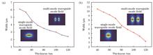
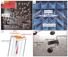
ObjectiveSensing technology based on Rydberg atoms overcomes the physical limitations of traditional electromagnetic sensing systems and offers many advantages such as small size, high sensitivity, and a broad measurement frequency range. The system typically requires two beams of light, with different wavelengths (such as 510 nm and 852 nm), transmitted in opposite directions to excite the atoms. Using optical fibers, rather than space optical links, to collimate and control dual-wavelength beams for constructing optical fiber-integrated atomic antenna probes is an effective method for practical application. However, collimated coupling elements are large and prone to scattering, which causes serious dispersion effects on dual-wavelength light with significant wavelength differences. In this study, a collimation metasurface with wavelengths of 510 nm and 852 nm was designed based on the working principle of achromatic metalenses. The simulation results indicate that the structure can achieve high efficiency and confocal collimation within the bandwidth of 500?1200 nm, which can enhance the coupling efficiency and level of miniaturization, thus promoting the practical development of portable atomic sensing probes.MethodsThe proposed structure is investigated using COMSOL Multiphysics software. Perfectly matched layers (PMLs) are employed along the incident direction to eliminate boundary scattering, and periodic boundary conditions (PBCs) are applied to the lateral boundaries of the unit cell. A cross-shaped dielectric column is selected as the phase-control unit structure to ensure effective total polarization control. Compared with conventional dielectric column structures, such as circular, elliptical, and rectangular, the cross-shaped structure offers more structural parameter variables, which can achieve a wider range of phase adjustment functions, and a single structure can meet the 0-π transmission phase requirements. The substrate is SiO2 with a refractive index of 1.47, and the dielectric column material is Si3N4 with a refractive index of approximately 2 at wavelengths of 510 nm and 852 nm. The period of the designed metasurface unit is 250 nm, with a height of 1300 nm, cross-arm length of 250 nm, and width of 90 nm.Results and DiscussionsThe dual-wavelength collimated metasurface structure was simulated. The focus for both wavelengths is set at F=20.0 μm, and the number of unit cells is N=21 in the x-direction. The distribution of the focused electric field is shown in Fig. 5(a). Theoretically, the beams of both wavelengths should focus at F=20.0 μm after passing through the metasurface. However, in the actual structure, due to a certain deviation between the simulated and theoretical phase values, the focal points for the wavelengths are at F=20.2 μm and F=17.5 μm, respectively. The focus of the 510 nm wavelength beam is almost the same as the theoretical value, while the focus of the 852 nm wavelength beam deviates by 2.5 μm. This deviation occurs because the optical aperture for the 852 nm wavelength beam is smaller than that for the 510 nm wavelength beam under the same metasurface size; hence, the focus deviation of the focusing field is larger, and its half-height full width becomes wider. The focusing error can be reduced by increasing the size of the optical aperture. Increasing the number of x-direction elements to N=27 and N=33 showed that the focus deviations decrease with an increase in the optical aperture, as illustrated in Figs. 6(a) and 6(b).ConclusionsTo address the issues of low efficiency and large volume in the dual-wavelength laser collimation module of a fiber-integrated Rydberg atomic electromagnetic sensing system, a collimated metasurface suitable for wavelengths of 510 nm and 852 nm was designed. The phase conditions for dual-wavelength confocal collimation were calculated using the metalens analysis method, and the values for dual-wavelength laser dispersion compensation were determined. A cross-shaped dielectric metasurface element was designed using a dielectric waveguide structure sensitive to geometric parameters. By varying the width of the cross-shaped structure from 150 nm to 30 nm, the transmission phase could cover 0 to π, and the average transmission amplitude exceeded 90%, meeting the design requirements for dual-wavelength arbitrary focal length collimating lenses. The average phase deviation of the designed metasurface was less than 10°, and the focal length deviation was less than 6%. The metasurface structure designed in this study supports highly sensitive and miniaturized Rydberg atomic electromagnetic sensing systems.
Nov. 15, 2024Vol. 51 Issue 22 2205001 (2024)
Yike Ren, Hui Shen, He Wang, Wei Xie, Yifeng Yang, and Yunfeng Qi
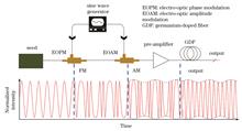
ObjectiveOwing to the high efficiency, excellent monochromaticity and beam quality, stable and reliable operation, and high environmental adaptability, high-power narrow-linewidth fiber lasers are widely applicable to various fields, such as spectral-beam combining (SBC), coherent-beam combining (CBC), nonlinear frequency conversion, remote-sensing measurement, and gravitational-wave detection. The development of application technologies has increased the demand for power scaling narrow-linewidth fiber lasers. To achieve prominent effects in SBC and CBC, a gigahertz spectral linewidth is typically required. Narrowing the linewidth and increasing the power simultaneously are challenging owing to nonlinear effects, in particular the stimulated Brillouin scattering (SBS) effect. To suppress SBS, researchers have proposed many methods, such as increasing the optical fiber-mode field area, reducing the optical-fiber length, optimizing the pump structure of the main amplifier, introducing gain competition, applying a temperature or stress gradient to broaden the Brillouin gain spectrum, and phase modulation. Among them, phase modulation can mitigate SBS by broadening the seed linewidth to effectively reduce the spectral power density of the laser; thus, it has been extensively investigated recently. However, improvement to the SBS threshold is limited under a certain linewidth. Nonlinear spectrum compression with a negative chirp is widely used in pulsed-fiber amplifiers. To reduce the SBS gain, the self-phase modulation (SPM) generated by the nonlinear Kerr effect is employed for phase demodulation and carrier recovery. Notably, this technique is applicable to continuous-wave laser domains. Multistage phase or frequency modulation (FM) is adopted to obtain a relatively wide spectrum and achieve a high-power output. Subsequently, the SPM generated in the fiber can be controlled via amplitude modulation (AM) to narrow the output spectrum. Consequently, power scaling with a narrow linewidth is achieved.MethodsIn this study, the principle of nonlinear phase demodulation based on SPM is investigated. The physical mechanism and factors affecting spectral compression are demonstrated comprehensively in a narrow-linewidth fiber laser with a broadened spectrum. The nonlinear demodulation of the spectrum is realized using combined modulation. When the modulation frequency is restricted to 10 GHz with general modulators, the effect of modulation on SBS is analyzed. The effect of phase error caused by FM and AM delays on the demodulation results is quantified to identify the optimal demodulation phase. In the case of optimal nonlinear demodulation, the relationship between the FM/AM depths and output power is investigated. The SBS thresholds under different modulations are compared experimentally. By combining this technique with phase modulation using a low-pass-filtered pseudo-random binary sequence (PRBS), one can overcome the current disadvantage of the phase-modulation technique and obtain fiber lasers with high powers.Results and DiscussionsIn the experiment, multistage modulations combining white noise source (WNS) modulation, FM, and AM are used to realize the nonlinear phase demodulation of the spectrum (Fig. 5). Signal-to-noise ratios of ±1-order sidebands and root-mean-square (RMS) linewidths are measured with different FM and AM phase shifts to evaluate the demodulating effect (Fig. 6). The optimal demodulation phase is obtained via theoretical simulation. In the case of perfect nonlinear phase demodulation, the FM depth is proportional to the output power, whereas the AM depth is inversely proportional to the power (Fig. 7), which is consistent with theory. The SBS thresholds under different modulation schemes are measured and compared experimentally (Fig. 8). The SBS threshold based on nonlinear phase demodulation is approximately twice higher than that based on pure phase modulation for the same linewidth (Table 1). By combining this technique with low-pass-filtered PRBS phase modulation, output spectrum compression is realized experimentally, and the linewidth reduces from 22.4 GHz (RMS) to 9.5 GHz (RMS) at an output power of 40 W (Fig. 9).ConclusionsIn this study, the physical mechanism and influencing factors of spectral linewidth compression based on the SPM effect are investigated comprehensively in narrow-linewidth fiber lasers via spectrum broadening. Nonlinear phase demodulation is realized by adopting the WNS modulation + FM + AM, and the effect of the demodulation phase is analyzed. The residual phase signal after nonlinear demodulation is an oscillating signal with the same frequency as that of the modulation signal, and the oscillating amplitude is proportional to βFM2-2cos Δ?. In the optimal demodulation phase, the relationship between the modulation depth and output laser power is measured, which shows consistency with theory. The SBS thresholds are measured and compared under different modulations. The SBS threshold spectral power density after the WNS modulation + FM + AM is higher than those after the WNS + FM. Compared with the case of pure phase modulation, the SBS threshold based on nonlinear phase demodulation is 2.4 times higher for the same linewidth. Additionally, the experimental results verify that the expected spectral compression can be achieved by combining PRBS signal modulation with a higher SBS threshold and nonlinear demodulation. A higher fiber-laser power can be obtained for the same linewidth via nonlinear demodulation, or the spectral linewidth can be reduced at the same output power. This approach can potentially overcome the limitation of the current phase-modulation technique and yield a higher power for a narrow-linewidth fiber laser. Additionally, it is advantageous for generating a higher spectral power density for pulsed or continuous-wave fiber amplifiers limited by SBS.
Nov. 15, 2024Vol. 51 Issue 22 2206004 (2024)
Zhicheng Jin, Shenhui Xue, Zhiyuan Xu, Fei Yang, Kang Ying, and Youzhen Gui
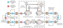
ObjectiveTo realize high-precision time-frequency transmission within a territory, the performance of ultra-long distance field links needs to be verified. In the case of the fiber time-frequency transmission of ultra-long links, optical power attenuation and cumulative phase noise increase with increasing link length, resulting in a decrease in compensation bandwidth and noise rejection ratio. Multi-stage cascade compensation is an effective solution, and introducing more cascaded transmission is the key to building a wide-area optical fiber time-frequency transmission network. For many applications that require a high time synchronization accuracy, it is necessary to know the exact delay value between the two sides to be synchronized while obtaining a stable time signal. Therefore, delay calibration and evaluation of the delay uncertainty of the optical fiber time-frequency transmission system are essential. This paper reports the realization of time-frequency cascade transmission and accurate delay calibration over a 515.66 km metro fiber link.MethodsA two-stage cascade design is adopted for the high-precision time-frequency simultaneous transmission system. The system is based on a dual-wavelength noise suppression scheme with optical compensation as the core, in which the time and frequency signals are co-transmitted by a wavelength division multiplexing (WDM) scheme. The structure and implementation of each level of synchronous transmission system are the same. Therefore, we consider the first level as an example. The 100 MHz frequency signal reaches 1 GHz frequency signal after 10 frequency doubling, and then is modulated by the light wave signal with wavelength of fiber channel C35 through the transmitter. The signal-to-noise ratio of transmission can be effectively improved by adopting a higher frequency. Concurrently, 1 PPS (pulse per second) time signal at the transmitting end is modulated by the optical wave signal of fiber channel C34 and entered into the optical fiber link using WDM technology. After reaching the receiving end, the frequency and time signals were obtained by demodulation of the detector output. The time-frequency signal is divided into two channels, with the frequency signal from one channel reduced by the frequency reducer to obtain a 100 MHz signal and the time signal reproduced to obtain a 1 PPS signal, output at the node as a time-frequency signal, which is input into the subsequent cascade system for transmission. The frequency signal from the other channel is modulated by the light wave signal of fiber channel C37, and the time signal is modulated by the light wave signal of fiber channel C36. The light wave signal is returned to the transmitting end through the same fiber link loop using WDM technology to suppress noise.Results and DiscussionsThe frequency instabilities at the user end with compensation are 6.49×10⁻¹⁴ at 1 s and 5.22×10⁻¹⁷ at 104 s on average. The time instabilities are 2.97×10⁻¹¹ at 1 s and 2.46×10⁻¹² at 400 s on average (Fig. 4). The discrepancy between the calibrated and measured values of the cascaded transmission delay for a 1 PPS signal in a 515.66 km field link is merely 29.90 ps (Table 2), whereas the uncertainty of unidirectional delay in the transmission link is 9.49 ps (Table 3). This demonstrates that achieving a time synchronization accuracy of better than 50.00 ps is feasible for a time-frequency transmission system over a field fiber link of more than 500 km. Consequently, this study presents an effective solution for accurate delay calibration and high-precision time synchronization in long-distance fiber optic links.ConclusionsIn this paper, we report the results of our work concerning high-precision frequency and time transfer in a partial Beijing-Langfang-Baoding optical fiber backbone network of 515.66 km using the cascaded method. Through optical compensation, transmission at each stage of the system is stabilized. The final additional frequency instability of the entire cascade system is 6.49×10⁻¹⁴ at 1 s and 5.22×10⁻¹⁷ at 104 s on average. The final time-attached instability is 2.97×10⁻¹¹ at 1 s and 2.46×10⁻¹² at 400 s on average. The difference between calibration and measured values for delay calibration of the cascade system is 29.90 ps. By analyzing the source of the uncertainty, the calculated uncertainty of the one-way transmission delay is 9.49 ps. Lossless transmission of high-precision time-frequency signals in long-distance commercial fiber optic networks and delay calibration of different stations in the network are realized. This lays a foundation for the future construction of ultra-long distance optical fiber time-frequency transmission networks and multi-point time synchronization. This research has important application prospects in the fields of large-scale atomic clock comparison and ultra-long baseline interferometry.
Nov. 15, 2024Vol. 51 Issue 22 2206005 (2024)
Lili Han, Fei Yang, Kang Cao, Huaguo Zang, and Weibiao Chen
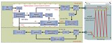
ObjectiveWith the gradual exploration and development of ocean resources, human efforts towards dynamic sensing, precise detection, information network construction, and data collection in marine environments will continue to expand, leading to a deeper understanding of the ocean. The marine spatiotemporal benchmark network is a common infrastructure for marine positioning and navigation systems, ocean environmental monitoring networks, and the Internet. Among these, underwater frequency transmission and synchronization constitute a crucial technological foundation for oceanic spatiotemporal benchmarks. With the advancements in science and technology, such as underwater observation networks, there is an increasing demand for higher precision in frequency transmission performance indicators.MethodsThis study proposes a high-precision underwater frequency transmission method for the blue-green laser based on digital phase compensation. Referring to the approach used in ground-based fiber optics, a dual-way time-frequency transmission is employed to enhance stability. Compared with the one-way transmission, the dual-way scheme allows for the signal returned from the remote end to be compared against the local reference signal, thereby improving the precision of the noise measurement. Using the blue-green laser as the carrier and digital phase compensation to enhance the frequency transmission noise compensation bandwidth, the method is experimentally verified with a 520 nm green laser diode, achieving bidirectional stable transmission of a 400 MHz frequency signal over an 8 m underwater link. A digital phase compensation system that included error signal acquisition, proportional-integral-derivative (PID) control, and digital phase shifting was established. Digital phase-shifting is applied to pre-compensate for additional phase fluctuations in the process of underwater frequency transmission to maintain the stability of the frequency of the underwater link. The experimental device for the underwater laser frequency transmission based on digital phase compensation is illustrated in Fig. 1, and the experimental setup is depicted in Fig. 2.Results and DiscussionsAccording to underwater frequency signal transmission noise performance characterization methods, the transmission performance of the frequency signal is tested in time and frequency domains. The experimental results presented for phase noise (Fig. 3), phase timing delay fluctuation (Fig. 4), and frequency stability (Fig. 5), demonstrate that the digital phase compensation technology can achieve a noise compensation bandwidth of 1 kHz, effectively suppressing noise fluctuations during a free-running operation within an offset frequency range of 1 kHz. The smaller the bias frequency, the more obvious the inhibition effect. Inhibition was 32.0 dB at 0.01 Hz and 15.4 dB at 1 Hz. attaining 2.5 dB at 1 kHz. Following the application of digital phase compensation, the frequency stability reached 7.9×10⁻¹⁴ at 1 s and improved to 2.1×10⁻¹⁶ at 1000 s. The frequency stability was improved by two orders of magnitude compared to that before digital phase compensation. The frequency stability attained an order of 10-14 for the first time. The phase-time delay fluctuation after phase compensation was also effectively suppressed, and the root mean square (RMS) of the phase-time delay fluctuation was 3.2 ps. These experimental results prove the feasibility of laser-based underwater frequency signal transmission using digital compensation technology with significantly improved stability of the frequency signal during underwater transmission. This indicates that digital technology, which facilitates system integration and miniaturization, has important application prospects in underwater navigation, timing synchronization, and construction of underwater spatiotemporal networks.ConclusionsThis study proposes the utilization of blue-green laser technology in conjunction with digital phase compensation techniques to achieve stable underwater transmission of frequency signals. Based on this methodology, a high-precision two-way transmission system was constructed for 400 MHz frequency signals over an 8 m underwater link. Experimental results demonstrate that the proposed digital compensation technology can achieve a compensation bandwidth of 1 kHz. Following compensation, the frequency stability reached 7.9×10⁻¹⁴ at 1 s, improving to 2.1×10⁻¹⁶ at 1000 s, significantly enhancing transmission accuracy. Furthermore, the digital phase compensation method exhibited excellent stability, facilitating the implementation in subsequent system engineering projects. This solution offers a new technical approach for underwater transmission and distribution of time-frequency references.
Nov. 25, 2024Vol. 51 Issue 22 2206006 (2024)
Jifeng Yao, Yumin Zhang, Yi Gao, Jing Tian, and Yanming Song
ObjectiveChirped fiber Bragg gratings (CFBGs), which feature a large dispersion range, low insertion loss, and variable positive and negative dispersions, are used as core devices in chirped pulse amplification systems to achieve high-power femtosecond pulses in fiber lasers. The spectral quality and intra-cavity dispersion compensation provided by small-dispersion CFBGs are related to the pulse width and quality of the femtosecond laser output. Achieving high reflectivity, spectral optimization, and accurate and effective dispersion measurements of CFBGs in a limit-length short grating length is key to the application of small-dispersion CFBGs to femtosecond laser oscillators. In this study, a method for the fabrication and measurement of small dispersions and large CFBGs is proposed. The fabrication of a small-dispersion CFBG with high reflectance and a flat reflection spectrum can be used to achieve the accurate dispersion matching of oscillator cavities in high-power femtosecond laser systems, which is of great significance for the performance improvement and development of fiber lasers.MethodsIn this study, a large chirped phase mask technology combined with high-order Gaussian apodization function and a refractive index modulation depth optimization method is used to fabricate a small dispersion CFBG, and the nonlinear curve fitting optimization method based on Michelson white light interference is used to achieve an accurate measurement of the dispersion.Results and DiscussionsFigure 3 shows the CFBG reflection spectrum obtained by simulating the effects of the grating area length, apodization function, and refractive index modulation depth on the reflection spectrum and adjusting the relationship among the three. According to the simulation results, when the CFBG chirp rate is determined, the change in the grating length changes the reflection spectrum bandwidth, different apodization functions affect the spectral shape, and the change in the refractive index modulation depth changes the reflectivity. Moreover, the CFBG is fabricated with a center wavelength of 1031 nm, bandwidth of 12 nm, and reflectivity of approximately 36.9%. Figure 4 shows the transmission and reflection spectra. Figure 5 shows the dispersion data processing method, and Fig. 5(c) shows the phase-fitting result extracted from the interference spectrum, with a correlation coefficient of 0.9999. The dispersion of the CFBG solved using the fitted phase is 1.1088 ps/nm at 1031 nm. Figure 6 shows the dispersion results and errors at different wavelengths, among which the standard deviation is the largest at 1027 nm, with a value of 0.00294. Figure 7(b) shows the influence of the different strengths of the two arms of the interferometer on the dispersion measurement results, and Fig. 8 shows the effect of the optical fiber connection loss in the dispersion measurement system on the dispersion measurement. The experimental results show that the strengths of the two arms of the interferometer as well as the optical fiber fusion connection loss influence the dispersion measurement experiment and that the dispersion value is more stable when the strengths of the two arms of the interferometer are close to each other.ConclusionsIn this study, a method for fabricating CFBGs based on a large-chirped phase mask combined with high-order Gaussian apodization function and refractive index modulation depth optimization is proposed. For a limited grating length, a small-dispersion CFBG with high reflectivity and spectral optimization is produced. A nonlinear curve-fitting optimization method based on Michelson white light interference is used to measure the dispersion. The experimental results demonstrate that the dispersion measurement method is accurate and effective. Small-dispersion CFBGs are expected to be used for the accurate dispersion matching of high-quality femtosecond fiber oscillators, which is of great significance for the improvement and development of fiber laser performance.
Nov. 11, 2024Vol. 51 Issue 22 2206007 (2024)
Mingjie Sun, Junchen Lin, and Hanye Yu
ObjectiveSpatial resolution is a key metric for evaluating the ability of an imaging system to resolve fine details and is a critical indicator of image quality. However, traditional imaging methods are constrained by the resolution limits of optical devices and the optical diffraction limit, often resulting in images that fail to meet high-resolution requirements. Consequently, a sustained effort has been conducted to overcome the diffraction limit in optical imaging. In the field of computational imaging, techniques such as compressed sensing, the design of specialized speckles, and subpixel sampling are commonly employed to achieve more stable and high-quality reconstructed images at low sampling rates. In this study, we proposed a computational ghost imaging resolution enhancement technique based on Zernike polynomial phase modulation. This method overcomes the resolution limits of traditional point scanning imaging systems. Our hope is that this research will inspire further studies aimed at overcoming the diffraction limits in computational imaging and that these concepts will be extended to a broader range of research in the field of imaging.MethodsThe basic structure of an imaging system was first designed, and a computational ghost imaging simulation was performed using LabVIEW. In the simulation, two methods of projecting masks, namely, point scanning and phase modulation based on the Zernike polynomial, were employed, and traditional (TGI) and orthogonalized (OGI) ghost imaging algorithms were used to reconstruct the edge image. The Zernike polynomial is a function used to describe the aberrations that occur in an optical system during imaging with lenses and other optical components. The masks generated based on the Zernike polynomial modulation form a set of non-orthogonal patterns, which necessitates that the corresponding OGI algorithm be used for image reconstruction. After the image was reconstructed, a quantitative analysis was conducted on the energy distribution of the masks and the quality of the reconstructed images to draw conclusions. Upon completion of the simulation, a physical imaging system was constructed based on the system design and simulation results. A computational ghost imaging experiment was conducted using point scanning and without applying any modulation to the spatial light modulator (SLM). The Zernike polynomial was then loaded onto the SLM to modulate the phase of the incident light, generating special mask patterns in the Fourier plane of the 4F system that were ultimately projected onto the object. A Siemens star and edge image were selected as the objects for image reconstruction to provide a more comprehensive comparison of the reconstruction quality. Finally, a quantitative analysis of the experimental results was performed to validate the conclusions of the simulation.Results and DiscussionsFigure 5 shows the modulation transfer function (MTF) of the simulation results based on the Zernike polynomial phase modulation and point scanning. The quality of the reconstructed images was evaluated using the area enclosed by the MTF curves, horizontal and vertical axes acted as indicators (Table 1). Results show that our method significantly outperforms traditional point-scanning imaging, and a potential correlation exists between the quality of the reconstructed images and the proportion of high-frequency light intensity in the corresponding masks. Specifically, a higher proportion of high-frequency light intensity in the mask directly corresponds to an enhancement of the resolution of the reconstructed image. In the experiments, image quality was compared in the same manner (Table 2). Experiments showed that our method consistently outperforms traditional point scanning imaging, successfully surpassing the resolution limits.ConclusionsIn this study, we proposed an image resolution enhancement method based on Zernike polynomial phase modulation. In the constructed computational ghost imaging system, the incident light was modulated using Zernike polynomials through a spatial light modulator (SLM) to generate special mask patterns in the far field. These mask patterns were projected onto an object, and the OGI algorithm was applied for image correlation to achieve image reconstruction. The resolution of the reconstructed image surpasses that of traditional point scanning results, achieving enhanced resolution at a reduced time cost. This method successfully overcomes the spatial resolution limits imposed by the SLM aperture in point scanning. In addition, a quantitative analysis of the relationship between the proportion of high-frequency light intensity in the mask patterns and the image resolution was conducted to explore the mechanism behind the resolution enhancement achieved by this system. The feasibility of this method for overcoming the resolution limits in computational imaging was also explored. In the future, experimentations with more Zernike polynomials to adjust the high-frequency light intensity proportion can be expected to further improve image resolution. In addition, because the peak intensity of the mask patterns irradiating an object is relatively low, this method can avoid sample damage, making it promising for applications in the field of microscopy to achieve super-resolution imaging.
Nov. 17, 2024Vol. 51 Issue 22 2209001 (2024)
Jingwei Zhang, Jingpei Hu, Mengjie Sun, Jiahao Hu, Aijun Zeng, and Huijie Huang
ObjectiveAs a critical resolution enhancement method, source and mask optimization (SMO) technology significantly improves imaging quality and process window performance by optimizing the source shape and mask pattern simultaneously through multiple iterations. The existing approaches for implementing optimized illumination modes with high degrees of freedom are typically based on two methods: the diffractive optical element (DOE) and the micromirror array (MMA). The limitations of the DOE-based method include the inflexibility of the illumination modes and partial energy loss. The MMA-based method can flexibly achieve arbitrary source shapes by modulating the tilt angles of the thousands of micromirrors. However, current MMA manufacturing faces challenges for the large-scale integration of micromirrors. Existing two-dimensional (2D) mirrors mainly rely on external movable frames and multiple electrodes, which complicate the manufacture of the MMA. In this study, we report a 2D micromirror mechanical structure with a single serpentine beam and two fixed electrodes. We also propose an optimized electrode structure to reduce the driving voltage. We believe that the designed micromirror array has great potential for application in illumination systems.MethodsIn this study, a 2D micromirror machine with a serpentine beam is designed. A movable plate is supported by the beam fixed to an anchor on the substrate. The micromirror surface is coated with the high reflective layer of a 193 nm laser to reduce the energy loss in the lithography system. Two symmetrically distributed electrode structures are placed below the movable plate. The micromirror employs a serpentine beam as the mechanical force driving part, which is actuated by the electrostatic force between the fixed electrodes and movable plate. The driving process of the micromirror is sequentially simulated and analyzed. Subsequently, a stepped electrode structure is designed to reduce the driving voltage. In addition, based on the established mechanical model of the micromirror, the voltage–displacement tilt curves of the initial and optimized electrode structures are obtained through multi-physical field coupling simulation analysis.Results and DiscussionsBy using different electrode configurations, the designed micromirror can achieve three operating conditions (Table 5). Therefore, the micromirror can achieve a 2D tilt with only two fixed electrodes, which significantly simplifies the driving module of the micromirror array. Under Con. 3 condition, when the bias voltage applied to the driving electrodes reaches approximately 55 V, the maximum tilt angle reaches 26.2 mrad.Compared with the initial driving electrode structure with the maximum tilt angle of 17.8 mrad, the corresponding pull-down displacement of the moving plate is increased by 46.6% (Fig. 8), effectively reducing the driving voltage during micromirror operation. The stress distributions of the two different electrode structures are obtained through simulations (Fig. 9).ConclusionsIn this study, an effective micromirror composed of a movable plate, two fixed electrodes, and a serpentine beam is proposed. The designed micromirror eliminates the need for external movable frame configurations, effectively simplifying the mirror structure. In addition, a stepped electrode structure is proposed. When a voltage of 55 V is applied to both electrodes, the maximum tilt angle reaches 26.2 mrad.Compared with the initial driving electrode structure with the maximum tilt angle of 17.8 mrad, the corresponding pull-down displacement of the moving plate is increased by 46.6%. This micromirror structure, which simplifies the driving module and reduces the driving voltage, has great potential for applications in illumination systems.
Nov. 14, 2024Vol. 51 Issue 22 2201003 (2024)
Yuanhao Mao, Zhongqi Tan, Dingbo Chen, Qiucheng Gong, Bin Zhang, Suyong Wu, Jianping Liu, Zhenfang Fan, Hui Luo, and Xingwu Long
ObjectiveIndependent, all-weather, and high-frequency universal time measurement is crucial for establishing a comprehensive national time-monitoring system in China. This system is vital for supporting major strategic tasks such as manned spaceflight and deep-space exploration. Large-ring laser gyroscopes, which are anchored to the Earth bedrock, provide direct acquisition of signals related to the Earth rotation and are vital to universal time measurement.MethodsTo balance the angular precision and dimensions of a large-ring laser resonator, an optical-contacted laser resonator is initially designed, which comprises a central block, four extension blocks, a gain block, and four quartz tubes. Subsequently, the cavity ring-down method is utilized to measure the losses of the fundamental transverse mode (TEM00) and high-order transverse modes to validate the rationality of the aperture design. The finite-element method is employed to simulate the laser plasma dynamics process, where the optimal He/Ne particle number ratio is obtained. By adjusting the gas pressure and pump current, a stable single longitudinal mode and the Earth rotation signal are achieved using the NUDT-MRLG550 laser gyroscope.Results and DiscussionsThis study introduces China first large-ring laser gyroscope named NUDT-MRLG550, which is based on Zerodur glass. The gyroscope utilizes an optical-adhesive combination scheme and has a side length of 0.55 m (Fig. 1). It features a direct-current (DC) discharge gain length of 60 mm and a capillary diameter of 6 mm. The loss difference between TEM00 and high-order transverse mode (TEM01) is 78×10-6, with a 3.24-mm-diameter diaphragm located at the beam waist (Fig. 2). Based on theoretical and experimental investigations on laser plasma dynamics, an optimal He/Ne particle number ratio of 25∶1 is obtained (Fig. 3), in addition to a stable output under a single longitudinal mode with a power of 4 μW and the TEM00 (Fig. 4). Observations conducted at 28°N latitude successfully detect stable Earth rotation signals at a frequency of 29.6 Hz.ConclusionsThe design process of the first Chinese Zerodur-based large-ring laser gyroscope, NUDT-MRLG550, is presented comprehensively herein. A new design and manufacturing solution for large-ring laser gyroscopes is provided, thus addressing the technological gap in this field in China. The NUDT-MRLG550 is a two-frequency laser gyroscope with the smallest lock-in region reported thus far (the lock-in threshold is less than 30 Hz), which can compress the size of the two-frequency laser gyroscope unlocked by Earth rotation to 0.55 m×0.55 m, i.e., only one-half the size of the first-generation large laser gyroscope, C-II. Owing to its smaller size, the NUDT-MRLG550 offers the highest output power (~4 μW) in a single longitudinal mode compared with all large laser gyroscopes currently in operation. Specifically, its output power is three orders of magnitude higher than those of its counterparts, which effectively reduces the quantum noise generated. The theoretical random walk limit of the NUDT-MRLG550 is 1.6×10⁻⁹ rad·s-1/2.
Nov. 14, 2024Vol. 51 Issue 22 2201004 (2024)
Nan Li, Haizhou Huang, Fei Shi, Wen Weng, Jinhui Li, Huagang Liu, and Wenxiong Lin
ObjectiveHo-doped gain media, which feature absorption and emission transition between manifolds 5I8 and 5I7, have longer lasing wavelengths (2 μm) and larger emission cross-sections than Tm-doped gain media. Thus, Ho lasers are more advantageous in various applications such as mid-infrared nonlinear frequency generation, photo-electronic countermeasures, medical treatment, and laser-range identification. However, high power Ho lasers with high slope efficiencies (SEs) can be obtained by in-band pumping 1.9 μm Tm laser sources. Nonetheless, the required system is large and expensive, which renders it impractical and inaccessible in many applications. In this study, an efficient Ho∶YAP laser pumped with a composite Tm∶YAG slab laser intra-cavity is demonstrated. The results provide an effective scheme to directly use typical laser diodes (LDs) to achieve a compact, accessible, linearly-polarized 2.1 μm laser at room temperature.MethodsA fiber-coupled 785 nm LD, with a core diameter of 400 μm and a numerical aperture (NA) of 0.22, is used as a pump source to pump the absorption peak of a Tm∶YAG crystal. Plano-convex lenses F1 and F2, which feature identical focal lengths of 40 mm, are utilized to collimate and focus the pump light into a spot with a diameter of 380 μm within the Tm∶YAG crystal. Additionally, a Tm∶YAG crystal with a cross-section measuring 1.5 mm×6.0 mm and a length of 17 mm is applied. As more severe thermal effects occur in the Tm-doped gain medium during intra-cavity pumping, the pump end of the Tm∶YAG crystal is diffusion boned with another 3 mm long YAG slice to alleviate the thermal effects. Two Ho∶YAP crystals measuring 3 mm×3 mm×7 mm are applied, which are cut along the crystallographic a- and c-axes, to compare the Ho laser performance. A 42-mm-long plano-concave resonator is developed for intra-cavity pumping. The beam quality is evaluated using a pyroelectric camera, and the laser wavelength is measured using a spectral analyzer.Results and DiscussionsEfficient Tm laser operation with a maximum output power of 18.62 W is obtained with an SE of 49.82%, which corresponds to an optical conversion efficiency (OE) of 46.8% [Fig. 2(a)]. Using the a-cut Ho∶YAP crystal, a lower output power of 9.48 W at 2118.5 nm (E∥c) with an SE of 26.1% and an OE of 23% is obtained [Fig. 4(a)]. Based on Fig. 3, the laser wavelength for the a-cut Ho∶YAP laser is 2118.5 nm [measured at an output power of 9.48 W, Fig. 5(a)], with the polarization direction being parallel to the crystallographic c-axis. At the maximum Ho laser power, the beam quality is measured and fitted with beam quality factors of 1.81 and 1.94 along the transverse and vertical directions, respectively [Fig. 5(b)]. A maximum Ho laser power of 12.07 W at 2129 nm (E∥b) is obtained using the c-cut Ho∶YAP crystal, with an SE of 32.2% and an OE of 28.7% [Fig. 6(a)]. At the maximum output power of 12.07 W, the laser wavelength is measured to be 2129.61 nm [E∥b, with a polarized extinction ratio of 18.3 dB, Fig. 7(a)], and the beam quality is measured and fitted with beam quality factors of 3.56 and 3.23 in the transverse and vertical directions, respectively [Fig. 7(b)]. Considering the maximum incident pump power of 42 W, the OEs for the current a- and c-cut Ho∶YAP lasers are 23.04% and 28.7%, respectively. This is because the intra-cavity absorptions for both Ho∶YAP crystals at 2022 nm are almost identical [Fig. 3(b)]. This difference in lasing efficiency is attributable to the cavity loss. By expanding the absorption spectra of the Ho∶YAP crystal at its lasing band (Fig. 8), we discover an absorption peak at approximately 2117 nm for the polarization along the c-axis, which results in a higher cavity loss for the a-cut Ho∶YAP laser. By contrast, no absorption peak is observed along the c-axis at approximately 2129.6 nm for the c-cut Ho∶YAP crystal. However, the c-cut Ho∶YAP laser, which shares the same crystallographic b-axis with the a-cut Ho∶YAP laser and exhibits a lower thermal conductivity along the a-axis [11.6 W/(m-1·K-1)] than along the c-axis [12.3 W/(m-1·K-1)] , shows worse beam quality.ConclusionsA composite Tm∶YAG slab laser intra-cavity pumped Ho∶YAP laser with superior linearly polarized operation compared with YAG-based intra-cavity pumped lasers is presented. Maximum output power levels of 9.48 W at 2118.5 nm (E∥c) and 12.07 W at 2129.6 nm (E∥b) are obtained from a- and c-cut Ho∶YAP lasers respectively, with corresponding SEs of 26.1% and 32.2% and OEs of 23% and 28.7%, respectively. The lower lasing efficiencies of the a-cut Ho∶YAP laser is attributed to the presence of a re-absorption peak along the crystallographic a-axis at 2117 nm. The results provide a direct diode-pumped, linearly polarized Ho laser scheme with a compact structure, where higher lasing power is limited by the available incident LD power, thus obviating the necessity to develop another high-power 1.9 μm laser source for in-band pumping.
Nov. 25, 2024Vol. 51 Issue 22 2201005 (2024)
Junyan Chen, Hongwei Zang, Jincheng Cao, Yao Fu, Helong Li, Zhensheng Tao, and Huailiang Xu
ObjectiveIntense few-cycle laser pulses are particularly important for applications in strong-field physics, time-resolved spectroscopy, and nonlinear optics. However, generating ultrastable, high-efficiency few-cycle pulses with high beam quality is challenging. In this study, we demonstrate our achievement of compressing a 50 fs Ti∶sapphire laser pulse at a wavelength of 800 nm to ~11.8 fs. This corresponds to four to five optical cycles via ultrastable solitary propagation in a periodic layered Kerr medium (PLKM) in ambient air, which results in a broadband supercontinuum spectrum from visible to infrared in the range of 598 nm to 945 nm with a conversion efficiency of ~92%. By comprehensively investigating the effects of various experimental parameters on the temporal and spatial modes of the output pulses, we reveal the formation conditions for discrete spatiotemporal solitons.MethodsWe utilize linearly polarized, 800 nm, 50 fs Ti∶sapphire laser pulses as the driving source, whose laser energy can be controlled using a half-wave plate (HWP) and a thin-film polarizer. A plano-convex lens with a focal length f1=200 cm is used to focus the laser pulses in ambient air. The PLKM comprises 10 pieces of 200-μm-thick fused silica plates, which are placed in parallel with the laser incident angle at the Brewster angle (55.5°). The spacing L between two adjacent plates can be adjusted along the laser-propagation direction using a linear track. The first PLKM plate is placed immediately after the focal spot of the laser beam. The laser pulses resulting from the PLKM are collimated using a concave mirror with a focal length f2=100 cm and then compressed using four pairs of chirped mirrors and a pair of wedges. The laser pulse energy is determined from the laser power measured using a thermopile detector, and the output-beam profiles are characterized by measuring the laser spot on a paper using a commercial camera, where the distance between the final plate and paper is maintained at 300 mm. To perform spectral measurements, an integrating sphere is used to obtain the laser signal, which is then detected using a fiber-coupled spectrometer. The temporal profiles of the laser pulses are measured using a custom-developed second-harmonic-generation frequency-resolved optical gating (SHG-FROG) and then reconstructed using principal component generalized projections (PCGPs).Results and DiscussionsBased on Eqs. (1), (2), and (3) and the experimental conditions shown in Fig. 1, we obtain the initial distance for the PLKM to form a quasi-soliton and then generate the supercontinuum spectra and beam patterns, as shown in Fig. 2. By monitoring the variations in the beam modes and the spectra of the output pulses after the PLKM under several different spacing distances L, we discover that under an input laser energy of 350 μJ, the 800 nm, 50 fs laser pulses result in effective spectrum broadening with a favorable beam mode only at a specific spacing distance of L=100 mm, in which the self-focusing and diffraction effects are well balanced [Figs. 2(a) and (b)], thus resulting in the highest output energy [Fig. 2(c)]. To further optimize soliton generation by the PLKM, we observe the variations in the laser spectra and beam patterns of the output laser pulses by adjusting the input laser energy from 320 μJ and 370 μJ under L=100 mm. Based on Fig. 3, as the input laser energy varies, the broadened spectra remain almost constant but the beam modes change significantly. Specifically, the beam size reaches the minimum when the input pulse energy is 340 μJ [Figs. 3(a) and (b)], and the shortest pulse duration (~52 fs) is recorded. This is consistent with the pulse duration (50 fs) of the input pulses [Fig. 3(c)]. The stable spatial and temporal profiles provide evidence of soliton formation. Consequently, after the PLKM, an excellent discrete spatiotemporal soliton laser pulse with an energy of 312 μJ is obtained, with the broad spectrum encompassing 598 nm to 945 nm at -20 dB. The soliton pulse is then compressed to ~11.8 fs using four pairs of chirp mirrors and a pair of wedges, which corresponds to four to five optical cycles (Fig. 4).ConclusionsWe demonstrate the robust generation of intense few-cycle pulses with a broad spectrum ranging from visible to near infrared using a commercial Ti∶sapphire femtosecond laser system and a PLKM. By focusing 340 μJ, 50 fs, 800 nm pulses into a single-stage PLKM, which is composed of 10 pieces of 200-μm-thick fused silica plates with an equal spacing distance L=100 mm, excellent discrete spatiotemporal solitons ranging from 598 nm to 945 nm at -20 dB and an energy of 312 μJ are obtained. Few-cycle (11.8 fs) pulses are achieved unambiguously when the soliton pulse is compressed using a pair of wedges and four pairs of chirped mirrors. Our results provide a new method for generating high-quality, high-efficiency few-cycle pulses using a Ti∶sapphire femtosecond laser.
Nov. 14, 2024Vol. 51 Issue 22 2201006 (2024)
Wendi Wu, Peigao Han, and Rende Ma
ObjectiveIn modern applications of polarized optical technology, linear and circular polarizations are the predominant types of polarized light. The transformation between these two forms of polarized light requires the use of optical phase retarders. Zero-order waveplates measure only a few tens of micrometers thick, and high precision is required during their production to achieve such thickness, which poses considerable fabrication challenges. This study introduces an innovative design for a binary composite-structure waveplate using two quartz crystals of equal thickness. By customizing the optical axis angle of one crystal, a zero-order phase delay can be achieved for a designated light wavelength. This novel zero-order waveplate structure can effectively mitigate the effects of thickness variations on the phase delay of the output light during the manufacturing process.MethodsThe proposed zero-order waveplate features a binary structure with equal-thickness components comprising two parallel crystal plates fabricated using identical birefringent materials, each with thickness d, bonded together (Fig. 1). We define a coordinate system, as shown in Fig. 1(a), where the bonding interface of the two crystal plates is aligned with the yoz plane. Figure 1(b) shows a cross-sectional view of the device. The optical axis of the crystal on the left side of the xoy plane, denoted as crystal 1, lies within the xoy plane and is perpendicular to the xoz plane. Meanwhile, the optical axis of the crystal on the right side, denoted as crystal 2, is within the xoy plane and forms an angle γ with the x-axis while maintaining a thickness equal to that of crystal 1. The phase delay of light incident on this binary structure can be fine-tuned by adjusting the optical axis angle of crystal 2, thus resulting in a smaller phase delay for a specific light wavelength. The differential phase delay is quantified as shown in Eq. (8). A zero-order phase delay of 1/4 wavelength corresponds to a specific relationship among the optical axis angle of crystal 2, the crystal thickness, and the light wavelength, as expressed in Eq. (9).Results and DiscussionsBy applying Eqs. (8) and (9), we can ascertain the design parameters for a zero-order waveplate with a equal-thickness binary structure suitable for any uniaxial birefringent crystal. Our investigation into the spectral characteristics, thickness variations, deviations in the optical axis angle, as well as the effect of temperature fluctuations on the phase delay using optical quartz crystals shows that the equal-thickness binary structure waveplate possesses achromatic qualities similar to those of conventional zero-order waveplates. Additionally, it indicates that a phase-delay deviation owing to thickness inconsistencies is less than 1.3% of that observed in conventional zero-order waveplates. Moreover, the phase-delay variations remain within ±0.1° for temperature shifts of ±10 °C, which is smaller than the corresponding variation in conventional zero-order waveplates. Notably, the accuracy of phase delay for our waveplate design is primarily affected by the precision of the optical axis angle of crystal 2. We constructed two samples with different wavelengths using an optical quartz crystal as the base material and performed spectral phase-delay testing using a polarimeter via a transmission method. The experimental results (Figs. 6 and 7) confirm that the observed phase-delay variation across the wavelengths is consistent with theoretical predictions, with the polarimeter measurements of the device’s phase-delay deviations being less than 0.5°.ConclusionsThis paper presents a novel equal-thickness binary structure design for a zero-order waveplate. Based on the light-propagation properties of uniaxial crystals, we developed a universal design formula that delineates the relationship among the optical axis angle of crystal 2, the intended wavelength, the desired delay, and the thickness of an individual crystal. Our analysis shows that the equal-thickness binary structure zero-order waveplate is comparable to classical designs in terms of optical performance and is affected less by temperature and thickness variations. In conclusion, the innovative equal-thickness binary structure zero-order waveplate successfully minimizes the effects of manufacturing inaccuracies on the phase delay accuracy, thereby offering considerable practical advantages.
Nov. 17, 2024Vol. 51 Issue 22 2201007 (2024)
Jianhao Tang, Xiaoqi Zhang, Yanli Zhang, Guowen Zhang, Ruifeng Wang, Ziang Chen, and Jianqiang Zhu
ObjectiveFor a multi-transverse mode-stabilized cavity, the transverse modes can be written as an incoherent superposition of Hermite?Gaussian (HG) beams. The modal weights, λmn, can completely characterize the light field of partially coherent beams, and the CSD (cross spectral density) of the beam at any position in space can be evaluated using the modal weights as well as any global beam parameter such as beam quantity factor M2. The problem involves determining the weights of the underlying modes based on experimentally determined quantities. Various methods such as coherence measurements and best-fitting procedures have been proposed to address this problem. In many applications, such as material processing and speckle reduction, uniformity of the laser power distribution on the beam cross and low spatial coherence are desired qualities, and the model of circular flat-topped intensity distributions for partially coherent beams (FTIPCBs) is useful. Determining the modal weights of a circular FTIPCB in a simple manner and exploring the characteristics of the circular FTIPCB are important.MethodsIn this study, an analytical algorithm for recovering modal weights was extended from one-dimensional flat-topped intensity distribution beams to a circular FTIPCB. The beam quality factor M2 of the circular FTIPCB was evaluated in two-dimensions using model weights to investigate the relationship between beam quality factor M2 and light field order N. The coherence function of uniformly correlated partially coherent beams with the same near- and far-field intensity distributions as those of the circular FTIPCB was calculated based on the transmission function of the partially coherent beams. The coherence function of the circular FTIPCB was then compared with that of the uniformly correlated partially coherent beams, leading to the following conclusion.Results and DiscussionsWe provided an equation for circular flat-topped intensity distributions and cross-sectional one-dimensional light intensity curves (Fig. 1). A numerical deduction process was presented for the modal weights of the circular FTIPCB. Considering N=16 and w0=4 mm as an example, normalized modal weights λmn were provided (Fig. 2). The near-field light intensity distribution, INF, and far-field light intensity distribution, IFF, were calculated using the mode weights shown in Fig. 2 and the Collins formula (Fig. 3). Beam quality factor in x direction, Mx2, was calculated for various values of light field order N, and the data were fitted to determine the relationship between Mx2 and N in the circular FTIPCB. The coherence functions of the circular FTIPCB were calculated using three starting points at different positions (Fig. 4). We constructed a uniformly correlated partially coherent beam with the same near- and far-field intensity distributions as those of the circular FTIPCB. The coherence functions of the uniformly correlated partially coherent beams were calculated based on the transmission functions of the partially coherent beams (Fig. 4). Compared with the coherence function of the circular FTIPCB, the results indicate that the spatial coherence length of the uniformly correlated partially coherent beams is longer than that of the round FTIPCB.ConclusionsIn this study, we determine the modal weights of a circular FTIPCB and evaluated various properties of the circular FTIPCB based on the modal weights. For the circular FTIPCB, the intermediate modes have a larger weight, and the lower- and higher-order modes have smaller weights; this is considerably different from the mode weight distribution of the one-dimensional FTIPCB. The relationship between Mx2 and N in the circular FTIPCB differs significantly from that in a one-dimensional FTIPCB. The shape of the light intensity distribution and the order, N, determine the mode weights that, in turn, determine beam quality factor M2; therefore, the relationship between beam quality factor M2 and N changes as the overall shape of the light intensity distribution changes. The circular FTIPCB maintains a flat-topped distribution after transmission to the far field, maintaining the same shape as that of the near field. The coherence function of the circular FTIPCB changes when the position changes, revealing that the circular FTIPCB is nonuniformly correlated. Based on equation (13), notably, coherence function μ is determined by mutual intensity Jr1, r2 and the light intensity. In the top region where the light intensity is constant, μ=Jr1, r2. Jr1, r2 is determined by both ?mnr and λmn. As ?mnr is a function of the position, Jr1, r2 is also a function of the position. However, in special cases such as the Gaussian Schell model, special mode weights λmn cause the coherence function to become uncorrelated with position. Because of the transmission properties of Hermite?Gaussian beams, when the circular FTIPCB is linearly transmitted to any position, only the beam width changes, leading to changes in the spatial coherence length, and the shape and mode weights of the beam do not change; therefore, the spatial coherence of the beam must be characterized by beam quality factor M2. A clear relationship should exist between the spatial coherence length of the circular FTIPCB and the beam half-width and the beam quality factor M2. Notably, the simulation results indicate that the round FTIPCB has a shorter spatial coherence length than the uniformly correlated partially coherent beams with the same near- and far-field intensities.
Nov. 17, 2024Vol. 51 Issue 22 2201008 (2024)
Ya Xu, Xi Chen, Mingjian Wang, Bo Dai, Jiqiao Liu, Zhenzhen Yu, Xia Hou, and Weibiao Chen
ObjectiveDeep-space exploration typically refers to the exploration of the moon and other extraterrestrial bodies. It is integral to space activities and allows humans to further understand the universe as well as explore the origin and evolution of matter and life. For deep-space detection, laser detection is used extensively as it offers good direction and strong anti-interference ability. In addition to offering high-precision detection, space lasers should be small and lightweight such that power consumption can be reduced and reliability can be increased. In deep-space exploration, the laser-detection load is limited primarily by volume, weight, and power consumption, thus necessitating micro laser devices. In this study, a small and lightweight passive Q-switched all-solid-state laser for deep-space exploration is introduced, and its prototype is developed. The laser output features a high repetition frequency, narrow pulse width, and high pulse energy. Additionally, the laser prototype is small, lightweight, and highly reliable, thus rendering it an ideal light source for deep-space exploration.MethodsTo achieve a small and lightweight laser structure, passive Q-switching was performed. By selecting Nd∶YAG as the gain medium and Cr∶YAG as the passive Q-switched crystal, the gain medium and passive Q-switched crystal were bonded to achieve an integrated resonator, which can not only miniaturize the laser structure but also form a short cavity structure to achieve a narrow pulse-width output. The laser was pumped using two single-tube COS (chip on submount) pulsed semiconductor lasers with a pulse repetition rate of 1 kHz and a central wavelength of 808 nm. The two semiconductor lasers were connected in series, which can significantly reduce the operating current of the pumped semiconductor laser and improve the reliability of the system. The temperature was precisely controlled via a TEC (thermo-electric cooler) to ensure the absorption efficiency of the pump light. The pumped LD (laser diode) output laser was collimated by fast- and slow-axis collimators and was focused into the laser gain medium through the focusing mirror. The fast-axis collimator is an aspherical cylindrical lens, whereas the slow-axis collimator is a flat convex cylindrical lens. The crystal was coated to form a resonator with a flat cavity structure and a physical cavity length of 11 mm. The 808 nm LD adopts the COS package and integrates the pumping LD with a laser optical-path structure, thereby affording laser integration and improving the reliability of the laser. COS packaging technology offers high integration and high reliability, thus rendering it suitable for space solid-state lasers with miniaturization and long-life requirements.Results and DiscussionsUnder a pumping optical power of 2.16 W, a laser output with a monopulse energy of 172 μJ and a repetition frequency of 1 kHz is obtained. The laser output frequency is shown in Figure 5. Additionally, the laser was tested. Figure 6 shows the stability monitoring of the monopulse energy for a week. The mean value of the monopulse energy output by the laser is 172 μJ, and the standard deviation is 1.96 μJ. The root-mean-square of the monopulse-energy instability for one week is 1.1%. The obtained pulse waveform is shown in Figure 7. As shown, the pulse waveform is smooth and the pulse width is approximately 1.0 ns. The laser-beam quality factors are Mx2 =1.35 and My2 =1.27, as shown in Figure 8. The weight of the laser head, as measured using a balance, is 176.9 g (see Figure 9).ConclusionsIn this study, a small and lightweight passive Q-switched all-solid-state laser for deep-space exploration was introduced, and its prototype was developed. A Nd∶YAG/Cr∶YAG bonded crystal pumped using a laser diode was used to achieve a 1064 nm laser output. At the operating frequency of 1 kHz, the pulse width is 1.0 ns, the single-pulse energy is 172 μJ, and the single-pulse energy instability is 1.1%. The beam quality factors are Mx2=1.35 and My2=1.27. The COS packaging process was adopted for the machine, and the internal components and shell of the laser were welded with metal only. The size of the laser is 76.44 mm×49.58 mm×19.23 mm, which signifies a miniaturized laser; additionally, the weight of the laser is only 176.9 g. Thus, the laser is small, lightweight, and highly reliable, which renders it suitable as an ideal light source for deep-space exploration.
Nov. 17, 2024Vol. 51 Issue 22 2201009 (2024)
Jinghong Ning, Luyao Sun, Qingyu Zhang, Ziliang Ren, Zhipeng Song, and Sen Zhu
ObjectiveTo meet the market demand, the performance of semiconductor lasers is continuously improving. In the digital era, the increasing integration of various electronic components is leading to a rapid increase in power densities and operating temperatures. During normal operations, approximately 40%?60% of the optical energy is converted into heat energy that is stored within the laser. The performances of semiconductor lasers are closely related to their thermal management. Research has shown that under adequate cooling conditions (the ideal state), significant enhancements can be achieved in terms of the emission efficiency, output power, beam quality, temperature stability, and reliability. The traditional cooling media for semiconductor lasers include R32, water, and liquid nitrogen, which dissipate heat under certain conditions. However, with a continuous increase in the laser heat flux density, traditional cooling media exhibit significant limitations. Carbon dioxide, which is a non-polar molecule with a simple structure, exists as a colorless and odorless gas in liquid and solid forms. When throttled to reduce the pressure to atmospheric levels, liquid carbon dioxide transforms into solid dry ice at extremely low temperatures. This study introduces dry ice as a cooling medium and proposes a novel array nozzle device. Combining jet impingement with dry ice phase-change cooling enables the efficient thermal management of high-heat flux density semiconductor lasers.MethodsThis study focused on practical stacked high-power semiconductor lasers. Initially, an array nozzle device utilizing dry ice cooling was designed based on the dry ice particle formation mechanism. The device primarily comprises jetting chambers, array nozzles, and simulated laser heat sources. During the modeling, a uniform arrangement with equal spacing and size in a parallel layout between the array nozzles and laser heat sources was adopted. The array nozzle configuration was 3×4 with a Laval nozzle consisting of a converging section, throat, and diverging section. Subsequently, computational fluid dynamics (CFD) software was employed to simulate the heat exchange process. For the sublimation heat transfer of dry ice and the two-phase flow heat transfer process, user-defined functions (UDF) were employed for the numerical simulation, thereby enabling the determination of the optimal nozzle parameters by varying the throat diameter of the Laval array nozzle and adjusting the spray height. These parameters were then applied to investigate the cooling characteristics of lasers with different heat flux densities using a relatively optimal nozzle configuration. Finally, through experimental validation and comparison with numerical simulation results, minor experimental errors were obtained, ensuring the feasibility of using Laval array nozzles for the dry ice cooling of high heat flux density semiconductor lasers.Results and DiscussionsThe physical model of the Laval array nozzle dry ice sublimation heat transfer established in this study was used to analyze the influence of the throat diameter on the temperature uniformity of the laser and its cooling effect in local regions. The throat diameter affects the exit velocity, direction, and mass flow rate of the dry ice particle spray, thereby affecting the heat transfer effectiveness of dry ice particle spray cooling. When the throat diameter is <4 mm, the temperature distribution at the impact position of the Laval array nozzle exhibits a ring shape. The interference between the nozzle outlet velocities decreases, resulting in lower temperatures closer to the center, whereas relatively higher temperatures occur in the edge and gap areas outside the region directly facing the jet impact. When the throat diameter is <4 mm, the temperature of local high-temperature region largely remains within the safe operating range of the laser (Fig. 2). At a spray height of 15 mm, there is a significant increase in the proportion of the high-temperature regions of the heat source. For lasers with heat flux densities below 100 W/cm2, it is advisable to maintain the spray height within a range of 10?15 mm (Fig. 5). The temperatures at measurement points along the laser length at x=-10 mm, x=0 mm, and x=10 mm show minimal variation at heights of H=15?25 mm (Fig. 6). Utilizing the relatively optimal nozzle configuration for cooling different heat flux density lasers, spray heights of H=5 mm, 8 mm, and 10 mm can ensure that the temperatures of semiconductor lasers with heat flux densities of 165 W/cm2, 156 W/cm2, and 125 W/cm2 do not exceed 40 ℃, with a heat transfer coefficient reaching up to 20113.47 W/(m2·K). This configuration guarantees the normal operation of kilowatt-level high-power semiconductor lasers (Fig. 7).ConclusionsBased on the Laval array nozzle dry ice particle sublimation cooling model, numerical simulations and experimental studies are conducted on the heat dissipation process of the laser. The research reveals that under the same heat flux density, a smaller throat diameter results in a higher spray outlet velocity, which leads to a lower average temperature and better temperature uniformity of the laser. With the same throat diameter, as the spray height decreases, the proportion of the low-temperature area increases, with a heat transfer coefficient of 19516 W/(m2·K) at 5?10 mm. As the heat flux density increases under the same spray height conditions, the temperature of the laser increases linearly. The array nozzle meets the requirements for the normal operation of lasers within 180 W/m2, with a heat transfer coefficient of 20470.82 W/(m2·K).
Nov. 17, 2024Vol. 51 Issue 22 2201010 (2024)
Ziang Chen, Xiaoqi Zhang, Yanli Zhang, Jianhao Tang, Ruifeng Wang, and Jianqiang Zhu
ObjectiveIn recent years, a variety of coherent beam smoothing technologies, including temporal and spatial smoothing, have been developed to control the spatiotemporal characteristics of focal spots, which have helped reduce the Rayleigh-Taylor instability generated by laser plasma in the process of inertial confinement fusion. Spatial smoothing technologies, such as continuous phase plates (CPP) and lens arrays (LA), along with temporal smoothing technologies, such as induced spatial incoherence (ISI) technology and smoothing by spectral dispersion (SSD) have been widely used in large scientific devices. Considering coherent beam-smoothing technologies, we explored the feasibility of partially coherent beam smoothing. The high fill factor of a multi-transverse mode-flattened Gaussian partially coherent beam (MPCB) is conducive to energy storage extraction from the laser medium and often used in high-power laser systems. Thus, the technical route of MPCB smoothing is of great significance, as discussed in this paper, in analyzing the relationship between the integration time and focal spot of MPCB passing through a CPP designed for coherent beam smoothing. The relationship between the spatial coherence of MPCB and the smoothing effect and profile of the focal spot are also reported.MethodsIn this study, a one-dimensional MPCB is constructed through an incoherent superposition of Hermite?Gaussian (HG) modes. This is easily extendable to a two-dimensional MPCB, using an analytical algorithm that recovers the modal weights (Fig. 1). The spatial coherence of the MPCB at any position in space can be evaluated by the modal weights and is determined by the light field order N, representing the number of HG modes involved in the superposition. The larger the N, the lower the spatial coherence of MPCB. Two different spatial coherences of MPCBs are established, with N values of 22 and 46. The CPP designed for coherent beam smoothing is calculated using the Gerchberg-Saxton algorithm. The differences in the focal spots of the coherent beam and MPCBs passing through the CPP are compared (Fig. 2). The parameters η and R90 show the profile of focal spots, whereas FOPAI5 and δRMS indicate the smoothing effect of focal spots. Additionally, the power spectral density (PSD) is also calculated to verify that the mid-frequency of focal spots (10?100 μm) is suppressed.Results and DiscussionsFigure 2 clearly demonstrates that focal spot distributions depend on the relationship between integration time t and coherence time tc. HG modes interfere coherently to generate a speckle pattern on a timescale of t<tc, whereas HG modes are mostly uncorrelated with one another and interfere incoherently to generate a relatively more uniform pattern on a timescale of t>tc. The spatial coherences of MPCBs and CPP are shown in Figs. 3?4, respectively. The focal spots of the coherent beam and MPCBs share a similar profile [Fig. 5(a)]. The parameter η of each focal spot is a little different and over 98%. Similarly, the parameter R90 of a focal spot is hardly distinguishable from that of another and does not exceed 254.4 μm. In detail. the focal spots of MPCBs feature a larger contour profile. When N is 22 and 46, the δRMS parameters of the focal spot of MPCB were 5.26% and 4.75%, respectively, with a 40 μm filter, whereas that of the coherent beam was 5.75% with the same filter, which suggests that focal spots of MPCBs are more uniform than that of coherent beam. The higher the order N of MPCB, the lower the spatial coherence of MPCB, and the smaller the δRMS, the more uniform the focal spot [Fig. 5(b)]. However, FOPAI5 implies nonuniformity of the focal spots of the MPCBs on a timescale of t<tc. Correspondingly, the PSD revealed that the midfrequency of the focal spots of the MPCBs is not well suppressed on a timescale of t<tc [Fig. 5(c)].ConclusionsIn this paper, we propose a technical approach for MPCB smoothing using CPP, explaining the principle based on the characteristics of MPCB. The focal spot of the MPCB and that of a coherent beam passing through the same CPP were compared. The results show that on a timescale of t>tc, the focal spot of the MPCB can be reshaped by the CPP and basically coincides with that of the coherent beam. The spatial coherence of the MPCB had little impact on the focal spot profile. The smoothing effect of the focal spot of the MPCB was always better than that of the coherent beam with the same filter. The lower the spatial coherence of the MPCB, the more uniform the focal spot. For N over 46, the focal spot of MPCB is expected to achieve δRMS<4%. On a timescale of t<tc, the problems of FOPAI5 and PSD of the MPCB focal spot can be solved by shortening the coherence time and increasing the beam bandwidth. The focal spot of the MPCB would be much more uniform if MPCB smoothing were combined with other beam-smoothing technologies.
Nov. 15, 2024Vol. 51 Issue 22 2201011 (2024)
Bowei Yang, Yunfeng Wu, Yanrong Song, and Zhigang Zhang
ObjectiveHigh-pulse energy femtosecond lasers with high repetition rates are required in numerous areas such as high-field physics, high-energy terahertz pulse generation, high-fluence attosecond pulse generation, and material processing. Femtosecond pulses with energies above millijoules are generally achieved using solid-state lasers. Heat-related problems limit solid-state laser operation at high average powers. By contrast, fiber lasers are attractive owing to their compactness, flexibility, and low cost. However, the pulse energy of the fiber lasers is limited by their nonlinearity and optical damage. Coherent stacking of numerous femtosecond pulses is a promising technique for generating high pulse energy at a high repetition rate. Temporal stacking can be achieved using cavity stacking, delay-line stacking, or a hybrid of the two. Delay line stacking uses pulses with a repetition rate of 80?100 MHz, corresponding to a pulse separation of 12.5?10.0 ns, or several delay lines with the lengths of multiple times of 3.75?3.00 m for stacking, which makes the system bulky and unstable.MethodsWe propose and demonstrate that with a 1 GHz repetition rate pulse train, the delay lines can be significantly shortened so that more pulses can be stacked in a compact structure. The system includes a 1 GHz repetition rate femtosecond fiber laser, a chirped fiber Bragg grating (CFBG) as a stretcher, four fiber amplifiers in series, eight delay line stages, and a grating compressor. The pulses experience intensity modulation that chops the pulse train into bursts of 128 pulses using an electro-optical modulator (EOM). Then, the 128 pulses are stretched using a CFBG and split into two branches. Two EOMs are inserted into each branch to modulate the phases of individual pulses. The phase modulations in 0 or π are added to individual pulses such that after each stacking, the pulse train maintains two polarizations with neighbor pulses that are crossly polarized. In the stacking stage, the first delay line is used to compensate for the path difference in the amplification stages. Then, the remaining seven stages of the delay lines are used to compensate for the time delay between pulses. The stacking strategy used is pulse-train folding. The next stacking stage folds the 128 pulses in the burst into 64 pulses, and the folding process continues until only one pulse remains. A set of control FPGA software and hardware is employed to maintain the stability of the delay lines.Results and DiscussionsThe final amplification delivers a 10 kHz burst train with an average power of 2 W. The energy of each pulse during a burst is 780 nJ. After stacking and compression, the pulse energy of the stacked 256 pulses becomes 100.5 μJ, with a pulse width of 437 fs. The average power of the combined pulse train is stabilized within a fluctuation of 0.45%. The stacking efficiency is 56%. The low stacking efficiency is attributed to the contrast and transmission of the polarization beam splitters.ConclusionsA coherent stacking of 256 femtosecond pulses is shown from a burst of a 1 GHz pulse train. Although the pulse energy is not high, the stacking technique has the potential to stack a few hundred mJ femtosecond pulses and is expected to find broad applications.
Nov. 19, 2024Vol. 51 Issue 22 2201012 (2024)
Ao Li, Qiang Yuan, Chao Yang, Yong Chen, Licheng Zhu, Shiqing Ma, Hongwei Ye, Shuai Wang, Zeyu Gao, and Ping Yang
ObjectiveThe Shack-Hartmann wavefront sensor (SHWFS) has been widely used to measure wavefronts; however, its dynamic range and measurement accuracy limit its application. The SHWFS primarily comprises a microlens array and a charge-coupled device (CCD). The dynamic range of the SHWFS depends on the ratio of the maximum allowable offset of the focal spot to the focal length of the microlens because the focal spot generated by each microlens must be located in a predefined sub-aperture region on the detector. In this study, a method based on the Sobel operator and a floating sub-aperture spot-matching algorithm is proposed to solve the problem where the focal spot of the SHWFS exceeds its corresponding sub-aperture owing to large wavefront distortions or pupil tilts.MethodsIn this study, a wavefront-reconstruction algorithm for enlarging the dynamic range of the SHWFS is proposed. First, a centroid-estimation algorithm based on the Sobel operator was used to calculate the coordinate positions of all focal spots from an entire spot-array image. This addresses the limitation of the conventional algorithm, in that the spot centroid must be extracted within the sub-aperture range. The focal spots were segmented using the Sobel edge-extraction algorithm, and the centroid of the segmented focal spot region was calculated. Additionally, because centroid extraction was only performed in the focal spot region, a high-precision centroid-extraction algorithm was used. After extracting the centroids of all spots, a spot-matching algorithm based on a floating sub-aperture was established to match the extracted spot centroids with the corresponding sub-apertures. By combining the two algorithms, a wavefront-reconstruction algorithm for a large-dynamic-range SHWFS was established.Results and DiscussionsThe centroid-calculation area of the algorithm proposed in this study is only within the ranges of threshold (Fig. 3) and speck-region-connected domain segmentations (Fig. 4); therefore, the effect of noise is eliminated. When the incident beam features a large oblique aberration, the position of the spot on the CCD is shifted, thus causing the captured spot to be outside the corresponding sub-aperture region. The corresponding relationship between the centroid of the focal spot and the reference centroid was established using the proposed algorithm (Fig. 6), and the focal spot was matched to the corresponding sub-aperture (Fig. 7), thus further expanding the dynamic range of the SHWFS. The performance of the algorithm was analyzed via numerical simulation, where the incident wavefront shows a large tilt and high-order aberration (the RMS and PV values are 4.71λ and 21.76λ, respectively). Additionally, the performance of the proposed algorithm was quantitatively analyzed via numerical simulation (Fig. 9). Compared with the case of the conventional algorithm, the dynamic range of the proposed algorithm is 1.14 to 4.85 times higher.ConclusionsIn this study, a wavefront-reconstruction algorithm for a Shack-Hartmann wavefront sensor with a large dynamic range is proposed, which overcomes the limitation of the conventional algorithm, in that the centroid of the spot must be extracted within the sub-aperture range. Because the centroid-calculation region of the proposed algorithm is only within the spot region of the threshold and connected-domain segmentations, the effect of noise is eliminated. By matching the spot with the sub-aperture based on the floating sub-aperture spot-matching algorithm, the dynamic range is further extended by 1.14 to 4.85 times. The performance of the algorithm was analyzed through numerical simulations, and the effectiveness of the algorithm was further verified experimentally.
Nov. 25, 2024Vol. 51 Issue 22 2204001 (2024)
Yinlong Xian, Zhiyu Zhu, and Dongbing He
ObjectiveTerahertz metalenses have broad prospects in the future; however, currently, common metalens preparation methods such as lithography, electron beam lithography (EBL), and focused ion beam (FIB) usually require the use of a photoresist, which is cumbersome. Using photothermo-refractive (PTR) glass as a substrate eliminates the need for a photoresist during the preparation process. PTR glass is a UV-sensitive silicate glass material doped with photosensitive elements, such as Ce, Ag, and Sn. After UV exposure and thermal treatment, small NaF microcrystals precipitate. Owing to the different etching rates of hydrofluoric acid on the PTR glass substrate and NaF microcrystals, selective exposure of the area to be etched can be achieved, resulting in the desired groove structure. To obtain a complete metalens unit structure, metal thin films can be prepared in the grooves using methods such as evaporation, magnetron sputtering, atomic layer deposition, and chemical vapor deposition. To verify whether PTR glass can be applied to metalenses, THz metalenses are designed using PTR glass as a substrate.MethodsWe measure and analyze the absorption coefficient and refractive index of PTR glass in the terahertz band by scanning its terahertz transmission spectrum (Fig. 2) and obtain the relative dielectric constant of the material. A cell simulation model is constructed in COMSOL at a working frequency of 0.4 THz [Fig. 3(a)], and the cell structure is simulated to obtain the cell transmittance and phase.Results and DiscussionsUsing the control-variable method, we simulate the ring width, opening angle, and rotation angle of the resonant ring, obtaining nine structures (Table 1). According to Formula (5), we arrange the units to obtain metalenses with focal lengths of 3000, 5000, 8000, and 10000 μm with numerical apertures of 0.6042, 0.4819, 0.3960, and 0.3593, respectively. After analyzing the electric-field intensity of the metalens (Fig. 5), we obtain the normalized electric-field intensity along the x-direction at the focus (Fig. 6). We calculate that the focusing efficiencies of these metalenses are 22.89%, 16.223%, 15.58%, and 17.51%, respectively, which are higher than those of metal-structured metalenses using other substrates.ConclusionsBased on transmission and Panchaiatnam-Berry (PB) phase theories, we design nine types of metalens units with PTR glass as the substrate, resulting in nine types of metalens units. At a frequency of 0.4 THz, the phase can change from 0 to 2π, and the transmittance is stably higher than 0.27. At the same time, by arranging the units, terahertz metalenses with focal points of 3000, 5000, 8000, and 10000 μm are designed. The focusing efficiency of this structure can be higher than 15% with good focusing performance. The possibility of preparing metalenses using PTR glass as the substrate is verified through simulations. An alternative method for preparing metalenses without using a photoresist is found, which is expected to reduce the manufacturing cost in the future metalens industry and provide a new development direction for materials with photothermal sensitivity, such as PTR glass.
Nov. 19, 2024Vol. 51 Issue 22 2213001 (2024)
Qian Sun, Hongbo Liu, Yunhao Zhang, Kui Liu, and Jiangrui Gao
ObjectiveAs a crucial quantum light source, the squeezed state of light plays a pivotal role in advancing quantum information, quantum networks, quantum computing, and quantum-precision measurements. The emergence of optical frequency combs is of great significance in the field of precision measurements and offers a novel avenue for achieving high-precision and long-distance measurements. The optical frequency comb represents a new class of light sources characterized by periodic ultrashort pulses, resulting in a spectrum with equally spaced frequencies. Based on the special properties of the optical frequency comb, researchers applied it to the quantum field, obtaining the “quantum frequency comb,” which is a new quantum resource contributing to the development of the quantum field. The generation of a femtosecond squeezed state in an optical field is challenging because of the extended cavity and optical path of the resonator. Compared with continuous waves, femtosecond pulses are more sensitive to external noise, posing difficulties in achieving a stable squeezed state. This limitation hinders the practical application of femtosecond squeezed light in quantum information protocols. Thus, achieving a long-term stable femtosecond pulse-squeezed state of the light field is considered a fundamental requirement.MethodsA titanium sapphire laser is used to generate pulsed light with a central wavelength of 850 nm, pulse width of 130 fs, and pulse repetition rate of 76 MHz. A femtosecond pulse-squeezed vacuum state of the light field is obtained without signal injection based on a synchronously pumped optical parametric oscillator below the threshold. Nevertheless, the primary hurdle is the effective suppression of noise through the implementation of phase-locking between the signal and local components. To address this, the relative phase between the pump and local field is locked to suppress the phase noise. A bismuth borate (BIBO) nonlinear crystal with a thickness of 2 mm is used to generate the second harmonic. The second harmonic light generated by the pump is interference-locked with the pump. The interference signal is segmented into two paths and subtracted using a half-wave plate and polarization beam splitter (PBS) to improve the signal-to-noise ratio. Finally, the error signal is directed toward the proportion integration differentiation (PID) controller, which drives the piezoelectric ceramic in the local field. This achieves effective phase synchronization between the local field and pump. This synchronization locks the experimental light path before the 50/50 beam splitter. By improving the relative phase stability of the beams, a long-term stable femtosecond pulse-squeezed vacuum state of light is achieved. The degree of phase drift of the squeezed light is measured and analyzed for both the locked and unlocked phase loops.Results and DiscussionsIn the absence of locked phase loops, the measured squeezed vacuum noise fluctuates significantly owing to external factors. Long-term monitoring reveals a large left-right drift in the power spectrum line of the squeezed vacuum noise, with a phase jitter range of 0.507 rad (Fig. 2). After locking the relative phase between the local field and pump, the stability of the system improves. The stability of the noise power spectrum of the squeezed light is significantly enhanced compared with that of the unlocked situation (Fig. 6). Simultaneously, the left-right drift at the squeezed light in both cases is analyzed, and data points are extracted and plotted in a scatter plot. The standard deviation of the two sets of data reflects the degree of phase jitter. The analysis results show that the random phase jitter is suppressed by 68.05% during the experiment (Fig. 7). Finally, the noise signals in both cases are smoothed. Under long-term measurement, the long-term squeezing degree increases from 0.6 dB to 3.2 dB, effectively inhibiting random phase jitter and improving the quality and accuracy of squeeze test results (Fig. 8).ConclusionsBased on a synchronously pumped optical parametric oscillator below the threshold, a femtosecond pulse-squeezed vacuum state of the light field is obtained without signal field injection. This study successfully achieves a long-term stable output of squeezed vacuum state of femtosecond pulse through a scheme of frequency multiplication of local light and interference locking of frequency multiplication light with the pump. The experimental results demonstrate the successful suppression of 68.05% of the stochastic phase jitter during the squeezing measurement process, leading to an increase in the squeezing degree from 0.6 dB to 3.2 dB. Thus, the stability of the system is significantly enhanced. This methodology addresses the challenges associated with femtosecond pulses, paving the way for advancements in quantum technology.
Nov. 11, 2024Vol. 51 Issue 22 2212001 (2024)
Linxiong Wen, Yi Tan, Ping Yang, and Wang Zhao
ObjectiveTarget wavefront detection with variable scalability is a technical challenge for adaptive optics applications in object identification, laser atmospheric transmission, laser communication, object imaging, and other fields. In engineering applications within these fields, the phase information of an aberrated wavefront is measured in real time using a correlated Hartmann wavefront sensor. This sensor contributes to excellent wavefront correction in adaptive optics systems, which can lead to imaging quality optimization and beam quality enhancement. As the “eye” of an adaptive optics system, the detection accuracy of the wavefront sensor directly affects the correction capability of the adaptive optics. Hartmann wavefront detection of extended objects often involves the use of the cross-correlation function to estimate the peak value to obtain the sub-aperture offset and then recover the wavefront phase. When the detector is operated, owing to the real-time change in the motion state of the extended object itself and the influence of atmospheric turbulence, the image of the extended object of the sub-aperture object surface often exhibits various types of quality degradation, such as image contrast change, spot drift, and spot dispersion. The flicker phenomenon most often occurs on the edge sub-aperture, which directly leads to the partial loss of the sub-aperture image, thus affecting the calculation of the sub-aperture offset by the relevant algorithm and reducing the accuracy of wavefront detection. In this paper, we report on the sub-aperture and reference images required by an image preprocessing algorithm. After processing, the calculation accuracy of the sub-aperture offset is greatly improved. Under different missing degrees of the image, the preprocessing method exhibits stability, and the wavefront detection accuracy is improved accordingly.MethodsIn this study, the speeded-up robust feature (SURF) feature-matching image preprocessing method is used. Before the cross-correlation calculation of the sub-aperture offset, the reference image near the central position of the selected sub-aperture imaging quality and the sub-aperture image under test are used as the feature-matching image pairs. For feature extraction, description, and matching, the pixel unit block with the highest matching degree is selected, that is, the pixel unit block with the shortest Euclidean distance, and the remaining image parts are set to zero and deleted as a new input image pair for cross-correlation calculation. The offset to each sub-aperture is calculated, and the slope matrix of the entire sub-aperture is calculated with the extracted calibrated reference position. Subsequently, the mature Zernike mode method is used to reconstruct the wavefront to be measured, and the wavefront detection process is completed.Results and DiscussionsThe influence of different missing degrees of the sub-aperture image of the extended object on wavefront recovery is analyzed, and a quantitative description of the degree of expansion is provided. The influence of partially missing degrees of the sub-aperture image on wavefront detection accuracy under different expansion degrees, sub-aperture resolutions, and signal-to-noise ratios is investigated, and a detection method based on SURF feature-matching preprocessing is proposed. With an increase in the partial missing degree of the sub-aperture image, the error of the slope extraction result from the cross-correlation algorithm increases, and the system wavefront detection accuracy decreases. Slope extraction after SURF feature-matching preprocessing is significantly improved but limited by the sub-aperture resolution of the detection system; the lower the resolution, the worse the improvement effect. It is also affected by the system noise; when the signal-to-noise ratio is too low, there is a mismatching pair, resulting in a larger error on the slope extraction. Under the same degree of missing image, the greater the degree of expansion, the lower the object detection accuracy. Compared with the case in which the sub-aperture image is less missing, SURF feature-matching preprocessing can be performed after improving the sub-aperture resolution to compensate for the slope extraction error caused by the loss. The wavefront to be measured can then be restored, thereby improving the detection effect of the adaptive optics (AO) system.ConclusionsIn this study, a numerical model of correlated Hartmann wavefront detection for extended objects in the case of partial loss of the sub-aperture image is established. The degree of expansion of an extended object is quantitatively described, and the influence of the degree of sub-aperture image loss on slope extraction and the detection accuracy of the correlated Hartmann wavefront is analyzed. A detection method based on SURF feature-matching preprocessing is proposed. The simulation results show that the slope extraction error caused by partial loss of the sub-aperture image of a reasonable extended object can be reduced by 66%. The peak-to-valley and root mean square values of wavefront restoration residuals are reduced, and the detection accuracy of the adaptive optical wavefront is significantly improved. The results provide a reference for the design of the Hartmann sensor. In the future, experimental research will be conducted using the object characteristic of the non-cooperative variable-extension degree of motion. Moreover, image enhancement technology will be further studied when the sub-aperture imaging part of the target is missing in the case of strong scintillation, to improve the Hartmann wavefront sensing ability.
Nov. 13, 2024Vol. 51 Issue 22 2210001 (2024)
Jingmin Tu, Yang Shen, Jie Li, Mingming Li, Li Li, and Jian Yao
ObjectiveThe roof plane is a fundamental element in urban building structures. The precise segmentation of building roofs is crucial for reconstructing 3D models based on laser point cloud data. Currently, roof plane segmentation is mainly achieved by using point cloud plane segmentation algorithms, which can be divided into two categories: point-based and voxel-based methods. Point-based methods are not limited by shape and density and have strong applicability and high robustness; however, their segmentation accuracy depends on the feature estimation accuracy. Although voxel-based algorithms can calculate features more accurately and efficiently, they are more sensitive to the voxel grid size. The roof plane types of urban buildings include but are not limited to arched, sloping, and folded roofs. Diverse shapes and uneven distributions are major challenges for precise roof plane segmentation, which is one of the main reasons for over- and under-segmentation. Irrelevant patches generated by oversegmentation and unclear planar boundaries caused by undersegmentation lead to unsatisfactory segmentation accuracy. Accordingly, we propose a novel airborne LiDAR point cloud roof plane segmentation method based on voxel and point hybrid growth. The advantages of our method are as follows: 1) a more accurate feature estimation, 2) the reduced generation of pseudoplanes at the boundaries, and 3) an effective allocation of plane intersection points. The experimental results demonstrate the validity of the proposed approach. We hope that this project can provide a new idea for 3D point cloud data processing and analysis as well as provide technical support for many tasks, such as urban surveying and planning and high-precision urban 3D model reconstruction.MethodsRoof-plane segmentation is a crucial step in the 3D reconstruction of buildings. In this study, we propose a novel airborne LiDAR point cloud roof plane segmentation algorithm based on voxel and point hybrid growth. The proposed approach comprises three parts (Fig. 1). In the first part, voxels are separated into planar and non-planar voxels via an octree structure, and the feature information is then calculated for each planar voxel. In the second part, we design a plane coarse segmentation based on the voxel and point hybrid growth. Continuity, coplanarity, and distance features are the main constraints in the growth stage for obtaining the initial planar patches. Finally, in the third part, fine plane segmentation based on the cumulative distance voting mechanism is proposed to redistribute the unallocated points. The final segmentation results can be obtained by using a simple merging operation, according to the continuity and coplanarity constraints.Results and DiscussionsThis study proposes a novel voxel and point hybrid growth algorithm for roof plane segmentation. The proposed method has three advantages. 1) Our approach uses voxels as the minimum feature computation unit. Hence, it can obtain more precise normal and curvature information, compared with point-based methods. As shown in Fig. 4, larger voxels are mostly found in smooth regions, whereas smaller voxels are found at the edges, corners, or around the rough regions. This implies that local surface planarity can be represented well by smaller voxels in the margins. 2) We design the residual value and point cloud number of voxels as criteria for the seed voxels, which not only solves the problem of the improper selection of seed voxels but also avoids the generation of pseudoplanes at the boundaries. 3) A novel voxel and point hybrid growth mechanism is proposed to allocate points at the plane junction, which can reduce the impact of voxel size changes. A reasonable allocation of boundary points can also yield better segmentation results. The experimental results (Figs. 15 and 16) indicate that the proposed method performs well for diverse roof-plane segmentations. In particular, for roofs with multiple planes, our method can also distinguish boundaries effectively and obtain high accuracy (Table 2), compared with other state-of-the-art approaches (Figs. 17 and 18).ConclusionsIn this study, we present a novel approach for roof-plane segmentation from airborne LiDAR point clouds. The proposed voxel and point hybrid growth algorithm can accurately calculate the feature information and reasonably assign boundary points. First, the voxels are separated via an octree structure, which can distinguish the voxels at the junctions of planes to accommodate local planarity. Second, we employ continuity, coplanarity, and distance constraints in a voxel and point hybrid region growth model to acquire the initial planar patches. Finally, a cumulative distance voting mechanism is used to reassign unsegmented points to improve the accuracy. The segmentation results are obtained after a simple merging operation. The experimental results prove that the aforementioned algorithms are valid and feasible. Compared with the traditional RANSAC, region growth, and EVBS methods, the proposed approach appears to have more advantages in complex roof plane segmentation. Finally, our study can be used for 3D model reconstruction, urban surveying, and planning.
Nov. 17, 2024Vol. 51 Issue 22 2210002 (2024)
Juan Chen, Hongjuan Zhang, Pengfei Wang, Yan Gao, and Baoquan Jin
ObjectivePhase-sensitive optical time-domain reflectometry (Φ-OTDR), owing to its unique advantages in the sensor domain, has received significant attention. Among the pivotal advancements in this field, the introduction of frequency-division multiplexing (FDM) is notable as it significantly enhances the system’s frequency-response bandwidth and overcomes the limitations imposed by the fiber length on the maximum response frequency. This breakthrough has considerably expanded the utility of FDM Φ-OTDR, particularly in applications requiring high-frequency vibration monitoring and ultrasonic sensing for partial-discharge detection. However, the practical deployment of FDM Φ-OTDR systems is typically accompanied by substantial challenges, including interference from external environmental factors and phase noise from the light source, which severely compromises the accuracy of high-frequency detection. Addressing these issues is critical for the advancement and broader application of Φ-OTDR. Previous attempts to mitigate noise interference, such as wavelet denoising and variational-mode decomposition, indicate limitations, including dependence on base functions and the inability to achieve a satisfactory signal-to-noise ratio (SNR) in nonstationary environments. This study proposes an innovative approach, i.e., an improved singular value decomposition (SVD) method for noise reduction, which addresses the specific challenges encountered by FDM Φ-OTDR systems in high-frequency signal detection. By constructing a Hankel singular-value matrix to distinguish between signal and noise components and employing a thresholding method to identify significant singular values, this method not only effectively suppresses noise but also preserves essential high-frequency information. This study aims to provide a novel perspective and a robust solution for noise suppression in FDM Φ-OTDR systems, thus enhancing their performance in critical applications such as infrastructure monitoring and the diagnosis of electrical-cable faults.MethodsIn this study, the operational principles and demodulation process of an FDM Φ-OTDR system are presented, along with the introduction of an improved SVD methodology for noise suppression within the functioning framework of the sensor. The principle of the noise-reduction technique is the strategic selection of a threshold, as depicted in Fig. 5, where each frequency signal yields a pair of closely matched singular values following SVD. These pairs serve as the foundation for establishing equivalence between the frequency differential outcomes and singular values, which is crucial for effective noise mitigation. The proposed method begins with the demodulation of high-frequency signals via the FDM Φ-OTDR system, followed by the transformation of these signals into a Hankel-matrix configuration. This transformation facilitates the differentiation between the primary-signal components and secondary-noise elements within the signal matrix. By employing a thresholding approach, we delineate the principal singular values, which are instrumental to noise reduction while preserving essential high-frequency details. This procedure involves: 1) band-pass filtering to segregate Rayleigh backscattering (RBS) light from various channels and performing alignment to form a three-dimensional RBS matrix; 2) orthogonally demodulating RBS light from different channels to extract phase components followed by concatenating these components based on their sensing sequence to achieve phase restoration; 3) employing the Hankel matrix to execute SVD, thereby isolating noisy singular values; 4) utilizing established formulas to select an optimal threshold, thus nullifying noise-related singular values; 5) reconstructing data with the refined singular-value matrix, which culminates in noise attenuation in the high-frequency signals. This comprehensive approach underpins our improved SVD-based noise-suppression strategy, thus offering a new perspective and solution for high-frequency signal monitoring in FDM Φ-OTDR systems.Results and DiscussionsAn FDM Φ-OTDR system as an acoustic or vibrational sensor was developed and implemented in this study, which achieved a maximum responsive frequency-band range of 62.5 kHz. As shown in Fig. 7, this system accurately reconstructs sinusoidal vibrations at 25.0 kHz, thereby highlighting its proficiency in discerning external disturbances. Subsequently, the system was employed to detect subtle acoustic signals using an improved SVD method for the precise reconstruction of nonstationary sound signals ranging from 0 to 3.5 kHz. Initial experiments validated the accuracy and reliability of the system for vibration and acoustic-signal detection, along with the feasibility of the enhanced SVD method for noise suppression. Further application of the improved SVD method to the system facilitated the detection of partial-discharge signals. The construction of the Hankel matrix for denoising, as shown in Fig. 11, coupled with the power differential spectrum depicted in Fig. 12, enabled the elimination of periodic narrowbands and white noise in partial-discharge signals. A comparative analysis of the wavelet-threshold-denoising and variational-mode decomposition methods demonstrates the superior denoising capability of the improved SVD approach. As indicated in Table 1, after denoising, the waveform similarity of the effective partial-discharge signal reaches 0.963, with the root-mean-square error reducing to 0.0099, and the SNR increasing from 13.118 dB to 29.300 dB, i.e., an increase by 16.182 dB in the SNR. This signifies a significant advancement in noise suppression and signal clarity for FDM Φ-OTDR systems.ConclusionsThis study introduces an improved SVD denoising method devised for suppressing background noise in high-frequency signal detection using FDM Φ-OTDR systems. By deconstructing the Hankel singular-value matrix and employing a threshold method to discern significant singular values, the method effectively distinguishes between primary and secondary noise elements, thus facilitating noise-component elimination. Empirical validation of the FDM Φ-OTDR system shows a broad frequency-response range, which signifies its ability to detect high frequencies. The system adeptly identifies nonstationary acoustic signals within the 0?3.5 kHz range in environmental settings, thus ultimately achieving the detection and denoising of partial-discharge signals in 10 kV power cables. Compared with the original signals, the denoised signals exhibit a waveform similarity of 0.963, with a lower root-mean-square error of 0.0099 and an improved SNR of 16.182 dB. The proposed method not only expands the measurable frequency response of FDM Φ-OTDR systems to 62.5 kHz, thus significantly enhancing the frequency-response range of distributed fiber-optic sensors, but also signifies a novel and meaningful attempt in monitoring nonstationary acoustic and partial-discharge signals. This approach provides a new perspective and solution for high-frequency signal monitoring within FDM Φ-OTDR systems, thus expanding the boundaries of current applications and inspiring further innovations in the field.
Nov. 18, 2024Vol. 51 Issue 22 2210003 (2024)
Xingpeng Yan, Haiyang Yu, Hanyu Li, and Xunbo Yu
SignificanceOver the past century, the quest to replicate three-dimensional visuals as they appear in the real world has driven significant innovations in display technology, with light-field displays at the forefront. These systems not only capture the complexity of light behavior in three-dimensional spaces but also allow this complexity to be presented in a manner that human eyes naturally understand, without the need for additional equipment such as glasses or headsets. This capability marks a substantial leap from traditional two-dimensional displays, setting the stage for revolution in the consumption and interaction of visual content. Light-field technology leverages various light modulation and generation techniques to create vivid life-like images. From the inception of basic light field concepts to the development of sophisticated systems that manipulate photons to mimic real-world visuals, this technology promises a transformative impact on all forms of digital displays.ProgressThe development of light-field display technology has undergone numerous iterations and innovations that can be broadly categorized into several types of systems, each with unique mechanisms for light manipulation and display capabilities. For instance, integral imaging and lenticular displays use lens arrays to capture and reproduce light fields that allow viewers to view different parts of an image from different angles, thereby simulating a true 3D effect. This method has evolved significantly since its conceptual introduction by Gabriel Lippmann in 1908, with advancements in digital imaging and processing technologies that have enhanced its viability and effectiveness.Integral-imaging 3D displays have evolved continually, improving the resolution, depth accuracy, and real-time data processing. These advancements have been driven by enhancements in both hardware capabilities and computational techniques, making the technology more practical for applications requiring high-fidelity and dynamic 3D content.Grating-type 3D displays have undergone substantial enhancements in recent years. Innovations have focused on optimizing the diffraction grating elements to reduce crosstalk and improve image clarity and resolution. Hybrid grating systems that combine multiple types of optical gratings have been developed to refine the light field distribution, thereby expanding the viewing angle and enriching the depth perception of the displayed images.Projection-based light-field systems represent another innovative approach that employs arrays of projectors to illuminate scenes and reconstruct light fields in real time. These systems have grown increasingly complex, with current configurations capable of displaying crisp, seamless images across large viewing angles without crosstalk or fidelity issues that plagued earlier designs.Computational approaches to light-field displays, such as computational multi-layer displays, involve the use of algorithmically determined light paths to render images with an unprecedented level of depth accuracy and visual clarity. These systems process vast amounts of data to dynamically adjust the light emitted by each pixel, resulting in displays that offer not only high resolution and depth, but also the ability to adjust to changes in the viewer perspective in real time.Conclusions and ProspectsThe light-field display technology has considerable potential. As these systems become more refined and less expensive to produce, their integration into consumer technology products, professional visualization tools, and public media installations is expected to increase dramatically. Ongoing research is focused on reducing the computational load required to render light-field images, improving the scalability of light-field systems for larger formats, and enhancing the interactivity of these displays. The ultimate goal is the seamless integration of high-resolution, realistic, and three-dimensional visuals into everyday life, transforming everything from cinema and television to medical imaging and education.Moreover, the potential applications of light-field technology extend beyond traditional displays, with possibilities in virtual and augmented reality, where the technology can provide more immersive and natural experiences without the discomfort often associated with current virtual reality and augmented reality systems. Advancements in light-field displays also promise to revolutionize industries such as telecommunications, where they could enable more effective telepresence systems, and automobiles, where they could improve safety and usability through advanced heads-up displays.
Nov. 25, 2024Vol. 51 Issue 22 2200001 (2024)
Bisong Wang, Peter Yun, Tenghui Yang, Siyu Sun, and Qiang Hao
ObjectiveIn coherent population trapping (CPT) atomic clocks, a clock cell is usually filled with a buffer gas in addition to an alkali metal to obtain a narrow clock transition line, owing to the Dicke effect. However, this results in a frequency shift and broadening of the electric dipole optical transition. A Doppler-free spectrum cannot be obtained, causing difficulties in laser frequency locking. Usually, a separated alkali metal vapor cell without a buffer gas, referred to as the reference cell, is employed to obtain the Doppler-free spectrum via the saturation absorption, polarization, and modulation transfer spectra. Moreover, a frequency-shift device, such as an acoustic-optic modulator (AOM), is used to compensate for this optical frequency shift. However, this increases the size, weight, power, complexity, and cost of clock systems. Here, we report a compact laser frequency-offset locking scheme, denoted as dual modulation, which can be realized with the Doppler-free absorption-enhanced peak obtained after the interaction between the dual-modulated multichromatic laser and 87Rb atomic ensemble in the reference cell.MethodsFirst, based on half-wave modulation (HWM) in traditional CPT atomic clocks, a 200 MHz radio frequency (RF) signal is combined with a 3.417 GHz microwave signal through an electronic power combiner. Then, these signals are added to the direct current biasing device (bias-tee). Then, the laser driving the current forms dual-modulation in which the ±1 sidebands from a coherent bichromatic light for successive CPT resonance. Subsequently, the dual-modulated light is split into two arms, one of which is used as a pump light and sent to a reference cell (ref cell), where only pure 87Rb is present. Because of the mirror, the pump transmission is reflected as a probe light, which overlaps the pump light and is incident on the cell again. The D1 line of the 87Rb spectra with the dual-modulated laser is observed in the reference cell to realize laser frequency offset locking. The other is sent to a clock cell for the CPT experiments, where the 87Rb isotope-enriched vapor and buffer gas are filled. Finally, the dual-modulated light-passed clock cell is converted into an electrical signal by using a photodetector (PD), sampled using an analog-to-digital converter (ADC), and sent to a computer for processing.Results and DiscussionsFirst, the dual-modulated light interacts with the 87Rb atom in the reference cell. When the RF frequency is equal to the buffer gas-induced frequency shift of the clock cell, a Doppler-free spectrum with enhanced absorption generated by the interaction with the RF-modulated sideband is obtained. The resonance peak frequency generated by the interaction between the first sideband of the 200 MHz RF modulation added to the HWM laser and 87Rb atomic ensemble in the reference cell, coincides with the CPT involved 52S1/2,F=1,2→52P1/2,F'=2 optical transitions from the clock cell. Thus, the buffer gas-induced frequency shift of the involved optical transition in a clock cell is compensated, relative to a pure 87Rb reference cell. Then, 200 MHz laser frequency offset locking is realized through dual modulation, and laser frequency noise suppression with this method is impressive, compared with that of a free-running laser. Its contribution to the short-term frequency stability of the CPT clock is at the 2.5×10⁻¹⁴ level through a frequency modulation to amplitude modulation (FM-AM) effect. Subsequently, the CPT signal of the dual modulation was compared with that of the scheme by using an AOM to compensate for the frequency offset. We obtained a CPT clock transition of dual modulation with a contrast (C) of 1.5%, full width at half maximum (HFWHM) of 210 Hz, and quality factor (Q) of 71 MHz-1, which is comparable to the case of the frequency shift by the AOM.ConclusionsIn this study, we report a laser frequency-offset locking scheme in which the collision frequency shift produced by the buffer gas in the CPT-involved optical transition is compensated. The scheme additionally adds RF modulation to the laser diode through an electronic method in which the RF frequency equals the frequency offset owing to the collision frequency shift. The Doppler-free absorption enhancement peak, whose frequency corresponds to the optical transition from the clock cell, can be obtained through the interaction between the dual-modulated light and the 87Rb in the reference cell. The laser noise is effectively suppressed using this spectrum to lock the laser frequency. The contrast of the (0↔0) transition signal is 1.5%, and its HFWHM is 210 Hz. The effect is similar to that of the traditional scheme. Without the need for a bulky, expensive, and power-hungry AOM, our method can be used to implement compact and high-performance CPT and POP atomic clocks. It is also compatible with other laser locking methods, such as polarization spectroscopy and modulation transfer spectroscopy.
Nov. 25, 2024Vol. 51 Issue 22 2211002 (2024)
Hao Li, Dijun Chen, Wei Long, Xiangze Ma, and Weibiao Chen
ObjectiveAn optical-frequency comb (OFC) is a comb-like structure with equal-frequency intervals in the frequency domain. Owing to their comb-like characteristics, OFCs have become the ideal light sources for precision spectral measurements. Compared with conventional mode-locked laser optical-frequency combs, which exhibit a carrier-envelope offset phase owing to differences between the phase and group velocities induced by dispersion, electro-optic frequency combs (EOFCs) are more advantageous as their repetition frequency is only determined by radio-frequency (RF) signal sources, which provide modulation signals. Consequently, the cavity length need not be adjusted to change the repetition frequency, and the carrier-envelope offset phase does not affect the EOFC owing to electro-optic modulation. Meanwhile, dual-comb spectroscopy (DCS) technology utilizes two OFCs with minimal repetition-frequency differences for optical-frequency multiheterodyne beat frequency detection. DCS offers high coherence and sensitivity, is not affected by the mechanical scanning rate, and can improve the speed of spectral measurements. An electro-optic DCS system based on electro-optic frequency combs combines the advantages of EOFCs and DCS technology. As it enables the repetition rate to be adjusted conveniently, it can easily generate low-repetition-frequency EOFCs, which are necessary for precise spectral measurements.MethodsIn this study, we used a multifrequency small-sinusoidal-signal method to generate a low-repetition-frequency EOFC with a repetition rate of 10 MHz. Considering that the modulation of multifrequency sinusoidal signals results in a modulation voltage and an initial phase to each comb tooth of the EOFC, the coefficients of each sideband of the EOFC are related to the two parameters above. Additionally, the Bessel-function value cannot be directly calculated numerically, which is not conducive to the energy control of each comb tooth and cannot guarantee the flatness of the EOFC. Hence, we propose a small-signal modulation method that uses a sufficiently low modulation voltage to generate mainly the first sideband per modulation signal and controls the modulation voltage of each frequency component of the modulation signal to be equal, thus yielding a flat electro-optic comb structure, except when the original center frequency is used. We used an arbitrary waveform generator (AWG) to output a small multifrequency sinusoidal modulation signal with 400 frequency components from 10 MHz to 4 GHz, and the phase of the modulation signal was set to random phases. We set the repetition-frequency difference between the two electro-optic combs to 500 Hz. The repetition frequencies of EOFC1 and EOFC2 are 10.0005 and 10 MHz, respectively, which implies that the repetition frequency of the interference signal from the electro-optic DCS is 500 Hz. To prevent spectrum aliasing, to ensure that the down conversion of the comb teeth corresponding to the two EOFCs is a one-to-one correspondence, and to eliminate the effect of low-frequency noise on the experimental results, the modulation frequency difference between the two acousto-optic modulators (AOMs) was set to 2.5 MHz, which implies the center frequency of the interference signal is 2.5 MHz. Based on a repetition rate of 10 MHz, we selected a 5 MHz-bandwidth low-pass filter to perform low-pass filtering on the interference signal from the electro-optic DCS.Results and DiscussionsThe experimental data indicate that the frequency domain of the interference signal from the electro-optic DCS is consistent with the theoretically derived multifrequency small-sinusoidal-signal electro-optic phase modulation (Fig. 5). The flatness of the interference signal from the electro-optic DCS is approximately 5 dB, which implies that the method used to generate a flat EOFC without a center frequency is feasible (Fig. 6). We performed the Fourier transform on the measurement and reference DCS systems and then processed their intensity spectra to obtain the P9 and P10 absorption peaks of H13C14N gas. We fitted the experimental data using the Voigt function. The curve-fitting R2 values ofthe P9 and P10 absorption peaks are 0.98928 (Fig. 7) and 0.99423 (Fig. 8), respectively, thus indicating favorable fitting results. The standard deviation of the fitting-curve residuals and measurement results of the P9 absorption peak is 1.191% (Fig.7), whereas that of the P10 absorption peak is 0.876%. This implies that we can apply the DCS system achieved via multifrequency small-sinusoidal-signal phase modulation to precision spectral measurements. Using the Lorentzian linewidths of the P9 and P10 absorption peaks, we calculated the pressure of the H13C14N gas cell to be approximately 11 Torr, which is consistent with the manufacturer's data.ConclusionsWe proposed a method for realizing a DCS system based on multifrequency small-sinusoidal-signal electro-optic phase modulation. A multifrequency small-sinusoidal-signal was used to modulate the phase of a single-frequency continuous laser, which generated a 10-MHz EOFC with a low repetition resolution. The electro-optic DCS achieved was successfully used to measure the P10 absorption peak of H13C14N gas, which confirmed its feasibility for generating EOFCs. The generation of a single EOFC using a single electro-optic phase modulator significantly reduces the complexity of the experimental setup compared with the generation of EOFCs using cascaded electro-optic modulators, thus rendering the experimental setup more practical. Subsequent studies shall focus on achieving higher spectral resolutions, optimizing OFC flatness, and improving the comb output power to further improve precision spectral measurements.
Nov. 17, 2024Vol. 51 Issue 22 2211003 (2024)
Yuhao Sun, Ruijin Hong, Chunxian Tao, and Dawei Zhang
ObjectiveTamm plasmons (TPs) can be applied in photodetector design because of the enhancement of the optical field at a specific frequency in multilayer thin films. TPs can be obtained at the interface of a metal film and distributed Bragg Reflector (DBR) and can be viewed as a degenerate case of an asymmetric metal-dielectric cavity mode. TPs can be excited under normal conditions. This plasmon appears at the interface, where the refractive index of the material changes periodically, and has the same coupling effect under transverse magnetic (TM) and transverse electric (TE) modes. The localized feature of the TPs makes them detectable only under a metal film and within a few cycles of DBR. By applying the Tamm plasmon effect, the optical field can be strongly coupled locally at the interface, significantly improving the absorptivity of the thin-film structure. Many perfect optical absorbers in the visible and near-infrared bands have been proposed, along with a lack of relevant work on DBR structures using conductive materials, which makes it difficult to fabricate photoelectric sensors using TP theory in structural design. The purpose of this study is to design an Ag-DBR structure containing an indium tin oxid(ITO) material that can produce TPs in the visible range. A new method for tuning the absorption of the structure is also proposed.MethodsIn this study, the COMSOL Multiphysics software is used to design a new composite film structure composed of metal silver and distributed Bragg grating stacked with ITO and SO2. To construct the DBR structure, the thicknesses of the ITO layer and SiO2 layer are set as 210 nm and 276 nm, respectively. The ITO film material used is In2O3-SnO2. The physical field of the Ag thin film is constructed using the Drude model, while the contact surface between metal Ag and DBR is set by the ITO surface. Based on the transmission matrix method, the boundary condition of TP formation is established to analyze the tunability of the TPs.Results and DiscussionsAs shown in Fig. 2, 559.6 nm is confirmed to represent the optical Tamm state intrinsic wavelength of the Ag-DBR composite thin film structure. Figure 3 shows the absorption curves obtained by simulation under different metal layer thicknesses. Because the silver film has strong electron absorption, when the thickness of the Ag film increases to over 54 nm, the Ag-DBR structure exhibits only the intrinsic optical properties of the silver film superimposed on the DBR. Among the different structural variants, the structure with the absorptivity of >94% and the highest edge-mode rejection ratio is selected to calculate the electromagnetic wave distribution in the multilayer film through a fluctuating optical physical field. Figure 5 shows the penetration depths of the TPs. When the metal side is in the incident plane, the TP-coupled light field can penetrate approximately four DBR structural cycles. With an increase in the DBR structure period, the penetration depth slightly increases; however, the intrinsic wavelength and peak absorptivity of the TPs do not change. When the DBR structure period is reduced to four cycles, the edge-mode rejection ratio increases sharply, and the Tamm plasmon effect decreases significantly. As shown in Fig. 6, when the thickness of the contact layer increases, the intrinsic wavelength of the TPs redshifts, and when the thickness of the contact layer decreases, the intrinsic wavelength of the TPs redshifts until the coupling fails. It can be inferred that when the variation range is ±30% of the DBR default contact layer thickness, the intrinsic wavelength of TP can be adjusted by ±15 nm with the reflectivity of less than 1%. By comparing the peak fitting curve and the DBR spectrum, it is found that the adjustable range of the TPs does not exceed the main absorption peak range of the DBR.ConclusionsThe absorptivity peak of the TP can be regulated in the range of 527‒560 nm by adjusting the absorption characteristics of the structure and changing the thickness of its contact layer. An Ag-DBR thin-film structure is designed and simulated using the COMSOL Multiphysics software. Based on the confirmation of the absorption peak arising from the coupling effect of the TPs, a control method with relatively simple process requirements is proposed. Tuning only requires adjustment of the thickness of the contact layer between the DBR and Ag film. The regulation range of the TP peak in the Ag-ITO composite DBR structure is 527‒560 nm, and the peak absorptivity of the structure exceeds 97% after regulation and optimization. Using this structure may simplify the design of the photoelectric conversion part in the circuit design, reduce the size of the detector, and provide a new idea for the design of next-generation photodetectors.
Nov. 11, 2024Vol. 51 Issue 22 2203101 (2024)
© Copyright 2018-2021 | Chinese Laser Press.
All Rights Reserved 沪ICP备15018463号-20