


Please enter the answer below before you can view the full text.

2024
Volume: 51 Issue 20
27 Article(s)

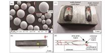
Changjun Han, Daolin Yuan, Zhi Dong, Jinmiao Huang, Chaochao Wu, Jiazhu Wu, Yongqiang Yang, and Di Wang
(2) The stability of the printing process is affected significantly by the process parameters owing to the low melting and boiling points of Zn. Therefore, LPBF machines equipped with the appropriate gas flow field can prevent Zn vapor from destroying laser propagation.(3) When a laser source with Gaussian-distribution characteristics is used, the temperature in the central region of the molten pool exceeds the boiling point, even when a laser power as low as 30 W is used, which is not conducive to the stable formation of Zn. Laser-beam shaping or positive defocusing can be considered to weaken the high energy density in the central region of the laser to reduce evaporation, thus ultimately improving the forming quality of LPBF-printed Zn.ObjectiveLaser powder bed fusion (LPBF) additive manufacturing technology has been widely utilized to fabricate degradable zinc (Zn) implants and is a novel approach for creating complex structures with controllable shape and exceptional performance. However, printing Zn is challenging owing to its evaporative nature and narrow fabricating window arising from its low melting and boiling points. Therefore, a comprehensive investigation must be conducted to reveal the mechanisms of heat and mass transfer in molten pool during LPBF, which can provide theoretical guidance for the optimization of printing-process parameters.MethodsA mesoscopic-scale heat transfer and flow coupling model of molten pool during the LPBF of pure Zn was established using discrete-element and computational fluid dynamics methods. Single molten-track experiments were designed to verify the numerical model. The mechanisms by which the process parameters affect the temperature field, flow field evolution, and morphology of the molten track were discussed.Results and DiscussionsPure Zn is sensitive to changes in transient heat input owing to its low melting and boiling points. Increasing the laser power significantly alters the molten-track size, peak temperature, and cooling rate. Specifically, when the laser power is increased from 30 W to 60 W and 90 W, the real-time volume of the molten pool increases nonlinearly by 510% and 1730%, respectively (Fig. 9). At higher scanning rates, more laser energy is absorbed by the surface of Zn powder, the length-width ratio of the molten pool changes gradually from 1.28 to 1.98, and the length-depth ratio changes from 1.61 to 3.45 (Figs. 4 and 5). Consequently, the molten pool is longer, shallower, and more narrow, thus resulting in larger temperature gradients along the direction of the molten-pool depth, with the maximum cooling rate increasing from 3.6×10⁶ K·s-1 to 1.3×10⁷ K·s-1 (Figs. 6 and 7). Furthermore, the real-time volume fluctuated considerably and erratically during molten-track formation. As the laser energy density within the molten pool increases further, the internal flow accelerates and the evaporation of Zn at the center becomes evident, thus changing the Marangoni convection caused by temperature gradient into evaporative recoil pressure as the dominant driving force for flow within the molten pool. The morphology of the printed molten tracks transformed from central point-like pits into continuous slit-like shapes (Fig. 11). The findings of this study can provide theoretical guidance for the evolution of the molten pool and for optimizing the LPBF processing of metals with low melting and boiling points.Conclusions(1) Significant evaporation is observed under high laser power during the LPBF printing of pure Zn, whereas the molten tracks indicate low stability at high scanning rates. Under laser power levels and laser scanning rates of 45?60 W and 300?600 mm·s-1, respectively, the simulation results indicate strong metallurgical bonding between Zn powders and Zn substrate, thus implying the high stability of the molten tracks.
Oct. 13, 2024Vol. 51 Issue 20 2002301 (2024)
Yan Zeng, Jingyi Guo, Zheming Fan, Kaichi Xu, and Lei Li
The single-channel single-layer and single-channel five-layer depositions are carried out to study the dendritic morphology, crystal orientation, and microstructure. Table 2 lists the DED processing parameters. The evolution of the molten pool geometry and dendritic morphology are observed using a metallographic optical microscope (OM). In addition, the γ/γ′ eutectic band is found using a scanning electron microscope (SEM). The orientations of the epitaxial growth dendritic and stray grains are characterized using an electron backscattered diffraction (EBSD) system with an acceleration voltage of 20 kV, tilt angle of the tested specimen of 70°, and scan step size of 0.5 μm. The ATEX software package is used to conduct the analysis. In addition, the texture and grain misorientation are obtained using the EBSD system to explain the distribution rules of the dendritic morphology and disorientations. The Vickers hardness of the materials in the deposition region is measured using a Vickers microhardness tester with a test pressure of 3 N. To reveal the evolution mechanism of the molten pool geometry, the formation process of stray grains, complex thermal behaviors, and rapid solidification in multilayer DED are investigated by building a 3D transient heat transfer numerical model and solving the conservation equations.ObjectiveNi-based single-crystal turbine blades of aeroengines are inevitably damaged during use. Therefore, it is of great significance for commercial aeroengines with high economic requirements to repair single-crystal turbine blades reasonably and continue to realize their value. Directed energy deposition (DED) is a type of metal additive manufacturing technology that uses a laser as the heat source to repair complex structures with fine metal powders, layer-by-layer. In addition, the high temperature gradient and cooling rate of DED are conducive to the epitaxial growth of Ni-based single crystals. However, owing to complex thermal cycles and molten pool convection, stray grains are the most common defects in Ni-based single crystals repaired by DED. Therefore, to reveal the formation mechanism and provide a reference for the inhibition of stray grains, single-channel single-layer and single-channel five-layers are fabricated via DED, and a macroscopic numerical simulation of the single-channel five-layer deposition is carried out. First, the dendrite morphology, crystal orientation, and microstructure are analyzed. Then, the correlation between the columnar-to-equiaxed transition and stray grain formation is studied, and the microscopic mechanism of stray grain formation is revealed, which contributes to the suppression of stray grains in the middle and bottom of the deposition region and promotes the application of DED technology in the repair of commercial aeroengine single-crystal turbine blades.MethodsThe substrate is a Ni-based single-crystal superalloy, namely, DD6, that has dimensions of 5 mm × 5 mm × 15 mm. The powder is produced via the vacuum induction-melting gas atomization process based on the DD6 alloy, and the diameter of the powder is 53?150 μm. In addition, the substrate surface is polished using alcohol, and the powder is dried in a vacuum oven for 150 min at (120 ± 5)℃ before use.Results and DiscussionsAccording to the dendrite morphology, under the current deposition process parameters, single-channel single-layer DD6 alloy deposition can realize the epitaxial growth of columnar crystals, except for the top stray grain, and there are no obvious porosities, inclusions, or other defects (Fig. 2). Compared with single-channel single-layer deposition, the thermal cycles and cooling conditions during single-channel five-layer deposition are more complicated, which results in a columnar-to-equiaxed transition (CET) in not only the top region but also the middle region (Fig. 3). Simultaneously, the predeposited layer experiences a similar short-term solid solution in the subsequent deposition process, which affects the formation and evolution of the precipitated phase. In addition, the epitaxial growth of the interlayer columnar crystals is difficult to control, and stray grains are inevitable in the deposition area (Fig. 4). The Vickers hardness decreases with an increasing deposition height; however, the stray grains at the fusion line and top of the deposition region significantly decrease the Vickers hardness (Fig. 5). The change in the solidification parameters and molten pool convection during the DED of the DD6 single-crystal alloy result in differences in the element concentration and precipitation time between the dendrite core and interdendrite (Fig. 10). In this case, the directional coarsening of the γ' phase results in the formation of γ/γ' eutectic bands in the region where CET occurs. These eutectic bands appear at the boundaries between the columnar and equiaxed grains, which are shown as grain boundaries between the columnar and stray grains at the mesoscale (Fig. 11).ConclusionsThe single-layer deposition of the DD6 single-crystal alloy can realize the epitaxial growth of columnar crystals, except for the top stray grain. The stray grains in the five-layers are primarily caused by the collapse of the fusion line and CET in the top region, and the presence of stray grain crystals significantly reduces the Vickers hardness of the material. There is a difference in element concentration in the CET region, and similar solid solution treatments under subsequent temperature cycling lead to the directional coarsening of the γ' phase and then produce γ/γ' eutectic bands. The γ/γ' eutectic bands exist in not only the top deposition region but also the middle deposition region. The γ/γ' eutectic bands exist at the boundary between columnar and equiaxed grains, and they penetrate the dendrite core and interdendrite.
Oct. 25, 2024Vol. 51 Issue 20 2002302 (2024)
Liangliang Zhang, Minjie Wang, Hongxia Li, Jianye Liu, Jinhai Wang, and Liuhui Niu
ObjectiveBased on the forming principle of rapid melting and layered printing using selective laser melting (SLM), there are more or fewer pores in the interior of fabricated metal parts, which directly affects the mechanical properties and service performance of the metal parts. In many studies, emphasis has been placed on reducing pore defects and increasing the density of printed metal parts. However, the presence of internal pores in printed metal materials is not entirely unfavorable. By changing the 3D printing process conditions to make the internal pores connected and controllable, the porosity can be greatly improved, and the pore structure characteristics can be customized according to requirements, which provides a new idea for the research of permeable metal materials. The application of 3D printing for the preparation of permeable steel takes advantage of this unique property. However, research on the 3D printing of permeable steel using the SLM process is still in the initial stage, and there are few literature reports on the formation connectivity mechanism of the pore structure and permeability performance. In this study, we combine a theoretical analysis with experiments to study the permeability mechanism of printed permeable steel. A theoretical model of permeability is established, and the influence of the printing parameters on the pore characteristics and permeability of the permeable steel is studied. We hope that this innovative method of preparing microporous interconnects via SLM can contribute to the additive manufacturing of permeable steel.MethodsFirst, based on the melting accumulation forming method of the 3D printing process, the arrangement of the scanning melt channels is controlled to regularly create pores. The formation connectivity mechanism of pores in printed permeable steel is revealed by constructing a pore structure model. Subsequently, the relationship between the printing process parameters and permeability coefficient is established to perform a theoretical analysis of the permeability mechanism of permeable steel. In addition, permeable steel with micrometer pores is prepared via the SLM process. Combined with a gas penetration test and microstructural observations, the influence of the printing process parameters on the pore characteristics and permeability of the designed and prepared permeable steels is discussed in detail. Moreover, the relationship between the calculated and experimental results of the permeability coefficient is analyzed to verify the validity of the model for predicting the permeability coefficient.Results and DiscussionsIn the cross-sectional view of the permeable steel prepared with a small hatch distance, the formed pores are unevenly distributed and irregularly shaped, and there are obvious pore plugging phenomena (Fig. 6). The side view shows that the longitudinal overlap characteristics of the melt channel are irregular and that the formation of twisted and discontinuous channels leads to poor pore connectivity (Fig. 7). With increasing hatch distance, the pore morphology significantly improves, and the pore structure with an obvious grid distribution has good preparability and regularity. In addition, the longitudinal arrangement of the melt channel is uniform, and the size of the strip-shaped pore channels gradually increases, which is conducive to improving the pore connectivity and permeability. Furthermore, the porosity and pore size of the permeable steel exhibit clear upward trends with increasing hatch distance (Fig. 9). Moreover, the change in the permeability of the permeable steel is proportional to the overall porosity. The increase in porosity and pore size is conducive to the improvement in gas flow, and the permeability coefficient significantly increases, indicating that the printed permeable steel has good permeability (Fig. 11). Furthermore, the calculation results of the permeability coefficient are similar to the experimental results, and they have suitable consistency, which verifies the effectiveness of the model for predicting the permeability coefficient of printed permeable steel (Fig. 12).ConclusionsIn the present study, permeable steel with micrometer pores is printed using the SLM process. The formation connectivity mechanism of the pore structure is studied, and the relationship between the printing process parameters and the permeability coefficient is established to perform a theoretical analysis of the permeability mechanism. In addition, the porosity and pore size of the permeable steel can be effectively adjusted by controlling the hatch distance, which is conducive to forming a regular pore structure with a grid distribution, and the porosity and pore size are 5.91%?19.97% and 39.18?138.67 μm, respectively. Based on the gas permeation test, the permeable steel has good permeability. The permeability coefficient shows an obvious upward trend with increasing hatch distance, and the test results are 2.48×10⁻¹²?4.05×10⁻¹² m2. The improvement in permeability is closely related to the increase in porosity and pore size, indicating that the pore structure formed in the building direction has suitable connectivity, which provides a strong foundation for gas penetration. Therefore, the permeability of permeable steel can be adjusted to a certain extent by controlling the hatch distance. Moreover, the effectiveness of the theoretical model for predicting the permeability coefficient is verified by analyzing the relationship between the calculated and experimental results.
Oct. 12, 2024Vol. 51 Issue 20 2002303 (2024)
Ning Wang, Zhenhua Li, Bibo Yao, and Baoren Teng
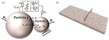
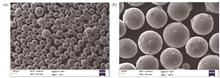
ObjectiveSpherical powders with particle sizes of 15?53 μm are usually employed in selective laser melting (SLM) process. The difficulty in producing SLMed parts results in high costs. Large particle size powders with particle sizes of over 100 μm are comparatively easier to produce and inexpensive. Hence, the application of large-size powders in the SLM process reduces the cost of the SLMed parts because high-power lasers are available. Additionally, the use of large-size powders for high layer-thickness SLM can significantly reduce the manufacturing costs and enhance efficiency. However, the process is challenging, owing to the potential defects associated with the SLM of high layer-thickness large-size powders, which ultimately results in lower density and inferior mechanical properties. Research on the large-size powder SLM is still in its early stages, and the process parameters are not optimized. In this study, large-size Ti6Al4V powder with a particle size of 100?200 μm is used in a SLM process to fabricate samples with a layer thickness of 120 μm. The effects of the laser power, scanning speed, and hatch spacing on the SLM process, defects, microstructures, and properties of the fabricated samples are investigated based on the results of numerical simulations and experiments. The process parameters are optimized, and high-density samples are further analyzed to explore their microstructure and mechanical properties. Hence, this study provides guidance for the application of large-size Ti6Al4V powder in the SLM process.MethodsThe ANSYS software is used to simulate and track the temperature field of a single layer and calculate the size of the molten pool. Ti6Al4V powder with a particle size of 100?200 μm, produced via the gas atomization method, is employed to fabricate the SLMed parts. The process parameters are: a layer thickness of 120 μm, laser power of 340 W to 370 W, and scanning speed of 800 mm/s to 1100 mm/s. Samples and tensile blocks are fabricated via laser scanning with an interlayer rotation of 67°, and the parameters are optimized based on the results of the numerical simulations and single-pass experiments. After wire-cutting the substrate, the samples and blocks are cleaned, the relative density is measured via the Archimedean method, and the samples are polished for metallographic observation. The hardness of the samples is measured using an automatic micro-Vickers hardness tester, mechanical properties are tested using a tensile testing system and tensile fractures are characterized by a scanning electron microscope.Results and DiscussionsThe width and depth of the molten pool scanned by a 370 W laser exceed 200 μm at all scanning speeds, which makes obtaining dense samples possible. The calculated results of the established finite element model are in good agreement with the experimental results, with a difference of less than 6%, which confirms the reliability of the model. The hatch spacing has a significant effect on the defects in the fabricated samples. It is difficult to obtain a high-density sample when the hatch spacing is greater than 0.14 mm (Fig. 10). The largest-size samples with a relative density of 99.64% (Fig. 10), are achieved at a laser power of 370 W, scanning speed of 1050 mm/s, and hatch spacing of 0.10 mm without noticeable defects, such as porosity and cracks (Fig. 13). The tensile and yield strengths (σ0.2) of the optimized samples are 1197 MPa and 1112 MPa, respectively, and the elongation is 8.2% (Fig. 14). The tensile samples show mixed tough-brittle fracture characteristics with disintegration features and several tough dimples with 2?5 μm size (Fig. 15). The mechanical properties of the SLMed samples with large-size powders under high layer- thickness are comparable to those of the SLMed samples with small-size powders under low layer-thickness, whereas the building rate is 3?5 times that of the conventional process (Fig. 16). The processing cost significantly reduces because of the low price of the large-size Ti6Al4V powder and high building rate.ConclusionsThe SLM process is optimized for obtaining large-size Ti6Al4V powder with a particle diameter of 100?200 μm. The relative density of the fabricated samples reaches 99.64% at a layer thickness of 120 μm, laser power of 370 W, hatch spacing of 0.1 mm, and scanning speed of 1050 mm/s. The tensile strength, yield strength, and elongation of the sample prepared under the optimized process are 1197 MPa, 1112 MPa, and 8.2%, respectively, which are comparable to the performance of the samples fabricated using small size powders under low layer-thickness. The building rate of the sample is 12.6 mm3/s, which is 3?5 times that with the small-size powders under lower layer-thickness.
Oct. 12, 2024Vol. 51 Issue 20 2002304 (2024)
Zhixu Xu, Yanhua Zhao, Weifang Xie, Xiuping Han, Yanle Li, Hua Tian, Lei Chen, and Bin Tan
ObjectiveLaser directed energy deposition (L-DED) uses a laser as the energy source, which has higher temperature gradient and cooling rate, making it easier to alleviate metallurgical defects and promote the directional growth of crystals. However, during the preparation of multi-layer single crystal alloys, the heat input inside the molten pool is constantly changing, which increases the complexities of heat transfer and solidification in the molten pool. This is not conducive to the directional growth of crystals, and increases the risk of formations of stray grains and cracks. Therefore, this study reports the effects of the laser power, powder feeding rate, and scanning speed on the microstructure and defects of single-channel single-layer samples. The effects of single-channel multi-layer and multi-channel multi-layer deposition strategies on the crystal growth and micro-defects are also presented. The results of this study can be used as a reference for the L-DED forming of single crystal components.MethodsFirst, single-channel single-layer DD6 nickel-based single crystal superalloy samples are prepared using L-DED at different laser power values, and the microstructures of the samples are studied using optical microscope (OM). Then, samples are prepared using different laser power values, powder feeding rates, and scanning speeds in an orthogonal experiment. The microstructure of each sample is observed using OM, and the directional growth height of the crystals (HE), molten pool depth (HR), deposition height (HD), and crystal directional growth ratio HE/(HR+HD) are measured. A range analysis is also performed. Then, the microstructures of single-channel multi-layer and multi-channel multi-layer samples prepared using a continuous deposition strategy are examined using OM and scanning electron microscope (SEM), and the precipitates are identified using energy dispersive spectrometer (EDS). Finally, the microstructures and grain orientations of single-channel multi-layer and multi-channel multi-layer samples prepared using an intermittent deposition strategy are characterized using OM, SEM, and electron back scatter diffraction (EBSD).Results and DiscussionsWhen the laser power is too low, the heat input is insufficient, and defects such as lack-of-fusion holes, pores, and cracks are observed inside the sample. As the laser power gradually increases, the intensity of the Marangoni convection inside the molten pool increases. This results in a wavy molten pool morphology and increased tendency to generate stray grains. When the laser power is too high, the heat accumulation further increases, and cracks form under the combined actions of the thermal stress and liquid film (Fig. 2). The samples formed under different laser power values, powder feeding rates, and scanning speeds have large areas of stray grains on both sides of the molten pool, and the growth of columnar crystals in the middle area is relatively good. When the heat input per unit time is too large, the directional growth of crystals is poor, and the deposition height is insufficient. The internal stress of a sample also increases, thereby increasing the tendency to produce cracks (Figs. 3?5). The HE, HD, and HE/(HR+HD) values of the samples produced under different process parameters are listed in Table 4, with the results of range analyses listed in Tables 5?7. The optimal process parameters are a laser power of 1000 W, a scanning speed of 15 mm/s, and a powder feeding rate of 10 g/min. Under these process parameters, HE/(HR+HD) is 73.02%, HE is 474.55 μm , and HD is 257.30 μm . The crystal shows good directional growth and no defects such as cracks and pores. The HE/(HR+HD) value for single-channel 30-layer samples reaches 83.05% when using the continuous deposition strategy. The primary dendrite arm spacing at the bottom of the molten pool is approximately 3.8 μm . When the deposition height is gradually increased, the heat accumulation increases, which decreases the temperature gradient in the molten pool and increases the dendrite arm spacing of the high deposition layer to 19.5 μm . The direction of heat dissipation is also easy to change, resulting in the formation of a secondary dendrite arm with an arm spacing of 2.2 μm (Fig. 6). In the multi-channel 10-layer sample produced using the continuous deposition strategy, the bottom of the molten pool has a wavy morphology, and the HE/(HR+HD) value is only 69.53% (Fig. 7), with Re segregated inside the columnar crystal and Ta segregated between the columnar crystals (Fig. 8). When single-channel multi-layer samples and multi-channel multi-layer samples with a height of approximately 4.6 mm are deposited using the intermittent deposition strategy, which reduces the heat input per unit time, improves the morphology of the molten pool, and alleviates the generation of deflecting dendrites, the HE/(HR+HD) values are 83.73% and 88.63%, respectively. However, there is still a small amount of deflecting dendrites in the single-channel multi-layer samples produced using the continuous deposition strategy, is along with an overlap rate in the multi-layer samples, which can remelt the wavy molten pool and primary deflecting dendrites, thereby reducing the internal deflecting dendrites (Figs. 9 and 10). The crystal orientation differences at the bottoms of the single-channel multi-layer and multi-channel multi-layer deposition areas of samples produced using the intermittent deposition strategy are basically within 10°, and an overall single-crystal structure is produced (Fig. 11).ConclusionsThis study reports the effects of different L-DED molding process parameters and deposition strategies on the micro-defects and directional crystal growth of samples. When the laser power is too low, it is easy to produce a large number of lack-of-fusion holes and pores. When the laser power is too high, the tendency to form stray grains and cracks increases. When using a laser power of 1000 W, a scanning speed of 15 mm/s, and a powder feeding rate of 10 g/min, taking into account the forming quality and deposition efficiency, the HE/(HR+HD), HE, and HD values are 73.02%, 474.55 μm, and 257.30 μm, respectively.
Oct. 12, 2024Vol. 51 Issue 20 2002305 (2024)
Xin He, Xia Luo, Jingang Tang, Zhuang Zhao, Yuhong Dai, and Bensheng Huang
ObjectiveSelective laser melting (SLM) can be used to prepare functionally gradient materials (FGMs) for local customization of performance. In this study, CuSn10/AlSi10Mg functional gradient materials were prepared by SLM, and the effect of the material composition ratio on the microstructure of the CuSn10/AlSi10Mg transition layer was investigated. The phase and quantity of the transition layer were calculated using CALPHAD, the microstructural evolution of the interface region of the gradient materials was discussed based on electron backscattering diffraction (EBSD) results, and the formation mechanism of cracks in the interface region was revealed. The results show that the microstructure of the CuSn10/AlSi10Mg transition layer consists of a matrix of Al4Cu9 and Al2Cu with columnar and fine equiaxed grains. In the transition layer zone (from the copper alloy side to the aluminum alloy side), with an increase in the AlSi10Mg content, the matrix content does not change significantly, whereas the content of Al/Cu intermetallic compounds changes sharply. The Al4Cu9 phase first precipitates and its content gradually decreases, whereas the Al2Cu phase precipitates later and its content gradually increases, and a large amount of Al/Cu intermetallic compounds are generated around the cracks. The main reason for the formation of severe cracks in the transition zone is that the directly generated Al4Cu9 phase is prone to large volume changes (4.4%), leading to stress concentration and initial microcracks. The large volume change (4.3%) caused by the transformation of the Al2Cu phase and Cu enriched in the matrix into the Al4Cu9 phase (indirectly generated) further exacerbates the stress concentration and ultimately leads to macrocracking. Avoiding the direct and indirect generation of Al4Cu9 is the primary means of solving the problem of cracking. The microhardness of the transition layer is higher than that of the matrix on both sides. The highest hardness is observed at the crack (804 HV), similar to that of Al4Cu9.MethodsIn this study, CuSn10/AlSi10Mg gradient functional materials are prepared by SLM through two gradient paths (19 and 16 layers of different compositional gradients are designed for samples 1 and 2, respectively). The microstructures of the different transition regions are observed by optical microscopy (OM) and scanning electron microscopy (SEM) equipped with energy dispersive spectroscopy (EDS). To reveal the microstructural evolution, the phase compositions of the transition regions are measured using X-ray diffraction (XRD) and EBSD. Finally, the microhardness is measured using a microhardness tester to understand the changes in mechanical properties.Results and DiscussionsSample 1 (19-layer transition composition) prepared using SLM forms more cracks, generates transverse cracks, and causes macroscopic cracking throughout the sample. Sample 2 (16-layer transition composition) forms slight cracks, and the transverse cracks disappears. Although both transition compositions have cracks, the 19-layer transition is significantly more severe than the 16-layer transition. More importantly, nearly all the cracks are generated in the Al-rich transition region (Fig. 2). During the printing process, the distribution of Al along the deposition direction gradually increases from zero at the beginning to a uniform distribution at the end, which is consistent with the spot scanning results. However, both Cu and Sn are uniformly distributed throughout the transition region, which further confirms that the CuSn10 alloy is continuously remelted and is then diffused to the upper layer during the printing process, resulting in the enrichment of Cu in the region of the Al alloy (Fig. 4). In the transition region, the phases mainly consist of the matrix phase α-Cu/α-Al and Al/Cu intermetallic compounds, and the intermetallic compounds are mainly Al4Cu9 and Al2Cu. From the Cu alloy side to the Al alloy side, the content of the matrix does not change significantly with the addition of the Al alloy. In addition, Al4Cu9 first precipitates and then gradually decreases, and it is dominant at 40% AlSi10Mg. With a continuous increase in the Al alloy content, the Al2Cu phase precipitates later and gradually increases, exceeding the Al4Cu9 phase at 50% AlSi10Mg content (Figs. 5?7).ConclusionsThe microstructure of the SLMed CuSn10/AlSi10Mg gradient material is composed of columnar and fine equiaxed grains that grow in the direction of the center of the molten pool, and the equiaxed grains close to the boundary of the molten pool have a random grain orientation. In the transition region, the phases mainly consist of α?Cu/α?Al matrix and Al/Cu intermetallic compounds, and the intermetallic compounds are mainly Al4Cu9 and Al2Cu. From the Cu10Sn side to the AlSi10Mg side, with the addition of the Al alloy, the content of the matrix does not change significantly, but Al4Cu9 first precipitates and gradually decreases, and it dominates at 40% AlSi10Mg. With a continuous increase in the aluminum alloy, the Al2Cu phase precipitates later and gradually increases, exceeding the content of the Al4Cu9 phase at 50% AlSi10Mg. A large amount of the Al4Cu9 phase is generated around the microcracks in the transition region. However, a large amount of the Al2Cu phase is generated around the macrocracks, and nearly all cracks mainly occur in the Al-rich transition region. The volume change of the generated Al4Cu9 is the highest (4.4%), and the reaction between Al2Cu and the Cu matrix forming the Al4Cu9 phase exhibits the second-highest volume change (4.3%), whereas the volume change forming the Al2Cu phase is only 0.3%. The Al4Cu9 phase nucleates in both Al- and Cu-rich solid solutions, whereas the Al2Cu phase can only nucleate in the Al-rich region. Therefore, the reason for crack formation is that the direct generation of the Al4Cu9 phase in the transition region is prone to forming a stress concentration that generates the initial microcracking. The indirectly formed Al4Cu9 (the reaction between Al2Cu and excess Cu in the matrix) causes a large volume change and further aggravates the stress concentration, resulting in severe macrocracks. Avoiding the generation of the Al4Cu9 phase (including direct and indirect formations) is the primary means of solving the cracking problems. The microhardness of the transition layer region is affected by the intermetallic compound content. From the Cu alloy side to the Al alloy side, the microhardness first increases and then decreases, and it is higher in the transition region than that of the substrate. This trend is consistent with the number of intermetallic compounds. The highest microhardness (804 HV) is observed at the cracks, which is very close to that of Al4Cu9. This further verifies that enriched intermetallic compounds are the main reason for crack formation.
Oct. 14, 2024Vol. 51 Issue 20 2002306 (2024)
Yali Li, Yanli He, Jun Fu, and Jianfeng Zhang
ObjectiveHastelloy X alloy is commonly used to manufacture high-temperature components such as the combustion chambers of aero-engines by selective laser melting (SLM). In practice, even when using the same SLM process, heat treatment, and hot isostatic pressing process, there are differences in the microstructures and mechanical properties of different batches of Hastelloy X alloy parts. There is a strong correlation among these differences and differences in the compositions of the batches of Hastelloy X alloy powder raw material used. In particular, the influence of the Si element is the most significant. The existing research mainly focuses on the use of the Si element in the traditional casting or forging process for the preparation of nickel-based high temperature alloys, with little attention given to the Si element in the Hastelloy X alloy in SLM-related research. This study discusses the effect of Si on the microstructure and stress rupture properties of SLM formed Hastelloy X alloy parts, with a view to providing useful guidance for optimizing their quality.MethodsTwo batches of gas-aerosolized Hastelloy X powders with different Si compositions, A ( Si mass fraction of 0.071%) and B (Si mass fraction of 0.365%), are used in this experiment, with particle sizes ranging from 15 μm to 45 μm. The experiment is carried out using the SLM equipment. The SLM forming parameters of the two batches are the same, and the specimens are placed in the length direction parallel to the substrate (transverse specimens). After the SLM is finished, each sample is subjected to hot treatment at 1050 ℃ for 1 h to remove the thermal stress, and then hot isostatic pressing at 1150 ℃ for 2 h is performed. A scanning electron microscope (SEM) is used to observe the high magnification microstructure of the Hastelloy X alloy, and the compositions of the phases at the grain boundaries are analyzed using an SEM energy dispersive spectrometer (SEM-EDS). The type of needle-like precipitates is analyzed using a transmission electron microscope (TEM). The stress rupture properties are tested using an electronic creep and stress-rupture testing machine at 815 ℃ and 105 MPa. Finally, the stress rupture fracture is observed using an SEM.Results and DiscussionsBefore the stress rupture test, the specimens in batch A contain precipitated Cr-rich and Mo-containing M23C6-type carbides with a chain-like distribution at the grain boundaries [Fig. 2(a)], while the specimens in batch B contain precipitated Mo-rich M6C-type carbides distributed in a more continuous manner at the grain boundaries [Fig. 2(c)]. After the stress rupture test, there is no obvious change in the type of grain boundary precipitates (Fig. 3), but there are a large number of needle-like precipitates present in the grains of the specimens in batch B, with compositions that include Mo, Si, and W (Fig. 4). Diffraction patterns show that the precipitation phase has a tetragonal structure (Fig. 5), with the lattice constants of a=3.2, b=3.2, and c= 7.8, and atomic mass ratio of Mo, Si, and W is 1∶2.4∶0.3. The carbide morphology at the grain boundaries of the specimens in batch B promotes crack initiation and extension, affects the bonding force between grain boundaries, and leads to grain boundary embrittlement. A large number of needle-like MoSiW hard and brittle phases are precipitated within the grains during the stress rupture test, which reduces the stress rupture properties of the alloy.ConclusionsBefore the stress rupture test at 815 ℃ and 105 MPa, the carbides of the specimens in batch A are precipitated at both grain boundaries and inside the grains. The grain boundary precipitates have a chain-like distribution, and the carbide type is Cr-rich M23C6. In contrast, the carbides of the specimens in batch B are precipitated almost exclusively at the grain boundaries in a continuous pattern, and the carbide type is Mo-rich M6C. After the durability test, no significant change is seen in the precipitates of the specimens in batch A, but the specimens in batch B show a needle-like precipitation phase (MoSiW) inside the grains. In addition, the durability properties of the specimens in batch A reach the standard of Hastelloy X alloy forgings, while the stress rupture properties of the specimens in batch B show low plasticity, and the average elongation is 6.4%, which is lower than that of the standard of Hastelloy X alloy forgings. The shape, distribution, and type of the Hastelloy X precipitation phases are closely related to the Si content. A high Si element content (mass fraction of 0.365%) leads to the significant precipitation of a hard brittle needle-like phase within the grains and continuous carbon outgrowth at the grain boundaries during the stress rupture test, which affects the bonding force between the grain boundaries and reduces the stress rupture properties of the alloy.
Oct. 12, 2024Vol. 51 Issue 20 2002307 (2024)
Yihui Zhang, Tongbo Wei, Chenyu Su, Jingjing Yang, and Zemin Wang
ObjectiveMnCu alloys, a shape memory alloy (SMA) type, exhibit good mechanical bearing performance, shape memory effect, damping performance, and low manufacturing cost. Furthermore, the alloys are easy to process. Therefore, MnCu-based SMA can potentially replace NiTi-based alloys in specific applications. Moreover, the alloy has application prospects in vibration reduction in aerospace, ships, vehicles, and machinery manufacturing. High manganese-type MnCu alloy (atomic fraction of Mn>70%) with high functional properties exhibits poor elongation. It is also readily brittle and oxidizes during high-temperature manufacturing. In the conventional manufacturing methods for MnCu alloys, complex structures such as lattice, inner channels, truss, and thin walls cannot be effectively completed. Hence, we select selective laser melting (SLM) to process MnCu alloy. SLM is a typical metal additive manufacturing technology. Different SLM manufacturing parameters and heat treatment methods significantly influence the properties of MnCu alloy samples. Therefore, in this study, we first study the influence of varying scanning speeds on the relative density of Mn-30%Cn alloy samples made from SLM to find a process window suitable for processing MnCu alloys. Second, we study the effects of SLM process parameters and cyclic heat treatment on the grain size, phase composition, phase structure, chemical composition, and microhardness of MnCu alloys. Finally, we obtain the comprehensive effects of SLM process parameters and cyclic heat treatment on the sample.MethodsIn this study, a planetary ball mill employs Al2O3 as a grinding medium to mix the Mn and Cu powders with 70:30 mass ratio. Then, we prepare cubic samples based on the mixed powders using the self-developed SLM instrument at different scanning speeds. Furthermore, we divide the Mn-30%Cu alloy prepared using SLM into two groups; one has cyclic heat treatment, and the other does not. The scanning tracks and grains on the surface of the sample are observed using an optical and electron microscope at different magnifications. Subsequently, the scanning track width and grain size are measured and compared. An X-ray fluorescence spectrometer is used to analyze and compare the phase composition of the samples before and after heat treatment. Moreover, the micro Vickers hardness tester is used to calculate the microhardness of the sample surface. Grain orientation difference is measured using electron backscattering diffraction.Results and DiscussionsThis study innovatively investigates the effect of cyclic heat treatment on Mn-30%Cu alloy samples. Compared with conventional heat treatment, abnormal grain growth is observed in the samples with epitaxial mixed grains with two types of grain sizes (2‒5 μm and 140‒240 μm) in the samples after cyclic heat treatment . The coarse grain size is approximately two orders larger than the fine grain size. In addition, a significant gap in hardness between coarser and finer grains in Mn-30%Cu alloy is observed. Furthermore, the microhardness of the finer grains is in the range of 145‒156 HV, which is close to the hardness of the alloy without heat treatment. In contrast, the microhardness of large grains is 130‒135 HV, which is significantly lower than that of small grains. Therefore, it ultimately decreases the microhardness of the Mn-30%Cu alloy samples after heat treatment.ConclusionsWhen the laser power is 196 W, hatching distance is 0.06 mm, layer thickness is 0.02 mm, and scanning speed is 500‒600 mm/s, the relative density of Mn-30%Cu alloy reaches its highest (>99.7%). The pores form when the scanning speed is lower than 500 mm/s; incomplete fusion forms when the scanning speed is higher than 600 mm/s. The Mn-30%Cu alloy formed by SLM mainly comprises γ-(Mn, Cu) phase grains with grain sizes of 0.5‒1.6 μm. As the scanning speed increases from 300 mm/s to 700 mm/s, the grain size decreases first and then increases. During cyclic heat treatment, the Mn-30%Cu alloy expands abnormally, resulting in equiaxed mixed grains with 2‒5 μm and 140‒240 μm sizes. In addition, a small amount of γ- (Mn, Cu) undergoes martensitic transformation to produce γ´-(Mn, Cu) or precipitate a small amount of α-Mn phase. The Mn-30%Cu alloy will exhibit Mn burning phenomenon during SLM. The burning ratio of Mn element decreases from 16.4% to 3.9% with the increase of scanning speed (i.e., the decrease of laser energy density). The microhardness of SLM-formed Mn-30%Cu alloy is mainly influenced by the relative density, chemical composition, phase composition, and grain size. After heat treatment, the microhardness of Mn-30%Cu alloy decreases from 143‒153 HV to 137‒145 HV.
Oct. 25, 2024Vol. 51 Issue 20 2002308 (2024)
Siyu Zhou, Mingchen Fang, Guang Yang, Zhonggang Sun, Siyuan Zhang, and Changfu Li
After introducing the slow-heating treatment, the mass fraction of primary α phase decreases from 58% in the as-deposited state to 34%. The plate-like primary α phase transforms into short rod-like primary α phase. The aspect ratio decreases from 8.85 to 3.75. The continuous grain boundary α phase fractures, and the linear undissolved regions disappear.After the slow-heating treatment, owing to the transformation of the plate-like primary α phase into short rod-like primary α phase and the fracture of the continuous grain boundary α phase, the tensile strength of Ti-5Al-4Mo-3V-2Zr-Nb becomes 1015 MPa, which is 5.8% lower compared to that of the as-deposited state. The elongation after fracture is 15.6%, which is 59% higher compared to that of the as-deposited state.ObjectiveTi-5Al-4Mo-3V-2Zr-Nb (hereinafter referred to as Ti-5321G) is a metastable β alloy with high specific strength and excellent corrosion resistance and has a wide range of applications in the aerospace field. Laser deposition manufacturing (LDM) is a layer-by-layer manufacturing method with high material utilization, high freedom of forming and almost unlimited material types. However, Ti-5321G samples formed through LDM generally have continuous linear grain boundaries of α phase, resulting in poor strength-ductility match. Thus, the application of Ti-5321G is extremely limited. Therefore, it is necessary to perform specific heat treatment on Ti-5321G formed through LDM to disrupt the continuous linear grain boundaries of α phase and improve its strength-ductility match. Ultra-slow heating treatment(SHT) is employed to break the continuous linear grain boundaries of α phase and enhance material strength-ductility match. The influence of slow heating treatment on the microstructure and properties of Ti-5321G is investigated.MethodsFirst, Ti-5321G samples are formed through LDM. Second, the as-deposited Ti-5321G samples are annealed at 870 ℃ for 0.5 h and then water-quenched. Subsequently, the samples are heated to 810 ℃ at a heating rate of 1.24 ℃/min and held for 2 h. The samples are then furnace-cooled to 730 ℃, held for 2 h, and air-cooled, followed by 580 ℃/4 h aging treatment. Third, the microstructure of Ti-5321G samples formed by LDM after ultra-slow heating treatment is observed using optical microscope (OM) and scanning electron microscope (SEM). The content and size of α phase are measured using Image pro plus 6.0. Finally, tensile tests are conducted on the samples, and the fracture morphology is observed using SEM for performance evaluation.Results and DiscussionsThe microstructure of Ti-5Al-4Mo-3V-2Zr-Nb samples formed through LDM is shown in Fig. 3. It is characterized by plate-like primary α phase (αp) and residual β phase, with secondary α phase (αs) distributed in a needle-like manner in the gaps of αp. Linear continuous grain boundary α phase (αGB) can be observed at the grain boundaries. The plate-like αp is distributed in a mesh-like structure in some areas and randomly distributed on the β matrix in other areas. Continuous undissolved regions appear on both sides of the linear αGB. The microstructure of the as-deposited samples after SHT is shown in Fig. 4. After the SHT, the continuous linear grain boundary α phase and the internal structure become more uniform. The plate-like primary α phase is transformed into short rod-like primary α phase under high temperature annealing treatment. Some retained deposition-like mesh-like structures consist mostly of uniformly oriented structures. After SHT, the mass fraction, aspect ratio, and length of the αp are approximately 42%, 3.75, and 0.51μm, respectively. The αs is mainly in the form of short rods, with a small portion appearing as equiaxed. The tensile properties of the as-deposited samples and those after SHT are listed in Table 3. The tensile and yield strengths of the as-deposited samples are 1077.5 MPa and 1600.4 MPa, respectively, with an elongation of 9.8%. After SHT, the tensile strength of the samples is 1015.8 MPa, a decrease of 5.8% compared to that of the as-deposited state. The yield strength and elongation are 990.1 MPa and 15.6%, respectively, which are 7.1% lower and 59% higher than those of the as-deposited state, respectively. After SHT, the α phase is coarsened. Compared with the needle-like α phase in the as-deposited state, the short rod-like α phase after SHT has a weaker resistance to plastic deformation. The short rod-like α phase can be easily slipped by dislocations, and the effect of dislocation strengthening is reduced. However, it has better plastic deformation ability. During plastic deformation, the short rod-like α and β phases experience similar strain; thus, they must be subjected to smaller stress compared to the needle-like α phase to avoid the generation, connection, and propagation of microcracks at the α/β phase boundary. The plasticity of the material is improved. The fracture mode of the LDM-formed specimens is a mixed fracture, whereas that of the specimens after SHT is a ductile fracture.ConclusionsThe microstructure of Ti-5Al-4Mo-3V-2Zr-Nb alloy formed through LDM consists of plate-like αand β phases, and needle-like secondary α phase. Continuous linear grain boundary α phases appear, accompanied by linear undissolved regions. The tensile strength is 1077 MPa and the elongation is 9.8%.
Oct. 12, 2024Vol. 51 Issue 20 2002309 (2024)
Kaifei Zhang, Qi Chen, Ran Yan, Shuai Ma, Zhaowei Xiang, and Bo Yuan
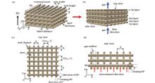
(1) Improving the SIMP method using IAC filters can realize a self-supporting TO design for LPBF, thus enabling the formation of designed components without incorporating additional support; additionally, the IAC significantly affects the optimization space.(2) A comparative analysis of the optimization results of MBB beams and the remaining three validation cases shows no clear pattern between the use of IAC filters and changes in the topology stiffness.(3) Compared with a self-supporting TO algorithm with an equal-value IAC, a variable-value IAC significantly enhances the structural stiffnesses of topological MBB beams, L-beams, compression structures, and cantilever beams, where the stiffness enhancement becomes more evident as the retained volume fraction decreases.ObjectiveAdditive manufacturing (AM) enables the fabrication of extremely complex structures, which can reveal the full potential of topological optimization (TO). However, it presents certain limitations that should be considered in TO. A typical example is that an overhang structure cannot be easily formed in AM without incorporating additional support structures. Therefore, many self-supporting TO algorithms have been proposed to avoid generating components with overhanging structures by considering the incline angle constraint (IAC). The IAC is usually set to a constant value, typically 45°, at all polar angles. Although it can realize the self-supporting design of components and features high versatility, the effects of the AM process and equipment performance on the IAC are typically disregarded, thus resulting in a self-supporting TO algorithm with subpar performance. To fully understand the active role of TO, a self-supporting TO design method that considers the powder-recoating process is proposed based on the characteristics of the laser powder-bed fusion (LPBF) process and equipment.MethodsIn this study, based on the authors' previous study where the changing law of the IAC due to the powder-recoating process in LPBF was investigated, a new self-supporting TO design method is proposed. First, the method for determining the IAC was reviewed; notably, the IAC is not constant but changes with the polar angle. Subsequently, a variable-value IAC was proposed after a mathematical formula for the change in the IAC with the polar angle was derived. Second, a variable-value IAC was integrated into an improved solid isotropic material with penalization (SIMP) TO algorithm in the form of a filter using the min–max operator. Third, the proposed algorithm was validated using two-dimensional (2D) and three-dimensional (3D) MBB beam examples and supplemented with additional examples using an L-beam, a compression structure, and a cantilever beam to generalize the results. Finally, a set of 3D TO MBB beams was selected to be formed via LPBF to further validate the effectiveness of the variable-value IAC.Results and DiscussionsIn this study, we used 2D and 3D MBB beams as examples to investigate the change rule of component performance during component change while maintaining the volume fraction within 0.2?0.7 under the conditions of variable-value IAC, equal-value IAC, and no IAC. The examples show that in the MBB beams, the advantage of having no IAC is the most significant, followed by that of the variable-value IAC. Additionally, the final flexibility curves corresponding to the three TO methods converge gradually as the retained volume fraction increases. In particular, when the retained volume fraction is greater than 0.6, the three curves almost overlapped. An L-beam, a compression structure, and a cantilever beam were added as supplementary calculation examples for validation. The final flexibility value of the L-beam using the variable-value IAC is 2.252×10⁻³, which is lower than those using the equal-value IAC (2.383 × 10⁻³) and without the IAC (2.315×10⁻³), where the stiffnesses increase by 5.5% and 2.72%, respectively. This indicates that the variable-value IAC can better unleash the potential of TO. However, combining the above with the aforementioned MBB beam optimization results, one cannot conclude that the TO structures without the IAC are better than those with the IAC. The final flexibility value of the TO compression structure using the variable-value IAC is 1.21093, which is lower than those using the equal-value IAC (1.28939) and without the IAC (1.44747), where the stiffnesses increase by 6.09% and 16.34%, respectively. This indicates that the addition of the IAC does not necessarily change the stiffness of the topological structure; however, using a variable-value IAC can better unleash the potential of TO compared with using an equal-value IAC. The final flexibility value of the TO cantilever beam using the variable-value IAC is 5.0745×10⁻⁴, which is lower than those using the equal-value IAC (5.4169×10⁻⁴) and without the IAC (5.1878×10⁻⁴), where the stiffnesses increases by 6.32% and 2.18 %, respectively. The results show that using a variable-value IAC is better for achieving higher stiffness compared with using an equal-value IAC when the retained volume fraction is lower than 0.5. The 3D TO MBB beams designed using equal-value and variable-value IACs are completely formed via LPBF, which further validates the effectiveness of the proposed method.ConclusionsThe existing self-supporting TO method for AM does not account for the related process and equipment. Based on a review of the effect of the powder-recoating process on the IAC in LPBF, a self-supporting TO algorithm considering the variable-value IAC was proposed, and its effectiveness in enhancing TO performance was demonstrated via a series of specific examples. The conclusions are as follows:
Oct. 25, 2024Vol. 51 Issue 20 2002310 (2024)
Zhibin Yang, Yanqi Xie, and Likang Sheng
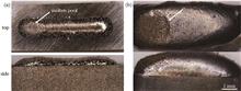
ObjectiveThe heat-treatable aluminum alloy is widely used in the high-speed train body manufacturing industry owing to its low density and high specific strength. In the current high-speed train manufacturing industry, metal inert gas (MIG) welding and friction stir welding are the most commonly used welding techniques for medium-thick aluminum alloys. However, these two welding methods exhibit certain limitations. Laser-MIG hybrid welding combines the advantages of laser and MIG welding, and is a promising welding technology for joining aluminum alloy components. Many investigations have shown that it has several typical technical advantages such as faster welding speed, deeper weld penetration, lower heat input, smaller welding deformation, narrower heat-affected zone, and better mechanical properties. Currently, there are few research reports on laser-MIG hybrid multipass welding for medium-thick aluminum alloys; however, this welding technique is urgently needed in the high-speed manufacturing industry. Laser-MIG hybrid backing welding is a key step in laser-MIG hybrid multipass welding technology and has crucial effects on the weld formation and mechanical properties of weld joints. Therefore, in this study, the laser–MIG hybrid backing welding of a 20 mm thick 6082-T6 aluminum alloy is studied.MethodsLaser-MIG hybrid backing welding is performed on 20 mm thick 6082-T6 aluminum alloy butt joints. The influence of the groove shapes on the arc behavior, droplet transfer, and weld formation is studied using a high-speed camera. The influence of groove form and size on weld formation is analyzed. Based on the optimized groove form, an orthogonal test is used to optimize the welding process parameters, and the primary and secondary orders of influence of the process parameters on weld formation are obtained. Finally, the microstructural characteristics and mechanical properties of the joints are investigated under the optimal parameters.Results and DiscussionsThe U-groove and V-groove have almost similar arc behaviors and droplet transitions, and their droplet transition periods are both 2.5 ms. Compared with the U-groove, the arc length of the V-groove is larger, and it is worth noting that some small welding spatters are found on the V-groove edge. In contrast to the absence of porosity defects on the weld cross section of the U-groove, some porosity defects appear on the weld cross section of the V-groove, which is probably caused by the unstable molten pool and droplet transfer disturbance. In addition, the transition between the weld and upper groove wall is smooth for the U-groove but concave for the V-groove, which is unfavorable for the interlayer cleaning (Figs. 4 and 5). Almost no porosity defects can be observed in the weld seam when the blunt edge height is 10 mm. With an increase in the height of the blunt edge, the number and size of porosity defects in the weld increase sharply (Fig. 6). The main reason is that a larger blunt edge height requires a higher laser power and a smaller laser focusing diameter, which is more likely to cause the keyhole to become unstable and close during the welding process, preventing the pores in the molten pool from escaping and causing porosity defects in the weld seam. An orthogonal test is performed based on the optimized U-groove, and the weld joint is scored using a comprehensive weighted scoring method. The primary and secondary orders of influence of crucial factors on the weld quality from strong to weak are as follows: the welding speed, arc current, laser power, and arc length correction. Because of the lower cooling rate and longer high-temperature residence time in the arc zone, the width of the columnar crystal zone in the arc zone is smaller than that in the laser zone, and the width of the partial melting zone in the arc zone is larger than that in the laser zone (Fig. 7). The stress corrosion resistance susceptibility index of the weld joints is 0.024. The fracture locations of the tensile and stress corrosion resistant specimens occur in the heat-affected zone, the fracture paths are parallel to the fusion line, and their fracture morphologies present typical plastic fracture features.ConclusionsThe optimal groove type is a U-groove with a blunt edge height of 10 mm, which is conducive to obtaining high-quality welds without porosity defects and stable welding processes without spatter. For the laser-MIG hybrid backing welding of a 20 mm thick aluminum alloy butt joint, the primary and secondary orders of the effects of crucial factors on the weld quality from strong to weak are the welding speed, arc current, laser power, and arc length correction, and their optimized values are 0.6 m/min, 6.5 kW, 300 A, and -5 %, respectively. The other welding parameters are as follows: the gap size is 2 mm, laser focusing diameter is 1.0 mm, heat source distance is 3 mm, and defocusing amount is 2 mm. The widths of the columnar and partially melted zones in the arc zone are narrower and wider, respectively, than those in the laser zone. The microhardness values in the weld metal and heat-affected zone are lower than those in the base material, and the lowest microhardness value is obtained far from the fusion line in the heat-affected zone. The weld joints exhibit good stress corrosion resistance, with a stress corrosion resistance susceptibility index of 0.024. The fracture locations of the tensile and stress corrosion resistant specimens occur in the heat-affected zone and the fracture paths are parallel to the fusion line. Their fracture morphologies exhibit typical plastic fracture features.
Oct. 10, 2024Vol. 51 Issue 20 2002101 (2024)
Lei Wu, Yukun Chu, Honggang Yang, and Yunxia Chen
ObjectiveDue to factors involved in the manufacturing process, aluminum alloy materials are prone to various internal welding defects, such as pores, slag inclusion, and incomplete penetration. However, in the DR (digital radiography) image defect detection of aluminum alloy welds, detection accuracy of the model remains insufficient. Thus far, defect detection in DR images is generally determined and located manually. However, manual film evaluation involves a high workload, with low efficiency and other issues such as false and missed detection. With the rapid development of digital image processing technology, deep learning has been widely applied for object recognition. This study proposes a lightweight YOLOv7Tiny based weld defect detection model, YOLOv7TS, to realize DR image defects detection of aluminum alloy welds.MethodsFirst, a TSCODE decoupling head was added to improve the algorithm’s ability to detect small targets. To address the high aspect ratio of incomplete penetration defects and low recall rate, the Upsampling operator was changed to CARAFE to improve the receptive field. Second, for small pixel defects such as pores and slag inclusion, an SPD-Conv convolutional layer was added to enhance the small target detection ability of the model. Finally, a SimAM attention mechanism was added to reduce the depth and width of the model and to improve the overall model performance and ELAN layer.Results and DiscussionsFor pore, slag inclusion, and incomplete penetration, the average precision (AP) of the YOLOv7TS model reached 89.9%, 94.2%, and 96.3%, respectively. Compared with the original YOLOv7Tiny model, average accuracy increased by 8.2, 3.7, and 2.2 percentage points, and the overall accuracy was compared to the original model, mAP@0.5, improved by 4.6 percentage points (Table 1). Meanwhile, the model parameter quantity decreased by 5% compared to the original model. Although the FPS index decreased from 222 to 208, it still meets the target detection speed requirements (Table 2).ConclusionsThis study focuses on key challenges including low accuracy and large model parameters for incomplete penetration defect detection in aluminum alloy weld DR images using the YOLO model. To address these challenges, we improved the YOLOv7Tiny model and proposed a new model: YOLOv7TS. The proposed model effectively improves weld defect detection accuracy. First, the addition of a TSCODE decoupling head increases the average accuracy, however, this increases the number of parameters. Second, by replacing the Upsampling operator with CARAFE and increasing the model receptive field, the average accuracy is improved. Subsequently, the first-layer convolution module is replaced with the SPD-Conv module, and a SimAM attention mechanism is included in the ELAN module. The depth and width of the model were reduced to one-third and half that of the original model, resulting in an average accuracy improvement of 4.6 percentage points and 5% decrease in parameter quantity compared to the original model. Furthermore, the proposed YOLOv7TS model demonstrates higher detection accuracy and smaller parameter size, making it more straightforward to deploy to other terminal devices.
Oct. 11, 2024Vol. 51 Issue 20 2002102 (2024)
Shichao Liu, Shanlin Wang, Yuanmin Zhang, Zhongkui Dai, Wenbin Tu, Yuhua Chen, and Xi Xiao
Compared with other welding technologies, laser welding with a fast cooling speed, small overall deformation after welding, and easy control of the laser beam can yield high-quality welds of complex structural parts. The welding and assembly accuracies can also be improved. However, welded joints often have defects such as pores, cracks, inclusions, and incomplete penetration owing to improper selection of welding parameters, which significantly affect the service life and safety of the aircraft. The microstructure of the welded joint determines its mechanical properties, and the microstructural evolution in the welded joint is closely related to the welding process parameters. In the past, the microstructural evolution of welded joints of titanium alloys was mostly studied by traditional metallography and scanning electron microscope, and the elaborate analysis and understanding of the microstructural evolution of welded joints were limited. In this study, TA15-welded joints are prepared at different welding speeds using laser-welding technology. An electron backscatter diffractometer (EBSD) is used to analyze the microstructure characteristics in each area of the joint, and the relationship between the microstructure and mechanical properties of the joint is investigated in detail, providing a theoretical basis for the rapid application of titanium alloys in laser welding.As shown in Figs. 7 and 8, as the welding speed increases from 1.25 m/min to 2.45 m/min, the hardness and tensile strength of the welded joint initially increase and then decrease; the tensile strength initially increases from 1090.9 MPa to 1140.1 MPa and then decreases to 1093.9 MPa. The increases in the hardness and strength of the welded joint are attributed to the continuous refinement of the grain size; however, the decrease in hardness and strength caused by the increase in the welding speed is attributed to the increase in the β-phase content in the joint. With an increase in welding speed, the elongation of the welded joint decreases from 4.0% to 3.7% and then increases again to 4.0%. The tensile fracture positions of all the welded joints are located in the heat-affected zone.ObjectiveTitanium and its alloys have excellent properties, such as low density, good corrosion resistance, high-temperature performance, high specific strength and stiffness, and good fatigue and creep resistance. Therefore, titanium alloys are used in several structural parts of the aircrafts to lessen their weight and improve their service life. However, an advanced and efficient processing method for these materials has a significant impact on the widespread use of each material.MethodsThe effect of welding speed (1.25, 1.55, 1.85, 2.15, and 2.45 m/min) on the mechanical microstructure and properties of a TA15 titanium alloy laser-welded joint is studied. The microstructure of the TA15 titanium alloy laser-welded joint is analyzed using a scanning electron microscope and an EBSD probe. The samples for the EBSD tests are prepared through electrolytic polishing. The polishing voltage and current are set to 30 V and 0.65?0.90 A, respectively, and the calibration step is 0.15 μm. The microhardness values of the joints are measured using an automatic microhardness tester. The applied load is 200 g and the loading time is 10 s. Tensile tests are conducted on the welded joints using a microcomputer-controlled electronic universal testing machine. The tensile rate is 1 mm/min. The sizes of the tensile samples are shown in Fig. 1.Results and DiscussionsLarge β columnar crystals shown in Fig. 2 are distributed in the weld zone of TA15 titanium alloy laser-welded joints at different welding speeds. With an increase in welding speed, the widths of the weld and heat-affected zones of the TA15 titanium alloy laser-welded joint decrease. As the welding speed increases from 1.25 m/min to 2.45 m/min, as shown in Figs. 4 and 5, the grain size of the weld zone decreases from 3.09 μm to 2.66 μm, and the volume fraction of high-angle grain boundary increases from 91.6% to 95.8%. The grain size of the heat-affected zone decreases from 1.16 μm to 0.94 μm, and the volume fraction of high-angle grain boundary initially decreases from 91.1% to 89.7% and then increases to 94.2%. The β-phase volume fraction of the heat-affected zone initially decreases from 1.09% to 0.64% and then increases to 2.34% as the welding speed increases. The β-phase volume fraction in the weld zone decreases from 0.13% to 0.03% as the welding speed increases.ConclusionsAn increase in welding speed results in a decrease in the welding heat input, resulting in a decrease in the grain size of the weld and heat-affected zones. The contents of large angle grain boundaries and β phase of the weld zone continuously increase and decrease, respectively, as the welding speed increases. However, the contents of the high-angle grain boundaries and β phase in the heat affected zone initially decrease and then increase as the welding speed increases. The tensile strength of the TA15-welded joints first increases and then decreases with increasing welding speed; however, the joint elongation first decreases and then increases with increasing welding speed. The tensile fracture locations of the TA15 titanium alloy laser-welded joints at different welding speeds appear in the heat affected zone. The contents of high-angle grain boundaries and β phase in the heat affected zone initially increase and then decrease, causing the joint elongation to initially decrease and then increase.
Oct. 12, 2024Vol. 51 Issue 20 2002103 (2024)
Qilin Wang, Peng Yao, Yifan Wang, Wanying He, and Chuanzhen Huang
ObjectiveFused silica aspherical cylindrical microlens arrays (ACMAs) are widely used in high-power lasers, mask aligners, large ground-to-air telescopes, and other optical systems that require high precision or operate in extreme environments because of their special geometric characteristics and excellent optical performance. Precision glass molding technology is the first choice for processing optical glass components with high precision, high efficiency, and low cost, compared with traditional array processing methods, such as ultra-precision machining, etching, and laser processing. However, it is difficult to monitor the glass molding process. Hence, finite element simulation is an effective means by which to study the molding process. However, the accuracy of finite element simulation is closely related to the thermo-mechanical and thermo-viscoelastic characteristics of glass. In particular, the thermo-viscoelastic parameters have the most important influence on the accuracy of molding simulation. In this study, we investigate the high-temperature viscoelastic properties of fused silica and establish a corresponding viscoelastic constitutive model. Then, a simulation study of fused silica ACMA precision molding is carried out, and the effects of the process parameters on the maximum stress of the lens are analyzed to provide a reference for fused silica ACMA experiments.MethodsIn this study, the minimum uniaxial creep test (MUCT) of fused silica is carried out, and the creep displacement of a fused silica cylinder is obtained. Based on the generalized Maxwell model and Williams-Landel-Ferry (WLF) equation fitting, the viscoelastic constitutive model and time-temperature equivalent model of fused silica are established. To accurately predict the stress state during the fused silica ACMA molding process, it is necessary to ensure the accuracy of the viscoelastic parameters. Therefore, the obtained viscoelastic parameters of fused silica by MUCT are simulated via the finite element method. Finally, the fused silica ACMA molding is simulated. The large deformation of glass during the molding stage is an important source of stress, and the holding stage can quickly reduce the stress, compared with the annealing stage, owing to the higher temperature. Hence, the effects of several process parameters (molding temperature, molding speed, molding pressure, friction coefficient, holding pressure, and holding time) in the molding and holding stages on the maximum stress of the lens are analyzed to obtain the optimized process parameters.Results and DiscussionsAccording to the MUCT results of fused silica, the viscoelastic constitutive model of fused silica based on the generalized Maxwell model is obtained. It is found that fused silica exhibits significant stress relaxation behavior above the transition temperature and that its shear modulus decreases to about 0.1% in short time [Fig. 5(b)]; the higher the temperature, the faster the relaxation rate. Moreover, based on the WLF equation, the time-temperature equivalent model of fused silica is obtained, and the prediction of the shear modulus of fused silica at different temperatures is achieved. The simulation results of MUCT are also consistent with the experimental results, which shows the accuracy of the viscoelastic parameters. The simulation study of fused silica ACMA molding shows that higher molding temperature can reduce the maximum stress of the lens [Fig. 9(b)] because of the higher relaxation rate and better fluidity of glass. A greater molding speed can cause a greater maximum stress value of the lens (Fig. 10) owing to the swifter deformation of glass, which leads to the inability of the stress to immediately relax. Friction can cause shear stress in the lens and change the stress state of the lens, and the appropriate friction coefficient can effectively reduce the maximum stress of the lens (Fig. 11). The maximum stress of the lens after constant pressure molding is smaller than that after constant molding rate molding [Fig. 12(b)]. Therefore, constant pressure molding is better than constant molding rate molding during fused silica ACMA molding. The maximum stress of the lens can be effectively reduced by applying the holding pressure after molding [Fig. 13(b)], but the mold presents “springback”, and the lower holding pressure cannot eliminate this phenomenon. Choosing the proper holding pressure and holding time can eliminate the mold “springback” when reducing the maximum stress. After the molding and holding stages, the maximum stress of the lens is 0.9693 MPa.ConclusionsIn this study, the high-precision stress state simulation of fused silica ACMA molding is investigated. Based on the MUCT and generalized Maxwell model, the viscoelastic constitutive model of fused silica is established. Fitting the WLF equation based on the relationship among the shear modulus values of fused silica at different temperatures, the time-temperature equivalent model of fused silica is established. The simulation results of MUCT show that the obtained viscoelastic constitutive model has high accuracy. A finite element simulation is conducted on the fused silica ACMA molding by inputting the obtained viscoelastic parameters of fused silica. The effects of different process parameters during the molding and holding stages on the maximum stress of the lens are analyzed. Moreover, on the premise of a downward displacement of 1.5 mm, the optimized process parameters are obtained. That is, the constant pressure mode is selected, the molding temperature is set to 1400 ℃, the friction coefficient is set to 0.3, the holding pressure is set to 400 N, and the holding time is set to 100 s. After the molding and holding stages, the maximum stress of the fused silica ACMA is 0.9693 MPa, which provides a reference for fused silica ACMA molding experiments.
Oct. 25, 2024Vol. 51 Issue 20 2002104 (2024)
Haojie An, Jinshi Wang, and Fengzhou Fang
ObjectiveSilicon carbide (SiC) is a high-performance third-generation semiconductor material that is poised to meet the growing demand in the optoelectronic field. Further exploration of SiC processing at atomic and close-to-atomic scales is of great importance for both fundamental science and industrial applications. The hard and brittle nature of SiC renders traditional methods, such as ultraprecision machining, impractical for achieving high-quality surface treatments. Although some approaches, such as ion implantation or laser heating, can improve the machinability of hard and brittle materials, achieving high-quality processing remains elusive. Laser direct writing emerges as a potential solution for atomic- and close-to-atomic-scale manufacturing (ACSM). However, there is a lack of understanding regarding the laser-material interactions at the atomic and close-to-atomic scales. A hybrid two-temperature model-based molecular dynamics (TTM-MD) method can reveal the interactions from an atomic perspective; however, the one-dimensional (1D) TTM-MD model ignores the lateral propagation of heat and stress, which limits the understanding of surface modification and ablation. In this study, a three-dimensional (3D) TTM-MD model is developed to study the femtosecond laser ablation of 4H-SiC at varying fluences. The atomic trajectories, temperature fields, structural morphologies, and ablation products are analyzed. We hope that the 3D TTM-MD model will be helpful in the material processing of femtosecond lasers at the atomic and close-to-atomic scales.MethodsA 3D profile of the absorption of laser energy by materials is obtained by analyzing a Gaussian beam. A 3D TTM-MD code is developed using the open-source software LAMMPS. The coupling of the TTM and MD is achieved by using a coarse-grained electron temperature grid. The dimensions of the simulation box are 1000 ?×502 ?×500 ?. The size of the laser beam is 200 ?, and the absorption depth is set to 50 ?. The femtosecond laser ablation of 4H-SiC is simulated based on this model, and the influence of the laser fluence on laser ablation is also discussed. Periodic boundary conditions are employed in all three directions. The interactions of the atoms in the simulation are described using the Tersoff potential. The time step is set to 0.5 fs. The phase-explosion threshold temperature of 4H-SiC is calculated through a constant-pressure MD simulation in which a system containing 2880 atoms is heated at a rate of 2 K/ps in an isothermal-isobaric (NPT) ensemble. After the simulations, the atomic configurations are extracted and analyzed for discussions on the material removal depth, modification layer thickness, and ablation plumes.Results and DiscussionsOwing to the rapid deposition of laser energy, an initial conical elevation structure forms in the irradiated zone. This is similar to the Gaussian energy distribution of a laser beam (Fig. 2). The ejection path of the ablation plume exhibits a hemispherical shape, and clusters or small droplets are deposited around the laser-affected zone in subsequent processes. This is a major factor in the contamination of clean surfaces during laser processing. At the end of the simulation, a volcano-shaped ablation crater forms on the material surface. The temperature field distribution during the ejection of the ablation plumes (Fig. 3) indicates intense laser absorption and thermal diffusion. The dimensions of the ablation crater, including the diameter, depth, and thickness of the modification layer, exhibit an upward trend concurrently with the enhancement of the laser fluence (Fig. 4). In addition, a constant-pressure MD simulation provides the threshold temperature of the phase explosion and the size distribution of the clusters after explosive boiling (Fig. 5). At higher fluences, the ablation products show higher proportions of clusters with smaller sizes, and the vaporization process is more pronounced. The laser-affected zone satisfies the temperature condition of the phase explosion, and the cluster size distributions in the ablation plumes are consistent with those observed after explosive boiling (Fig. 6). These results provide evidence that supports the phase-explosion mechanism.ConclusionsA 3D TTM-MD model is developed to study the interaction between lasers and matter. This model is employed to investigate the modification and ablation of the surface of 4H-SiC by femtosecond laser irradiation at the atomic and close-to-atomic scales. At laser fluences of less than 50 mJ/cm2, both laser-induced removal and modification are observed on the surface. At a laser fluence of 20 mJ/cm2, the expansion of the modification layer in the beam center compensates for the structural height change that is induced by the removal owing to vaporization, and a bowl-shaped structure forms, owing to the expansion of the edge caused by phase transition. At a laser fluence of 10 mJ/cm2, the laser-material interaction is dominated by a crystalline-to-amorphous phase transition with no observable material removal and a modification layer thickness of only 2 nm. Furthermore, the analysis of the temperature field and ablation plumes in the 3D TTM-MD simulations indicates that the laser ablation process is primarily attributable to the phase explosion mechanism. These simulation results prove the surface processing capabilities of the femtosecond laser on 4H-SiC at the atomic and close-to-atomic scales and thereby provide theoretical guidance for material processing in the field of ACSM using a femtosecond laser. It is expected that femtosecond-laser-induced phase transformation combined with acid etching or polishing technologies can be used to remove materials at the atomic and close-to-atomic scales, which makes it an important technological approach in ACSM.
Oct. 12, 2024Vol. 51 Issue 20 2002401 (2024)
Yingming Zheng, Zuo Cao, Jiawei Huang, Haiqing Liao, Yajun Huang, Jiangyou Long, and Xiaozhu Xie
ObjectiveLiquid-transporting functional surface structures play important roles in lithium-ion batteries, heat transfer, and chemical reactions. Grooves are excellent structures for liquid transport and their hydrophilic properties can be improved by generating CuO nanosheets and nanograss structures on their surfaces. However, as the functional surface structure becomes more precise, the mechanism by which the micro- and nanotextures of the surface affect its hydrophilic properties changes. Studies have revealed that micrometer-thick structures such as nanosheets and nanograss within small-scale grooves hinder liquid transport, resulting in a deterioration in liquid transport functions. In addition, the enhancement of the liquid transport performance by reducing the liquid flow resistance has been widely studied. Current efforts to reduce the flow resistance have primarily focused on superhydrophobic surfaces, which are not suitable for hydrophilic application scenarios. Laser-induced periodic surface structures (LIPSSs) are nanoscale structures that form highly periodic, ordered, and directionally controllable patterns, which can enhance the small-scale groove capillary force and drag reduction performance. In this work, the preparation of continuous clear periodic surface structures on a groove surface is realized by studying the effect of different laser parameters on the formation of LIPSSs. Capillary diffusion experiments are carried out on the laser-induced periodic structures on the groove surface. By analyzing the effect of the different composite angles of the LIPSS in the grooves on the capillary diffusion performance, we aim to identify the structures that enhance the liquid transport performance in small-scale grooves and to understand the relationship between LIPSSs and liquid flows.MethodsInitially, the formation of copper fragments is suppressed by modulating an ultrafast laser, enabling the creation of smooth V-shaped grooves on the surface of a copper sheet by removing oxides through acid washing after laser ablation. Subsequently, the effects of different laser parameters on the formation of the LIPSSs are investigated to realize the preparation of clear periodic surface structures on the groove surface. Then, surface morphology and geometry are analyzed using scanning electron microscope and laser confocal microscope. The effect of LIPSSs on the liquid flow in grooves with different depth-to-width ratios is investigated via capillary diffusion experiments to evaluate the enhancement effect of LIPSS on the capillary diffusion performance. Additionally, the relationship between the LIPSS composite angle and liquid flow resistance is also investigated using capillary diffusion experiments with grooves featuring different LIPSS angles. In addition, the mechanism behind this action is investigated by analyzing the state of the capillary flow of liquid droplets in the grooves.Results and DiscussionsLIPSSs are prepared on copper surfaces with a contact angle of 14.7° to enhance the surface hydrophilic properties (Fig. 1). An LIPSS prepared with equivalent pulse number (N=160) and energy density (F=0.26 J/cm2) works best (Fig. 2). By tuning the laser parameters, clear and intact LIPSSs with different angles can be prepared in grooves with different depth-to-width ratios (Figs. 3 and 4). The incorporation of an LIPSS in the grooves enhances the capillary diffusion performance, and the effect is more significant in grooves with a small depth-to-width ratio. Smooth grooves with a width and depth of 50 μm and 12 μm, respectively, do not exhibit diffusion properties, and diffusion occurs only with the addition of an LIPSS (Fig. 5). The diffusion properties of the 25 μm and 50 μm deep grooves with 0° LIPSSs show 30.8% and 29.4% enhancement, respectively, over those of smooth grooves. The compound angle of the LIPSS in the groove affects the flow of liquid.The groove with 0° LIPSS has the best capillary diffusion properties and the groove with 90° LIPSS has the smallest capillary diffusion coefficient (Table 1).ConclusionsIn this study, we investigate the effect of an ultrafast laser on LIPSSs, resulting in the realization of clear periodic surface structures with different angles within the grooves. The solid surface wettability and capillary diffusion performance can be enhanced by increasing the surface roughness and decreasing the Wenzel contact angle of the LIPSSs within the grooves, and the effect of the LIPSS is more significant in small-scale grooves. Furthermore, the angle between the LIPSS and groove direction affects the flow resistance of the liquid, and structures with a smaller angle between the LIPSS and groove direction exhibit superior capillary diffusion performance owing to small energy barriers and the ability to provide additional capillary forces. In the grooves with a width and depth of 50 μm and 12 μm, respectively, capillary diffusion occurs only in grooves with 0° LIPSSs. Furthermore, diffusion properties of the 25 μm and 50 μm deep grooves with 0° LIPSS exhibit 30.8% and 29.4% enhancement, respectively, compared with those of smooth grooves.
Oct. 12, 2024Vol. 51 Issue 20 2002402 (2024)
Chengyuan Gao, Wenhai Gao, Yang Liao, Juan Du, Shaoming Xie, Cong Chen, Ke Liu, Yujie Peng, and Yuxin Leng
ObjectiveQuartz glass is widely used in the semiconductor, optics, and biomedicine fields, among others. However, because of its high hardness and brittleness, the processing accuracy and edge quality of traditional methods are limited. As an advanced processing technology, which has developed rapidly recently, femtosecond laser machining has the advantages of high precision and a small heat-affected zone, demonstrating its potential for high-end quartz glass processing. Unfortunately, currently, the removal rate of femtosecond laser ablation is low, which limits its industrial application. To achieve high-efficiency scribing on fused silica using a femtosecond laser, a composite scanning strategy that combines high-speed galvanometer scanning and slow direct writing with an X-Y translation stage is proposed in this study. We believe that this technique will significantly improve the efficiency of quartz glass laser processing and enable the flexible control of the cross-sectional geometry of laser-ablated microgrooves.MethodsFirst, a quartz glass sample is placed on a 2D motorized translation stage. A circularly polarized femtosecond laser with a wavelength of 1064 nm and pulse duration of 800 fs is guided into a galvanometer scanner. After passing through the galvanometer and 4f system, the laser is focused on the quartz glass surface using an objective lens. To implement high-efficiency femtosecond laser scribing, a 2D translation stage is used to realize laser scribing along a predetermined trajectory, while the galvanometer scanning system enables dynamic oscillatory scanning of the laser focus spot around the trajectory. By maintaining the same laser irradiation fluence (laser power and irradiation time) for each oscillating scan, the effects of the oscillating scanning path, scanning amplitude, and stage translation speed on the laser-ablated microgrooves are investigated in detail. Additionally, an oscillatory scanning path is used to change the laser energy deposition distribution and thus control the cross-sectional geometry of the laser-ablated microgrooves.Results and DiscussionsCompared with its counterpart without oscillatory scanning, the depth and width of the microgrooves produced via dynamic oscillatory scanning with four different paths are substantially increased (Fig. 2). The reasons for this can be summarized as follows: 1) the dynamic oscillatory scanning increases the microgroove width and relieves the sidewall shielding effect; 2) by virtue of the high-speed scanning of the galvanometer, the laser spot dwell time is very short, which not only suppresses the plasma shielding effect but also makes the ablated debris smaller and easier to eject; 3) the optical pressure generated by the high-speed laser scanning can aid debris ejection and reduce debris buildup in the microgroove. Additionally, the surface morphologies of the microgrooves with and without oscillatory scanning are discussed (Fig. 3). It can be seen that the oscillatory scanning process has a smaller heat-affected zone and recast layer, which can be attributed to the spatial dispersion of laser pulses over a large area. As the stage translation speed increases from 0.1 mm/s to 2.0 mm/s, the microgroove depth using four different oscillatory scanning paths decreases from ~300 μm to ~100 μm, while those without oscillatory scanning remain constant at ~20 μm. The microgroove depths produced by the concentric-circle and cross oscillatory scanning have a slower decline, which can be attributed to the laser spot overlapping being more homogeneous when the scanning is implemented in both the parallel and perpendicular directions (Fig. 4). As the concentric-circular oscillatory scanning amplitude increases, both the microgroove depth and depth-to-width ratio initially increase and then decrease (Fig. 5). When the dynamic oscillatory scanning paths are modified, the cross-sectional geometries of the microgrooves change from V-shape to U-shape, which can be attributed to the change in the spatial distribution of the laser pulse (Fig. 6).ConclusionsIn this study, a dynamic oscillatory scanning strategy that combines high-speed scanning with a galvanometer scanner and slow direct writing using a translation stage is proposed. Compared with its counterpart without oscillatory scanning, the inscription depth is improved and the generation of recast layers is effectively suppressed with the dynamic oscillatory scanning strategy. Experimental results show that the microgroove depth decreases as the translation speed increases, while the microgroove depths by concentric-circle and cross oscillatory scanning have a slower decline. As the scanning amplitude increases, both the microgroove depth and depth-to-width ratio initially increase and then decrease. Additionally, the dynamic oscillatory scanning strategy enables the flexible control of the cross-sectional geometry of laser-ablated microstructures by changing the oscillatory scanning path. Femtosecond laser surface scribing assisted by dynamic oscillatory scanning opens up new opportunities for the high-efficiency and high-quality processing of various surface microstructures.
Oct. 12, 2024Vol. 51 Issue 20 2002403 (2024)
Mengyao Niu, Xinyi Wu, Fanchun Bin, Qi Duan, Teng Li, and Meiling Zheng
SignificanceIn biology, a topological structure refers to the specific spatial arrangement of the internal organization of a cell or organism, including factors such as the relative positions of the cells, nature of the connections, shape, and size. Topological structures can regulate the behaviors of cells and affect their biological processes, such as growth, differentiation, and migration, which are crucial for the formation of tissues and organs as well as the development of overall structure and function. Hence, they are capable of providing a new direction for future biomedical research with far-reaching implications for human health and disease treatment.Laser micro-nano fabrication technology is an advanced manufacturing technology that enables the fabrication of micro-nano scale structures by using laser beams for the precise fabrication of materials. The high-precision, high-resolution, and non-contact characteristics of laser fabrication technology make it possible to design specific topological structures.By precisely controlling the energy and focus of the laser, laser fabrication technology can fabricate a variety of topological surfaces on demand, and it shows unique potential in regulating cell proliferation, differentiation, migration, and adhesion. Intensive research in this field is expected to provide advanced technological tools as well as accelerate innovation and development in biomedical engineering.Many advances have been made in recent years regarding the fabrication of topological structures using laser fabrication techniques and their applications in cell biology. However, there are still challenges in the fabrication of large-area, high-complexity structures and the mechanisms of topological structures on different cell types. Therefore, it is necessary to summarize the existing relevant research progress to gain a more comprehensive understanding of the problems in this field, as this will be instructive for the future direction of the field.ProgressFirst, the design elements of topological structures and their regulation rules on cell behavior are discussed to provide a theoretical basis for laser fabrication technology in the fabrication of topological structures. Second, the working principle and characteristics of laser processing technology are introduced, and its advantages of high controllability and precision lay the technical foundation for its application in cell biology. Finally, through an in-depth study of the application of laser processing topologies in simulating cellular microenvironments, cellular localization and orientation, and tissue repair and regeneration, the great potential of these technologies for application in cellular, tissue, and biomedical engineering is revealed. Zandrini et al. used multifocal two-photon polymerization to produce stem cell culture substrates, that were able to stimulate cell proliferation while maintaining cell stemness without the addition of toxic and harmful additives. The use of spatial light modulators allows for the parallelization of this technique: in combination with a fast linear bench, 3D stem cell scaffolds can be prepared via two-photon polymerization, which is particularly suitable for the preparation of porous structures and offers a good structural polymerization and time savings with only minor adjustments of the parameters. Schnell et al. employed a femtosecond laser nanofabrication technique to produce microtextures on a Ti6Al4V surface and found a clear correlation between the surface properties (wettability and nano/microtexture) and cell adhesion. The growth and spreading of human MG-63 osteoblasts were inhibited on rough microstructures with deep cavities. Both nanostructured and sinusoidal microstructured surfaces showed improved cell adhesion and growth, regardless of surface hydrophilicity. Liang et al. fabricated a bionic cardiovascular scaffold for in vivo reendothelialization by using a femtosecond laser to fabricate a bionic surface pattern of vascular smooth muscle cells (VSMCs) on 316L cardiovascular scaffolds implanted into the iliac arteries of rabbits. The bionic surface pattern closely matched the morphology of VSMCs and effectively promoted the adhesion, proliferation, and migration of human umbilical vein endothelial cells. The patterned surface demonstrated a significant enhancement in reendothelialization.Conclusions and ProspectsIn recent years, the laser fabrication of topological structures has made progress in cell biology application. For example, it is used to fabricate topological structures that simulate cellular microenvironments for cell cultures, achieve cell guidance and localization, and promote tissue repair and regeneration. Laser fabrication technology provides a novel tool and method for cell biology research and brings infinite possibilities for the future of biomedical engineering. However, the realization of large-area and high-complexity structure fabrication is still a challenge to be solved. The mechanisms of the laser fabrication of materials, such as the specific relationships between fabrication parameters and material properties, surface physical changes, and surface chemical changes, are not known. Furthermore, the mechanisms of the effects of various types of laser-processed topological structures on different types of cells are still unclear. In-depth studies on the interactions between cells and topological structures are necessary to establish comprehensive biocompatibility and effect evaluation criteria. In the future, the application of laser-processed topological structures for in vivo therapy also needs to address the biocompatibility of the materials, effect of the laser on tissue, and long-term stability of the therapeutic effect.
Oct. 13, 2024Vol. 51 Issue 20 2002404 (2024)
Xiankai Meng, Han Zhang, Fuyang Song, Kun Wang, and Jianzhong Zhou
ObjectiveTi6Al4V alloys are used extensively in the aerospace industry. However, with the ongoing development of aerospace technology, higher demands are being placed on load-bearing capacity, service life, and reliability. Laser shock peening (LSP) is a novel and ecofriendly surface modification technique. However, its effectiveness for strengthening the surfaces of metals with high hardness and strength, such as Ti alloys, is limited. Dual-pulse laser shock peening (DPLSP) enhances the strengthening effect by using delayed dual-laser pulses to increase the pressure and duration of laser-induced shock waves. In this study, a Ti6Al4V titanium alloy is subjected to DPLSP. The microstructure evolution and tensile property changes of the specimens after single-pulse laser shock peening (SPLSP) and DPLSP treatments are compared and analyzed using methods such as microscopic structure observation, phase analysis, microhardness testing, tensile testing, and fracture morphology observation. Furthermore, the mechanism of the DPLSP process is elucidated.MethodsLaser-processed samples are cut into standard tensile test samples via wire cutting (Fig. 1), and they are subjected to dual-sided DPLSP using a delayed dual-pulse laser with a time delay of 13.5 ns that is achieved through polarization spectroscopy and a mirror array (Fig. 2). First, the microstructures of the surface layers of the samples are observed using a transmission electron microscope. Second, the phase structures of the samples are examined using an X-ray diffractometer. Furthermore, the microhardness of the surface and cross-section of the samples after different treatments are measured using a microhardness tester. Room-temperature tensile tests are performed using an electronic universal testing machine. Finally, the fracture morphology is observed using a scanning electron microscope.Results and DiscussionsThe results of the microstructural analysis of the surface layer show that after the DPLSP treatment, the dislocation density and complexity in the sample surface layer significantly increase and the grains are noticeably refined (Figs. 4‒6). The X-ray diffraction results indicate that after SPLSP treatment, the (101) diffraction peak position of the sample shifts from 40.44° to 40.5°, and the full width at half maximum (FWHM) widens from 0.12° to 0.21°. After the DPLSP treatment, the (101) diffraction peak position shifts farther to the right, reaching 40.64°, and the FWHM widens to 0.25° (Fig. 7). The microhardness results show that after the SPLSP and DPLSP treatments, the surface microhardness values are 376.2 HV and 414.2 HV, respectively, and the affected layer depths are 400 μm and 550 μm, respectively. Tensile performance tests reveal that after the SPLSP and DPLSP treatments, the tensile strengths are 956.31 MPa and 1002.33 MPa, respectively, and the elongations are 14.61% and 13.48%, respectively. The fracture morphology results show that river pattern cleavage planes appear in the DPLSPed sample fractures. In the near-surface layer, the overall number and size of the dimples are further reduced. However, there is an increase in the localized density of the honeycomb-like dimples as well as an increased number of cleavage planes.ConclusionsIn this study, the surface of a Ti6Al4V alloy is strengthened by using DPLSP. A systematic study on the microstructure, phase composition, microhardness, tensile properties, and fracture morphology is conducted. This study compares and analyzes variations in the tensile properties of untreated, SPLSPed, and DPLSPed samples to reveal the mechanism of DPLSP on a Ti6Al4V titanium alloy. The main conclusions are as follows. 1) Because of the higher peak pressure and duration of the shockwave, DPLSP induces an increase in the dislocation density compared with SPLSP and dislocation walls, dislocation cells, and sub-boundaries appear. This process, combined with mechanical twinning, leads to the formation of many complex microstructures and results in the significant refinement of the original coarse grains. Additionally, owing to the dual-sided peening, a composite structure of fine-coarse-fine grains is formed in the depth direction. 2) The high-density dislocations and refined grains induced by DPLSP increase the surface microhardness of the Ti6Al4V titanium alloy samples to 414.2 HV, which is an improvement of 10.1%, compared with that by SPLSP. The depth of the hardened layer is approximately 550 µm, which is a 37.5% increase over that by SPLSP. 3) The average tensile strength and elongation of the DPLSPed samples are 1002.33 MPa and 13.48%, respectively. The former shows a 4.81% increase over that of the SPLSPed samples, whereas the latter shows a 1.79% decrease. During the tensile process, the strain gradient occurs near the interface between the coarse-grained and fine-grained layers, leading to a significant increase in the tensile strength of the material while maintaining a good elongation rate.
Oct. 25, 2024Vol. 51 Issue 20 2002201 (2024)
Chengrun Ye, Jianyu Sun, Yingbin Long, Xujie Zhao, Zenghuan Zhang, Zhengrong Yu, Yujie Peng, and Yuxin Leng
ObjectiveThe TC4 titanium alloy is the earliest and most widely used titanium alloy in aviation and aerospace structures. However, the TC4 titanium alloy exhibits high sensitivity to notches, which decreases its fatigue resistance and leads to fatigue fracture during use. The detail fatigue rating (DFR) is a parameter that is commonly used in civil aviation to assess the fatigue resistance of the TC4 titanium alloy. Laser shock peening (LSP) is a novel strengthening method that has been proven to effectively improve the fatigue life of the TC4 titanium alloy. Previous research on LSP primarily assesses the fatigue resistance of the TC4 titanium alloy by using methods such as analyzing the S-N (residual stress versus fatigue life) curve of the residual stress, examining fracture surfaces, or conducting finite element simulations. However, there is a limited number of studies that directly investigate the enhancement of TC4 fatigue resistance via LSP based on the DFRcutoff value. In addition, during the LSP of TC4 samples, plasma easily penetrates the water flow layer in the notch area, and the laser directly impacts the surface of the TC4 notch area, which leads to the ablation and damage of the titanium alloy surface. This, in turn, reduces the DFRcutoff value and service life of the titanium alloy. Therefore, this article presents a novel LSP strategy that utilizes a discontinuous composite path, consisting of a C-shaped path and a matrix, with a zero overlapping rate. The objective is to investigate the potential of LSP to enhance the fatigue resistance of TC4 materials by considering the DFRcutoff value. This study serves as a valuable reference for future research on the improvement of fatigue resistance in aviation TC4 alloys via LSP.MethodsFirst, the TC4 alloy was fabricated into specimens with a gage section geometry of 290 mm×40 mm×7 mm. Subsequently, the specimens underwent a laser shock peening treatment. The surface roughness of the TC4 alloy treated by LSP was measured using a PROTO Proflometer LP200 laser profilometer. The microstructure and morphologies were characterized using an FEI Talos F200X G2 (200 kV) for focused ion beam scanning electron microscopy (FIB-SEM). The residual stress was tested by using a PROTO LXRD X-ray diffractometer with the sin2 ψ method. A fatigue life test was performed using an SDZ-0100 fatigue tester at a frequency of approximately 20 Hz, following the guidelines of HB 7110—1994.Results and DiscussionsThe results indicate that there is no significant difference in surface roughness between the areas treated with LSP and the untreated areas for the TC4 titanium alloy when the LSP is conducted at a power density of 10 GW/cm2 with varying overlap rates of 0, 25%, and 50%. The average residual compressive stress on the surface of the sample after impact strengthening reaches its peak and varies as the laser power density increases at the same overlapping rate. The residual compressive stress increases with an increase in the overlapping rate under fixed laser power density conditions. The maximum value of the residual compressive stress is reached when the spot overlapping rate increases from 0 to 25%. The DFRcutoff values of the samples increase with the increase in laser power density owing to LSP treatment at 8 GW/cm2, 10 GW/cm2, and 12 GW/cm2, compared with the DFRcutoff values of untreated TC4 samples. The DFRcutoff value increases by 20.76%, compared with the untreated TC4 sample. This is mainly because the laser energy absorbed on the surface of the TC4 sample increases with the increase in laser energy. As a result, the shock wave generated by the laser induces greater plastic deformation and grain refinement on the surface of TC4, which leads to the formation of more dislocations. These dislocations effectively counteract the normal stress and inhibit the generation and propagation of cracks during cyclic loading. Consequently, this leads to a reduction in the local effective load of the sample and thereby enhances the fatigue resistance of the TC4 sample after the LSP treatment and results in a higher DFRcutoff value.ConclusionsIn this study, a novel approach is employed to systematically investigate the effect of LSP on the cutoff value of the detail fatigue rated strength of the aerospace titanium alloy TC4. This approach involves a unique combination of a rectangular path and a C-shaped path, which together form a discontinuous composite path. The investigation focuses on the impact of a non-continuous composite path with a zero overlapping rate on the surface treatment of LSP. The results indicate that a laser power density of 12 GW/cm2 results in a maximum residual compressive stress of -669.67 MPa, with a corresponding compressive stress depth of 0.8 mm. Additionally, fatigue testing reveals that setting the laser power density to 12 GW/cm2 leads to a 20.76% increase in the DFRcutoff value of the TC4 titanium alloy, compared with its original value.
Oct. 13, 2024Vol. 51 Issue 20 2002202 (2024)
Wenzhe Hu, Guanyin Song, Chenyu Li, Xueyan Zhang, Shuzhen Nie, Liang Qu, and Xiaolong Liu
ObjectiveCultural relics suffer from corrosion and damage caused by the fragile composition of the material and the surface pollutants resulting from environmental changes. Laser cleaning, characterized by high efficiency, environmental friendliness, and strong controllability, is an effective method for removing surface pollutants without harming the relics, rendering it suitable for cleaning various types of cultural relics. Recognizing the advantages of ultrashort pulse lasers in the realm of cultural relic cleaning, along with the critical role of the laser wavelength in this process, two primary research focuses have emerged: picosecond and multi-wavelength laser cleaning of cultural relics. This paper addresses the requirements for applying laser cleaning to stone cultural relics. Comprehensive numerical simulations and experiments were conducted on the removal of surface contaminants using picosecond lasers at wavelengths 1064, 532, and 355 nm. Concurrently, a variety of real-time and offline detection methods were employed in a coordinated manner to analyze the effects of picosecond laser cleaning at these three wavelengths, considering aspects such as sample surface morphology, roughness, and elemental content. The ultimate goal was to determine the most suitable wavelength parameters for cleaning stone cultural relics.MethodsTo address the specific demands for laser cleaning of stone cultural relics, in this study, a systematic investigation is conducted through numerical simulations and experimental research on the surface pollutants of stone cultural relics treated with a picosecond laser at three wavelengths: 1064, 532, and 355 nm. A two-temperature model is applied to simulate the interaction between picosecond laser pulses of the three wavelengths and surface contaminants, considering differences in the ablation process and depth at the same laser energy density. Building on this foundation, the damage threshold of the picosecond laser at three wavelengths and the cleaning thresholds for surface pollutants on stone cultural relics under specific conditions are measured. In the experiment, a coaxial charge-coupled device (CCD) is applied for real-time monitoring and control of the laser-cleaning process. The surface roughness and elemental content before and after laser cleaning are measured using a confocal microscope and a fluorescence spectrometer, respectively.Results and DiscussionsThe damage thresholds were 0.26±0.06, 1.45±0.06, and (2.1±0.08)J/cm2 at the wavelengths of 1064, 532, and 355 nm, respectively (Fig. 5), and the cleaning thresholds were 0.198±0.033, 0.573±0.114, and (0.739±0.249)J/cm2 respectively under specific conditions (Fig. 7). For an energy density of 2 J/cm2 pulse, the laser ablation depths were respectively 171, 106, and 62 μm for 1064, 532, and 355 nm laser pulses, and in numerical simulations, the ablation depths were 164, 104, and 58 μm respectively for the same energy density of 2 J/cm2 pulse (Fig. 4). The experimental results are similar to those obtained by numerical simulations. Thermal ablation plays a major role in the surface ablation of contaminant materials by picosecond pulsed laser at this energy density, whereby the sample surface undergoes continuous cleaning utilizing picosecond lasers at these three wavelengths. Real-time monitoring via a CCD system was utilized for online observation until no alterations in surface contaminants were detected. Subsequently, a comparative analysis was performed on various factors, including surface morphology, roughness, and elemental content after cleaning. The objective was to evaluate the variations in cleaning efficiency among lasers of different wavelengths. The surface morphology (Fig. 8), roughness, and elemental content of the pollutants before and after laser cleaning at different wavelengths were compared and analyzed. The experimental results show that the surface roughness of the sample after laser cleaning at the three wavelengths of 1064, 532, and 355 nm was 13.71, 30.816, and 20.789 μm, respectively (Fig. 9). The content of S, the main component of the surface contaminants after laser cleaning at the three wavelengths, was 0.41%, 4.09%, and 1.15%, respectively (Table 4). The Fe content on the surface of the sample after laser cleaning at the three wavelengths was 0.42%, 2.13%, and 4.16%, respectively (Table 4).ConclusionsThe results obtained from experiments and numerical simulations are approximate. When irradiating the surface with a picosecond pulse laser at the energy density of 2 J/cm2, thermal ablation plays a primary role in ablating contaminants from the surface of the material. The cleaning thresholds, efficiency, surface roughness, and elemental content were used for a comparative analysis of laser cleaning at the three wavelengths of 1064, 532, and 355 nm, thereby demonstrating that the 1064 nm laser had the smallest damage and cleaning thresholds under specific conditions, as well as the highest cleaning efficiency. The surface roughness of the sample was the smallest after 1064 nm wavelength laser cleaning, and the contents of S and Fe, the main components of the surface contaminants, were the least. Considering various factors, including the laser cleaning threshold, cleaning efficiency, post-cleaning surface roughness, and contaminant element content, the 1064 nm wavelength laser demonstrated the lowest cleaning threshold, highest efficiency, and most thorough cleaning. Overall, its cleaning performance surpassed that of lasers with 532 nm and 355 nm wavelengths under the same parameters.
Oct. 14, 2024Vol. 51 Issue 20 2002203 (2024)
Jiajun Fu, Chao Liu, Xinrong Song, Zhe Shi, Xiaozhe Guo, Ziang Li, and Qinghua Wang
ObjectiveSilicon carbide (SiC) is widely used in fields such as functional ceramics, power electronics, and photovoltaics owing to its excellent physical and chemical properties. However, the intrinsically hydrophilic properties of SiC make it easy to adsorb dirt. Moreover, the SiC surface can readily freeze in low-temperature environments, which undermines the performance of SiC components and results in significant economic losses. Therefore, the extension of SiC applications has been limited owing to these drawbacks. Traditional preparation of superhydrophobic surfaces includes coating, chemical etching, and electroplating. However, most of these processes have distinct restrictions owing to the use of hazardous chemicals, complex processing, low processing efficiency, high requirements for the nature and size of the material, and non-environmental friendliness. To address these problems, we obtain a superhydrophobic surface by modifying the surface of SiC using a laser-silicone oil-heat treatment composite process combined with a bionic design. This superhydrophobic SiC surface presents excellent self-cleaning, anti-icing, and mechanical durability properties. Hence, the obtained surface is expected to expand the application prospects of SiC.MethodsThe surface texturing shape is designed and optimized using the microstructural characteristics of natural loach and shark skins (Fig. 1). The composite process (Fig. 2) includes the following steps: First, the SiC surface is processed using laser surface processing to construct a regular array with multilevel micro/nanostructures which result in a wettability shift from hydrophilicity to superhydrophilicity. Subsequently, a pre-configured mixed solution consisting of silicone oil and isopropanol (IPA) of approximately 50 μL is dripped onto the superhydrophilic surface. After the solution completely infiltrates the laser-processed area, the superhydrophilic surface is heated on a heating plate at 200 ℃ for 10 min, followed by ultrasonic cleaning with isopropanol and air-drying. Subsequently, the superhydrophilic surface is transformed into superhydrophobicity. Furthermore, the physical and chemical properties of the surface are tested. Laser confocal microscope and scanning electron microscope are employed to characterize the micro/nanostructure of the superhydrophobic SiC sample surface. The chemical element composition of the surface is analyzed using X-ray photoelectron spectroscopy. The contact angle is measured using a contact angle measuring instrument with a high-resolution complementary metal-oxide-semiconductor transistor (CMOS) camera. Finally, chemical stability, self-cleaning, anti-icing, and sandpaper cyclic friction experiments are designed to evaluate the long-term stability, self-cleaning performance, anti-icing performance, and friction and wear performance of the superhydrophobic SiC samples, respectively.Results and DiscussionsBy adjusting the laser processing parameters, periodic biomimetic structural surfaces with different densities and roughness are prepared (Fig. 3). The experimental results show that the laser parameters are important for forming micro/nanostructures. Furthermore, the micro/nanostructures processed using laser are composed of a combination of densely grown oxide nanopapillae structure and “fence” structure (Fig. 4). Surface chemical analysis shows that the contents of C and O elements are important for the regulation of wettability. A large number of nonpolar carbon-containing hydrophobic groups (—CH2—,—CH3, C=C) are deposited on the laser-processed surface after silicone oil-heat treatment, and the full deposition of Si elements on the surface further strengthens the hydrophobicity of the laser processed surface after heat treatment (Fig. 5). The wettability results indicate that the untreated SiC surface (with a contact angle of 70.3°±1.2°) after laser processing transitions to the Wenzel state (with a contact angle of 0°). Subsequently, the wettability of the SiC surface shifts from superhydrophilicity to hydrophobicity via silicone oil treatment and simultaneously, the wetting state of the surface transforms from Wenzel state to C-B state. After IPA cleaning, the hydrophilic surface transforms into superhydrophobicity (Fig. 6). By changing the laser processing parameters, the wettability of the SiC surface can be adjusted, and superhydrophobicity is guaranteed when using the laser processing parameters in the following range: scanning speed of 20?200 mm/s and scanning spacing of 100?150 μm (Fig. 8). Performing chemical stability, self-cleaning, anti-icing, and sandpaper cyclic friction experiments demonstrate that the superhydrophobic SiC samples exhibit excellent long-term stability, friction and wear resistance, self-cleaning, and anti-icing properties (Figs. 9?12).ConclusionsIn this study, by mimicking the microstructure characteristics of loach and shark skins in nature, multilevel micro/nanostructures are successfully fabricated on the surface of SiC samples using a laser-silicone oil-heat treatment composite process. Laser surface processing is first utilized to induce surface micro/nanostructures. Through the subsequent silicone oil-heat treatment and isopropanol cleaning, the surface energy of SiC can be effectively reduced. In addition, the SiC surface can be transformed from superhydrophilicity to superhydrophobicity (contact angle of 158.8°±0.6°and sliding angle of 7.0°±0.5°), which can effectively help achieve superhydrophobicity and low surface adhesion. The experimental results indicate that the superhydrophobic SiC surface prepared in this study exhibits excellent long-term stability, self-cleaning, and anti-icing properties. Furthermore, it is expected to be widely used in aerospace and intelligent manufacturing fields. In addition, the post-process treatment duration of the laser-silicone oil-heat treatment composite process developed by this study is significantly reduced compared with those of previous methods. Meanwhile, the process is low-cost, nontoxic, and environmentally friendly, which can render a series of applications.
Oct. 10, 2024Vol. 51 Issue 20 2002204 (2024)
Lipei Liu, Hao Chen, Renren Yang, Yinghua Lin, Longsheng Peng, Yuxiao Peng, and Xinlin Wang
ObjectiveThe forming quality of high-precision stainless steel sheets during cold rolling is directly affected by the uniformity of the surface hardness of Cr12MoV cold rolling work rolls. Therefore, enhancing the surface hardness uniformity of cold rolling work rolls has consistently been a focal point of research and development for rolling mill manufacturers worldwide. Laser cladding technology, which is a core element of green manufacturing, has been widely used for the surface strengthening and repair of rolling mill rolls. However, cladding layers are prone to developing defects, such as cracks, owing to the significant thermal stresses and element segregation that occur within them because of the rapid heating and cooling during laser cladding. Currently, many scholars often use substrate preheating methods to address this issue. However, studies investigating on whether substrate preheating can enhance the surface hardness uniformity of cladding layers are limited , particularly in the context of M2 steel. In this study, we introduce a substrate preheating process in laser cladding experiments to improve the surface hardness uniformity of cladding layers. Through numerical simulations of temperature and stress fields, coupled with microstructural analysis, we explore the impact of substrate preheating on the surface hardness uniformity of cladding layers.MethodsSingle-track M2 steel cladding layers are prepared on both preheated and unheated Cr12MoV roll substrates through laser cladding. First, the forming qualities of the cladding layers prepared using the two processing methods are compared. Second, the microstructure characteristics of the cross-sectional and longitudinal sections of the cladding layers are examined using metallographic microscope, with a comparative analysis of the structures at the same depth within the cladding layers. Third, X-ray diffraction is used to compare and analyze the phase composition of the cladding layers. Subsequently, the surface hardness of the cladding layers is measured at 3×10 locations using a microhardness tester. The surface hardness uniformity of the cladding layer is characterized based on the mathematical standard deviation method. Finally, numerical simulations of the temperature and stress fields of the cladding layers prepared using the two processing methods are conducted using Workbench software. Based on the aforementioned investigations, the impact of substrate preheating on the surface hardness uniformity of the cladding layers is analyzed.Results and DiscussionsPrior to substrate preheating, the surfaces of the cladding layers are not flat with noticeable cracks, and the wetting angle between the cladding layer and the substrate is 61.3° (Figs. 5 and 6). The cross-sectional and longitudinal microstructures of the cladding layers consist of a mixture of columnar and equiaxed crystals (Figs. 7 and 8). The range between the highest and lowest values of the surface microhardness is 448.2 HV. The surface hardness fluctuation coefficient of the cladding layers is 83. After substrate preheating, the surfaces of the cladding layers become flatter with no noticeable cracks. The wetting angle decreases to 31.7° (Figs. 5 and 6). The cross-sectional and longitudinal microstructures of the cladding layers are transformed into a single morphology dendritic structure (Figs. 7 and 8). The range between the highest and lowest values of the surface microhardness decreases to 176.1 HV, and the hardness fluctuation coefficient decreases to 46.3. Numerical simulations of the temperature field reveal that substrate preheating increases the peak temperature of the melt pool by approximately 130 ℃. However, during the solidification process of the melt pool, the temperature gradient decreases from the inside to the surface (Fig. 13). Numerical simulations of residual stresses show that substrate preheating reduces the peak residual stress on path 1 from 475.4 MPa to 369.6 MPa, and the range between the highest and lowest residual stresses decreases from 101.9 MPa to 50.1 MPa (Fig. 16). On path 2, substrate preheating reduces the average residual stress from 580.9 MPa to 425.2 MPa, and the residual stress gradient decreases (Fig. 17).ConclusionsIn this study, M2 steel cladding layers are prepared by laser cladding on a Cr12MoV roll substrate at 180 ℃. The preheating of the substrate makes the surfaces of the cladding layers flatter, enhancing uniform surface hardness distribution in the cladding layers. Furthermore, a comparative analysis of the cladding layer structural types before and after substrate preheating shows that the diversity of morphological structures of the cladding layer is restrained after preheating. This suggests that substrate preheating promotes consistency in the nucleation and growth conditions during the phase formation process in different regions of the cladding layer surface. In addition, substrate preheating reduces the temperature gradient and residual stress in the cladding layers, and the fluctuation range of the residual stress. The results of the simulations of the temperature and stress fields also indicate an improved consistency in the crystalline growth environment during phase formation. Overall, our study demonstrates that, during laser cladding, substrate preheating leads to M2 steel cladding layers without crack defects, with enhanced forming quality and more uniform hardness distribution.
Oct. 10, 2024Vol. 51 Issue 20 2002205 (2024)
Feilong Liang, Kaiyue Li, Wenqing Shi, Zhikai Zhu, and Lijun Wang
Objective316L stainless steel has emerged as one of the most extensively utilized stainless steels in the fabrication of marine-engineering equipment components. Components that operate in harsh environments are susceptible to damage and failure. To minimize surface damage caused by wear and corrosion, high-performance coatings are typically necessitated on components that operate in the offshore-platform environments. Ni-based/WC composite coatings prepared via laser cladding exhibit remarkable wear and corrosion resistance. Employing these coatings can be instrumental in enhancing the surface characteristics of 316L stainless steel, thus ultimately extending its service life in the demanding marine environment. However, challenges arise due to significant differences in the thermal expansion coefficient and thermal conductivity between Ni-based alloy powder and WC powder. Combining this with the substantial temperature gradient resulting from rapid heating and cooling during laser cladding renders the coating susceptible to significant residual thermal stresses, thus causing cracks to emerge in the coating. To mitigate these challenges and further enhance the coating properties, Ni-based WC/CeO2 composite coatings with auxiliary treatments are prepared on a 316L substrate via laser cladding.MethodsIn this study, substrate preheating and laser melting are performed to optimize a Ni-based WC/CeO2 composite coating. Three types of powders are uniformly mixed and preplaced on a polished substrate using a planetary ball mill. The coatings are prepared using a laser-cladding device with a laser power of 1200 W, scanning speed of 800 mm/min, spot diameter of 3 mm, and track spacing of 1.2 mm. The substrates are preheated on a heating plate, and the coatings are fused at room temperature (25±2)℃, 200 ℃, and 350 ℃ , whereas another set of samples are fused under the same preheating conditions. The same laser processing parameters are used for remelting, and the samples are continuously heated to maintain a fixed temperature during laser processing. The microstructures and chemical compositions are characterized via scanning electron microscope (SEM) and energy dispersive spectroscope (EDS), and crystal structures of the coatings are analyzed using X-ray diffraction (XRD). The microhardness of the cladding coatings is tested using a digital microhardness tester. The electrochemical corrosion property of the samples is evaluated using a three-electrode measurement system installed on an electrochemical workstation. Experimental samples are soaked in a solution of NaCl with a mass faction of 0.035 at a temperature of (25±1)℃ for 30 d. The friction coefficient of the coatings and the surface contour after the abrasion are tested using a tribometer. Subsequently, the wear and corrosion morphologies of the coatings are characterized using SEM.Results and DiscussionsBased on the results of flaw-detection experiments (Fig. 3), the number of cracks in the Ni-Based WC/CeO2 composite coating decreases as the preheating temperature increases. Laser remelting further disintegrates the WC in the coatings and smoothes out the coatings, thus resulting in a more uniformly dense tissue distribution (Fig. 4). Based on the XRD patterns (Fig. 7), the coating primarily comprises the γ-Ni solid solution phase and carbide hard phase, and the preheating and laser melting minimally affect the phase composition of the coatings. The microhardness of the coating is shown in Fig. 8. The average microscopic hardness of the coating without auxiliary treatment is 820.3 HV. Preheating reduces the cooling rate of the melting pool, increases the grain growth time, and reduces the average microhardness to 660.1 HV. Laser remelting facilitates the further decomposition of WC and the even distribution of carbonates, thus causing the microhardness to increase slightly. The electrochemical properties of the coating are shown in Table 4 and Fig. 10. The preheating of the substrate reduces the passivation current density from 19.29 mA?cm-2 to 17.72 mA?cm-2. By increasing the overall resistance of the coating via laser remelting, the corrosion current is decreased from 11.51 μA?cm-2 to 4.848 μA?cm-2. Combining the above with the corrosion morphologies (Fig. 11), large areas of corrosion occur primarily near the cracks, and reduced fissures effectively inhibits corruption. As shown in Table 5 and Fig. 13, the wear volume of the coating without auxiliary treatment is 6.8×10⁻³ mm3. Preheating increases the wear volume to 11.4×10⁻³ mm3, whereas laser remelting reduces the wear volume to 6.1×10⁻³ mm3. The wear morphologies (Fig. 14) indicate that the strengthening phases in the coating subjected to preheating and laser remelting are not easily removed during wear.ConclusionsIn this study, preheating and laser remelting auxiliary treatments are applied to prepare a Ni-based WC/CeO2 laser cladding coating on a 316L stainless steel surface. Preheating reduces the number of cracks in the coating and decreases the coating hardness. Laser remelting reduces the electrical corrosion of the coating in the corrosive solution and improves its corrosion resistance. The WC particles of the coating subjected to remelting are removed easily during wear, and their wear resistance depends primarily on the strength of the Ni base. The reduced hardness decreases the wear resistance. Laser remelting can refine carbide in the coatings. In particular, laser remelting at a temperature of 350 ℃ can refine the carbides in the coating while improving the bonding of carbides with the Ni substrate. In summary, the coating subjected to two auxiliary treatments can effectively reduce cracks while improving both wear and corrosion resistance.
Oct. 25, 2024Vol. 51 Issue 20 2002206 (2024)
Guolong Wu, Jie Shen, Yujie Huang, Zhenzhen Yang, Ye Wang, Yi Tian, and Jianhua Yao
ObjectiveThe GH3044 alloy is promising for diverse aerospace applications because of its exceptional physicochemical properties. However, inherent surface defects, such as elevated roughness and oxidized layers, are incurred during processing and manufacturing. These defects significantly compromise the reliability and durability of the resulting products, thereby constraining their scope of application. This study introduces a laser-assisted jet electrochemical polishing method that integrates laser polishing and electrochemical jet polishing to leverage the synergies of both techniques to achieve high-quality and efficient polishing of the GH3044 alloy. The primary objective of this study is to experimentally polish the surface of a GH3044 alloy using laser-assisted jet electrochemical polishing technology and to explore the impacts of different process parameters (laser power and scanning time) on the surface roughness. Concurrently, a detailed analysis of the surface morphology, microstructure, and phase changes of the polished samples is conducted. This investigation aims to offer novel insights and empirical support for the implementation of laser-assisted jet electrochemical polishing technology on sizable high-temperature alloy workpieces to ultimately enhance the workpiece surface quality and extend the operational lifespan.MethodsIn this study, the surface of the GH3044 alloy, which possesses an original roughness of 680 nm, is subjected to preliminary spot polishing and subsequent line-scan polishing. By employing laser confocal technology, a comprehensive analysis of the three-dimensional morphology, depth, and roughness is conducted. The primary objectives are to examine the influence of laser parameters on the surface morphology and roughness and to explore the impact of varying the scanning times during line scanning processing. This study aims to identify the optimal polishing parameters. Subsequently, the substrate surface is scanned and polished at the optimized scanning speed. Surface characterization before and after polishing, along with an examination of the changes in the surface micromorphology, physical phase, and elemental composition, is performed using scanning electron microscope (SEM), energy spectrum analyzer (EDS), electron backscattering diffraction (EBSD), X-ray photoelectron spectrometer (XPS), and X-ray diffractometer (XRD). Building on this, a detailed discussion on the mechanism of laser-assisted jet electrochemical polishing is presented in this study.Results and DiscussionsThis study investigates morphologies and roughness after laser-assisted jet electrochemical spot polishing at different laser powers. The experimental results show that as the laser power increases, the roughness tends to increase and then decrease (Fig. 2), and it reaches its lowest value when the laser power is 30 W. Subsequently, line scanning polishing is investigated at different scanning times, and the results show that the polishing reaction is insufficient at low scanning times and has a poor effect. The melting phenomenon owing to heat accumulation at high scanning times affects the polishing effect (Fig. 4), and the best polishing effect is achieved at 15 scan times. On this basis, face polishing is investigated under different scanning speeds, and it is found that lap traces gradually disappear with the increase in scanning speed (Fig. 5). Mirror-like face polishing is ultimately achieved by optimizing the polishing process, and the roughness is reduced to 130 nm (Fig. 6). Comparative SEM and EDS analyses of the polished surfaces show that the laser successfully removes insoluble tungsten and its insoluble compounds, through the synergistic effect of high energy and electrochemistry, which improves the surface quality. XPS analyses further confirm that the contents of Ni, W, and their oxides decrease while the contents of Cr and its oxides increase after the polishing process (Fig. 10). Comparative EBSD and XRD analyses of the substrate surfaces before and after polishing show that polishing does not significantly change the crystal structure or matrix phase of the substrates (Figs. 8 and 11).ConclusionsIn this study, the surface of a GH344 alloy is subjected to laser-assisted jet electrochemical polishing. Initially, the impact of various laser powers on the spot polishing morphology is analyzed. Subsequently, the study explores the effects of different scanning times on the morphology and roughness during line-scanning polishing, as well as the consequences of different scanning speeds on the face scanning outcomes, are discussed. Based on these findings, the laser-assisted jet electrochemical polishing process is optimized, leading to the successful fabrication of a mirror-like surface with a reduced roughness of 130 nm. The mechanism of laser-assisted jet electrochemical polishing is comprehensively explored through comparative analyses of the microscopic morphologies, physical phases, and elemental compositions before and after polishing. The investigation reveals that the laser contributes to surface polishing through two key aspects: enhancement of the ion transport rate, which in turn accelerates the dissolution of the passivation film, and the dissolution of insoluble compounds. These critical elements collectively underscore the efficacy of laser-assisted jet electrochemical polishing, significantly improving both the speed and quality of the polishing process.
Oct. 10, 2024Vol. 51 Issue 20 2002207 (2024)
Jiazhen Duan, Ruxin Shi, Wei Zhang, Qing Wang, and Xianming Ren
ObjectiveCarbon steel is widely used in various modern industrial fields because of its low price and good performance, but its surface easily oxidizes and rusts. Thus, it requires periodic cleaning and maintenance. As a green, efficient, and non-contact advanced cleaning technology, laser cleaning has attracted much attention from academia and industry. At the same time, image processing, as one of the commonly used laser cleaning quality evaluation methods, has attracted much attention because of its high efficiency. In order to explore the application of laser cleaning to the rust layer on the surface of carbon steel, an orthogonal test conducted using an infrared nanosecond laser is used to determine the influence of process parameters such as the laser power, scanning speed, scanning time, and filling spacing on the rust removal effect. An evaluation standard for the carbon steel derusting effect based on the gray mean feature is established through the grayscale image processing of an area before and after laser cleaning, along with the range and variance analyses of the gray mean. The goal is to use the image recognition method to quickly and accurately determine the surface state of carbon steel, and provide quantitative evaluation indicators for the subsequent laser cleaning process.MethodsIn this study, a laser derusting experiment is performed on corroded carbon steel using the Taguchi method to explore the application of the laser cleaning process to a metal surface and the influence of the main process parameters of the laser cleaning on the cleaning quality. Then, a grayscale image based on the experimental results is obtained, and the corresponding gray mean value is used as a quality characteristic to evaluate the rust removal effect. The optimal process parameter combination is determined based on the results of range and variance analyses. Finally, the optimal combination of process parameters is verified by experiments, and a laser cleaning process for carbon steel with a better cleaning effect is obtained.Results and DiscussionsThis study presents the influence of process parameters such as the laser power, scanning speed, scanning time, and filling spacing on the derusting effect based on the results from an orthogonal test conducted using an infrared nanosecond laser. If the laser power and scanning time are too large, respectively, the substrate will be oxidized and discolored. However, if the laser power and scanning time are too small, respectively, a better cleaning effect cannot be obtained. If the scanning speed and line spacing are too large, the spot overlap is sparse and the cleaning effect is poor. If the scanning speed and line spacing are too small, the spot overlap is close and the cleaning is excessive. In the case of rust removal, the surface color of the substrate will change as a result of the influence of the process parameters selected (Fig. 5). An evaluation standard for the carbon steel derusting effect based on the gray mean feature is established (Table 4) through the grayscale processing of the area before and after laser cleaning, along with range and variance analyses of the gray mean. The range analysis provides the parameters for the laser derusting using the Taguchi method, with results closer to those for an unrusted surface (Fig. 8). The variance analysis shows that the scanning speed has the greatest influence on the cleaning effect, followed by the scanning time and laser power (Table 6). The best laser rust removal process parameters (Table 7) are obtained after analyzing the range and variance analysis results for the gray mean. Finally, the obtained results are verified by experiments and gray mean measurements, and the maximum gray mean value of the experiment is obtained (Fig. 10). The surface state of carbon steel can be quickly and accurately determined using the image recognition method, which provides a quantitative evaluation index for the subsequent laser cleaning process.ConclusionsThe experimental results with process parameters that include the laser power, scanning speed, scanning time, and line spacing show that excessive laser power leads to the excessive cleaning and oxidation of the surface substrate, which makes the substrate lose its primary color luster and decreases the cleaning efficiency. If the scanning speed is too fast, the spot overlap is sparse and the cleaning effect is poor. If the scanning speed is too slow, the spot overlap is close and the cleaning is excessive. Too many scanning times will cause the substrate to be oxidized and discolored, and too few scanning times will limit the cleaning effect. The line spacing will affect the surface color of the substrate. If the line spacing is too small, the spots are closely overlapped, and the surface substrate is excessively oxidized to a dark gray or yellow color after corrosion removal. Moreover, the cleaning effect is poor if the line spacing is too large. In the evaluation of the derusting effect using the grayscale mean, the parameters of the laser derusting effect in Taguchi method are obtained based on the range analysis, with the results close to those for an unrusted surface. A variance analysis shows that the scanning speed has the greatest influence on the cleaning effect, followed by the scanning time and laser power. Based on the results of the range analysis and variance analysis of the grayscale mean, the optimal laser derusting process parameters are the laser power of 20 W, scanning speed of 1700 mm/s, scanning time of 26, and line spacing of 0.09 mm. Experimental results and grayscale mean measurements verify these values, with a maximum grayscale mean of 192.0431 obtained in the experiment. Thus, the optimal derusting result is reported.
Oct. 12, 2024Vol. 51 Issue 20 2002208 (2024)
Renren Yang, Lipei Liu, Yinghua Lin, Longsheng Peng, and Xinlin Wang
ObjectiveThe Cr12MoV roller is commonly used in rolling mills for rolling stainless steel sheets owing to its good impact toughness and wear resistance. However, surface spalling, sticking roller, and cracking inevitably occur during service of Cr12MoV rollers, which will consequently undergo damage. Currently, the most frequently used methods for remanufacturing and repairing Cr12MoV rollers are surfacing, thermal spraying, and laser cladding. Laser repair is a high-performance method for repairing damaged rollers because it produces dense tissue and metallurgical bonding at the interface. Thus, it has become an important technique for repairing damaged Cr12MoV rollers. The process of repairing damaged Cr12MoV cold rollers with lasers requires the restoration of the properties of the cladding layer for them to be comparable to those of the original base material. However, the impact toughness and wear resistance of the Fe90 alloy cladding prepared using laser cladding technology differ from those of the Cr12MoV cold rolling work roller. This study aims to 1) address the issue of insufficient impact toughness and wear resistance of the fusion cladding layer by adding a certain amount of Mo and Ni to the Fe90 alloy powder, and 2) provide a reference for repairing damage to Cr12MoV rollers.MethodsFirst, the surface and internal cracks of cladding layers with different Mo and Ni contents were characterized. The presence of red lines on the surface of the cladding layer was used to determine the formation of cracks, which were mainly based on the permeation, capillary action, and adsorption principles of the testing agent. The internal cracks were identified by longitudinally and transversely intercepting, grinding, and polishing the fused cladding at different locations. Second, we investigated the effects of different Mo and Ni contents on the microstructure, physical phase composition, and elemental distribution of the fused cladding layers. XRD, SEM, and EDS surface and spot scans were used for this purpose. The lattice stress field of each fused cladding layer was calculated using the Williamson?Hall formula to demonstrate the potential increase in the lattice distortion resulting from the addition of Mo and Ni. Additionally, the impact of Mo and Ni additions on the segregation rate of elements within and between grains was demonstrated by computing the ratios of the inter- and intra-granular segregation of elements. Finally, the hardness, impact toughness, and wear resistance of various fused cladding layers were tested. The effects of different Mo and Ni additions on the wear mechanism of the fused cladding layers were analyzed in terms of changes in hardness, impact toughness, physical phase type and content, microstructure, and wear morphology. Corresponding evolution schematic diagrams were also created.Results and DiscussionsTo systematically investigate the influence of Mo and Ni on the performance of the Fe90 cladding, we compared the effects of adding Mo and the joint addition of Mo and Ni on the microstructure, elemental segregation, and properties of the cladding layer. The joint addition of Mo and Ni enhanced the impact toughness and abrasion resistance of the Fe90 cladding, with only a slight reduction in its hardness. The properties of the cladding layer are correlated with its microstructure, physical phases, and elemental composition. The Mo2C phase is formed by the addition of Mo, which is a strong carbide (Fig. 3). This phase provides more nucleation sites for grain refinement (Fig. 4), which improves the impact toughness of the cladding layer (Fig. 9). Additionally, the inter-granular segregation of Cr is promoted (Fig. 5), which reduces the formation of the α-(Fe,Cr) phase and results in a slight decrease in hardness (Fig. 7). With the addition of the non-carbide element Ni, the formation of the Mo2C hard phase is further promoted. Although the organization may coarsen, the hardness is only slightly reduced. Furthermore, the wear resistance is not solely determined by high hardness, but by a combination of factors, including impact toughness and other properties. It was found that good wear resistance is achieved at low hardness and high impact toughness (Figs. 8 and 10). Additionally, the wear mechanism of the fused cladding layer shifts from abrasive to oxidative with the inclusion of Mo and Ni (Figs. 11 and 12).ConclusionsPrior to the introduction of Mo and Ni, the microstructure of the Fe90 fusion-coated layer mainly consisted of a reticulation-like organization that encapsulated equiaxial and columnar crystals with a grain size of 5.47 μm. The physical phases present were α-(Fe,Cr) and M7C3. The microhardness, impact absorbed energy (with substrate), wear volume, and friction coefficient were 795.71 HV, 2.37 J/cm2, 0.8 mg, and 0.75, respectively. After the addition of 2%Mo+1%Ni, the microstructure of the fusion-coated layer consisted mainly of a reticulation-like organization that encapsulated equiaxial crystals. The grain size was reduced to 5.28 μm, the content of α?(Fe,Cr) material phase was decreased, and the content of Mo2C hard phase was increased. The microhardness, impact absorbed energy (with substrate), wear volume, and friction coefficient were 689.92 HV, 2.74 J/cm2, 0.4 mg, and 0.65. Therefore, it can be concluded that the impact toughness and wear resistance of the cladding layer are improved by combining Mo and Ni. This improvement is mainly due to the synergistic effect of the increase in the content of the wear-resistant phase of Mo2C, grain refinement, and reduction in the Cr segregation ratio.
Oct. 13, 2024Vol. 51 Issue 20 2002209 (2024)
© Copyright 2018-2021 | Chinese Laser Press.
All Rights Reserved 沪ICP备15018463号-20