Topics
Contents Laser Material Processing, 44 Article(s)
Research on Paint Removal Technology for Aluminum Alloy Using Pulsed Laser
Haichao Zhao, Yulin Qiao, Xian Du, Sijie Wang, Qing Zhang, and Yan Zang

Objective A paint layer can be applied to metals to enhance their surface characteristics. However, in many cases, paint often needs to be removed from the metal surface because of its potential damage to the environment. Paint removal using laser provides several advantages over the conventional techniques such as mechanical or chemical cleaning. Specifically, an accurate removal area, minimal detrimental effects to the substrate, reduction in contaminated waste, and fast cleaning rate are the key favorable factors in paint removal using laser. Several studies have been published in the literature that dealt with the effect of different process parameters for paint removal including the change of the temperature. Other processes that affect the relationship between the laser beam and paint have not been determined. In the present study, we report a novel type of research methods to understand the detailed micro process of paint removal, such as the plasma effect near the paint surface and the microscopic destruction process in the paint. We expect that our basic strategy and findings can help in understanding the characteristics and mechanisms of paint removal.Methods In this work, 2024 aluminum alloy and polyacrylate resin-based paint were employed. A laser paint-cleaning test was carried out using pulsed laser with a wavelength of 1064nm and a pulse width of 1μs. In the experiment, the focal spot diameter of the Gaussian beam was approximately 78μm. The whole apparatus was completely automatic, that is, a computer controlled the laser power, repetition rate, and scanning speed. The cleaning residues were deposited on a silicon wafer, which was located 17 mm from the surface of the sample, as shown in Fig.1. The effects of scanning speed, pulse frequency, and laser power on the laser-cleaning quality were investigated. According to the morphology and element-valence changes in the cleaned surface and by combining the morphology of the cross section of the paint and particles generated during the cleaning process, the underlying process and mechanisms of the paint removal using pulsed laser were thoroughly investigated. Simultaneously, the temperature and stress-field distributions of the finite-element simulation using COMSOL Multiphysics software were also used for the auxiliary analysis.Results and Discussions The paint in the experiments could be removed using pulsed laser. The laser-cleaning quality first increased and then decreased (Fig.3, Fig.4) and the surface roughness first decreased and then increased (Table 2, Table 3) with the increase in the scanning speed and pulse frequency. Furthermore, the laser-cleaning quality increased (Fig.5) and the surface roughness first decreased and then increased (Table.4) when the laser power increased. The morphologies and elements of the cleaned-surface study illustrate that the laser plasma and thermal combustion were affected by the absorption of laser energy by the paint during the laser-cleaning process (Fig.6). In addition, the X-ray photoelectron spectroscopy analysis indicates that C—H, C—C, O—H, C=O, C—O, and other covalent bonds in the polymer molecular chain of the paint were broken under the action of the pulsed laser (Fig.7). During the cleaning process, a layered structure was formed in the paint. Obvious cracks appeared that were parallel to the surface of the paint at the fracture section, which extended inside the paint. This result indicates the presence of a mechanical effect perpendicular to the surface of the paint. The cohesion of the lacquer was destroyed, which damaged the paint between the layers, and the paint layer was ejected (Fig.8). The study of the collected particles illustrates that the presence of mechanical mechanisms in the paint-damage process, such as vibration and impact, and the vaporized paint nucleated and grew in the high-energy limited area formed by the pulsed laser, which resulted in the formation of nanoparticles (Fig.9).Conclusions In the present study, three different process parameters, namely, scanning speed, pulse frequency, and laser power, influence the laser paint-cleaning quality at different levels. The laser-cleaning quality first increases and then decreases with the increase in the scanning speed and pulse frequency and increases as the laser power increases. The laser-cleaning quality is good when the process parameters are as follows: laser power=16.5W, scanning speed=600mm/s, and pulse frequency=30kHz. Under different process parameters, the main mechanism of the laser paint removal is different. With regard to the analysis characterization, we conclude that the effect of the cohesive-failure and crack-propagation-fracture mechanisms is more efficient than the chemical bond-fracture combustion.

Chinese Journal of Lasers
Mar. 18, 2021, Vol. 48 Issue 6 0602121 (2021)
Microstructure and Properties of Laser Cladding Ni-based WC Coating on Q960E Steel
Dengwen Hu, Yan Liu, Hui Chen, and Mengchao Wang

Objective Q960E steel is a low alloy high-strength steel. It is widely used in construction machinery, pressure vessels, and subway vehicles due to its good weldability. The Q960E steel plate used in construction machinery often comes into direct contact with sand and gravel, causing wear and tear which can lead to failures of mechanical parts and increase usage costs. The key to laser cladding of Q960E steel is to produce no obvious cracks. At present, the most widely used laser cladding wear-resistant powder is Ni60-WC, due to the high hardness of the Ni60 cladding layer, it is difficult to avoid cracking. Therefore, in this study, we designed a Ni-based WC composite powder with both high toughness and high wear resistance. The powder is deposited on the Q960E substrate by laser cladding; through preheating and heat preservation treatment, a wear-resistant coating without obvious cracks can be prepared, and the wear resistance is improved.Methods The test substrate material is Q960E steel, which was wire-cut into a test block of 200mm×50mm×20mm. The low crack sensitivity nickel-based tungsten carbide alloy powder was designed, and the WC reinforced phase and NiCuBSi bonded phase was prepared by aerosolization. The two were mixed at a mass ratio of 3:7 (Table 1). The nickel-based tungsten carbide powder was dried in an electric furnace at 100 °C for 1 h. Before the cladding, the Q960E substrate was put into the electric furnace at 150 °C for 1 h. The resistive cast aluminum heating plate was placed on the cladding platform, and the holding temperature was set at 150 °C. After the preheating in the furnace was complete, the sample was taken out and placed on the heating plate to keep the preheating temperature of the matrix under control at 150 °C. After the completion of cladding, the sample was put into the furnace at 150 ℃ for 4 h to reduce the residual stress. The microstructure, element distribution, phase, wear morphology, and cross-sectional hardness of the cladding layer were analyzed by scanning electron microscope(SEM), EDS, X-ray diffraction(XRD), optical microscope, and Vickers hardness tester. The wear resistance of the cladding layer and that of the 960E steel were tested and compared.Results and Discussions A good metallurgical bonding was formed between the cladding layer and the substrate. No obvious pores or cracks appeared in the coating, and it was well-formed with spherical WC particles diffusely distributed in the coating (Fig. 1). The tested shear strengths of the cladding and substrate are 411.25MPa, 366.46MPa, 382.56MPa, and 427.18MPa. The location of the fracture is at the interface between the cladding and the base material, indicating that the presence of WC spherical particles will reduce the bonding strength between the cladding and the substrate, resulting in fracture at the interface. The spherical phase is WC particles with a slightly soluble structure at the edge. The surrounding irregular shape flocs for the laser cladding process of spherical WC decomposition of W2C particles, increasing the bonding strength of the reinforced phase WC and the bonding phase Ni, Cu (Fig. 2). The main phases of the coating are composed of Ni, Cu, WC, W2C, and Ni3B (Fig. 3). In the process of cladding, under the action of the laser, part of the spherical WC particles decomposed and W2C floc-like small particles were generated. Part of Ni reacted with B in-situ to generate Ni3B, which enhanced the strength of the coating. In the cladding layer, the hardness of the coating varied greatly due to the existence of WC spherical particles. When the hardness head was all pressed into WC particles, the hardness reaches more than 1500HV; where no WC particles existed in the coating, the average hardness is 404HV. Because the Q960E had been tempered, the effect of laser heat input on the hardness of the heat-affected area and the base material was not obvious; the average hardness of heat-affected area and base material hardness area is about 374HV (Fig. 4). The wear morphology of the Q960E steel showed obvious plowing grooves and cutting scratches; the wear morphology of the cladding layer showed that the large particles of WC balls effectively prevented the abrasive particles from pressing in and plowing, resulting in an overall shallow wear groove depth (Fig. 5). Comparison of the wear mass and volume showed that the mass losses of the Q960E steel and the Ni-WC melt-coated samples are 7.568 g and 1.243 g, respectively. The wear volume was obtained by dividing the mass loss before and after wear by the density, to obtain 0.967cm 3 and 0.138cm 3, respectively. Conclusions A Ni-based tungsten carbide alloy powder with low crack susceptibility was designed, and WC and NiCuBSi spherical powders prepared by aerosolization were mixed according to the mass ratio of 3:7. The Ni-based WC wear-resistant coating without obvious cracks was prepared on the surface of Q960E steel by a preheating and holding treatment. The main phases in the cladding layer are WC, W2C, Ni, Cu, and Ni3B. WC and W2C are the main reinforcing phases, and the hardness of spherical WC is more than 1500HV, which improves the wear resistance of the cladding layer. Ni and Cu are the main bonding phases, which enhance the toughness of the coating. The wear resistance of the Ni-WC coating after cladding is more than 6 times that of the Q960E substrate, mainly due to the large particles of WC spheres effectively hindering the abrasive particles from pressing in and plowing. The overall depth of the wear groove was not deep; therefore, the cladding coating can effectively hinder the wear of hard gravel on the substrate.

Chinese Journal of Lasers
Mar. 12, 2021, Vol. 48 Issue 6 0602120 (2021)
Laser Welding Penetration State Recognition Method Fused with Timing Information
Tianyuan Liu, Jinsong Bao, Junliang Wang, and Jun Gu

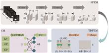
Objective It is essential to initially establish a precise recognition model to achieve accurate control for a penetration state in laser welding. Although the recognition method of the penetration state using visual signals is widely proposed, there are still interferences, such as plasma, vapor, and spattering, in the laser welding process. Besides, there is no significant change in adjacent penetration state. These are the problems in vision-based recognition of the laser welding penetration state. Feature engineering and deep learning seem to be the only methods to solve these problems. Although the feature engineering-based method is interpretable, it requires many subtasks to decrease overall recognition efficiency. Also, the value of data cannot be fully developed. On the other hand, the deep learning-based method realizes an end-to-end recognition from the original image to the penetration state. It improves the overall recognition efficiency and data value. The deep learning-based method becomes a major research focus because of integrating intelligent technologies into manufacturing systems. However, deep learning-based methods require a large amount of data, because fewer data result in overfitting. The boundary between adjacent penetration states is unclear, making it difficult for supervised learning methods to be applied. Inspired by the fact that skilled welders consider asymptotic information in deciding on the welding process, we propose a laser welding penetration state identification method that incorporates timing information. The timing information is expected to improve the determining factor of a deep learning method for the weld penetration state and increase the amount of data.Methods The frame of the proposed method consists of a spatial feature extraction module (SFEM) using a convolutional neural network (CNN), a time domain feature extraction module (TDFEM) using a bi-directional long short-term memory (BiLSTM) neural network, and a classification module (CM) using a SOFTMAX function. In the SFEM, we used two convolutional layers and two max-pooling layers to extract the input image sequence's spatial features. Afterward, we applied TDFEM to extract the features in the time domain from the input sequence. In the TDFEM, the feature sequence was simultaneously input into the forward LSTM and reversed the LSTM to obtain the forward and reverse outputs. Then, we summed the forward and reverse outputs of the same input as the final output of the current input. In the CM, we first input the spatiotemporal features into the fully connected network for dimensionality reduction. Subsequently, we mapped the low-dimension features to categorical probabilities using the SOFTMAX function. For data acquisition, the optimum penetration condition was obtained through a welding test. We incremented the laser power corresponding to the optimum penetration state, and then decremented it to obtain excessive penetration and incomplete penetration conditions.Results and Discussions Figure 5 shows that the CNN-BiLSTM method's accuracy converges to 1 after 5000 iterations, whereas the CNN method's accuracy only converges to approximately 0.93. Using the CNN-BiLSTM method, the difference in accuracy on training and validation sets is insignificant, suggesting no overfitting using the proposed method (Fig. 6). The identification accuracy and overall evaluation index of the CNN-BiLSTM method reach 99.26% on the test set, much higher than the those of the conventional CNN method. Although various CNN-LSTM method indicators are about 97%, the CNN-LSTM method only considers the previous information of current input in the time domain without considering subsequent information of current input in the time domain. The proposed method takes only 9.43 ms to identify a single image in a PC (Table 2). The CNN and CNN-LSTM methods misclassify the penetration state as the true label. Moreover, Fig. 7 shows that the proposed method can suppress misclassification. In this paper, the training process's convergence tends to be consistent when the learning rate (LR) is close to 10 -3. The model does not converge when the LR is 10 -5, suggesting no overfitting. When the optimizer (OM) is set to Adagrad or Adam, the training process's convergence is similar to that of the stochastic gradient descent method applicable to this paper. The proposed method could not converge within three epochs when the Abadelta OM is used because the Adadelta easily falls into the local optimum in the middle and later training stages (Fig. 8). Table 3 shows that all accuracy metrics of CNN-BiLSTM are above 97.66% when the LR is around 10 -3 or OM is replaced, which suggests that the proposed method is robust. Conclusions In this paper, timing information was not considered in deep learning-based methods for penetration state recognition. Our proposed method, CNN-BiLSTM, can adaptively extract spatiotemporal context information, as the method demonstrated good convergences and stability. The introduction of temporal information can indirectly play the role in data augmentation, and the proposed method does not overfit. The overall recognition accuracy of the proposed method on the test set is 99.26%. As such, the proposed method meets the standard requirements of vision-based laser welding in terms of penetration condition monitoring. Furthermore, the method is robust to changes in LR and optimizer. Although the proposed method has many advantages, the following aspects still need to be focused in future research. Better classification of penetration states will be a future interest choice in terms of research objects. Also, making the network structure fit the parallel computing system will be a good future research direction. In terms of model optimization, making the timing model lightweight without reducing the accuracy will be another good option.

Chinese Journal of Lasers
Mar. 15, 2021, Vol. 48 Issue 6 0602119 (2021)
Technology and Mechanism on Warm Laser Shock Imprinting of Aluminum Foils
Haifeng Yang, Jiaxiang Man, Fei Xiong, and Mingtian Shi

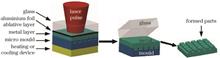
Objective Laser shock imprinting (LSI) is a manufacturing technique for material strengthening and forming using high-pressure plasma shock waves induced by laser pulses. It has been widely used in many fields. Warm laser shock peening (WLSP) combines the advantages of laser shock peening, dynamic strain aging, and dynamic precipitation and can produce microstructures with high stability. The LSI technology can produce regular large-area periodic microstructures with different shapes from hundreds of microns to nanometers on a metal foil surface. Corresponding to WLSP, the temperature-assisted LSI technology changes the forming process, forming quality, and forming mechanism of an aluminum foil. Therefore, it is important to conduct a detailed investigation on warm laser shock imprinting (WLSI) and reveal the mechanism of high strain rate plastic deformation hardening and dynamic recovery softening during multiple WLSI.Methods WLSI of an aluminum foil at different imprinting temperatures and imprinting times was conducted using the WLSI experimental devices. The imprinting temperature was controlled using an electric heating plate. We tested the forming height, surface quality, surface hardness, and microstructure of the aluminum foil using an optical profilometer, scanning electron microscope, nano-indenter, and transmission electron microscope, respectively. The ABAQUS/Explicit module was used to analyze the transient mechanical effect of the aluminum foil during the WLSI process, in which the residual stress and deformation speed of the forming parts were also analyzed.Results and Discussions For WLSI at different temperatures, when the imprinting temperature was 25 ℃, the forming height was about 8.2 μm. When the imprinting temperatures were 150 ℃ and 225 ℃, the forming height was increased to 9.3 μm, and the microstructure on the aluminum foil surface had a good forming quality. When the imprinting temperature was 300 ℃, the forming height was dropped to about 8.35 μm, and the formed part surface had a poor oxidation phenomenon (Fig. 3). The simulation results by the ABAQUS/Explicit module showed that the maximum deformation speed of the aluminum foil at 300 ℃ was about 41.8 m/s, 10.6% higher than that at 25 ℃ (37.8 m/s). Furthermore, the WLSI introduced high residual stress at the top of the microstructure. With the increase of imprinting temperature, the area of the high residual stress was increased, the maximum residual stress was decreased, and the difference between the maximum and the minimum internal stresses was decreased gradually (Fig. 5). In the WLSI at different imprinting times, compared with the forming height after single imprinting (3.8 μm), those after two (5.8 μm) and three (7.4 μm) successive imprintings were increased by 52.6% and 94.7%, respectively (Fig. 6). It should be noted that slip and twinning are the main deformation mechanisms of materials. Aluminum is a high-fault-energy metal with a small expansion dislocation width but does not easily form twin. In this study, the laser-induced shock pressure was 3.8 GPa, and the strain rate was greater than 10 4s -1 during the WLSI shock hardening and softening process. The WLSI process triggered dislocation slip in different slip planes and formed dense dislocation. The grains’ dislocation entanglement and chaotic dislocation entanglement separated the high- and low-density dislocations to form cellular substructure and sub-grains. The high-density dislocation, small cellular substructure, and sub-grains made the strength and hardness of the aluminum foil increased, which led to the second and third WLSI deformation increments. We divided the softening process at multiple WLSI into two processes, namely, dynamic recovery and dynamic recrystallization, based on the deformation conditions. Furthermore, we compared the refinement methods for high- and low-fault-energy materials with that for the medium-fault-energy materials. Our results show that the refinement methods for high- and low-fault-energy materials are more simple than that for the medium-fault-energy materials. Owing to the high-fault-energy material of the aluminum foil, dislocation slip and dynamic recrystallization result in grain refinement. However, owing to the low temperature, short deformation time, small deformation degree, and high-fault-energy, only dynamic recovery occurred in our experiment. Moreover, no dynamic recrystallization and grain refinement occurred, and a large number of cellular substructures and high-density dislocation were retained in the grains (Fig. 9). Therefore, compared with dynamic recovery softening, shock hardening plays a dominant role in multiple WLSI. Conclusions This study demonstrates that an increase in imprinting temperature reduces the flow stress of aluminum foil and makes its formation easy. WLSI leads to a high forming height and good surface quality at 150 ℃ when the imprinting temperature is 300 ℃. Furthermore, the springback and shrinkage of the aluminum foil lead to a small forming height, whereas the oxidation leads to bad surface quality. With the increase of imprinting times, the forming height of the aluminum foil gradually increases, whereas that of each imprinting decreases. After three imprinting times at 200 ℃, the forming part surfaces maintain good oxidation state and surface quality. Multiple WLSI can enhance the deformation resistance of the formed parts and strengthen the mechanical properties of the aluminum foil. Thus, the foil is subjected to the dual effects of shock hardening and recovery softening. The shock hardening plays an important role in the experiment, which ultimately leads to the successive increment of the hardness and decrement of the forming height of the aluminum foil.

Chinese Journal of Lasers
Mar. 04, 2021, Vol. 48 Issue 6 0602118 (2021)
Effect of Heat Treatment on Microstructure and Mechanical Properties of Selective-Laser-Melted TC11 Titanium Alloys
Enhui Dou, Meili Xiao, Linda Ke, Lei Du, and Caifang Lai

Objective Selective laser melting (SLM), because of its capacity to fabricate complex precision parts with high forming accuracy, has been hailed as one of the most promising manufacturing technologies for rapid prototyping. However, the mechanical properties of metal materials formed by SLM have the characteristics of anisotropy, high strength, and low plasticity. Therefore, heat treatment is always needed to control the microstructure to meet application requirements. Annealing treatment is typically adopted to improve the mechanical properties of selective-laser-melted titanium alloys. Therefore, study of the effect of annealing temperature and holding time on the microstructure, mechanical properties, and fracture mechanism of TC11 titanium alloys formed by SLM is of great significance.Methods The resulting microstructure, mechanical properties, and fracture morphology of selective-laser-melted TC11 titanium alloys under different heating temperature and holding time were studied, and the fracture mechanism under different conditions was explored. Firstly, compact TC11 titanium alloys were obtained by SLM. Secondly, different annealing heat treatments were performed on the samples. Thirdly, the phase composition of the different samples was analyzed by X-ray diffraction, and the microstructure morphology was observed by optical microscopy (OM) and scanning electron microscopy (SEM). Finally, the change in the micro-hardness of different samples was tested using a micro-hardness tester, the tensile properties at room temperature were tested, and the fracture morphology was observed by SEM.Results and Discussions The as-deposited TC11 titanium alloys are composed of hexagonal close-packed Ti (HCP/Ti), with lattice parameters a and c of 0.2934 nm and 0.46757 nm, respectively. The annealed samples consisted of HCP/Ti and body center cubic Ti (BCC/Ti), where a and c for HCP/Ti are 0.29172 nm and 0.46817 nm, respectively (Fig.3). Based on the observation of microstructure morphology by OM and SEM, it is deduced that the selective-laser-melted TC11 titanium alloys consisted of columnar grains, within which acicular α' martensite was present (Fig.4). After annealing at 850 ℃ for 4 h, fine α+β mixed structures were formed in the alloys, this was the result of the nucleation and growth of α' martensite. Due to the sufficient atomic diffusion leading to coarsening α lamellae, basket-weave structures were formed in the samples annealed at 950 ℃ for 4 h. Moreover, α clusters with the same orientation and continuous grain boundary α phase (GB α) were also observed in the grains and at the grain boundaries, respectively (Fig.5). When annealing temperature remained at 950 ℃ with holding time of 1 h or 2 h, basket-weave structures were also formed in the samples, but the width of α lamellae was about one-half and one-quarter of that in the samples annealed at 950 ℃ for 4 h, respectively. In addition, GB α phase began to transform into a discontinuous distribution (Fig.6). According to the results of the hardness test, the average micro-hardness of the as-deposited samples is about 402 HV0.5, whereas the hardness of the samples annealed at 950 ℃ for 4 h is only about 85% that of the as-deposited samples. Moreover, the micro-hardness of the samples annealed at the same temperature for 2 h and 1 h is about 381 HV0.5 and 393 HV0.5, respectively. The increase in micro-hardness with the decrease in holding time could be due to the effect of fine-grained strengthening (Fig.7). The tensile strength and percentage elongation after fracture is 1557 MPa and 2.5%, respectively, because acicular martensite is characterized by high strength and poor plasticity. However, after the samples were annealed at 850 ℃ and 950 ℃ for 4 h, the tensile strength is 72% and 64% of that of the as-deposited samples, respectively. In this case, the percentage elongation after fracture is 4.5 times and 5.7 times that of the as-deposited samples, respectively. When the samples were annealed at 950 ℃, their tensile strength increased from 996 to 1051 MPa, and the percentage elongation after fracture increased from 14.3% to 19.8% (Fig.8, Table 3). This is because the fine basket-weave structures have the effect of fine grain strengthening, and GB α has an effect on the percentage elongation after fracture. Based on fracture analysis, no obvious plastic deformation was observed in the macroscopic fracture of the as-deposited samples, and the fracture exhibited granular grain surfaces with different orientations. The microscopic fracture showed the characteristics of intergranular dimples. The above analysis indicates that the as-deposited sample underwent intergranular fracture when it was stretched at room temperature (Fig.9). However, macroscopic fractures of the annealed state had obvious plastic deformation, and the microscopic fractures showed the characteristics of dimples with larger size, indicating that ductile fracture occurred in the annealed state (Fig.10).Conclusions The effect of annealing temperature and holding time on the microstructures, mechanical properties, and fracture mechanism of selective-laser-melted TC11 titanium alloys is investigated, and the following conclusions can be drawn: The microstructures of the alloys are composed of acicular martensite within columnar grains parallel to the building direction. After annealing at 850 ℃ and 950 ℃ for 4 h, the microstructures of the alloys are fine α+β mixed and α+β basket-weave structures, respectively. As a result of decomposition of the acicular martensite, the alloys are softened, and the softening effect is more obvious with the increase in annealing time or temperature. Furthermore, the fracture mechanism changes from being intergranular to ductile, which is consistent with the regular variation of the percentage elongation after fracture. When the alloys are annealed at 950 ℃, with shorter holding time, finer lamellar α can be obtained. Continuous GB α transforms into a discontinuous distribution, finally resulting in the simultaneous increase in tensile strength and elongation after fracture. Selective-laser-melted TC11 titanium alloys with better strength and plasticity can be obtained through annealing at 950 ℃ for 1 h, with a tensile strength and percentage elongation of 1051 MPa and 19.8%, respectively, after fracture.

Chinese Journal of Lasers
Mar. 03, 2021, Vol. 48 Issue 6 0602117 (2021)
Damage Law and Mechanism of Bronze-Based Diamond Grinding Wheel Sharpening with Picosecond Green Laser
Yuanhang Zhou, Jian Zhang, Aixin Feng, Dazhi Shang, Yun Chen, Jie Tang, and Haihua Yang

Objective Bronze-based diamond grinding wheels have been widely used, and their applications have increased sharply. However, they are difficult to dress after being blunt. Traditional dressing methods, such as mechanical and electrical dressing, have the disadvantages of large loss of dressing tools, low dressing efficiency, and serious environmental pollution. The laser dressing method has significant advantages such as high efficiency, environmental protection, controllability, and wide applicability. However, if using traditional long-wavelength continuous, millisecond, or nanosecond infrared lasers, their melting/vaporization ablation mechanism can easily cause carbonization damage of the diamond abrasive grains on the surface of the grinding wheel. The short-wavelength picosecond laser has the technical advantage of “electronic state” cold processing, which can simultaneously ensure the sharpening effect and inhibit the carbonization damage of diamond abrasive grains due to high temperatures. It has significant technical advantages when dressing the grinding wheel. In this paper, the picosecond green laser was used to radially sharpen the bronze-based diamond grinding wheel. The protocols of using a picosecond green laser to sharpen the bronze-based diamond grinding wheel were explored. Moreover, selectively and quantitatively removing of the bronze matrix at the grinding wheel was achieved.Methods Firstly, a 10 ps green laser was focused on the bronze/diamond surface, and the damage thresholds were calibrated by the S-on-1 damage measurement method. This method allowed to determine the suitable working conditions for picosecond green laser to sharpen the bronze/diamond grinding wheels. Secondly, a picosecond green laser was used to sharpen the surface of the bronze/diamond grinding wheel. Thirdly, the surface morphology and roughness were characterized using the laser confocal microscope. Finally, the effects of laser peak power density, repetition frequency, and scanning times on the sharpening effect were studied.Results and Discussions 1) The damage thresholds of the bronze matrix and the diamond abrasive grains differed in two orders of magnitude and amounted to 1.23×10 9 W/cm 2 and 3.71×10 11 W/cm 2, respectively (Fig. 4). The difference in damage threshold was conducive to the selective micro-removal of the bronze matrix and the selection of the sharpening process parameters. 2) The picosecond laser damage characteristics of bronze diamond grinding wheels were studied. Next, these characteristics are compared with the traditional approach using a continuous or short-pulse laser. Picosecond laser has greatly reduced the carbonization of diamond abrasive grains. If the appropriate peak power density was selected, the diamond abrasive grains were not easy to be carbonized even at high repetition frequency, there was no obvious heat trace. 3) The laser power density played a major role in the sharpening effect (Fig. 7). When the laser power was constant, adjusting the number of scans quantitatively removed the bronze matrix at the surface of the grinding wheel (Fig. 9). When the power density was constant, a proportional increase in both the laser power and repetition frequency achieved a good sharpening effect. However, the gradual accumulation of heat has increased the chances of carbonization (Fig. 8). Conclusions In this study, the damage rules and mechanisms of bronze-based diamond grinding wheels sharpening with picosecond laser were studied. Moreover, the damage threshold of the picosecond laser ablation of the bronze matrix/diamond was quantified, and the laws of different process parameters acting at the surface of the grinding wheel were analyzed. The removal mechanism of the picosecond green laser on the bronze matrix is mainly vaporization. It allowed avoiding the carbonization of diamond abrasive grains. Even at high repetition frequencies, there was no obvious heat accumulation. The study shows that the damage threshold of the bronze matrix and diamond abrasive grains are different in two orders of magnitude. The bronze matrix can be selectively removed by adjusting the peak power density and quantitatively removed by adjusting the number of scans. Moreover, the picosecond green laser is capable of ensuring the integrity of the diamond abrasive grains by selectively and quantitatively removing the bronze matrix.

Chinese Journal of Lasers
Mar. 08, 2021, Vol. 48 Issue 6 0602116 (2021)
Microstructure and Properties of High Speed Laser Cladding Stainless Steel Coating on Sucker Rod Coupling Surfaces
Yanfang Wang, Xiaoyu Zhao, Wenjun Lu, Chenyan Pan, Yudong Si, Zhiqiang Shi, Yanling He, and Bin Han

Objective Sucker rod coupling failure is a major problem in sucker rod pumping systems, which are frequently used in oil fields worldwide. Surface modification of sucker rod couplings is an economical method to address this problem. High speed laser cladding (HSLC), which is proposed on the basis of laser cladding technology, is a novel additive manufacturing technology for surface modification. A HSLC modifies the relative positions of laser beam, spray powder, and molten pools, thus powder particles can be heated to their melting point before being guided into the molten pool. Due to limited transmitted laser energy, a micro-molten pool can form on the substrate such that a coating with low dilution ratio and metallurgical bonding is produced. The HSLC in this study has a higher cladding efficiency (500 cm 2/min) and a suitable coating thickness (25 μm to 500 μm), which overcomes the efficiency obstacle of conventional laser cladding technology. It provides a highly efficient and low-cost production method for the fabrication of thin coatings on sucker rod couplings to improve their surface properties (such as hardness, wear resistance and corrosion resistance). In this paper, martensitic stainless-steel coating is prepared on the surface of a 35CrMo sucker rod coupling by HSLC, followed by laser remelting (LRM), to explore a new way to improve wear resistance and corrosion resistance of the sucker rod couplings. Methods Martensitic stainless-steel powder, with particle diameters ranging from 15--53 μm, is selected as the cladding material. Coatings are prepared by a ZKZM-4000 HSLC system. The laser cladding parameters are: 3500 W laser power, 7 m/min scanning speed, and 60% overlap ratio. The remelting parameters are: 3500 W laser power, 15 m/min remelting speed, and 50% overlap ratio. After the laser cladding and remelting processes, specimens are cut from the substrate, then mounted, ground, and polished for microstructure observation and property testing. The microstructure of the HSLC and LRM coatings are characterized by optical microscopy. The phases of the coatings are determined by X-ray diffraction (XRD). The hardness distribution of the coatings is studied using a hardness meter. The tribological properties are tested using a MFT-EC4000 friction and wear tester. Potentiodynamic polarization and electrochemical impedance spectroscopy of the coatings and substrate, in a 3.5% NaCl solution, are also measured using a Perkin-Elmer M398 electrochemical workstation.Results and Discussions The HSLC coating is fully dense, smooth, and without any noticeable stomata, inclusions, or cracks. The thickness of the coating is approximately 512 μm, while the heat affected zone is only about 85 μm. The surface roughness of HSLC is 15.7 μm. LRM can reduce the surface roughness to 5.4 μm because of the remelting of surface powders. The HSLC coating is composed of single martensitic structure. The phase composition does not change after LRM processing. However, the width of the diffraction peak varied due to the changes in grain size. The HSLC coating shows a special multi-layer lapped character. The coatings form a metallurgical bond with the substrate due to the maximum temperature gradient and slow growth rate; planar crystals appear at the combined zone. The middle cladding layer contains dendrites with a typical epitaxial growth tendency along the temperature gradient. Near the surface of the coatings, the dendrites become fine equiaxed grains without an obvious preferential growth direction. LRM can improve the multi-layer lapped character and refine the dendrites. Some lump-structure dendrites are formed in the surface because of the high cooling rate.The average hardness of the HSLC and LRM coatings is 470 HV and 494 HV, respectively, which is about 2.2 times that of the substrate. The average friction coefficient of the substrate, HSLC coating, and LRM coating are 0.22, 0.24, and 0.33, respectively. However, the wear loss of the LRM coating, HSLC coating, and substrate increases in that order. The wear loss of the samples does not show an obvious relationship with their friction coefficients, which suggests contributions from various wear mechanisms. The worn surface of substrate shows various ploughed groves parallel to the sliding direction, which is a typical feature corresponding to the abrasive wear mechanism. However, wear pits can be found on the worn surface of the HSLC and LRM coatings. The worn scar of the HSLC coating or LRM coating is shallower and wider than those of the substrate, which contributes to the adhesion wear mechanism.Both HSLC and LRM coatings show excellent corrosion resistance with passive regions. The self-corrosion potential (Ecorr) for the LRM coating is highest, at approximately -0.370 V, and the self-corrosion current density (Icorr) is lowest, at 2.599 μA/cm2. The HSLC coating and substrate have Ecorr and Icorr values of -0.5261 V and 6.195 μA/cm2 and -0.7469 V and 9.259 μA/cm2, respectively. Nyquist plots for the substrate, HSLC coating, and LRM coating are all unfinished capacitance arcs with different radii and impedances. The analog circuit could be expressed by R(QR). The corrosion resistance of the coatings is also evaluated by the model value of impedance (|Z|) and the phase value; a higher value of impedance and phase angle suggest a more stable passive film. The maximal value of capacitive arc radius, impedance, and the phase angle are all higher for the LRM coating. HSLC improved the wear resistance and corrosion resistance of the substrate and LRM further improved the performance of the HSLC coating.Conclusions A novel HSLC and LRM technique successfully developed a pore and crack-free martensitic coating on a sucker rod coupling surface. The HSLC coating shows a gradient structure, consisting of planar crystal, columnar dendrites, and equiaxed crystals from bonding zone to surface. The coating exhibits good wear resistance and corrosion resistance. LRM leads to refined dendrites and a uniform distribution of composition, which is helpful for enhancement of surface properties. HSLC and LRM are potential methods for improving the wear resistance and corrosion resistance of sucker rod couplings for industrial applications.

Chinese Journal of Lasers
Mar. 08, 2021, Vol. 48 Issue 6 0602114 (2021)
Mechanical Properties of Laser Hybrid Welded Joint of 1000 MPa Ultrahigh-Strength Steel
Yanlong Ma, Hui Chen, Xu Zhao, Chengzhu Zhang, and Zhiyong Zhu

Objective Currently, the development of lightweight materials has become the primary objective of manufacturing, and the application of high-strength steel has emerged. Compared with traditional lightweight materials such as aluminum and magnesium alloys, 1000 MPa ultrahigh-strength steel exhibits good strength and toughness, high safety performance, and low application costs. It also exhibits good economic benefits. However, the application of high-strength steel requires reliable welding joints. Recently, the welding joints obtained via traditional welding methods are softened, the heat-affected zone is embrittled, the impact toughness of welding joints is low, the joint strength is lower than that of the base metal, the welding deformation is large, and the welding efficiency is low. As a new type of heat source welding method, laser-arc hybrid welding can effectively restrain the softening of the heat-affected zone, reduce damage to the base material, and exhibits a high welding efficiency and small deformation, etc. Furthermore, the performance of welding joints of 1000-MPa-grade tempered ultrahigh-strength steel increasingly deteriorates with the increase of strength, limiting the popularization and application of this type of high-strength steel. Therefore, it is considerably important to select appropriate filling materials and adopt laser-arc hybrid welding for studying the performance of welding joints of this type of high-strength steel.Methods Equal-strength matching welding wire MG90-G and low-strength matching welding wire ER80YM were selected to perform laser-arc hybrid single-pass welding on the 1000-MPa-grade quenched and tempered ultrahigh-strength steel BS960E to well solve the deterioration of the welded joint performance of this type of high-strength steel. The welding equipment is manufactured using a 10 kW fiber laser (TRUMPF LASER TruDisk 10002) and a welding machine. The laser-guided hybrid welding method is adopted. In addition, the groove form is type I, and the butt gap is 1 mm. The welding process is optimized through the single factor variable method, and the welding quality is evaluated via non-destructive flaw detection. The heat input changes are collected based on the thermal cycle. The tensile strength, hardness, and low-temperature impact toughness of the welding joints for two types of welding materials were tested, and the fracture was analyzed via microscope and scanning.Results and Discussions The mechanical properties of the BS960E laser-arc hybrid welded joints were analyzed when using different welding speeds and welding materials, and the following results were obtained. 1) Welding quality: The weld formation was good when the welding speeds were 1.32 m/min and 0.72 m/min. With the increase of welding speed, the porosity of welding seam decreased significantly. Thus, a stable molten pool at high welding speed can inhibit the generation of porosity. At a high speed, the fusion ratio of welding joints increases, the beneficial elements of welding wire transition to welding seam are reduced, and the impact property of welding seam deteriorates. 2) Hardness and microstructure: Under the condition of high-speed welding, the hardness of welds increases by 9.7% compared with that observed under low welding speeds. Laser-arc hybrid welding can effectively improve and restrain the softening of welding joints, and the hardness of the softening zone is reduced by 8.8% compared with that of the base material. The microstructure of the weld with a welding speed of 1.32 m/min includes bainite and M-A component, and the microstructure in the heat-affected zone is lath martensite. 3) Tensile properties: The tensile strengths of 90 wire and 80 wire welded joints are 1129, 1117, 1145, and 1084 MPa, respectively. The tensile strength is equivalent to that of the base metal, and the elongations observed in the aforementioned cases are 93%, 98%, 104%, and 102% of the base metal, respectively. Thus, low-strength matching has better ductility. 4) Impact performance and fracture: The impact performances of the two welds at low welding speeds increased by 28.5% and 15.7%, respectively, compared with those observed at high welding speeds. The impact fracture of the welding seam of the two types of welding wires exhibits the characteristics of ductile fracture, and the impact fracture of the heat-affected zone is mainly manifested as a brittle fracture. With the decrease of welding speed, the brittleness of the MG90-G welding joint in the heat-affected zone increases, but the impact performance deteriorates less obviously because of the small difference in the welding input energy. However, the impact toughness of the ER80YM wire welded joint in the heat-affected zone increases with the decrease of welding speed.Conclusions Research results show that laser-arc hybrid welding can effectively improve the softening of joints and reduce the width of heat-affected zone of joints; therefore, the tensile fracture can be observed in the base metal. Under the action of the laser heat source, laser-arc hybrid welding can effectively improve defects such as undercuts caused by traditional welding. Further, under the conditions of fast cooling and heating, the weld porosity can be effectively reduced by increasing the welding speed. From the matching analysis of welding materials, the laser-arc hybrid welded joint with low-strength matching wires exhibits better ductility than that obtained in case of equal-strength matching wires. Further, the tensile strength is equivalent to that of the base metal. Under the same welding process parameters, the impact performance of different welding wire welded joints is small, which can be attributed to the unevenness of the weld metal composition and the influence of fusion ratio. Currently, the impact performance of the welded joints of this type of high-strength steel is a weak link, which must be further improved. Therefore, under the condition of laser-arc hybrid welding, the selection of appropriate heat input and low-strength matching welding wires can effectively improve the low-temperature impact performance of welding joints.

Chinese Journal of Lasers
Mar. 18, 2021, Vol. 48 Issue 6 0602113 (2021)
Parameter Optimization of High Deposition Rate Laser Cladding Based on the Response Surface Method and Genetic Neural Network Model
Yifan Pang, Geyan Fu, Mingyu Wang, Yanqi Gong, Siqi Yu, Jiachao Xu, and Fan Liu

Objective As a new advanced manufacturing technology, laser cladding rapid prototyping has been widely used to laser forming without any need for a mold or die. However, the traditional laser cladding usually adopts the low-power forming below 2000 W, which is inherent with problems such as low deposition efficiency, long-forming time, and insufficient material use. In contrast, the high-power hollow ring laser cladding can effectively improve the forming efficiency by optimizing the experimental process parameters using model analysis. In recent years, neural networks have been gradually applied to optimize multi-parameter objective in laser cladding, laser welding, and laser communication. The neural network prediction model is capable of fitting and modeling nonlinear data through iterative learning without the need to specify the function form in advance, demonstrating excellent ability to deal with multivariate nonlinear problems. However, the single neural network model may suffer from problems like slow and easy to fall into local extremum training speed. In this study, not only a neural network model optimized by a genetic algorithm is proposed to predict and optimize the laser cladding deposition efficiency, but also the parallel random search is employed to effectively solve the aforementioned two problems of the training process in the model. We expect that our research can contribute to improving deposition efficiency and shortening forming time in high-power laser cladding forming.Methods The experimental equipment adopts the hollow ring internal light powder feeding cladding system, which mainly consists of a 6 kW Raycus laser, a 6-axis KUKA robot, and a hollow ring internal light powder feeding nozzle. The cladding material is Fe314 powder and the experimental substrate is 304 stainless steel. The effects of the laser power, scanning velocity, powder feeding velocity, and defocusing on the deposition rate of the cladding layer were studied systematically by an orthogonal experiment. The tissue differences of the samples under high and low deposition rates were consistently observed by scanning electron microscope. The Box-Behnken(BBD) experiment was then designed by the response surface method to study the influence of several interaction factors on the deposition rate. Meanwhile, the multiple regression model was also established to predict and optimize the deposition rate. Additionally, a series of randomized trials were conducted as a supplement. Both the results of the BBD experiment and the samples of the randomized trial were taken as the training data of the genetic neural network, and eventually, the genetic neural network model was trained to predict and optimize the deposition rate. By comparing the modeling ability, generalization ability, and optimization ability of the two models, the most suitable model was selected as the estimator for the following experiments to accomplish closed-loop control of the deposition rate.Results and Discussions The range analysis method was adopted to analyze the orthogonal experimental results. It is indicated that powder feeding rate has the greatest influence on the cladding deposition rate followed by laser power and scanning speed, and the defocusing amount on the cladding deposition rate was of the least influence (Table 3). When it comes to the reciprocal influence of various factors on the deposition rate, the response surface methodology (RSM) model shows that the interaction effect between laser power and powder feeding rate is the most significant. This is probably because the laser energy density improves as the laser power enhances, resulting in the enlargement of the high-temperature range in the molten pool. Within a certain power range, the deposition rate increases significantly by increasing the molten powder in the molten pool [Fig. 5(a)]. The second interaction effect is between scanning speed and powder feeding rate [Fig. 5(b)], and the interaction effect between defocusing amount and laser power is the least significant [Fig. 5(c)]. Simultaneously, the comparison of the predicted experimental values of genetic algorithms-back propagation (GA-BP) and RSM models after training shows that both models have good fitting accuracy, but the value of R2 in GA-BP is closer to 1 (Fig. 8). By comparing the generalization ability of GA-BP and RSM models, the absolute average deviation(AAD) values of RSM and GA-BP models were 8.762% and 4.938%, respectively (Fig. 9). The maximum deposition rate obtained by the optimized GA-BP model was 61.74 g/min, which was higher than the value of 53.55 g/min obtained by the response surface method (Table 7). The above studies show that the prediction, generalization, and optimization capabilities of the genetic neural network model are superior to those of the response surface model, and the neural network model optimized by the genetic algorithm can provide a more effective prediction method for the achievement of laser cladding forming with high deposition rate. Conclusions In this study, considering the orthogonal experiment in the hollow ring internal light powder feeding cladding system, the BBD experiment designed by response surface method was adopted and an RSM model using deposition rate as the response target was established. Subsequently, the influence of laser power, powder feeding speed, scanning rate, and defocusing amount on the deposition rate of high-power laser cladding was systematically investigated, individually or interactively. Based on the results of the BBD experiment and the samples of the randomized trial, a GA-BP model was set up. Comparing the performance of the two models by analyzing the modeling and generalization abilities, the technological parameters of laser cladding with high deposition rate were optimized. In conclusion, the performance of the GA-BP model is slightly better than that of the RSM model as the root mean square error and the average absolute deviation of the GA-BP model are smaller than those of the RSM model, and the decision coefficient values obtained in the RSM model and GA-BP model are 0.9479 and 0.9726, respectively. The prediction abilities of GA-BP and RSM models are fairly close, but under the condition of high deposition rate, the optimal deposition rate in the GA-BP model is 61.74 g/min, which is higher than the value of 53.55 g/min optimized by the RSM model. Briefly, the GA-BP model can be considered an effective method to optimize the high deposition rate of cladding. Because of the high reliability, the model can find the optimal deposition rate within a specific process range, which can be used as an estimator for operating closed-loop control over the following forming system to obtain high-efficiency and high deposition rate in the later cladding.

Chinese Journal of Lasers
Mar. 15, 2021, Vol. 48 Issue 6 0602112 (2021)
Effects of Oscillation Parameters on Weld Formation and Porosity of Titanium Alloy Narrow-Gap Laser Wire Filling Welding
Kaixin Xu, Zhen Lei, Ruisheng Huang, Naiwen Fang, and Hao Cao

Objective Titanium and its alloys are indispensable and satisfactory owing to its superior physical and chemical properties: high specific strength and modulus, excellent thermal strength, and corrosion resistance. Against the background of the industrial rapid development, the aerospace manufacturing industry has put forward requirements for light-weight and large-scale aircraft, which intensely increased the use of titanium alloys. There are considerable studies based on laser welding of titanium alloy sheets, and significant effort has been made. However, a few studies have been conducted on the joining of thick titanium alloy plates, leaving many technical problems unsolved. For the welding of a thick titanium alloy plate, the arc welding process is a low-cost method, with poor weld beam formation, high residual stress, and wide heat-affected zone. Electron beam welding (EBW) is one of the high energy density welding processes. The challenges of EBW is obvious, and its application is severely limited by the vacuum condition. Several studies stated that narrow-gap laser filling welding is an optimal choice for the joining of thick plates, compared with other welding processes. In this paper, we investigate and analyze the effects of laser beam swing parameters on the formation and porosity of TC4(Ti-6Al-4V) titanium alloy narrow-gap laser filling welding. We obtain that it could eliminate the lack of fusion and reduce porosity with matched laser beam oscillation mode, amplifier, and frequency. It could provide basic data and theoretical supports for thick titanium alloy welding.Methods Titanium alloy plate (TC4(Ti-6Al-4V)) and wire (TC3(Ti-5Al-4V)) are used in this study. First, 2 mm-wide-gap TC4(Ti-6Al-4V) is filled with TC3 wire by laser swing welding, which takes different oscillation modes: amplitude and frequency. A well-formed surface and cross-section with low porosity are selected as suitable oscillation parameters. Next, 20 mm-thick TC4(Ti-6Al-4V) is welded by selected parameters. Apart from surface formation and cross-section, the weld joint has been analyzed by X-ray pore detection and tested tensile strength. Then, the tensile fracture is analyzed by a scanning electron microscope.Results and Discussions The weld surface formation cloud improves a lot despite the laser beam oscillation mode considered. The fusion depth gets smaller, and the fusion width gets bigger in the cross-section (Table 2), which could reduce the lack of fusion. When the oscillation amplitude is between 1.5 mm and 2 mm, and the frequency is between 100 Hz and 200 Hz with circular oscillation, the surface of the weld becomes continuously smooth, and the cross-section turns wider and shallower (Table 3 and Table 4). A bigger form factor of weld applies to narrow-gap welding to reduce lack of fusion matched oscillation parameters could be selected with form factor and porosity (Fig. 4). When the oscillation frequency is between 100 Hz and 200 Hz with 2 mm amplitude and circular swing, no pore was detected on the X-ray films (Fig. 5). 20-mm-thick TC4(Ti-6Al-4V) has been welded by narrow-gap laser beam swing with circular 2 mm and 100 Hz oscillation. The results showed that the weld joint gets a well-formed surface and has no pore in the X-ray film. In the tensile strength tests, the weld joint maximal tensile strength reaches 930 MPa, which is the same as base metal and the tensile samples are ductile fracture (Fig. 10).Conclusions In this study, narrow-gap TC4(Ti-6Al-4V) plates are welded by swing laser wire filling welding. Compared with non-oscillating laser welding, the surface forming can be improved after the beam swings, and the continuous smooth weld can be obtained. Under the circular oscillation, when the oscillation amplitude is between 1.5 mm and 2 mm, and the frequency is between 20 Hz and 100 Hz, the well-formed weld can be obtained. When the oscillation mode is linear and circular, the porosity is relatively small, while when the oscillation mode is non-oscillating and infinite oscillation, the porosity is relatively large. When the oscillation amplitude is 2 mm, the porosity is small, and no obvious pore is found from the X-ray films when the oscillation frequency is between 100 Hz and 200 Hz. Owing to comprehensive consideration of weld formation and porosity, with the circular oscillation 2 mm amplitude and 100 Hz frequency of the oscillation parameters, we have completed the 20 mm-thick TC4(Ti-6Al-4V) narrow-gap laser wire filling welding with well forming joint surface, and no obvious pore was detected from X-ray detection. The maximum tensile strength of the 20 mm-thick weld joint reaches 930 MPa, which is the same as base metal, and the fracture mode is a ductile fracture with a dimple fracture surface under the scanning electron microscope. We obtain matched oscillation parameters. The data has been validated with well formation and property from the test of the 20 mm-thick weld joint, which plays a significant role in thick titanium alloy welding.

Chinese Journal of Lasers
Mar. 15, 2021, Vol. 48 Issue 6 0602111 (2021)
Effect of Substrate Orientation on Formation of Heterocrystals in Laser Cladding Zone
Peng Rong, and Jiachen Guo

Objective Renovating surface defects of Ni-based single crystal superalloy blades is the key to prolong their manufacturing life, and repair mechanism is also a hot research topic in material physics and chemistry. In this study, laser melting method combined with theoretical model calculation is used, and the self-developed DD series Ni-based superalloys in China is taken as the research object. On the basis of previous studies, the substrate orientation has rotated 45°around the direction of [010] during laser melting of single crystal alloys, then rotate different angles ξ along the direction of [001], the distribution and variation of different crystal orientation regions with the increase of ξ are studied. It is found that with the increase of ξ, the distribution of single crystal domain increases on the side of molten pool. Substrate orientation 112/[201ˉ] with single crystal region on one side of molten pool is obtained. Repairing operation on its substrate, because of the disappearance of [010] domain in the molten pool of epitaxial growth repair zone, the grain boundary [001]/[010] also disappears, the ability of stray grain formation is greatly reduced. The substrate orientation suitable for laser cladding repair is obtained, and the mechanism of the effect of changing substrate orientation on the formation ability of stray grain in the epitaxial growth structure is demonstrated.Methods In our previous research, the mechanism of substrate orientation for the formation of equiaxed crystals has been elaborated in detail. It is defined that when the laser scans along the [100] direction on the crystal plane, that is, the substrate orientation relationship is the initial substrate orientation. When the initial matrix is rotated 45° around the crystal direction (i.e., the y-axis), the growth of heterocrysts can be effectively suppressed. On this basis, this study continues to take the crystal direction as the rotation axis. Through the second rotation of different ξ and laser melting technology, the mechanism of inhibiting the growth of heterocrystals is revealed, and the optimal substrate orientation is obtained to effectively control the single crystal nature of the repaired area.Results and Discussions According to the experimental results, for the initial substrate crystal orientation (001)/[100], the value of the single-layer repair height is limited by the position of the [001]/[100] crystal zone boundary in the laser cladding epitaxial growth structure, and the position of the [001]/[100] crystal zone boundary in the weld pool is related to the initial substrate crystal orientation. For the matrix (101)/[101]ˉ crystal orientation rotated 45° around the y-axis, as shown in Fig. 2 (a) and Fig. 2 (b). In this case, because there is no crystal zone boundary in the epitaxial growth structure by laser cladding, the height can be effectively raised in the single-layer repair. However, the monocrystal property of the repaired structure is affected by the existence of the sum zone on the left and right sides. However, when the substrate with ξ=45° is used (as shown in Fig. 10), due to the disappearance of the [010] crystal zone in the weld pool of the epitaxial growth repair structure, the intersection line of the [001]/[010] crystal zone on one side of the corresponding molten pool is generated, and all the crystal regions are [001] crystal regions on one side of the molten pool, so the substrate orientation with only a single crystal zone can be obtained. Based on the above matrix orientation combined with multi-channel and multi-layer laser cladding experiment, the single crystal structure of laser cladding repair can be obtained completely, which plays a great role in improving the single crystal property of laser cladding epitaxial growth structure.Conclusions In this paper, we propose a laser cladding repair method for the secondary rotating matrix, and obtain the substrate orientation suitable for the growth of single dendrite direction. The specific conclusions are as follows:1. In the experiment of laser cladding epitaxial growth and repair, the choice of the initial substrate orientation can affect the ability of heterocrystal formation in cladding epitaxial growth structure under the condition of other repair parameters such as laser parameters, scanning speed and so on.2. When the initial crystal direction rotates 45° around the y-axis, the crystal direction is rotated by the rotation axis (secondary rotation). When ξ=45°, the laser cladding repair process is carried out along the crystal direction on the surface. The single-layer repair height increases and the single-layer dendrite growth direction is ensured on one side of the weld pool, so as to ensure the monocrystalline of the laser cladding epitaxial growth structure.3. The internal mechanism of this situation is that after changing the initial crystal substrate orientation, the crystal area in the laser melting pool expands and occupies the area where the original crystal zone is located, and the boundary of the crystal zone disappears in the molten pool. Therefore, a large single crystal area can be adopted, which ensures the repair efficiency and single crystal property of the laser cladding epitaxial growth structure.

Chinese Journal of Lasers
Mar. 03, 2021, Vol. 48 Issue 6 0602110 (2021)
Plastic Gradient Coordination Behavior of Boron Steel/Q235 Steel Laser Welded Joint Under Welding with Synchronous Thermal Field
Guangtao Zhou, Huachen Li, Fang Liu, and Hepeng Cui

Objective For hot stamping high strength boron steel B1500HS and Q235 steel, dissimilar materials laser welding tailored blanks combine the excellent properties of the two materials and can meet the special performance requirements of the structure. For example, B-pillar of automobile body structure requires that the upper and lower sections of B-pillar have low strength, while the middle section has high strength. However, due to the difference in mechanical properties of the materials connected at the end of the welded joint interface, the stress singularity and other mechanical mismatching effects are caused in the interface among weld, heat-affected zone (HAZ), and base metal (BM), forming a plastic gradient. So far, there are few researches on controlling the plastic gradient in each region of the welded joint during laser welding, so it is very necessary to find a method to control the plastic gradient of the welded joint. In this paper, welding with synchronous thermal field (WSTF) method is proposed in order to regulate the cooling rate of the joint, intervene the structural transformation of each region of the welded joint, reduce the plastic gradient and coordinate the plastic of each region. A comparative investigation of 2 mm boron steel/Q235 steel laser welded joint prepared by conventional laser welding and the WSTF conditions is carried out to systematically evaluate the differences about plasticity between them, and further provide a beneficial reference for the selection of controlling the plastic gradient of dissimilar material laser welded joint in practical engineering applications.Methods Boron steel/Q235 steel laser welding tailor blanks are performed using YAG laser device. The welding conditions are conventional laser welding with 300, 450, 600 ℃ thermal fields, respectively. After that, high temperature tensile test, fracture morphology, and microstructure are observed by using electronic high temperature tensile testing machine, scanning electron microscope, and metallographic microscope, respectively. The high temperature tensile tests are conducted under 700, 750, 800, 850, 900 ℃, respectively. By comparing the above results, the plastic gradient difference of boron steel/Q235 steel welded joint under conventional laser welding and WSTF conditions is obtained.Results and Discussions By comparing the high temperature tensile test and microstructure of boron steel/Q235 steel laser welded joint under conventional laser welding with 300, 450, 600 ℃ synchronous thermal field, respectively, it can be found that: 1) elongation: compared with the conventional condition, the elongation of 300, 450, 600 ℃ increases by 19.70%、 20.69%、 21.21% respectively (Table 5). 2) fracture angle: under conventional laser welding conditions, the fracture Angle of the joint is only 115°. Under the synchronous thermal field conditions of 300, 450, 600 ℃, the fracture angle increases by 13.04%, 21.74% and 41.74%, respectively(Fig. 8). 3) plastic strain: when the thermal field temperature is 600 ℃, compared with the conventional conditions, the plastic strain in the weld increases by 31.47%, the HAZ of Q235 steel increases by 28.23% and the HAZ of boron steel increases by 28.61%(Fig. 10). The plasticity of each region is more gradual and harmonious. 4) microstructure: under conventional conditions, the majority of the weld and the HAZ of boron steel are martensite, while the content of martensite in the HAZ of Q235 steel is relatively small, and ferrite and pearlite account for the majority. Under the condition of 600 ℃ thermal field, the microstructure of the weld is mostly ferrite and pearlite, while the microstructure of the HAZ of boron steel is mostly ferrite and the difference with the ferrite microstructure of the weld is smaller. There is almost no martensite in the HAZ of Q235 steel, but all ferrite and pearlite, and the fusion line interface transition is more uniform (Fig. 13).Conclusions The results show that through synchronously applying the preset thermal field during the laser welding process and laser heat source for boron steel/Q235 steel welded tailor blanks, under the synchronous effect of thermal field and laser heat source, the WSTF method improves the microstructure transformation of weld and HAZ of boron steel and Q235 steel. The method can effectively improve the plasticity of integrated boron steel/Q235 steel welded joint, significantly reduce the plastic gradient in each region of the joint and make it to be gradual and harmonious. For integrated boron steel/Q235 steel laser welded joint, the higher the temperature of the thermal field, the higher the elongation of the integrated welded joint, and the more flat the fracture surface. For each region of boron steel/Q235 steel laser welded joint, the plasticity of the weld is obviously improved, the difference of stress-strain relationship among the weld, the HAZ and the BM is reduced, and the deformation of each region of the welded joint is more coordinated. Due to the reduction of cooling rate of weld and HAZ after welding, the temperature is higher and the retention time is longer, the formation of the brittle organization is avoided. The difference between the weld and its both sides is smaller, the transition at the interface of each region is more uniform, and the plastic gradient is greatly reduced. Therefore, the plasticity of boron steel /Q235 steel laser welded joint is higher than that of conventional laser welding under WSTF, and the plasticity is consistent and coordinated.

Chinese Journal of Lasers
Mar. 04, 2021, Vol. 48 Issue 6 0602109 (2021)
Spot Ablated by Femtosecond Laser Classification Based on Cascaded Support Vector Machine
Fubin Wang, Mengzhu Liu, and Tu Paul

Objective Femtosecond laser micromachining technology has excellent three-dimensional (3D) processing capabilities and provides significant advantages in the production of experimental materials with complex 3D structural features. However, the continuous improvement of ablation efficiency and accuracy is still an eternal topic. The femtosecond laser ablation of monocrystalline silicon is accompanied by the luminescence phenomenon derived from the plasma. During the movement of the three-degree-of-freedom motion control platform in 3D space, the plasma spot produces different forms, particularly during the reciprocating ablation process in the X direction, and two distinct spot forms appear. The trailing direction of the light spot is the upper and lower left when moving forward and backward, respectively. The optimized cascaded support vector machine (SVM) classifier is used to accurately classify and analyze the light spot and can explore the ablation efficiency and accuracy in different ablation directions.Methods First, the SVM classifier uses the feature of the spot centroid to classify the light spots at the first level. Then, we introduce the means of upper and lower peer lines and obtain two types of light spots. One type is correctly classified into the corresponding ablation direction, called the R light spot, which includes the first-level UP light spot (the trailing direction is the upper left) and first-level DN spot (the trailing direction is the lower left). The other type is incorrectly classified into the opposite ablation direction, called the E spot. Next, the first-level DN spot is superimposed, and the average value is calculated to obtain the average spot. To further obtain the standard model to maximize the similarity of each first-level DN spot, the mean spot is placed into a generative adversarial network (GAN) for training and generation. Compared with random noise, the use of average light spots can reduce the number of training and produce a final generated image more similar to the standard model. Finally, SSIM is used to calculate the similarity between the E spot and standard model, and the E spot is classified using the second-level SVM to generate the second-level UP and DN. Combining the E spot with the first-level UP and DN spots, the final classification result is achieved.Results and Discussions Using this method, the classification accuracy is 100% under the processing power of 10 mW. In the entire ablation cycle, 34 spots are produced corresponding to the two trailing directions in the two ablation directions. Under 20 mW, the classification accuracy is also 100%. Each half of the ablation cycle produces 33 light spots in the same trailing direction. The deviation is the classification result under 50 mW, and its accuracy is 98.5%. There should be 66 light spots in the same motion state every half cycle; in the second half cycle, one light spot is not correctly classified in the classification result. In the entire time series, only two spots are misclassified, which is close to 100%, and the classification effect is significantly improved. To verify the accuracy of the cascaded SVM classifier in the classification of different states of light spots generated under different ablation directions, three classification methods of histogram of oriented gradient (HOG)-SVM, local binary mode (LBP)-SVM, and Gaussian pyramid (GP)-SVM are compared. Among them, HOG is constructed by calculating and counting the histogram of the gradient direction of the local area of the image operating on the image local grid unit and maintaining good invariance of the image deformation. LBP is an operator that can effectively measure and extract local texture information of an image. It has significant advantages such as nonrotational deformation and gray invariance. GP downsamples the image to obtain partial information of the image. Compared with the traditional HOG-SVM, LBP-SVM, and GP-SVM classification methods, the classification accuracy of the cascaded SVM classifier is increased by 5 to 9 percentage points, 12 to 16 percentage points and 9.0 to 15.5 percentage points 10, 20, and 50 mW, respectively. The cascaded SVM classifier delivers nearly 100% classification accuracy for the spot when using each level of processing power, which has obvious advantages.Conclusions To classify the different forms of light spots in the femtosecond laser ablation process of single crystal silicon, an optimized cascaded SVM classifier is used. First, the first-level classification is performed based on the spot centroid feature. Then, the standard model is established by generating confrontation GAN. Next, the second-level SVM classification is performed using the structural similarity SSIM of the misclassified spot and the standard model. The classification results are remarkable. A better understanding of the movement state of the light spots can aid further exploration of the law of ablation. It has an indelible effect on the improvement of ablation efficiency and accuracy.

Chinese Journal of Lasers
Mar. 15, 2021, Vol. 48 Issue 6 0602108 (2021)
Investigation of Microstructures and Mechanical Properties of Laser-Melting-Deposited AlCoCrFeNi2.5 High Entropy Alloy
Liufei Huang, Yaoning Sun, Yaqi Ji, Changgui Wu, Guomin Le, Xue Liu, and Jinfeng Li

Objective Recently, with the development of laser technology, increasingly complex components of high entropy alloy (HEA) can be prepared using laser three-dimensional (3D) printing technology. However, HEA prepared using this method exhibit low strength and plasticity. Therefore, AlCoCrFeNi2.5 HEA with high plasticity is introduced in laser melting deposition (LMD) technology, which is a laser 3D printing technology. Herein, the microstructure and mechanical properties of AlCoCrFeNi2.5 HEA prepared using LMD are studied. We aim to fabricate HEA with excellent mechanical properties using the laser 3D forming method.Methods LMD has been developed to synthesize AlCoCrFeNi2.5 HEA. The laser process parameters are as follows: laser power, scanning speed, powder feeding speed, shielding gas flow rate, spot diameter, defocusing amount, and lifting amount are 700 W, 400 mm/min, 8 g/min, 5 L/min, 2 mm, 11 mm, and 0.25 mm, respectively. The material used for LMD is AlCoCrFeNi2.5 high entropy prealloyed powder (sphericity ≥90%), and the range of the alloy particle size measured using the laser particle size analyzer is 45--105 μm. The alloy powder is placed in a vacuum drying oven, heated to 120 ℃, and retained for 2 h. Then, it is cooled to room temperature in a vacuum environment, poured into a powder feeder, and placed in a feeding barrel for standby. Further, a 316L stainless steel plate with dimensions of 100 mm×60 mm×10 mm is selected as the base plate, and the oxide layer on the surface is removed using a grinder. Additionally, an electric spark cutting machine is used to cut the AlCoCrFeNi2.5 HEA samples into different sizes based on the test requirements. A heat setting machine is used to inlay the samples that required grinding and polishing. The samples are polished with 240 #, 400 #, 800 #, 1200 #, 2500 #, 4000 # metallographic sandpaper and SiC polishing solution with particle size of 0.05 μm and 0.02 μm, respectively The appropriate amount of aqua regia is prepared to corrode the polished samples. The X-ray diffractometer (XRD) is used to perform phase analysis of the sample, and the metallographic microscope (OM) and scanning electron microscope (SEM) are used to observe the structure and fracture morphology of the sample. Moreover, an energy spectrometer (EDS) is used to perform surface analysis of the alloy samples scan to obtain the element distribution, and the electron backscatter diffraction device (EBSD) is employed to conduct crystallographic analysis of the alloy sample. The mechanical properties of the plate-shaped tensile sample are investigated using a tensile testing machine. Results and Discussions The surface of the AlCoCrFeNi2.5 HEA sample prepared using the LMD technology shows metallic luster without macro or microcracks. Compositional analysis revealed that AlCoCrFeNi2.5 HEA prepared using LMD exhibit epitaxy columnar dendrite textures, which are primarily composed of the face-centered cubic structure (FCC) at the primary and secondary dendrites and body-centered cubic structure (BCC) at the dendrite gap, respectively. The columnar dendrites grow along the maximum temperature gradient direction in the molten pool, which is parallel to the direction of the laser deposition (DD). The FCC phase located at the trunk of the dendrite grows preferentially along the crystallographic direction. Stretching results show that the tensile strength and elongation of the alloy are 1428 MPa and 25.8%, respectively, along DD. In the laser scanning direction (SD), the yield strength, tensile strength, and elongation at break of the alloy are 586 MPa, 1288 MPa, and 16.1%, respectively. Because columnar dendrites grow epitaxially along DD, DD shows fewer dendrite walls and phase boundaries than SD. Further, fewer “obstacles” are encountered by the dislocation slip during the stretching process, and it can store more dislocations to provide more plasticity and work-hardening ability; thus, the alloy shows more excellent mechanical properties in DD than in SD. The fracture morphology analysis revealed abundant dislocation slippages in the FCC phase region. The BCC phase located in the dendrite clearance effectively hinders the propagation of slippage during the deformation process, thereby further increasing the dislocation density in the FCC phase. Thus, the tensile sample undergoes continuous work hardening in the middle and late stages of deformation. Therefore, the high strength and ductility of AlCoCrFeNi2.5 HEA are primarily ascribed to the coupling synergy between the FCC and BCC phases.Conclusions Plate-like AlCoCrFeNi2.5 HEA samples with excellent comprehensive mechanical properties are prepared using the LMD technology. The alloy prepared using this method exhibits a uniformly distributed structure, no component segregation, and excellent comprehensive mechanical properties. The addition of the Ni element to the AlCoCrFeNi2.1 eutectic HEA (EHEA) leads to the uniform precipitation of the BCC hard phase only in the dendrite gap, thus ensuring high strength and good plasticity of the alloy. The tensile strength and elongation of the alloy reach 1428 MPa and 25.8%, respectively. The solidification structure of the plate-like AlCoCrFeNi2.5 HEA sample prepared using LMD shows columnar dendrite with epitaxial growth. The columnar dendrites grow along the maximum temperature gradient direction in the molten pool, which is parallel to DD. The FCC phase at the dendrite stem grows preferentially along the crystallographic direction. This study provides a new strategy for controlling the microstructure of dual phase HEAs and preparing HEA with high strength and plasticity.

Chinese Journal of Lasers
Mar. 12, 2021, Vol. 48 Issue 6 0602107 (2021)
Effect of WC-12Co Addition on Microstructure and Wear Resistance of Inconel 625 Matrix Composites Prepared by Laser Cladding
Ning Sun, Yan Fang, Jiaqi Zhang, Zhaozhen Huang, Zhenjie Gu, and Jianbo Lei

Objective Inconel 625 is one of the main materials for jet engines and various industrial gas turbines with a stable structure and an excellent performance. It is used in extreme environments with high temperature and wear. The service environmental conditions of components have become more severe with the rapid development of the marine and aerospace industries. Moreover, the demand for higher-performance Inconel 625 components has increased. Particle-reinforced Inconel 625 metal matrix composites can improve the strength and wear resistance of materials, which has become a research hotspot in the recent years. However, only a few studies have been published on the effects of different amounts of reinforcing phase on the matrix, especially on the microstructure and friction and wear properties. The advantages of WC are high hardness and low coefficient of thermal expansion. It can also easily be wetted by molten metal and is an ideal material for improving the wear resistance of components. As a reinforcing phase, WC can meet the requirements of components under high-wear conditions, such as in gas turbines. WC-12Co with a particle size of 45-100 μm was selected for use in this study. Cobalt has excellent thermodynamic properties, which prevents laser from directly acting on WC, thus relieving WC melting, maintaining the particle integrity, and improving the composite properties. WC-12Co particle-reinforced Inconel 625 metal matrix composite coatings were prepared herein by laser cladding. The effects of the WC-12Co particles with mass fractions of 5%, 10%, and 15% on the microstructure and wear resistance of the Inconel 625 matrix were studied, which have a high reference value for component repair technology and material selection in practical industrial applications.Methods The Inconel 625/WC-12Co composite coatings were prepared by laser cladding in argon atmosphere. The microstructure, phase composition, microhardness, and friction and wear properties of the composite coatings were obtained by metallographic and scanning electron microscopy (SEM), X-ray diffraction (XRD), and microhardness and ring-block wear testers, respectively. The width and depth of the wear marks were measured by a white light interference 3D surface profiler, and a three-dimensional model was established. The effects of different WC-12Co additions (with mass fractions of 5%, 10%, and 15%) on the microstructure and wear resistance of the Inconel 625 matrix were obtained according to the abovementioned characterization and analysis.Results and Discussions The WC-12Co particle-reinforced Inconel 625-based composite coatings were successfully prepared by laser cladding. The composite coatings with different WC-12Co contents were analyzed by XRD, SEM, microhardness, and friction and wear properties. The results are as follows:1) After the WC-12Co addition, the microstructure was refined and accompanied by the precipitation of NbC, M23C6, and other carbides. The content and kinds of carbides also increased with the increase of the WC-12Co content.2) Most WC-12Co kept their complete form and were uniformly distributed in the coatings. Some were decomposed or melted at the edge. The unmelted WC-12Co in the coatings inhibited the growth of coarse columnar crystals. The equiaxed and short columnar crystals were dominant around the WC-12Co. More Mo and Nb elements were found in the matrix intercrystalline. The higher the addition amount, the higher the content of the two elements, indicating that the two elements segregated at the grain boundary.3) The composite coating microhardness gradually increased with the increase of the WC-12Co content. Compared with the pure Inconel 625 (264 HV0.2), the average microhardness of the composite coatings was 274 HV0.2, 289 HV0.2, and 308 HV0.2 respectively. The increase of the microhardness was caused by the eutectic precipitation, fine grain strengthening, and secondary phase strengthening.4) The mass loss, wear rate, wear width, and depth of the composite coatings significantly decreased, and the wear rate decreased from 10.5004×10⁻⁴ to 0.5768×10⁻⁴ mg·m-1, indicating that the WC-12Co addition can significantly enhance the wear resistance of Inconel 625. Adhesive and abrasive wears occurred alternately in the friction and wear process. Due to the extremely high hardness of the WC-12Co particles, the duration of the abrasive wear increased when the amount of WC-12Co was high, and the strengthening effect of the carbides precipitated from the grain boundaries reduced the wear of the Inconel 625 matrix, significantly improving the wear resistance.Conclusions The WC-12Co particle-reinforced Inconel 625 metal matrix composite coatings were prepared by laser cladding. The WC-12Co addition significantly affected the microstructure and the wear resistance of the Inconel 625 matrix. The composite coating microstructure was refined; carbides, such as NbC and M23C6, were precipitated at the grain boundaries; and equiaxed and short columnar crystals were dominant around the WC-12Co. The augmentation of the WC-12Co content significantly improved the microhardness and the wear resistance of the composite coatings. In summary, adding WC-12Co particles can refine the microstructure of the Inconel 625 matrix and improve its hardness and wear resistance.

Chinese Journal of Lasers
Mar. 08, 2021, Vol. 48 Issue 6 0602106 (2021)
Laser Cutting Test of Copper-Steel Laminated Plates by Pretreatment Method
Kun Wang, and Xuyue Wang

Objective Copper-steel laminated plates exhibit the advantages of both copper and steel. Such plates are extensively used in the aerospace, instrumental, and military fields. However, some problems, such as high reflectivity, serious oxidation of the oxygen-assisted cutting surface, and large seam widths after cutting, can be observed when cutting 1-mm-thick copper-steel laminated plates with a fiber laser. Although some solution methods have been proposed in the existing researches, the protection of the original properties of the material surface, the processing precision, and the product processing technologies are still limited. The effects of lasers and materials can be improved using the pretreatment method proposed in this study, in which the element compositions, morphologies, and physicochemical properties of processing areas are adjusted to ensure processing quality, expand the processing range of a 1064 nm fiber laser, and design the experiment for processing slit gratings. The feasibility of this method is verified.Methods Based on the analysis of the material properties and the laser processing characteristics, a shallow melting surface could be obtained by controlling the energy input. The plate surface was scanned using a low-power fiber laser by considering oxygen as the auxiliary gas to obtain morphology changes and material properties conducive to laser processing. The processing quality of this method is compared with those of other methods. A three-dimensional (3D) microscope was used to observe and measure the surface morphology, heat-affected zone (HAZ), and slit width. In addition, the Plus software was used to estimate the oxide distribution in the shallow melting area formed by pretreatment. Thus, the proportion of oxide area in the shallow melting area could be calculated. The surface roughness was measured using a Keynes laser confocal microscope. Further, the surface morphological changes in the shallow melting area were analyzed to investigate the influence of pretreatment on laser absorption and subsequent processing. The advantages of this method with respect to quality and technology were deduced via experiments in which different pretreatment methods were used. After reasonable processing parameters were obtained, the slit grating was processed by planning the processing path, and the deformation and accuracy were controlled within the required range.Results and Discussions In this study, the plate surface is guided to obtain shallow melting and black oxide via pretreatment. The width of shallow melting on the material surface is smaller than the spot diameter, and the oxide and molten substance overlap with each other. Therefore, the main energy absorption area with respect to the spot diameter is segmented and reduced, and black oxide can effectively improve the laser absorption rate. Thus, the problem of low laser absorptivity on the surface of the copper-steel laminated plates can be solved and the appropriate energy utilization can be achieved. Hence, most of them are used to remove the materials within the irradiation range and reduce heat accumulation at the edge of the slit. The slit width is smaller than the spot diameter, and the HAZ of the slit is reduced. Thus, the cut accuracy and quality of the laser-cut copper-steel laminated plates are improved when the proposed pretreatment method is applied. Through pretreatment, a pretreated surface containing 36.54%--77.84% of oxidation area can be obtained. The larger the proportion of the oxidation area, the lesser is the amount of oxide copper spots in the shallow melting zone, the greater is the density of the molten pool, and the more uniform is the edge line. Compared with that of the oxygen-assisted cutting method, the seam width of the pretreatment method decreases by approximately 45% and that of the carbon black coating method decreases by 36%.Conclusions The material surface melts in the form of a shallow layer when the energy density is controlled and the oxidation reaction is guided. The width of shallow melting on the material surface is smaller than the spot diameter. Compared with other methods, the material around the slit is not affected by oxidation or pollution before and after processing. Compared with other methods, the laser pretreatment method achieves a better cutting quality and requires shorter time. By conducting the complete experiment with respect to two factors and three levels, a pretreated surface in agreement with the shallow melting state can be obtained. In this treatment range, the processing parameters are selected based on the proportion of oxidation area to perform the cutting experiment, and the grating sample is produced. The results show that a slit grating satisfying all the quality requirements can be obtained using the proposed method. Further, the HAZ is considerably smaller after cutting, and there is no slag on the back. The properties of copper cladding before and after cutting are protected to ensure that the quality of the copper-steel laminated plates cut by the fiber laser meets the application requirements.

Chinese Journal of Lasers
Mar. 03, 2021, Vol. 48 Issue 6 0602105 (2021)
Influence of Multilayer Laser Cladding on the Microstructure and Properties of 30CrMnSiNi2A Steel Substrate
Xiaotong Pang, Chengwu Yao, Qunfu Gong, Zhijie Wang, and Zhuguo Li

Objective Compared with conventional welding repair methods, laser cladding, an advanced surface modification technology, uses nonequilibrium processing conditions, such as rapid heating and cooling, to fabricate similar alloy compositions on the surface of high-strength steel components. The coating can exhibit refined grains and high dislocation density to achieve high strength and ductility of the repair zone. Therefore, it is a potential for the laser repair of high-strength steel surfaces. Traditional welding methods are used to repair high-strength steel using multilayer and multipass repair welding. Multiple welding thermal cycles induce coarse grains in the heat-affected zone (HAZ), which can lead to significant embrittlement and poor impact toughness of the high-strength steel substrate. Similar to traditional welding, the multilayer and multipass thermal cycles in laser cladding can have multiple tempering effects on the substrate hardened zone, which can lead to grain coarsening and strength softening of the substrate in HAZ. For the multilayer and multipass laser repair of high-strength steel components, in addition to the effective control of the microstructure and performance of the cladding layer, the softening problem of HAZ in the high-strength substrate and the deterioration of mechanical properties (i.e., low strength and poor elongation) must be overcome. Therefore, in this study, the variation trends of the microstructure evolution and mechanical properties of HAZ in the 30CrMnSiNi2A substrate were shown to be beneficial in controlling the strength and ductility of the repaired high-strength steel parts.Methods Multilayer laser cladding 30CrMnSiA powders were processed on thick 30CrMnSiNi2A steel plates with geometric sizes of 120 mm×60 mm×10 mm using the 8-kW semiconductor laser (Laserline LDF-8000-60). The laser cladding parameters were as follows: 2100-W laser power, 7.3-mm beam diameter, 9-mm/s laser scanning speed, 10-g/min powder feed rate, 10-L/min powder feed gas flow, 20-L/min coaxial shielding gas flow, and 0.3-mm single clad layer. The substrates were separately cladded using 1--8 layers, and the samples were retained in the air-cooling state. The microstructure was characterized using the Zeiss-AxioCam MRc5 optical microscope and TESCAN-LYRA3 scanning electron microscope. The microhardness was characterized using the Zwick/Roell ZHμ Vickers microhardness tester with 0.5-kgf load and 15-s holding time. To investigate the mechanical properties of HAZ subjected to different laser thermal cycles, the cladding coating was cut off, and the hardened layer and tempered zone of the substrate were retained. Tensile and impact samples were prepared using the Zwick/Roell Z100 tensile testing machine and 300 J impact testing machine.Results Owing to rapid laser heating, the first cladding layer did not significantly decompose the residual austenite of the substrate for tempering; however, the following layers had an obvious effect on the residual austenite decomposition, which slightly decreased the sample ductility and impact toughness. With an increase in the number of cladding layers, the ductility of the specimen samples increased, and initial crack and crack growth occurred in the high-temperature tempering zone (HTTZ); however, when the cladding layers did not quench the substrate, initial crack and crack growth occurred in the incomplete quenching zone (IQZ) and HTTZ. Moreover, the uniform plastic deformation decreased, resulting in a significant decrease in the elongation.Conclusions and Discussions Each cladding layer can repetitively quench the substrate during multiple cladding. However, the quenching depth gradually decreased with an increase in the number of cladding layers because the former deposited layers absorbed the heat. IQZ occurred when the thermal cycle could not heat the substrate above the austenitizing temperature and the cladding layer that did not quench the substrate began to produce a tempering effect with an increase in the number of cladding layers. Each cladding layer had the tempering effect on the 30CrMnSiNi2A substrate during the multilayer process. With the increasing number of cladding layers, the residual austenite among the substrate martensite lath bundles first decomposed, the carbides gradually precipitated, and the martensite laths coarsened, becoming wider and blocky until the lath martensite completely transformed into a sorbite microstructure. In terms of the mechanical properties of the substrate in HAZ, the tensile strength gradually decreased and the impact toughness gradually increased with the number of cladding layers. Owing to rapid laser heating, the first cladding layer will not decompose the tempered retained austenite (RA) in the substrate; however, the double cladding layers will significantly decompose RA. Because of the decrease in the ductile RA phases, the tensile elongation and impact toughness of the double cladding layers were slightly reduced.

Chinese Journal of Lasers
Mar. 18, 2021, Vol. 48 Issue 6 0602104 (2021)
Effect of Laser at Different Time Scales on Cleaning Quality of Paint on Al Alloy Surfaces
Zhenglong Lei, Haoran Sun, Ze Tian, Taiwen Qiu, Cheng Cheng, Shuangchao Fu, and Kai Li

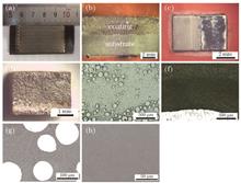
Objective Aircraft must be regularly overhauled during service. To repaint and obtain a new and beautiful coating and detect internal defects in the aircraft body or other key structural components, the original paint layer must be removed from the fuselage. The removal of paint from the aircraft fuselage plays an important role in maintenance. As a green and highly efficient technique, laser depainting has garnered considerable attention in recent years. The process and mechanism of laser depainting both require further investigation. The most commonly used lasers for depainting include CO2 and nanosecond lasers, and they have been discussed and analyzed with respect to cleaning efficiency and removal mechanism. In this study, the effect of laser at different time scales on the cleaning quality of laser paint removal from Al alloy surfaces was explored. The research results lay the foundation for the laser depainting of homemade large C919 aircraft body.Methods Millisecond and nanosecond pulsed lasers were used to clean the epoxy paint coating on the 2024 Al alloy surface. The millisecond laser has a wavelength, maximum pulsed frequency, and maximum laser power of 10.6 μm, 5 kHz, and 2 kW, respectively. The nanosecond laser has a wavelength, pulsed frequency, pulse width, and maximum single pulse energy of 1064 nm, 2--50 kHz, 30--100 ns, and 100 mJ, respectively. During the cleaning process, the laser cleaning physical phenomenon was monitored online using a high-speed camera and a secondary light source with a wavelength of 808 nm. After the laser cleaning experiment, the macroscopic and microscopic morphologies of the sample were observed and investigated using the camera and scanning electron microscopy. Lastly, the physical mechanism of two types of laser paint removal was discussed by combining the thermoelastic vibration and heat conduction models.Results and Discussions Both lasers can effectively remove the coating and obtain a clean substrate surface with appropriate process parameters. However, the paint removal characteristics of the two lasers were quite different. Nanosecond laser paint removal showed considerably higher energy efficiency than millisecond laser paint removal. A layer of charcoal ash remained on the sample surface after millisecond CO2 laser cleaning, which was a combustion product of paint coating. The substrate surface did not melt during the cleaning process. In the case of millisecond laser depainting, a significant amount of black smoke was generated and the paint layer was melted during the cleaning process. During the nanosecond pulse laser cleaning process, strong plasma was observed and large pieces of paint were stripped from the substrate surface. After cleaning a paint layer using millisecond laser depainting, the substrate maintained a state of unmelted surface. However, some defect micropores and microcracks appeared on the surface, which were induced by the thermal stress of the substrate. In the case of nanosecond laser depainting, the substrate surface was completely remelted when the laser power was higher than 250 W. The microstructure formation on the surface was related to a fast cooling process. Under the action of the nanosecond laser, the temperature of the substrate increased to the melting point, thus yielding a thin melting metal. Because of the large cooling velocity, the existence time of the molten pool was short. Hence, the molten pool instantaneously solidified and did not have sufficient time to spread, finally forming the microstructure. The main mechanism of millisecond laser paint removal is vaporization and combustion reaction, while that of nanosecond laser paint removal is the thermoelastic vibration effect.Conclusions To clean a 50-μm-thick paint layer using the millisecond laser, the optimized process parameters include pulse frequency, pulse duration, and laser power of 500 Hz, 0.6 ms, and 500 W, respectively. The optimized process parameters of the nanosecond laser for cleaning a 50-μm-thick paint layer include pulse frequency, pulse duration, and laser power of 5 kHz, 60 ns, and 200 W, respectively. Compared with the nanosecond laser, the millisecond laser induces lesser remelting owing to the deeper thermal diffusion after cleaning of the paint layer. The main mechanism of millisecond laser paint removal is vaporization and combustion reaction, while that of nanosecond laser paint removal is the thermoelastic vibration effect. The energy efficiency of nanosecond and millisecond laser depainting is 300 and 5 J/mm 3, respectively. The difference in the energy efficiency is attributed to thermal diffusion depths and cleaning mechanisms of the two lasers.

Chinese Journal of Lasers
Mar. 08, 2021, Vol. 48 Issue 6 0602103 (2021)
Effect of TiB2 Content on Microstructure and Mechanical Properties of TiB/Ti-6Al-4V Composites Formed by Selective Laser Melting
Lanyun Qin, Jihua Men, Shuo Zhao, Guang Yang, Wei Wang, and Xiangming Wang

Objective With the rapid development of China's aerospace industry, particularly considering the implementation of a series of national programs such as “Project Moonshot” and the “Large Aircraft Program”, the standards for the strength, modulus, wear resistance, and temperature resistance of materials are increasingly high. Ti and its alloys are widely used in the aerospace, biomedical, and chemical industries because of their high specific strength, excellent corrosion resistance, good heat resistance, and high biocompatibility. However, the poor friction performance and low hardness of Ti alloys limit their application in some fields. Particle-reinforced titanium matrix composites (TMCs) can maintain the excellent properties of Ti alloys. These composites have a higher specific strength and specific modulus than Ti alloys; thus, they are expected to become essential structural metal materials in the aerospace industry. In recent years, TMCs have attracted significant interest from researchers in the field of materials. TiB is a ceramic reinforcement with high hardness, and its melting point is as high as 2000 ℃; moreover, there is a very small density difference between TiB and Ti. TiB particles can be produced by an in-situ reaction between Ti and TiB2, which leads to the formation of good interfacial bonding between the matrix and the TiB reinforcement. Recently, selective laser melting (SLM), as a newly developed additive manufacturing technology, has attracted extensive attention because it can directly process powder into materials with complex shapes and high precision. At present, the researches on the formation of TiB-reinforced TMCs via SLM mainly focus on the microstructure, distribution of the reinforcement phase, and microhardness; however, there are a few studies focusing on the mechanical properties of these materials, such as the tensile strength and plasticity. Therefore, analyzing the microstructure, phase composition, and mechanical properties of TiB-reinforced TMCs formed by SLM is necessary.Methods TiB2/Ti-6Al-4V mixed powders after ball milling were used as raw materials. TiB-reinforced TMCs with different B contents were prepared by SLM. The phase composition, microstructure, electron backscatter diffraction (EBSD) results, and α lamella size of the TMCs with different B contents were analyzed by X-Ray diffraction (XRD), optical microscopy (OM), and scanning electron microscopy (SEM), and the results were compared. The microhardness and tensile properties of the TMCs were analyzed by hardness and tensile tests at room temperature. The reasons for the decrease in the α lamella size and the increase in the strength of the TMCs are provided.Results and Discussions The results show that TiB diffraction peaks are observed in the XRD patterns of the TMCs. The microstructure of the TMCs is compact, and the semi-elliptic molten pool is tightly packed to form a good metallurgical bond. The needle-like TiB reinforcement phase is observed under a scanning electron microscope. The EBSD results show that compared with that of Ti-6Al-4V, the α phase of the TMC is noticeably refined. In addition, the microhardness, tensile strength, and yield strength of the TiB/Ti-6Al-4V composites are significantly improved.Conclusions Based on the above results, the main conclusions of this paper are as follows:After mixed powder ball grinding, Ti-6Al-4V powder particles still showed a spherical morphology, and the TiB2 particles were uniformly distributed on the surface of the spherical powder. XRD and SEM studies confirmed that Ti and TiB2 could react to produce needle-like TiB particles during the SLM process. TiB has a B27 structure, where the B atoms have a zigzag and continuous arrangement in a serrated continuous pattern with strong B—B bonds in the [010] direction. Furthermore, TiB has a highly asymmetric atomic structure and a high binding strength; hence, its growth rate is higher in the [010] direction than in the [100], [101], and [001] directions. Therefore, the TiB reinforcement phase tends to have a needle-shaped/rod-shaped morphology. In the TMCs sample with a high B content, the needle-like TiB reinforcement phases are clustered together, and the phenomena of cluster growth and coupling growth are observed. Because of the presence of B and the rapid solidification step of the SLM process, the α lamella size of the TMCs significantly decreases. Compared with those of Ti-6Al-4V prepared by SLM, the microhardness, tensile strength, and yield strength of the TMCs are significantly improved. The excellent mechanical properties of the TMCs are attributed to the hardening and strengthening effects of the TiB particles and the grain refinement of the matrix. When the mass fraction of elemental B is 0.5%,the average size of the α lamellar is 0.49 μm. Compared with those of Ti-6Al-4V, the tensile strength and yield strength of the TMC increase by 25.7% (1396.4 MPa) and 30.8% (1322.2 MPa), respectively.

Chinese Journal of Lasers
Mar. 08, 2021, Vol. 48 Issue 6 0602102 (2021)
Effect of Microstructures of Ultranarrow Gap Laser Welded B950CF Steel Joints on Residual Stress Distribution
Chengzhu Zhang, and Hui Chen

Objective Ultra-narrow gap laser welding (ultra-NGLW) is a type of advanced welding technology for high-strength thick steel plates that use a laser as the heat source in an ultranarrow groove. It has the advantages of high welding accessibility and efficiency, low heat input and residual stress, and low deformation. Ultra-NGLW is suitable for welding thick high-strength steel plates in pressure vessels, ships, pipes, and hydropower equipment. Different from the common arc welded joints, in the process of multilayer filler wire welding, the complex thermal process differently changes the microstructure of each filling layer, resulting in different mechanical properties of each micro-zone. Therefore, the residual stress distribution in the ultranarrow gap laser welded high-strength steel joint is related to its special microstructure.Methods In this paper, the B950CF bainitic high-strength steel and XK-01 wire with diameter of 1.2 mm were considered the research objects. Ultra-NGLW joints with three different thicknesses of 20, 50, and 70 mm were welded using the laser welding system comprising a TRUMPF-10002 high power laser and a Fronius automatic wire feeder.Considering the complex microstructure and highly uneven mechanical properties of the ultra-NGLW joint, the micro-shear test was adopted to study the relationship between the mechanical properties and microstructures of the joint. The micro-shear specimen with a dimension of 1.5 mm×1.5 mm×40 mm, including weld metal (WM), heat-affected zone (HAZ), and base metal (BM), was cut from the different filling layers of the joint.The surface residual stress of the joints with different thicknesses was measured using the μX360n X-ray residual stress tester. Considering the variance of the thermal-physical and mechanical properties of the B950CF high-strength steel with temperature, the properties of the B950CF steel at different temperatures were calculated using the JMat Pro simulation software. Based on the ABAQUS simulation software, a simulation model of the 70-mm-thick ultraNGLW joint was established and the residual stress of this joint was calculated.Results and Discussions The microstructure of the ultra-NGLW joint is considerably more complicated than that of the arc welded joint. The specimen 2 and specimen 3 mainly comprise acicular ferrite and granular bainite. Moreover, the microstructure of the cover layer mainly comprises ferrite and upper bainite, with a small amount of columnar crystals, and low-carbon martensite. The micro-shear test results indicate that the shear stress distribution of the three specimens is “M” type. Approximately 150--200 μm lath martensite is observed at the fusion line, which is brittle and hard with high shear strength. The maximum shear strength is 658.8 MPa. It can be seen from the shear power in the micro-zone of the ultra-NGLW joint that the specimen 2 and specimen 3 exhibit the highest toughness, and the toughness of the cover layer is poor. The toughness of all specimens sharply decreases at the fusion line, which is attributed to the existence of martensite.The residual stress of the ultra-NGLW joints is studied using X-ray nondestructive test and simulation. The results show that the residual stress distribution on the upper surface of the joints with different thicknesses is “W” shaped. The formation of martensite is the main reason for the high compressive stress(-214---476 MPa) at the fusion line. The tensile stress increases with an increase in the joint thickness. The highest residual tensile stress (measured value of 362 MPa and calculated value of 662 MPa) is located in the weld subsurface filling layer. Because the martensite decomposes in the filling layer, the remelting and high temperature tempering cause the volume shrinkage and thus induce the large residual tensile stress. It interrupts the uniformity of the residual stress distribution.Conclusions Results show that the specimen 2 and specimen 3 mainly comprise acicular ferrite and granular bainite. The micro-shear strength (600--630 MPa) is higher than that of the BM (570 MPa), and the weld fusion line comprises lath martensite with the highest micro-shear strength of 658.8 MPa. The toughness of the middle and bottom filling layer is higher than that of the cover layer, which mainly comprises columnar crystals and low-carbon martensite.The residual stress distribution on the upper surface of the ultra-NGLW joints with different thicknesses is “W” type. Owing to the existence of martensite, the compressive stress at the fusion line is -476 MPa (20 mm joint) and the highest tensile stress is 166 MPa (70 mm joint) in the fine-grain zone of HAZ. The tensile stress increases with an increase in the joint thickness.The simulation results of the residual stress distribution of the 70-mm-thick ultra-NGLW joint matches the experimental results. The highest residual tensile stress (measured value of 362 MPa and calculated value of 662 MPa) is located in the weld subsurface filling layer. Because the martensite decomposes in the filling layer, the remelting and high temperature tempering cause the volume shrinkage and thus induce the large residual tensile stress.

Chinese Journal of Lasers
Mar. 03, 2021, Vol. 48 Issue 6 0602101 (2021)
Nanosecond Pulsed Laser-Induced Controllable Oxidation of TiAl Intermetallic Alloys
Guolong Zhao, Hongjun Xia, Liang Li, Min Wang, and Ning He

Objective Poor rigidity of micro milling tools and a high milling force are the main causes of low machining efficiency, poor surface integrity, and severe tool wear in micro milling TiAl intermetallic alloys. In this study, an innovative hybrid machining process comprising laser-induced controllable oxidation assisted micro milling was proposed to address these problems. In the proposed process, a controllable oxidation reaction occurs in the cutting zone, and loose oxides, which are easy to cut, could be synthesized during the hybrid machining, thereby decreasing the milling force and achieving a mass removal rate. Subsequently, micro milling would be applied to the subsurface materials and high quality microstructures would be manufactured. Most importantly, in this study, nanosecond pulse laser-induced oxidation of TiAl intermetallic alloys was studied, and the influence of laser machining parameters together with an assisted gas atmosphere on the oxidation behavior was investigated. The micro-zone oxidation mechanisms of workpiece materials under both laser irradiation and oxidizer were investigated in detail, and the forming mechanisms of loose oxidation were studied. A control strategy of loose oxidation was proposed; then, the oxidation behavior was adjusted subjectively. The results of this study will provide both theoretical and technical supports in micro milling of TiAl intermetallic alloys.Methods TiAl intermetallic alloys were used in this work (Fig. 1). Laser-induced oxidation experiments were performed with high precision nanosecond (ns) pulsed laser equipment composed of a pulsed ytterbium fiber laser (YLP-F20, IPG Photonics Corporation) and CNC air floating platform. The laser spot diameter and pulse repetition frequency were fixed at 57 μm and 20 kHz, respectively. Laser-induced oxidation experiments were performed in a 99.5% pure oxygen-rich atmosphere and an injection velocity of 5 L/min. The laser energy density was varied from 6.86 J/cm 2 to 11.76 J/cm 2, and the laser scanning speed was 1 mm/s, 3 mm/s, 6 mm/s, and 12 mm/s (Table 3). The oxidation behavior in the atmosphere of air, argon (Ar), and nitrogen (N2) under the same laser parameters was studied. A scanning electron microscope (SEM, Hitachi S-4800) was used to observe the morphologies and cross-sections of both the oxide layer and sub-layer. The hardness of TiAl alloys before and after laser-induced oxidation was measured with a Vickers diamond pyramid indenter (HVS-50) with a static load of 196 N and a loading time of 15 s. The phase compositions with the laser energy density after laser irradiation were detected by X-ray diffraction (XRD, Bruker D8). Cu-K(α) radiation with a scanning step of 0.02° and a sweep speed of 6 (°)/min were used. Results and Discussions At the fixed laser pulse repetition frequency and laser spot diameter, the absorbed energy of the irradiated surface increased as the laser energy density increased. When the laser energy density was greater than the ablation threshold of the irradiated material, the oxidation reaction between the irradiated material and oxygen-rich atmosphere occurred, producing the titanium oxides. However, when the laser energy density was too high, the thermal effect accumulated on the surface of the irradiated material ablated the generated oxide (as shown in Fig. 5). The varied laser energy density significantly influenced the topographies of the sub-layer. At low laser energy density, the subsurface was flat, and residual oxides as well as micro-cracks existed. At lower laser energy density, the oxide layer primarily included low valent titanium oxides, such as TiO2 and Ti2O3, as well as Ti3O5 and Al2O3. As the laser energy density increased, stable and high valent titanium oxides were produced, and the phase compositions primarily consisted of anatase TiO2, rutile TiO2, and Al2O3 (Fig. 6). At high laser energy density, the subsurface had a recasting-layer and many tiny micro craters together with large cracks (Fig. 7). In addition, the thickness of the oxide layer and sub-layer increased as the laser energy density increased (Fig. 8). Moreover, the low laser scanning speed produced better oxidation results compared with the results produced under high scanning velocity at the fixed laser energy density and repetition frequency (Fig. 9). It was noted that at low scanning speed, the thickness of the oxide layer was better than that at high scanning speed (Fig. 10). Furthermore, the irradiated material had better oxidation results under the oxygen-rich atmosphere, compared with other assisted gas atmospheres (Fig. 11).Conclusions In this paper, the oxidation behavior of the irradiated material was studied under changing laser energy densities. All other laser parameters remained unchanged. In the oxygen-rich environment, the accumulated energy absorbed by TiAl material increased gradually as the laser energy density increased, which further promoted the oxidation reaction. In addition, the thickness of the generated oxide layer gradually increased. However, when the laser energy density was more than 9.80 J/cm 2, the produced oxides started to melt and a dense recast layer was formed. The heat-affected zone generated by thermal diffusion expanded rapidly and the thickness of sub-layer increased dramatically. At high laser energy density, the oxide layer was primarily composed of anatase TiO2, rutile TiO2, and Al2O3. For the varied range of laser parameters, the oxidation result was better at a lower laser scanning speed. However, the laser scanning speed and assisted gas atmospheres other than the oxygen-rich environment had no effect on the thickness of the sub-layer. Overall, at laser energy density of 8.82 J/cm 2 and laser scanning speed of 1 mm/s, as well as in an oxygen-rich environment, TiAl intermetallic alloys had better oxidation results, where the thickness of the oxide layer and sub-layer was 66 μm and 22 μm, respectively. After laser irradiation, the hardness of the sub-layer (200 HV) was lower than that of the substrate (365 HV, Table 1), which indicated that the laser-induced oxidation can improve the micro machinability of TiAl intermetallic alloys and promote the service life of micro end mills.

Chinese Journal of Lasers
Nov. 08, 2021, Vol. 48 Issue 22 2202102 (2021)
Effect of Defocus Distance on Formability of CX Maraging Stainless Steel by Selective Laser Melting
Liangliang Zhang, Minjie Wang, Jiaqi Zhang, Jianye Liu, Liuhui Niu, and Jinhai Wang

Objective As one of the most promising additive manufacturing technologies, selective laser melting (SLM) is commonly used in metal mold forming. However, there are few types of materials used for SLM forming of the metal mold. Most die steels are prone to crack and porosity because of the effect of carbon content, limiting the application of SLM in metal mold manufacturing. A new type of maraging stainless steel, SS-CX (corrax stainless steel, referred to as CX stainless steel), can exhibit excellent mechanical strength and good corrosion resistance through the intermetallic compound precipitation and has a lower carbon content, which is considered to be an ideal candidate material for manufacturing metal mold. Because of the novelty of CX stainless steel, its SLM forming has not been systematically studied. The process parameters of SLM forming have been widely studied. Among them, defocus distance as one of the important parameters is rarely reported. The spot size and energy density can be adjusted, and the molten pool shape can be effectively controlled by changing the defocus distance, which is helpful to improve the production efficiency and obtains high-density parts. This study reports the CX stainless steel samples formed through SLM based on defocus parameters, combined with microstructure observation, phase analysis and experimental research, and the sample’s printing quality and forming performance. We believe that the research results obtained will provide a valuable reference for the SLM forming of CX stainless steel and help expand SLM’s range of materials used for metal mold manufacturing.Methods First, the SLM forming process of CX stainless steel is optimized and a reasonable process window is established by conducting the single weld channel test combined with the cross-section observation. Then, the square and tensile specimens are formed through SLM based on different defocus distances. The effects of defocus distance on the sample’s density, hardness, and surface roughness are analyzed through optical microscopy and scanning electron microscopy. Then, the microstructure and phase composition of the sample are studied using metallurgical microscope and X-ray diffraction. The effect of the mechanical properties of the sample is studied before and after heat treatment. The samples’ microstructure evolution and strengthening mechanism after solution, aging, and solution aging heat treatment are then investigated using metallographic observation, scanning electron microscopy, X-ray diffraction, energy dispersive spectroscopy, and hardness testing. Furthermore, the variation of mechanical properties of the sample before and after heat treatment is investigated in combination with the tensile test.Results and Discussions In the SLM forming process window, the welding channel in the stable melting region is continuous and straight and the cross section shows a fine wetting effect (Fig.6). The density and hardness of the sample are first increased and then decreased with the change of defocus distance, whereas the variation of surface roughness is opposite (Fig.12). The main composition of the sample is martensite and austenite. The grain refinement is visible as the defocus distance increases, which is beneficial in promoting martensitic transformation. Simultaneously, the tensile fracture transitions from quasi-cleavage to ductile fracture (Fig.18), the number of dimples increases, and the mechanical properties considerably improve. However, excessive defocus distance leads to incomplete powder melting and reduces the sample’s mechanical properties (Table 4). In addition, some differences are present in the microstructure and tensile fracture morphology of different heat-treated samples. After solution aging heat treatment, the boundary of the welding channel disappears; a large number of lath martensite exist in the structure. Meanwhile, the hard second phase particles of NiAl are precipitated to produce a precipitation strengthening effect. Consequently, the hardness and tensile properties of the sample are considerably improved, the tensile fracture appears as river-like morphology with a few shallow deformation dimples, exhibiting quasi-cleavage fracture characteristics (Fig.27).Conclusions The single weld channel test is used in this study to determine the SLM process window of CX stainless steel, which includes severe melting, stable melting, and incomplete melting regions. The molten liquid phase, for example, exhibits a good melt-wetting effect in the stable melting region. The shorter defocus distance causes an excessively high laser energy density, molten pool instability, and increased spheroidization. The results show that the density and hardness of the sample are reduced and the surface roughness is increased. The tensile characteristic shows quasi-cleavage fracture. With the increase in the defocus distance, the suitable energy density and spot size are conducive to forming a good metallurgical bond between the adjacent weld channels and layers and the sample’s mechanical properties are improved. Under the condition of 3.5 mm defocus distance, the sample’s maximum cross-section and longitudinal-section hardness are 35.94 HRC and 36.82 HRC, respectively, and the surface roughness is 7.315 μm. The tensile fracture mechanism is transformed into ductile fracture characteristics, and the maximum tensile strength is 1218 MPa. Simultaneously, the sample’s mechanical properties are considerably improved after the solution aging heat treatment due to the precipitation and precipitation strengthening effect of the hard second phase NiAl. The maximum hardness of the cross section and longitudinal section is 43.17 HRC and 44.52 HRC, respectively, and the tensile strength is 1746 MPa, which is 43.35% higher than that of the printed sample. When the defocus distance increases excessively, the laser energy density and penetration depth decrease and the liquid melt’s diffusion and infiltration effects become poor. Unmelted metal powder is present between the layers, resulting in the decrease of the density and mechanical properties of the sample.

Chinese Journal of Lasers
Oct. 28, 2021, Vol. 48 Issue 22 2202101 (2021)
Microstructure and Tensile Properties of SiC Reinforced Aluminum Matrix Composite Prepared by Selective Laser Melting
Tianchun Zou, He Zhu, Minying Chen, Siyuan Mei, and Xudong Yang

Objective Selective laser melting(SLM) is an important method to realize functional optimization design and manufacture lightweight metal parts. The parts fabricated by SLM possess have a fine microstructure and excellent mechanical properties due to the rapid cooling rate. Some typical metals, such as aluminum alloys, Ni alloys, and Ti alloys, have been manufactured successfully by SLM and are used widely in the aerospace, automobile, and marine industries. In recent years, aluminum matrix composites have attracted considerable attention because of the advantageous properties of the matrix and reinforcement materials. Compared to other reinforced particles, SiC particles are the most common ceramic reinforcement because of their easy availability, low cost, and high hardness. However, few studies have examined the relative density, microstructure, and properties of SLMed SiC/Al composites, particularly the tensile properties. In this study, 5%SiC/AlSi7Mg composite specimens were prepared by SLM at different process parameters, and an almost entirely dense specimen was obtained. SiC particles and Al4SiC4 phases formed during the in situ reaction were distributed uniformly throughout the aluminum matrix, and strong metallurgical bond existed at the interface. Such aluminum matrix composites posse high tensile strength and yield strength but low ductility compared with the SLMed aluminum alloy. The fracture mode of the SLMed composites was mainly brittle fracture.Methods The original powders used in this study were SiC powders and gas atomized AlSi7Mg powders. The mixed powders with 5% SiC powders were prepared using a V-type mixer. The SiC/AlSi7Mg composite specimens were then fabricated with SLM 125 equipment using different SLM process parameters in an argon atmosphere. Subsequently, the Archimedes method was used to measure the relative densities of the composite specimens. The microstructure of the SLMed composites was observed by optical microscopy and scanning electron microscopy after grinding, polishing, and etching in Keller reagent. The phase identification of the specimen was analyzed by X-ray diffraction. The tensile properties were examined using an electronic universal testing machine at room temperature. In addition, the fracture morphology of the composite was also characterized by scanning electron microscopy.Results and Discussions With increasing scanning speed and hatch spacing, the relative densities of the SLMed SiC/AlSi7Mg composites increased initially and then decreased (Fig.4). The relative density of the composite reached up to 99.2 % under the optimized process parameters (laser power of 300 W, scanning speed of 1400 mm/s, hatch spacing of 0.12 mm, and layer thickness of 30 μm). The typical fine zone, coarse zone, and heat-affected zone also can be found in the microstructure of the SLMed composite. New needle-like Al4SiC4 phases formed during the SLM process because of the in situ reaction of SiC particles and molten aluminum matrix. The SiC particles and Al4SiC4 phases were distributed uniformly in the matrix due to the Marangoni flow. The in situ reactions occurring on the surface of SiC particles promoted the wettability of the SiC particles and molten aluminum matrix. No pores or cracks were observed in the interface, indicating a strong metallurgical bonding. The SiC and Al4SiC4 reinforced phases in the matrix enhanced matrix strength that could bear the stresses transferred from the matrix. However, they also hindered the dislocation movement and interface migration, and the deformation resistance of the composite was improved. The tensile strength and yield strength of the SLMed composite increased to 452 MPa and 280 MPa, respectively, but the elongation decreased to 4.5%. The cleavage plane observed in the fracture morphology also showed brittle fracture.Conclusions The SiC/AlSi7Mg composite specimens were manufactured successfully by the SLM process. The relative density of the SLMed composite increased initially and then decreased with increasing scanning speed and hatch spacing. The SLMed composite exhibited a relative density of 99.2% under the optimized parameters. The microstructure of the composite was similar to the SLMed aluminum alloy, where the typical fine zone, coarse zone, and heat-affected zone exist. The new Al4SiC4-reinforced phases were formed in the aluminum matrix and at the interface of the SiC particles and matrix caused by the in situ reactions between the SiC particles and molten aluminum alloy. Good metallurgical bonding in the interface was formed. The SiC and Al4SiC4-reinforced phases were distributed uniformly throughout the aluminum matrix. The strength of the SLMed composite was improved by the addition of SiC particles and the formation of an Al4SiC4 phase, but the ductility decreased compared to SLMed AlSi7Mg. The tensile strength, yield strength, and elongation of the SLMed composite were 452 MPa, 280 MPa, and 4.5%, respectively. The fracture mode of the SLMed composites was mainly brittle fracture.

Chinese Journal of Lasers
May. 19, 2021, Vol. 48 Issue 10 1002123 (2021)
Microstructure and Properties of Iron-Based Alloys Coatings Prepared by High-Speed Laser Cladding
Yifei Xu, Yaoning Sun, Guojian Wang, and Yongliang Gui

Objective With the release of “Energy Planning for the Core Area of the Silk Road Economic Belt” in 2018, Xinjiang's coal industry is about to enter an unprecedented significant leap-forward development. In the manufacturing industry, it is paramount to develop new coating technologies for wear and corrosion protection of large and high-quality components. The most common process for wear and corrosion protection is hard chromium plating. Its biggest drawback concerns environmental protection. Moreover, the electrochemical processes consume much energy and become less economical as electricity cost increases. Therefore, new alternatives to hard chromium plating are under investigation, and high-speed laser cladding (HSLC) is such an alternative. The benefits of laser cladding (LC) are low heat input, low dilution with the substrate, less material consumption, and overall good performance. HSLC overcomes the efficiency obstacle of conventional LC technology, as well as provides an environmentally friendly and cost-effective production mode for the fabrication of thin coatings on large parts. To meet the tough health and environmental demands along with industries need for lower costs, high-quality iron-based alloy coating material suitable for HSLC was prepared. Through the analysis of its macro-morphology, microstructure, hardness, and corrosion resistance, the basis for improving the corrosion resistance and service life of hydraulic props is provided.Methods In this study, 45 steel was selected as the substrate. Iron-based alloy powder was used as coating materials. A ZKZM-2000 fiber laser system was employed. A defocus of 15 mm was adopted. The diameter of the beam spot was 1.2 mm. The powders were fed by a powder feeder, and argon was employed as the carrier gas. The main distinctions between HSLC and conventional LC are the melting mode of powder and the formation mode of the molten pool. For the former, the focal planes of the powder stream and laser beam are above the molten pool. Under such conditions, most of the powders are heated and melted before being injected into the molten pool. For the latter, the powders are mainly melted in the molten pool. At 50% overlapping rate, 260 μm thickness and ~7.1% dilution rate of the coating can be obtained. Macroscopic features and microhardness were investigated using an ultra-depth three-dimensional microscope and a microhardness tester, respectively. Test specimens were etched using aqua regia to analyze the microstructure and phase components of the coatings using scanning electron microscopy, energy dispersive spectrometry, and X-ray diffractometry (XRD). The corrosion behavior of the coating was evaluated using CHI660E system at room temperature (20 ℃). The medium was 3.5% NaCl solution.Results and Discussions The cladding efficiency of the HSLC process could reach up to 0.243 m 2/h. Under the same process parameters, the growth laws and trends of single-layer, double-layer, and four-layer coatings are basically the same, indicating that the increase in the number of cladding layers has little effect on the microstructure of the coating. The HSLC samples were formed uniformly at the macro-level, and the surface roughness was controlled at 21.38 μm, which was less than 10% of the conventional LC samples (Fig. 2). The geometric dilution ratio is ~7.1%, which is uniform and dense, in addition to good metallurgical bonding to the substrate. The low dilution ratio obtained from the HSLC process is due to low heat input and specific metallurgical forms. The result of the XRD pattern for HSLC coating indicates that the coating mainly consists of α and γ phases (Fig. 7). The ultrafine dendrites with an average grain diameter of less than 2.8 μm are formed (Fig. 6). The difference between grain sizes is mainly determined by the cooling rate. High cladding speed contributes to increasing cooling rate, which causes low dilution ratio and dendrites refinement. The microhardness of the coating is about three times as high as the substrate. In a 3.5% NaCl solution, the corrosion current of the coating dropped by two magnitudes compared to substrate, which indicates that a more uniform microstructure of HSLC coatings leads to a higher corrosion resistance. Conclusions Cladding layers of iron-based alloy powders were prepared on 45 steel surface using HSLC. The macroscopic features, microstructure, and corrosion resistance were comparatively investigated. The crack-free layers obtained with HSLC present good metallurgical bonding with the substrate and a high degree of uniformity and compactness. At a scanning speed of 3600 mm/min, the coating thickness is up to 260 μm, with a dilution rate of ~7.1%. Compared with the dendrite characteristics by messy dendrites of the conventional LC, the microstructure of the coating prepared by HSLC is mostly dendrites. Moreover, its microstructure of dendrite is finer, the difference in composition between grains is smaller, and the distribution of grains is more uniform. The microhardness of the HSLC coating is three times as high as the substrate under the joint action of grain refinement and solid solution strengthening. The corrosion behavior in 3.5% NaCl solution indicates that the HSLC coating has good corrosion resistance, and its corrosion current density Icorr is two and three orders of magnitude lower than that of conventional LC coating and hard chromium plating, respectively. Therefore, the coating obtained from HSLC can satisfy the tough health and environmental demands. In addition to improving the work efficiency, the waste of follow-up processing materials and resources is reduced.

Chinese Journal of Lasers
Apr. 27, 2021, Vol. 48 Issue 10 1002122 (2021)
Simulation and Experimental Research on the GH3536 Molten Pool Laser Cladding on Inclined Substrate
Pengfei Wang, Kun Yang, Mingzhi Chen, Zhandong Wang, Yi Lu, Guifang Sun, and Zhonghua Ni

Objective GH3536 is a typical nickel-based solid solution strengthened high-temperature alloy with good oxidation resistance, corrosion resistance, as well as cold and hot processing formability and weldability, which is suitable for manufacturing aero-engine combustion chambers and other high-temperature components. The failure mode of the combustion chamber is mainly mechanical damage and shell cracks. Laser-cladding technology can be used to repair the failures, which can effectively reduce the combustion chamber test's cost. However, the topography of the area to be repaired is mainly curved or inclined surface, and the operation space is limited. Therefore, it is necessary to study the repair process and role of laser-cladding technology on the inclined substrate. In this study, we analyzed the influence of factors such as inclination angle and gravity on the temperature field, flow field, and final contour of the molten pool during GH3536 cladding on the inclined surface with both experimental and simulation methods and laid a foundation for the application of laser-cladding technology to repair inclined substrates, such as combustion chambers.Methods This study investigated the process and role of GH3536 laser cladding on inclined surfaces with both experimental and simulation methods. First, we used the orthogonal experiment to analyze the influence of factors such as laser power and powder-feeding flow rate on the melting height and profile during GH3536 laser cladding on a plane substrate. Then, we performed a controlled variable experiment of laser cladding on an inclined surface to analyze the influence of factors such as the inclination of the substrate, laser power, and powder-feeding flow rate on the melting height. Afterward, we established a computational-fluid-dynamics model to simulate GH3536 laser cladding on inclined surfaces and compared the cladding profile and penetration depth via simulation and experiment to verify the effectiveness of the model. Finally, we investigated the influence of the inclination angle of the inclined surface on the front contour, internal temperature field, and the flow field of the cladding layer.Results and Discussions In the orthogonal experiment, within a set range of the experimental parameters, when the laser power is selected as the lowest value of 1000 W, and the powder mass flow rate is selected as the maximum value of 18 g/min, the melting height is the largest (Fig.4). When the substrate starts to tilt, the melting height gradually decreases with the increase in the inclination angle. A moderate increase in the laser power and powder feed mass flow can compensate for the decrease in the melting height. Further, at the same inclination angle, the melting height increases during upward cladding (Fig.8). In the simulation model, comparing the quasi-steady state molten pool contours under different substrate inclination angles, the slope angle of the molten pool front contour decreases with the increase in the inclination angle, and the front slope angle during upward cladding is slightly smaller than that of downward cladding (Fig.10). In addition, comparing the internal flow field of the molten pool under different substrate inclination angles, the front and rear flow fields appeared in the quasi-steady molten pool, and the latter is stronger. They are separated by the high-temperature zone of the molten pool. The substrate inclination has a significant influence on the flow field in the molten pool. During upward cladding, gravity strengthens the rear flow field and weakens the front flow field, thereby accelerating their divergence. At their divergent positions, the contour of the molten pool also shows obvious slope angle changes (Fig.12). The changes in both flow fields correspond to the changes in the front of the upper molten pool and the changes in the melt height. It can be inferred that the flow fields have a significant influence on the profile of the molten pool—the front flow field dominates the front slope angle of the molten pool, while the rear flow field dominates the molten pool height.Conclusions The tilt of the substrate decreases the laser energy and powder concentration at the cladding area, thereby reducing the cladding height considerably. A moderate increase in the laser power and powder delivery mass flow rate can compensate for the decrease. The Marangoni convection in the molten pool is divided into two flow fields—the front and rear flow fields. The latter dominates the height of the cladding layer, while the former dominates the slope angle of the cladding layer. The difference in gravity influence due to the inclination of the substrate has a significant influence on the contour of the molten pool, especially the front contour. In addition, the difference in the cladding direction will significantly change the effect of gravity on the internal flow field, resulting in a completely different front contour and front slope angle: when the inclination angle is positive, the gravity component promotes the rear flow field, accelerates the divergence of both flow fields, leading to the concave phenomenon of the molten pool, and reduces the front slope angle and has higher melting height compared with a negative inclination angle.

Chinese Journal of Lasers
Jun. 03, 2021, Vol. 48 Issue 10 1002121 (2021)
Effect of Grain Size on Mechanical Properties of Double Laser-Beam Bilateral Synchronous Welding Joint
Dan Chen, Ting Liu, Yanqiu Zhao, Leilei Wang, and Xiaohong Zhan

Objective Compared with the traditional Al-Li alloy, the Al-Li alloy weighs less and has high stiffness, making it more conducive for manufacturing aerospace components. However, because of its low boiling point, high thermal expansion, and high thermal conductivity, a heat source with concentrated energy is more suitable for welding Al-Li alloys. Based on the unique welding structure of aircraft fuselage panels, a novel technology of dual laser-beam bilateral synchronous welding (DLBSW) is proposed and applied in the manufacturing process to ensure the fuselage shape and improve the welding efficiency and quality. During the DLBSW process, improper heat input affects the temperature gradient and solidification speed of the metal in the molten pool, resulting in coarse grains of the T-joints, which is unconducive to improve the macroforming and overall mechanical properties of welded components. Here, we analyze the grain morphologies and sizes in different regions of the joints under different welding parameters and explored their influence on the mechanical properties of welded joints, providing reference and guidance for further improvement of the mechanical properties of welded joints.Methods Here, 2060 (500 mm×125 mm×2 mm) and 2099 Al-Li alloy sheets (650 mm×28 mm×2 mm) are used as the skin and stringer, respectively. A 1.2 mm diameter ER4047 Al-Si welding wire is used as the filler material. The chemical compositions of the base metal and welding wire are shown in Table 1. Before welding, the sample surface should be chemically cleaned to remove the oxide film and oil stain. The welding experiment is conducted using a double laser-beam welding system (Fig. 1). Based on the preliminary welding test and comprehensive analysis of the welding seam forming quality, four better welding parameters are selected in the experiment (Table 2). After welding, the metallographic sample of the cross-section of the T-joints is cut by wire cutting technology and inlaid with epoxy resin. Next, the metallographic sample is polished and etched with Keller's reagent. Furthermore, the microstructure and grain size of the joints are analyzed using a metallographic microscope. Also, tensile tests are performed on the specimen until fracture, and the fractured specimen surface is observed by transmision electronic microscopy(SEM).Results and Discussions Based on the T-joint microstructure, the grain morphology from the upper fusion line to the weld center in the solidification process are equiaxed fine grains, columnar dendrites, and equiaxed dendrites (Fig. 3). The average width of EQZ WEQZ increases with the increase in welding heat. With a heat input of 43.64 J/mm, the equiaxed fine crystal band narrowed down, its width is 2--3 times as long as the grain size, whereas with a heat input of 48.00 J/mm, the width of the crystal band increases to 4--5 times as long as the grain size (Fig. 4). When the heat input is low, because of a decrease in the temperature gradient, the dendrites of equiaxed fine grains grow and become columnar crystals, decreasing the WEQZ, even though it cannot be observed. Also, with low input, the ratio of the temperature gradient to the crystallization speed in the columnar crystal is larger, and the growth of the columnar crystal nucleus becomes difficult. Thus, with low heat input, the columnar crystal grains are smaller. From the microhardness distribution results, the microhardness values of 2060 and 2099 Al-Li base metals are the highest, followed by the heat-affected zone and weld center. The microhardness in the fusion zone is the lowest (Fig. 5). No EQZ exists at the weld toe, which is composed of coarse and short columnar crystals. The stress concentration in the weld toe because of the structural mutation and the grain size is more significant than that in the EQZ zone, where dislocation slip is more likely to occur under the action of an external force. Therefore, the weld toe is the starting point of the T-joint fracture (Fig. 6).Conclusions In this study, the heat input in the range of 43.64--48.00 J/mm of DLBSW welding is investigated to explore the mechanical properties of 2060 and 2099 Al-Li alloy T-joints affected by different grain morphologies and size characteristics. The mechanical properties of the weld can be controlled by changing the welding process parameters, which affect the grain structure characteristics of the welding joint, especially near the fusion zone. With the increase of heat input, the heat-affected and partially molten zones in the T-joint widens, and the width of equiaxed fine-grained zone increases; the grain size of equiaxed fine-grained zone first decreases and then increases with the increase in welding heat input, and the grain size of columnar dendrite increases with the increase in heat input. Based on the average hardness, tensile properties, and fracture morphology of the joint, it can be concluded that with a heat input of 46.16 J/mm, the mechanical properties of T-joint are the best, and the tensile strength can reach 335.7 MPa. Hence, reducing the grain size in the EQZ of welded joints can significantly improve the mechanical properties. Therefore, the mechanical properties of the joint can be improved by changing the welding process parameters to limit the grain growth trend.

Chinese Journal of Lasers
Apr. 27, 2021, Vol. 48 Issue 10 1002120 (2021)
Microstructure and Corrosion Resistance of Laser B4C/Cr Alloyed Layer of GCr15 Steel
Bingqian Tong, Zhenxing Li, Qunli Zhang, Zhehe Yao, Zhijun Chen, and Jianhua Yao

Objective GCr15 steel is a high-carbon steel with high hardness and good wear resistance. It has been widely used in many fields, such as the automotive industry, aviation equipment, transport ships. However, the corrosion resistance of GCr15 steel is poor, and its components suffer early fatigue failure due to corrosion. It can be characterized by the phenomenon that when it is used in marine equipment, its service life is short due to the erosion effect of Cl -. The corrosion resistance of GCr15 steel can be improved by adjusting its microstructure. However, simultaneously, the corrosion resistance is closely related to the composition. There are some limitations in improving the corrosion resistance by simply adjusting the microstructure. Laser surface alloying (LSA) is a typical surface strengthening technology, which is often used to adjust the distribution of elements and microstructure nearing the metal surface, so it has a broad application prospect in improving the mechanical properties and corrosion resistance of metal materials. Therefore, in this study, LSA is used to prepare Cr alloyed layer on the surface, and the effect of B4C on the phase, hardness, and corrosion resistance of the alloyed layer is studied. Methods Using laser alloying, a corrosion-resistant high Cr alloyed layer is prepared on the surface of GCr15 steel. Before alloying, the substrate is preheated to avoid cracks. Then, the microstructure and phase of the alloyed layer are analyzed by optical microscope (OM), scanning electron microscope (SEM), energy dispersive spectrometer (EDS), and X-ray diffractometer (XRD). The electrochemical performance is tested by a conventional three-electrode system. The saturated calomel electrode is used as the reference electrode, the sample as the working electrode, and the platinum electrode as the auxiliary electrode. In this work, 3.5% NaCl solution is used as the corrosive medium, the scanning speed is 1 mV/s, and the test time is 1800 s. The corrosion resistance is analyzed by polarization curve and impedance spectrum.Results and Discussions As shown in Fig. 2, the alloyed layers obtained using B4C/Cr powders with different mass ratios have no defects such as cracks and pores, the interface between the alloy layer and the substrate is metallurgically bonded. The distribution of Cr in the alloy layer is analyzed by EDS. It is found that the Cr content in the alloy layer is higher than that of the matrix, and the thickness of the alloy layer is about 400 μm. The remelting occurred in the overlapped region. Due to the convection in the molten pool, elements in the alloy layer are redistributed, which will promote homogenization of the composition (Fig. 3 (b)).The microstructure of the alloyed layer is dendrite. In the process of laser alloying, due to the heat conduction of the substrate, there is a large temperature gradient in the direction perpendicular to the substrate, the direction of dendrite growth is approximately perpendicular to the substrate. Compared with the alloyed layer obtained using Cr powder, the microstructure of the alloyed layer obtained using B4C/Cr mixed powder is finer (Fig. 4), and there are two new strengthening phases of Fe2B and CrB in the alloyed layer (Fig. 6). Furthermore, the addition of B4C can improve the hardness of the alloyed layer (Fig. 7). Moreover, the newly formed borides and carbides can be used as the core of heterogeneous nucleation, which can increase the nucleation rate and thus refine the microstructure of the alloyed layer. Alternatively, there are more carbides CrB and Fe2B in the alloyed layer, which serves as a dispersion strengthening.By analyzing the Nyquist curves of impedance spectra of different samples, it is found that they have similar capacitive arc characteristics (Fig. 8 (a)). The corrosion potential (Ecorr) and corrosion current density (Icorr) are obtained from Tafel curve extrapolation. The results are listed in Table 3. It is found that corrosion resistance of the alloy is improved because Cr is a passivation element, and an increase in Cr content on the surface is beneficial to delay the corrosion rate. Compared with the alloyed layer obtained using pure Cr, the alloyed layer obtained using B4C/Cr mixed powder has a higher corrosion potential and lower corrosion current density, which indicates that it has better corrosion resistance. This is because the microstructure is refined by adding B4C, and the alloyed layer obtained using the B4C/Cr mixed powder with a mass ratio of 1∶16 has a higher content of CrB, which is beneficial to increase the corrosion factor. The hard phase enriched with Cr and a solid solution of (Fe, Cr) is firmly combined with other phases, which reduces the degree of grain boundary corrosion (Fig. 10).Conclusions In this study, a high Cr corrosion-resistant alloyed layer is prepared on the surface of GCr15 steel by laser alloying. The alloyed layer has good metallurgical bonding with the substrate material, and the microstructure is a typical dendritic structure. Compared with the alloyed layer obtained using Cr powder, the microstructure of the alloyed layer obtained using B4C/Cr mixed powder is more refined, and there are two new strengthening phases of Fe2B and CrB in the alloyed layer. The addition of B4C improves the hardness and corrosion resistance to a certain extent. When the mass ratio of B4C and Cr powder is 1∶16, the microhardness of the alloyed layer is about 621 HV, which is 2 to 3 times the hardness of the substrate, and its corrosion resistance is better.

Chinese Journal of Lasers
Apr. 27, 2021, Vol. 48 Issue 10 1002119 (2021)
Comparative Study on Cavitation-Resistance and Mechanism of Stellite-6 Coatings Prepared with Supersonic Laser Deposition and Laser Cladding
Jingyong Sun, Yuliang Yan, Bo Li, Qijian Shi, Tianshu Xu, Qunli Zhang, and Jianhua Yao

Objective As the core part of energy conversion of industrial steam turbine, the blade plays an important role in the safe operation of a steam turbine. However, the last stage blade usually suffers from cavitation, leading to severe vibration, blade fracture, and other malignant events. Since cavitation usually starts from the blade surface, it is an economic and effective method to prepare anti-cavitation coating on the blade surface by coating technology, which has attracted significant attention. Cobalt-based alloy Stellite-6 is widely considered as one of the most ideal materials for cavitation-resistant coating of steam turbine blades due to its good corrosion resistance, wear resistance, and high-temperature resistance. Traditional coating technologies, such as laser cladding (LC) and thermal spraying, have adverse thermally-induced effects, such as phase transformation, dilution, and decomposition. Supersonic laser deposition (SLD) technology is a material deposition technology combining laser and cold spraying. It can realize the deposition of high-strength materials (e.g., Stellite-6) while avoiding the adverse effects caused by massive heat input. In this study, SLD and LC are employed to prepare Stellite-6 coating. The cavitation-resistant properties of the two kinds of Stellite-6 coatings are evaluated. The underlying mechanisms are clarified based on microstructure, dilution ratio, elastic modulus, and hardness. This study is expected to provide process support and theoretical guidance for the fabrication and performance optimization of cavitation-resistant coating for steam turbine blades.Methods Stellite-6 coating is prepared on 17-4 PH stainless steel through SLD and LC processes. The cavitation-resistant properties of the two kinds of coatings are tested using an ultrasonic cavitation method according to ASTM G32. The cavitation sample is assembled with the bottom of the ultrasonic horn through a thread connection. The test medium is NaCl (the mass fraction is 3.5%) solution and the constant temperature is 25 ℃. During the test, the coating side of the cavitation sample is immersed in the medium solution for 20 mm, the ultrasonic vibration frequency is 20 kHz, and the peak-peak amplitude is 50 μm. The duration of the cavitation test is 14 h. After every 1 h of cavitation, the sample is taken out, cleaned with alcohol, and dried. Then, the sample is weighed with an electronic scale (accuracy of 0.001 mg) three times to take the average value. Mass loss is recorded before continuing the experiment. The cavitation-resistance is characterized by cavitation mass loss and cavitation rate.Results and Discussions As shown in Table 1, in the first 2 h, Stellite-6 coatings prepared by LC and SLD processes have similar cavitation mass loss and cavitation rate, which corresponds to the incubation stage of the cavitation process, and the cavitation rate is slow (less than 1 mg/h). In the following stage, the cavitation mass loss of the LC sample increased rapidly, and the cavitation rate increased rapidly and remained above 2 mg/h. However, the cavitation mass loss of SLD sample increased slowly, and the cavitation rate remained at about 0.7 mg/h during the whole cavitation process and increased to more than 1 mg/h only when the cavitation time is 14 h.The LC coating has a typical coarse cladding dendrite structure (Fig. 7 (b)), while the SLD coating retained the fine dendrite structure inside the deposited powder particles (Fig. 7 (d)), which is related to the laser energy input during the two processes. The laser energy density is calculated to be 72.79 J/mm2 and 35.03 J/mm2 for LC and SLD processes, respectively. The fine dendrite structure of the original powder particles remained in the SLD coating due to lower heat input. It is reported that grain refinement is essential for improving the cavitation-resistance of materials. Thus, the finer dendrite structure in SLD coating is responsible for its better cavitation-resistance than LC coating.As shown in Fig. 8 (a), the LC coating had severe element dilution of Fe from the substrate while Fe element is almost not detected in SLD coating (Fig. 8 (b)). The Fe element from the substrate changes the original chemical composition of the Stellite-6 alloy and affects its cavitation-resistance. The higher dilution degree of the LC coating is responsible for its inferior cavitation-resistance compared to that of the SLD coating. SLD is a material deposition process based on plastic deformation of powder and substrate. During the coating preparation process, the material will undergo work-hardening; thus, its hardness is higher than that of LC coating (Fig.9), which is essential for cavitation-resistance.To investigate the cavitation mechanism of the Stellite-6 coating prepared through LC and SLD, the surface morphology of the coating after different cavitation time is analyzed. The phase/grain boundary is the preferred position of cavitation in the LC coating, indicating a uniform surface morphology (Fig.10). The pores between particles are the initial position of cavitation in the SLD coating, indicating a non-uniform cavitation process (Fig.11).Conclusions In this study, the cavitation-resistant properties of Stellite-6 coatings prepared by SLD and LC processes are compared. The reasons for the advantages and disadvantages of the two coatings are clarified from the perspective of micro characteristics. Through the analysis of cavitation surface morphology, the differences in cavitation mechanism between the two coatings are elucidated.Due to the lower laser input energy density in the SLD process, the SLD coating has a finer dendrite structure and a lower element dilution ratio than the LC coating. Besides, SLD is a powder deposition process based on material plastic deformation, which induces a work-hardening effect. Thus, SLD coating has a higher hardness/elastic modulus ratio than LC coating. These factors lead to better cavitation-resistance of SLD coating than LC coating.LC coating is formed through the material melting/re-solidification process, resulting in a typical dendrite structure. The phase/grain boundary is the preferred position of cavitation in the LC coating, which shows a uniform surface morphology. Since SLD relies on mechanical bonding instead of metallurgical bonding to fabricate coatings, there will be pores between particles due to poor bonding. These pores are the initial position of cavitation in SLD coating, showing a non-uniform cavitation process.

Chinese Journal of Lasers
May. 19, 2021, Vol. 48 Issue 10 1002118 (2021)
Femtosecond Laser Etching of Aluminum Film on Tedlar Composite Surfaces
Kaiwen Shang, Gan Wu, Xiaoli Liu, Jianping Yang, and Rui Wang

Objective The materials system of Tedlar composite-aluminum film, which has the advantages of high specific strength and modulus, light weight, good stability, and high reflectivity, can be used for frequency choice (Frequency Selecting Surfaces, FSS) preparation. FSS are widely used in the field of spatial filters, radar antenna masks, antenna array radar scattering cross sections, reflectors for transmitted and reflected electromagnetic waves in different spectra, and so on. With the development of satellite antennas to high-frequency bands, the graphics size of the FSS unit is required to be smaller and smaller, and the dimensional accuracy is required to be higher. At present, the market has an urgent processing precision demand of less than 10 μm, the traditional microprocessing technology being unable to meet the technical requirements. The technology of a femtosecond pulse laser has the characteristics of short pulse width and high peak power. It has little thermal effect on the etching process of composite-aluminum film, and the overall effect of etching the boundary of graphic unit is better than with a nanosecond laser. Therefore, there are important theoretical significance and application value to carrying out relevant studies on femtosecond laser etching of aluminum film on a Tedlar composite substrate.Methods In this paper, the effects of laser power, laser spot diameter, and scanning rate on the properties of Tedlar composite substrate -2 μm aluminum film using femtosecond laser etching technology are studied by the method of combining theoretical simulations and experiments. The optimal technological parameters are obtained by theoretical optimization using ANSYS 14.0 software. The femtosecond laser etching composite technology under different process parameters is verified using Pharos-type equipment, and the surface morphology and sample size of the etched-processed samples are tested using noncontact three-dimensional surface graphic analysis equipment.Results and Discussions The simulation results show that the femtosecond laser etching pulse laser beam has enough energy to make the crystal lattice temperature exceed the melting point of aluminum in a very short time so that the aluminum film material on the composite substrate surface expands and is etched away rapidly (Fig.2). The interface temperature increased as the power of the femtosecond laser etching increased. When the laser power increased from 3.0 W to 5.5 W, the interface temperature between the Tedlar composite and aluminum film increased from 417.68 K to 513.19 K, causing damage to the Tedlar substrate and affecting the performance of the intrinsic material (Figs.3 and 4). When the laser scanning speed increased from 350 mm/s to 600 mm/s, the discontinuous point size increased from 1.2 μm to 2.7 μm in the femtosecond laser etching process, resulting in the size error of the laser etching process becoming greater than 10 μm (Fig.5). The experimental result shows that the larger the laser spot diameter and the smaller the laser spot overlap ratio are, the higher the scanning etching error is, while a smaller laser spot size and higher laser overlap ratio are conducive to the improvement of laser etching accuracy. When the spot diameter is 40 μm, the overlap ratio is 25%, and the etching error is 6.77 μm so that the technical accuracy requirements of less than 10 μm are fully met (Fig.6). When the laser power is less than 4.0 W, there is a large amount of residual aluminum. When the laser power is greater than 4.0 W, the substrate is damaged around the etched area. When the laser power is 4.0 W, the aluminum film on the substrate is completely removed and Tedlar composite substrate is not damaged (Fig.7). When the laser scanning rate is 500 mm/s, the spot overlap rate is 37.5% and metal-aluminum film is completely etched and removed. However, when the laser scanning rate is 550 mm/s, the spot overlap rate is 25%. At this time, the metal-aluminum film is etched clean and only a very small amount of metal aluminum remained. When the scanning rate continued to increase to 600 mm/s and 650 mm/s, the spot overlap rate is 0, but there is a large amount of etched metal-aluminum residue. With the increase of scanning rate, the residual aluminum content increased (Fig.8). The simulation results are consistent with the experimental results.Conclusions Under the conditions of laser output power is 4.0 W, spot diameter is 40 μm, and scanning rate is 500 mm/s, the surface of the material is clean, the residual aluminum content is very small, the etching diagram is arranged in a neat array, and the size accuracy and relative position accuracy of aluminum film graphics after laser etching are better than 10 μm. Femtosecond laser etching technology can meet the high precision requirement of aluminum film micromachining on a Tedlar composite surface.

Chinese Journal of Lasers
May. 19, 2021, Vol. 48 Issue 10 1002117 (2021)
Effects of Heat Treatment on Microstructure, Mechanical Properties, and Anisotropy of Laser Melting Deposited TC4
Puqiang Wang, Yuyue Wang, Mengjie Wu, Zhen Dou, and Anfeng Zhang

Objective Ti-6Al-4V (TC4) titanium alloy has excellent corrosion resistance, and high specific strength and yield ratio. It is widely used in the aerospace, navigation, and biomedical industries. For structural parts with complex shapes, traditional processing techniques are complicated, resulting in low material utilization and high manufacturing costs. Laser melting deposited (LMD) TC4 alloy components have the advantages of low cost, short cycle, and high performance. TC4 titanium alloy is a dual-phase alloy, consisting of two phases: β-phase stable at high-temperature and α-phase stable at room temperature. The microstructure types consist of Widmanstatten, basket, dual-state, and equiaxed structures. Different microstructure morphology, size, phase ratio, and distribution have a significant impact on the performance of this alloy. Due to the principle of layer by layer in the laser additive manufacturing process, the temperature gradient in the deposition direction is very high, leading to the columnar grains growing along the deposition direction and continuous α-phase at the columnar grain boundaries, thereby resulting in large anisotropy of mechanical properties, especially plastic anisotropy. The structural optimization of LMD TC4 alloy through a reasonable heat treatment process can effectively improve the mechanical properties of this alloy and reduce anisotropy. Some researchers found that the matching of this alloy's strength and plasticity is best after solution-aging treatment. Thus, this study focuses on the effects of the solution-aging heat treatment process on the microstructure, mechanical properties, and anisotropy of the LMD TC4.Methods In this study, TC4 titanium alloy powder with a particle size of 50--150 μm is used. TC4 titanium alloy block is formed by a laser additive manufacturing system. The powder is dried in a vacuum drying oven. The formation process is conducted under the protection of argon gas, and the laser scanning path is a vertical cross-reciprocating form. Use wire cutting to cut the tensile specimens in the middle of the deposition block parallel to the deposition direction (V) and perpendicular to the deposition direction (H), take five samples in each group in the H and V directions, and examine the effect of heat treatment on tensile properties. The samples were heat-treated in a quartz tube furnace under an argon atmosphere. The effects of three types of heat treatment processes on the microstructure and mechanical properties of this alloy were investigated. Air cooling (AC) was used for solution and aging, and furnace cooling (FC) was used for annealing. Use KEYENCE VH-600 optical microscope and TESCAN MIRA 3 LMH field emission scanning electron microscope to observe the microstructure and fracture. The content of the elements in the sample was qualitatively characterized by the energy dispersive spectrometer, and the sample was tested using XRD. The corrosive agent was Kroll reagent. Use HXD-1000TMC/LCD microhardness tester to measure the microhardness of different samples. The load is 1.96 N, and the duration is 15 s. Take ten points for each sample and calculate the average value.Results and Discussions The microstructure study shows that the microstructure of LMD TC4 consists of fine α+β lamellas, primary equiaxed α-phases, and Widmanstatten α-clusters growing along the continuous grain boundaries (Fig. 1). In the single solid solution-aging system, with the increase in the solution temperature and holding time, primary α-plates are coarsened from 2 to 5 μm, and the degree of the grain boundary fracture is intensified. The degree of uniformity of the plate size increases with an increase in the solution temperature (Fig. 2). In the double solution-aging system, with the increase of the second solution temperature, the primary α-plates are coarsened from 3.5 to 5 μm, and the degree of grain boundary fracture is further intensified. After HT5, the grain boundaries totally broke off, and the edges of the primary α-plates appear to be separated. After HT8, the width of the secondary α-phase is coarsened to about 0.9 μm. However, the coarsening of the primary α-phase is not obvious (Fig. 3), and the level of hardness is in the middle. The XRD diffraction pattern showed that due to the decrease in the content of solid solution atoms in the lattice gap after heat treatment, the degree of lattice distortion is reduced, increasing the interplanar spacing, and the diffraction peaks of all heat-treated samples offset to the left in varying degrees (Fig. 5). The hardness test result showed that in the single solid solution-aging system, the hardness value increases as the solution temperature and holding time increase. After HT4, the primary α-phase is further coarsened; however, its content does not significantly change compared to HT3. Thus, the hardness value is the highest. In the double solution-aging system, the hardness shows a downward trend with the increase in the second solution temperature. The level of hardness after solution-aging + annealing heat treatment is in the middle. Although the content of α-phase in the LMD TC4 is very high, its size is small and β-phase distribution between the α-phase is relatively uniform, the ability of cooperative deformation between the two-phase is strong; thus, the hardness value is the lowest (Figs. 6, 7). The tensile test result showed that the strength of the LMD TC4 is the highest; however, the plasticity is lowest, and the plastic anisotropy is the largest. With an increase in the heating peak temperature, the strength continues to decrease and the plasticity continues to increase. The plasticity of LMD TC4 increases after HT2, and the plastic anisotropy decreases. After HT8, the sample has the largest strength loss with the largest increase in plasticity, reducing the plastic anisotropy further. After HT5, the best matching of strength and plasticity, the smallest plastic anisotropy, and the best comprehensive performance have been obtained (Table 3).Conclusions The results showed that due to the high laser energy density, the microstructure of LMD TC4 alloy includes tiny α+β lamellar plates and Widmanstatten α-cluster along the continuous grain boundary, and the grain boundary is relatively complete. Thus, the strength is the highest, but the hardness and plasticity are the lowest, and the plastic anisotropy is the largest. In the single solid solution-aging system, with the increase in the solid solution temperature, primary α-plate continues to coarsen, the grain boundary fracture degree and hardness increase. After solution-aging + annealing, the content of the primary α-phase is the highest, the plasticity is the highest, but the strength is the lowest, and the level of hardness is in the middle. In the double solid solution-aging system, with the increase in the second solid solution temperature, primary α-plate are further coarsened, the degree of grain boundary fracture intensifies, and the hardness shows a downward trend. After HT5, the continuous grain boundary phase totally broke off, the hardness is low, the matching of strength and plasticity is suitable, and the plastic anisotropy is minimal.

Chinese Journal of Lasers
May. 19, 2021, Vol. 48 Issue 10 1002116 (2021)
Thermal-Mechanical Coupling of Regional Scanning Based on Characteristic Regions in Laser Additive Manufacturing
Guang Yang, Yuhang Li, Siyu Zhou, Xia Wang, Lanyun Qin, and Xiangming Wang

Objective Large-scale integral titanium alloy structural parts have been used as an indicator to measure the technological advancement of defense equipment. Laser additive manufacturing technology, with its unique advantages, has gradually become one of the processing methods for large-scale integral titanium alloys. In laser additive manufacturing, formed parts are circularly heated by a focused and high-energy laser beam. A large temperature gradient will be established in the formed parts, resulting in complex stress and strain evolution during the forming process. After forming, enormous residual stress is generated inside the formed elements, causing the substrate to warp significantly. This problem has been one of the factors impeding the development of this technology. Many scholars have found that the method of subfield scanning can effectively control the internal stress during additive manufacturing of large-scale components. However, the layer configuration of the large frame structure is relatively complicated. It is necessary to consider the appropriate means for planning the scanning trajectory and jump sequence according to the structural characteristics of large-scale frame structures.Methods To mitigate the deformation and cracking of formed parts in laser additive manufacturing due to uneven temperature distribution, a subfield scanning strategy based on characteristic regions was proposed. This study focused on two aspects: scanning starting point positions and jump strategy between characteristic regions. First, ANSYS was used to simulate two kinds of characteristic regions' deposition manufacturing processes, including the L-shaped and T-shaped regions. The influences of the ipsilateral side starting point scanning and the opposite side starting point scanning on the temperature field distribution of characteristic regions and the thermal cycle of substrates' nodes were analyzed. The best scanning starting points for the two characteristic regions were identified. After that, the frame structures' deposition manufacturing processes were simulated using three jump scanning strategies: continuous jump, interval jump, and maximum span jump. The temperature distribution nephograms of the frame structures under the three jump scanning strategies were obtained. Second, temperature field simulation results were loaded on stress analysis models to analyze the stress evolution process. Finally, the thermocouple's temperature variations of substrates' nodes during the deposition processes were monitored, and substrate deformation after deposition was measured. The experimental and simulation results were analyzed.Results and Discussions The above research shows that changing the scanning start points will affect the L-shaped and T-shaped characteristic regions' temperature distribution. When using opposite side starting points to deposit characteristic regions, the influence range of temperature can be reduced; the cumulative heat effect can be reduced (Fig. 3), thereby decreasing thermal behavior's influence during the deposition process on the substrate's mechanical properties. In addition, when using opposite side starting points to deposit characteristic regions, the substrate's nodal thermal cycle curve rises slowly, and the node's peak temperature is also low (Fig. 4). When the frame structure's deposition is only completed, the maximum temperature of the molten pool with the maximum span jump scanning is lower than the interval jump scanning and continuous jump scanning (Fig. 7). During the deposition process, the three jump strategies' stresses are distributed in the characteristic region, where the scan starts, and the characteristic regions' junctions. The phenomenon of stress concentration becomes more visible as the deposition layer's height increases (Fig. 8). The deposited layer's stress distribution range does not change much after cooling; the substrate's high-stress area gathers to the constrained position, concentrated on both sides of the constrained end. The stress at maximum span jump scanning is lower than that at interval jump scanning and continuous jump scanning (Fig. 9).Conclusions Following the above analysis, this article proposed a subfield scanning strategy based on characteristic regions for the large frame structure, classified according to its organizational characteristics. It is divided into two characteristic regions: T-shaped and L-shaped regions. The effects of scanning start point positions and character regions' jump scanning strategy on thermal behavior and stress evolution during the scanning process were investigated using theoretical analysis and numerical simulation. The simulation results were tested and verified through thermocouple temperature measurement and substrate warping deformation experiments. The results of the investigation agree with the simulation results. Studies have shown that the maximum span jump scanning strategy based on the characteristic regions can make the substrate's temperature distribution more uniform during the deposition manufacturing process, resulting in less stress and deformation of the formed parts. Discrete control of thermal stress is realized to reduce the macroscopic deformation and cracking of the formed parts. This study serves as a theoretical basis and method guidance for improving the forming quality of large-scale integral titanium alloy structural parts.

Chinese Journal of Lasers
May. 19, 2021, Vol. 48 Issue 10 1002115 (2021)
Conformal Discrete Layering of Multivariant Twisted Structure Based on Inside-Laser Powder Feeding
Mingyu Wang, Shihong Shi, Tuo Shi, Geyan Fu, Yifan Pang, Siqi Yu, and Yanqi Gong

Objective In the fields of aerospace, machinery, ships, etc., there are many multivariant twisted structures, such as fan blades in turbofan engine intakes, ternary blades in centrifugal compressors, and ship propellers. These parts have common structural features including large inclination and twisting, which cause great difficulties in processing. Currently, multivariant twisted structural parts are mainly based on computer numerical control milling, casting, electrochemical machining, etc. However, these machining methods have their own problems, such as low material utilization and long production cycles, and in some cases, it is difficult to meet performance requirements. Laser-cladding forming technology is a new type of rapid prototyping technology for metal parts that was proposed in the 1990s. It can be used for rapid and mold-free manufacturing of high-performance and complex parts. Therefore, research on laser-cladding forming of multivariant twisted structures has broad applications. At present, the laser-cladding forming of multivariant twisted structures at home and abroad is mostly based on uniform cross-section and single-direction twisting, while there are few reports on the structural parts that are twisted in multiple directions in space, especially the formation of the gradual cross-section in this type of structural parts. Based on the self-developed optical internal powder feeding technology, this paper adopts the method of conformal discrete layering to obtain the movement trajectory of the laser-cladding nozzle, and realizes the accumulation and forming of the multivariant twisted structure.Methods The multivariant twisted structure described in this paper presents a three-dimensional twisted shape in space, with complex twisting and tilting characteristics. To realize the laser-cladding forming of the twisted structural part, based on the principle of normal delamination, this paper proposes a method of discrete layering following the shape to layer the multivariant twisted structural part. First, the structure is divided according to the shape characteristics of the structural part. The structure are divided into different parts for layering and the center line of each part is extracted; then, normal slices are made along the center line of each part. Finally, according to the characteristics of each slice layer, the slices are discretized twice to produce a different discrete cladding unit with geometric characteristics. The movement trajectory of the light spot is determined by the position and direction information of each part of the discrete unit. The cladding nozzle moves according to the position and direction information in the discrete unit to accumulate and form the multivariant twisted structure.Results and Discussions The conformal discrete layering method is proposed to layer the multivariant twisted structure to obtain discrete cladding units with different geometric characteristics [Fig. 3(d)]. The trajectory of the light spot is determined by the position and direction information of each part of the discrete unit. The formation of the cladding layer can be regarded as the translation and rotation of the tool coordinate system, where the light spot is located relative to the base coordinate system in which the substrate is located [Fig. 4(a)]. Through translation and rotation operations, the homogeneous transformation matrix of each discrete unit relative to the base coordinate system is obtained, and the changes in position and direction change of each discrete unit relative to the base coordinate system are obtained, thereby yielding the laser-cladding nozzle's movement track. This study uses the method of robot trajectory approximation, where, through the control of program commands, the robot does not stop at the dislocation position, and realizes the gradual cladding formation of the multivariant twisted structure [Fig. 4(b)]. The experiment uses a self-developed inside-laser powder-feed nozzle, which has good powder-beam bundling, and realizes the laser-cladding forming of multivariant twisted structural parts (Fig. 7).Conclusions To obtain the forming trajectory of multivariant twisted structural parts, a method of discrete layering according to shape is proposed: a normal discrete slice of the entire structural part is made, and then each layer of the slices is discretized twice to obtain a discrete cladding unit with different geometric characteristics. The conformal discrete layering method is used to solve the layering problem of the gradual structure of the cross section in the multivariant twisted structure, obtain the spatial movement track information of the laser-cladding nozzle, and complete the accumulation of the multivariant twisted structure. The inspection results of the formed parts are as follows: the surface of the formed parts is smooth with a surface roughness value within 5.579 μm; the average thickness of the formed parts is 6.03 mm, and the thickness of each part is slightly increased; the forming accuracy of the formed parts is higher, with a shape and size error from -3.45%--3.09%; the hardness of the different formed parts differed slightly but were basically stable at 271.6--284.5 HV; there is no obvious difference in the overall structure of the formed part; and the structure of each part is dense and uniform, without obvious pores or cracks.

Chinese Journal of Lasers
May. 19, 2021, Vol. 48 Issue 10 1002114 (2021)
Detection and Control of Morphology Deviation in Laser Deposition Manufacturing
Lanyun Qin, Yongkai Xie, Guang Yang, Wei Wang, and Xiangming Wang

Objective With the rapid development of science and technology, there is increasing demand for high-precision workpieces in various fields, especially in space shuttles, aero-engines, space station, and medical fields. As one of the important branches of additive manufacturing, laser deposition-manufacturing technology plays an important role in high-precision and high-intensity manufacturing. In the laser deposition-manufacturing process, owing to the effects of some factors, such as heat accumulation, inevitably produces edge collapse, and the surface concave and convex inequality forming size deviation value phenomenon, resulting in a large deviation between the actual morphology and the ideal morphology. It affects the forming accuracy of the workpiece, and after multiple stacking manufacturing, the more concave the concave, the more convex the convex, which hinders the further progress of deposition manufacturing. Currently, research institutions and universities globally mainly focus on the optimization of forming processes, analyses of the structures and performance of the formed parts, and stress distribution during the forming process. There are only a few studies on improving the forming accuracy, such as morphology deviation and control. Meanwhile, it is vital to detect and control morphology deviations in sedimentary layers during forming processes.Methods In this study, a high-speed profilometer was used to set up a sedimentary profile detection system, which was integrated into laser deposition-manufacturing equipment to detect and control sedimentary profile deviations. First, the high-speed profilometer was used to scan the surface of the sedimentary body, and the obtained three-dimensional morphology point cloud data were compared with the theoretical data of the sedimentary layer slices to extract the point cloud data that form the deviation area. Then, the deviated-area point cloud was layered and sliced, and the slices were converted to binary images by organizing the point cloud. The image boundary pixel points were extracted with the image boundary recognition algorithm and converted to coordinate points (i.e., the deviation contour point of the slice). The deviation contour feature line was fitted with the cubic B-spline curve. Finally, the accurate position of the deviated contour area in the original section contour area was determined, the filling space within the deviated contour area was changed, the forming track was filled, the deposition program was generated, and the deviated area was compensated. The flatness error on the surface of the sedimentary body before and after compensation was calculated, and the variation of the surface morphology deviation was analyzed.Results and Discussions The results show that the morphology detection system can quickly obtain the morphology point cloud data of sedimentary bodies (Fig. 6). After the point cloud was denoised, a relatively ideal point cloud was obtained (Fig. 7). A pair of parallel planes was used to contain the denoised point cloud data to form the minimum containment area, and the flatness error value of the sample was obtained (Fig. 8). The morphologic point clouds are compared with the theoretical data of standard sediment slices to extract the deviated area point clouds (Fig. 9). The point cloud of the deviated region was layered and sliced, and the slices were converted into binary images. Then the deviated contour points of the slices were extracted and fitted using the image boundary recognition algorithm (Fig. 10). Finally, we propose a compensation path planning method based on changing the filling space of the deviated area to generate a compensation path, and the degree of depositional morphology deviation after compensation processing was significantly reduced compared with that before compensation (Fig. 11).Conclusions Based on the above results, we draw the following conclusions. The laser deposition-manufacturing morphology detection system established can quickly scan the surface of the deposition to obtain the morphology point cloud data and the contour of the deviated region by processing the point cloud data. The accurate position of the deviated contour area in the original section contour area can be determined. Since the sedimentary shape is a sag deviation, the filling trajectory of the deviated contour area is filled and the compensation path is generated by reducing the filling space of the deviated contour area. The experimental results show that the deviation of the morphology of the sediment was compensated. The surface flatness error of the sample before and after compensation was 1.95 mm and 0.68 mm, respectively. This represents a 65.1% decrease in the fatness error. The degree of morphology deviation of the sample was significantly reduced, ensuring continuous deposition manufacturing and small machining allowance in the subsequent material reduction processes.

Chinese Journal of Lasers
May. 19, 2021, Vol. 48 Issue 10 1002113 (2021)
Process Parameters of Direct Writing Polyimide by 1064 nm Fiber Laser
jin Wang, Rudong Zhou, Ning Zhang, Junfeng Cheng, Zheng Cao, Qiang Wang, Dun Wu, and Chunlin Liu

Objective In recent years, graphene-based nanomaterials have been widely studied because of their excellent chemical and physical properties. Among other applications, graphene has been successfully used in sensors and catalysis. Graphene can form a three-dimensional porous structure with a high surface area, depending on the method of synthesis. The assembly of graphene oxide (GO) into foam is one of the conventional methods employed to fabricate porous graphene structures. However, this approach needs the preparation of GO precursor via oxidative-acid synthesis route. Porous graphene can be processed via chemical vapor deposition on porous substrates, but high temperature and complex post-processing activities limit its commercialization. Recently, a facile approach to the formation and patterning of porous graphene on polyimide (PI) under ambient conditions using commercial laser scriber was reported. This one-step process of making laser-induced graphene is better than conventional methods for synthesizing porous graphene, and the method is also relatively simple and cheaper. Presently, there are few domestic studies on laser direct writing PI. In this present study, we report the effects of three sets of laser-process parameters on the carbon forming performance of 1064 nm laser direct writing PI films. We expect our methods and findings to provide a reference for the process parameters of carbon forming of PI film written by 1064 nm laser.Methods Commercial polyimide films were employed in experimental research. First, the 1064 nm fiber laser was used to directly write on the PI film, while the PI film carbonized after absorbing the laser energy. A scanning electron microscope, Raman spectrometer and X-ray photoelectron spectrometer were used to analyze the morphology and chemical composition of laser direct writing PI film. The four-probe and the contact angle measuring instruments were used to measure the conductivity and hydrophilicity of the laser direct writing PI film. The effects of three groups of parameters (spot size and line spacing; scanning speed and pulse frequency; laser power) on the carbon formation of PI film by laser direct writing were studied.Results and Discussions The Raman spectrum shows that the laser direct writing PI film has three characteristic peaks of carbon: D peak at 1344 cm -1, G peak near 1500 cm -1, 2D peak at 2683 cm -1 (Fig.3). The XPS results of the material show that there are C1s, O1s, and N1s peaks. Carbon atoms exist in four forms (C—C, C—O—C, C—N, and C=O), and the C—C bond is the main component of carbon (Fig.4). The spot size, line spacing, scanning speed, and pulse frequency affect the conductivity of the laser direct writing PI film to certain degrees. When the laser power is low (1.8--2.0 W), the laser leaves some flocculation on the surface of the PI film. With an increase in laser power, holes gradually appear on the PI film, leading to the formation of a three-dimensional porous structure (Fig.7). The contact angle of the laser direct writing PI film is positively correlated with the degree of damage of the PI film surface. By calculating the ID/IG and I2D/IG, it can be deduced that there is an initial decrease in the defect degree of the carbon layer, followed by an increase as the laser power increases (Fig.8). Conclusions In this study, using 1064 nm fiber laser direct writing PI film, the influence of laser-process parameters on PI film was studied. The PI film absorbs the pulse laser energy and performs a photothermal conversion, and finally forms a three-dimensional porous carbon layer. In the molecular chain of PI, chemical bonds such as C—H, C=O, C—N, etc. are broken and rearranged. The mass fractions of C, N, and O elements in the laser direct writing PI film are 84.84%, 2.02% and 13.14%, respectively. Using different laser processing-technology and parameters, the conductivity of the carbon layer formed by laser direct writing PI film is studied. The best combination of parameters for the conductivity of laser direct writing PI film was obtained: the laser line spacing was 0.001 mm, the spot size was 0.06 mm, the scanning speed was 150 mm/s and the pulse frequency was 40 kHz. With an increase in laser power, the degree of microscopic ablation morphology of the laser direct writing PI film gradually increases, and the surface changes from a small flocculent carbon particle to a three-dimensional porous carbon structure. With a laser power of 2.2 W, the carbon flaw is the lowest and the carbon crystallization rate is the highest. At this laser power, the sheet resistance is also the lowest (55 Ω/sq). In addition, the contact angle of the laser direct writing PI film increases with a gradual increase in laser power. The surface of the laser direct writing PI film shows superhydrophobicity while the laser power is 2.8 W.

Chinese Journal of Lasers
May. 19, 2021, Vol. 48 Issue 10 1002112 (2021)
Laser Surface Texturing Process and Its Mechanism for Brass Material
Yazhou Mao, Jianxi Yang, and Wenjing Xu

Objective Because of the high pollution, low efficiency, and long processing cycle in the chemical etching of surface texturing, the surface texturing of brass material was processed by laser-machining technology. Laser surface texturing process and its mechanism for brass material under the action of long-pulse laser (LPL) were investigated, which helped in the processing of brass material surface texturing by LPL in practical engineering applications.Methods A thermal model for surface texturing was established based on Neumann boundary conditions. The reflectivity, refractive index, and extinction coefficient of material surface under the action of LPL and the absorptivity of materials under different temperatures and wavelengths, surface vapor pressure, liquid mass mobility, and forming efficiency were analyzed. The effects of different parameters on thermal model, thermal stress, and damage threshold during LPL surface texturing were investigated, and the surface texturing formation mechanism was obtained using scanning electron microscopy (SEM) and energy dispersive spectroscopy (EDS) to analyze surface texture.Results and Discussions The results show that to ensure lower reflectivity R (e.g., K in [0, 0.019] and refractive index n in the range of 1nAaluminum>Agold>Acopper>Asilver>Azinc) (Figs. 2 and 3). In addition, the temperature distribution during the LPL surface texturing process of brass material shows a symmetrical distribution in the shape of a “hat,” and the temperature at the center point (r=0 mm, z=0 mm) is the highest (Fig. 5). With the increase in laser radius and axial distance, the temperature gradually decreases, and the temperature of the heat conduction decreases with the increase of depth (Fig. 6). The narrower the pulse width, the stronger the vapor pressure and the more liquid mass mobility (Figs. 7 and 8); however, micropit-forming efficiency experienced three stages: stable (currently, LPL energy EE≤6 J, the material removal strategy is the combined effect of evaporation and splashing, and the micropit-forming efficiency is the highest when LPL energy E=6 J) and gradually decreases (currently, LPL energy E>6 J; the evaporation rate of material removal is almost the same as the liquid mass mobility. Once the material's evaporation rate is higher than the liquid mass mobility, the forming efficiency of micropits stops changing) (Fig. 9). Further research shows that compressive stress is an essential mechanism for the damage effect. The damage of brass is concentrated on the laser light spot, and circumferential thermal stress is the main factor causing damage of brass material (Fig. 10). The maximum radial circumferential compressive stress occurs at the laser light spot, and the material damage because of high power density and narrow pulse width is severe, whereas the axial circumferential compressive stress gradually decreases with the increase of depth and pulse width (Figs. 11 and 12). Thermal stress (compressive stress) damage of the material surface occurs before the melting damage, and the circumferential thermal stress is the main factor of diameter expansion (Fig. 13). However, as time passes, the damage of brass material is mainly caused by melting damage, and the melting damage is responsible for melting radial material (Fig. 15). In the process of laser surface texturing, along with the occurrence of hardening phenomenon(Fig. 16), the energy also presented a gradually decreasing trend from region 1# to region 3# in EDS analysis (Fig. 18). In addition, CuO and ZnO are generated (Fig.19) during the process of laser surface texturing.Conclusions Laser machining is an effective method for the surface texturing of brass material. There are five stages in the formation process of laser surface texturing of brass material: ablation, melting, splashing, cooling, and forming. The local quenching area of micropit surface texturing formed by laser machining can promote the formation of martensite structure, which will eventually cause the brass surface to harden in the heat-affected zone, and the surface hardness is increased by 50%.

Chinese Journal of Lasers
Apr. 29, 2021, Vol. 48 Issue 10 1002111 (2021)
Influence of Lap Ratio on Temperature Field and Residual Stress Distribution of 42CrMo Laser Cladding
Xianglong An, Yuling Wang, Fulin Jiang, Jie Zhang, and Jinying Zhang

Objective Laser cladding involves rapid heating and quenching processes. During rapid cooling, the temperature field distribution is uneven because the molten pool temperature suddenly drops, generating residual stress. Residual stress in the cladding layer directly affects the mechanical and physical properties of the cladding layer, leading to cracks and other defects. To reduce the manufacturing costs, the residual stress in the cladding layer is usually calculated in numerical simulations. However, most of the simulation studies focus on single-pass cladding; the influence of lap ratio on the residual stress under multipass cladding has been little investigated, and the relationship between lap ratio and residual stress has not been concluded. In actual production, multipass cladding is the norm, and the subsequent cladding-layer processing is also based on multipass overlapping cladding layers. To reduce the machining allowance and improve the cladding-layer quality in multipass cladding, we studied the factors influencing the residual stress in the cladding layer and the laws governing those influences in finite element simulations. After determining the residual stress distribution in the cladding layer for different lap ratios, the most suitable lap ratio for subsequent processing was determined.Methods The matrix is 42CrMo steel and the powder is 3540Fe. Multipass cladding models with constant thickness (1 mm) and varying lap ratio (30%, 40%, 50%, 60%, and 70%) were established in Ansys software. The temperature-rise model of the laser cladding was based on the model of laser-melting temperature rise and powder absorptivity. The accuracy of the analytical model is verified by comparing with the simulated temperature model. The residual stress distributions in the cladding layers with different lap ratios were obtained by simulating the thermal-mechanical coupling in finite element software. The physical properties of the cladding layers were observed in corresponding experiments. The experiments confirmed the macro- and micro-morphologies of the cladding layers with different lap ratios and the physical properties of the cladding layers prepared at different lap rates. Finally, the most suitable lapping ratio of the cladding layer for subsequent processing was obtained.Results and Discussions As demonstrated in the finite element simulation results (Fig. 4), the temperature of the cladding layer gradually increased with lap ratio increasing. The residual stress distributions in cladding layers with different lap ratios are displayed in Fig. 6. Increasing the lap ratio gradually decreased the residual stress in the cladding layer. In the experiments, increasing the lap ratio obviously refined the grain size of the cladding layer (Fig. 8). At lap ratios below 50%, the cladding layer was strongly bonded with the substrate, but at lap ratios exceeding 50%, the cladding layer presented obvious defects. Increasing the lap ratio gradually increased the microhardness of the cladding layer (Fig. 9), but nonlinearly affected the friction coefficient of the cladding layer (in particular, the friction coefficient decreased before increasing; see Fig. 10).Conclusions The following conclusions were drawn from the study. Increasing the lap ratio gradually increased the temperature of the cladding layer, mainly because the substrate temperature was increased prior to the next cladding. This phenomenon is equivalent to preheating the cladding layer. Therefore, the temperature of the cladding layer (including its maximum) gradually increased with number of passes. Increasing the lap ratio also gradually reduced the minimum residual stress in the cladding layer, which appeared at approximately 0.2 mm below the top of the cladding layer. The residual stress in the cladding layer became gradually uniform, and the position of maximum residual stress gradually approached the direction of the matrix. As the lap ratio and temperature increased, the elements in the matrix floated toward the cladding layer and formed a hard phase in that layer. Accordingly, the cladding layer demonstrated a gradually increasing microhardness, and a friction coefficient that first increased and then decreased. Among the cladding layers manufactured at different lap rates, the cladding layer formed at the 50% lap rate was well bonded with the substrate, and demonstrated an obvious antiwear effect, moderate average residual stress, and relatively high cladding efficiency. Therefore, this sample was deemed most suitable for subsequent processing.

Chinese Journal of Lasers
Apr. 27, 2021, Vol. 48 Issue 10 1002110 (2021)
Numerical Simulation on Laser Quenching of Stainless Steels with Grain Heterogeneity
Zhengwei Chen, Chang Li, Xing Gao, Hexin Gao, and Xing Han

Objective Laser quenching has the advantages of small thermal deformation and thermal stress, short process cycle, stable and controllable quality, and high treatment efficiency. It can effectively improve the surface wear resistance, corrosion resistance, and fatigue resistance of mechanical parts. Recently, laser quenching has been widely used in many fields, such as automotive, aerospace, and mold. The macroscopic properties of a matrix material are the statistical results of all microscopic grains, and the mechanical properties are determined by the final state of all microscopic grains. The key to achieving precise control of the mechanical properties of the matrix is to optimize the microstructure during laser quenching. Therefore, to reveal the microevolution mechanism of the matrix in the laser quenching process is of great significance for optimizing the microstructural characteristics in the process. Laser quenching is a complex multi-field coupling process, and the microstructure changes instantaneously during the laser quenching process. It will consume a considerable amount of efforts to determine the laser quenching microevolution mechanism through repeatable experiments and traditional numerical simulation methods. In this study, a laser quenching model considering grain heterogeneity was developed on the ABAQUS platform with the Python script. This approach provided an effective method to reveal the laser quenching mechanism at the microcrystalline scale.Methods First, a random microcrystalline structure model for the matrix was established by the Voronoi tessellation method. Then, the unquenched matrix nano-indentation test was conducted with a Keysight Nano Indenter G200 nano-indentation tester. The test results showed that the grains in the unquenched matrix were inhomogeneous (Fig. 3). The grain non-uniformity coefficient was calculated from the nano-indentation measurement results according to Eq. (8) and analyzed using statistical methods. The analysis results showed that the grain non-uniform coefficient obeys a normal distribution [Fig. 4(a)]. According to the grain non-uniformity coefficient, the grains in the unquenched matrix can be divided into seven types. After considering the sample points and the experimental errors, the grain non-uniformity coefficient distribution was standardized [Fig. 4(b)]. The mechanical properties of each type of grain were calculated according to the grain non-uniformity coefficient [Eq. (9)]. Finally, a Python script was used to randomly assign various material attributes to Voronoi cells in the unquenched matrix according to the grain non-uniformity coefficient after treatment (Fig. 5). A thermo-mechanical coupling model for the laser quenching process of SUS301L-HT stainless steels was established. The temperature field and thermal stress field were calculated.Results and Discussions During the laser quenching process, the matrix rapidly produces temperatures and thermal stresses under the action of a high-energy laser. The temperature field of the matrix diffuses from the spot center to the surrounding. The matrix is simultaneously subjected to the combined effects of heat radiation, heat convection, and heat conduction during the transfer process. Thus, the matrix temperature decreases gradually from the heat source center to the outside. The temperature field distribution is approximately symmetrical, with the scanning track as the axis. The back of the heat source continuously inputted quantities of heat by heat conduction. Thus, the temperature gradient in the front of the heat source is larger than that at the back. After natural cooling for 300 s, the temperature of the matrix is close to room temperature. The change in the temperature field of laser quenching showed that the characteristics of rapid cooling of laser quenching are prominent (Fig. 7). The characteristics of the temperature field distribution of laser quenching are consistent with the experimental results (Fig. 8). The distribution of the thermal stress field in the matrix is similar to that of the temperature field. Due to the high temperature in the heat source center, the metal mechanical properties in the region are reduced. Thus, the value of the thermal stresses in the center of the heat source is relatively small. The thermal stress of each crystal grain in the matrix is different, and the thermal stress of adjacent grains in the matrix occurs a sudden change at the grain boundary. Therefore, the thermal stress of the entire matrix presents a non-uniform distribution similar to the random geometric structure of the grain boundary. A few grains in the matrix have high mechanical properties. Under the laser irradiation, the thermal stress of these grains is higher than the average level, reaching 1429 MPa. However, the stress level of most grains in the matrix is about 600 MPa. Therefore, it can be found that the part of the grains with a higher thermal stress only represents the thermal stress state of the grains themselves, and it has a little contribution to the thermal stress state of the entire matrix (Figs. 9 and 11).Conclusions Because of the inhomogeneity of the grain mechanical properties in the matrix, a sudden change in the grain stresses occurs at the grain boundaries. The larger the difference in the mechanical properties between adjacent grains is, the more obvious the stress mutation at the grain boundaries is. The thermal stress isolines show a similar irregular distribution with the grain boundary random geometry for the entire matrix. The laser quenching model considering the grain inhomogeneity can effectively capture the temperature and thermal stress changes of each grain in the matrix during the quenching process.

Chinese Journal of Lasers
May. 07, 2021, Vol. 48 Issue 10 1002109 (2021)
Study on Error Compensation for Laser Bending of Single-Curved Surface
Jieyan Gu, Chongjing Yan, Chichao Zhang, and Zikang Shen

Objective Precision achievable by laser bending is a critical factor affecting its practical application. It is difficult to control the accuracy of the bending angle at a high level due to the influence of factors, such as the geometric size and initial state of a sheet and the process parameters, even for linear scanning of a single scanning path. To achieve high-precision single-curved laser bending, not only the error of the bending angle at the single scanning path should be considered but also other factors that will affect the accuracy of bending, so as to devise a strategy to improve bending accuracy. In this research, we improve the scanning path planning method and propose a method to compensate for the error of the laser-bending angle. Each time the bend at a scanning path is completed, the bending angle at the next scanning path is redetermined to compensate for the bending angle error in the previous scanning path. This method allows a large tolerance for the bending angle at each scanning path, which reduces the process requirements. The proposed method will help realize the high-precision of 3D laser bending and the further practical application of laser bending.Methods First, using the improved Denavit-Hatenberg (D-H) modeling method in robotics, the coordinate system of each bending section of a sheet is established, and the mathematical description of the curved sheet and target single surface in the same coordinate system is obtained by coordinate transformation. Therefore, the problem of sheet bending error is transformed into a problem of deviation of the segment to be bent from the target surface. Then, based on the D-H modeling method, the geometric influence factors of the bending angle tolerance at different scanning paths of cylindrical surface forming as well as the degree to which these factors affect the forming accuracy are analyzed. Afterward, based on the fact that a bending section completed first will not affect the forming error of a bending section completed later, a compensation method for the bending angle error at each scanning path is proposed. The deviation of the bending section from the scanning path is compared for two cases (using and not using the compensation method during forming) by forming simulation. Finally, an experiment is designed to verify the error compensation method; the improved D-H modeling method is also used to measure the bending angle in the experiment. During the experiment, the influence of factors, such as the initial state of a sheet and the perpendicularity between the sheet and laser displacement sensor, on the measurement results are considered. The heating conditions are obtained through laser-bending experiments on small-sized sheets.Results and Discussions The tolerance design for cylindrical surface forming shows that the number of scanning paths have the greatest influence on the bending angle tolerance at a single scanning path (Fig. 4). Compared with a method with one-sided initial profile deviation, the proposed path planning method with two-sided initial profile deviation can reduce the number of scanning paths under the same maximum profile deviation or scanning paths (Fig. 6). The proposed method can effectively reduce the deviation of the curved section from the planned path. Without error compensation, the deviation is much greater under the same bending angle error, compared with using error compensation (Fig. 9). A half-sine surface forming experiment is designed to verify the error compensation method. The formed half-sine surface has high accuracy, and the overall profile deviation is about -0.15--0.25 mm (Figure 14).Conclusions The improved D-H modeling method can be conveniently used for tolerance analysis, error compensation, and bending angle measurement of single-curved surface laser bending. Through the tolerance design of the bending angle of the laser bending forming of a cylindrical surface, it is found that the number of scanning paths has the most significant influence on the bending angle tolerance at each scanning path. Particularly, the number of scanning paths affects the overall size of the bending angle tolerance; the more the number of scanning paths, the narrower the bending angle tolerance band at each scanning path. The proposed path planning method with two-sided initial profile deviation can reduce the initial profile deviation of path planning. The proposed error compensation method improves the accuracy of the single-curved laser bending. It has a low tolerance requirements for the bending angle of a single scanning path and allows the two-sided error of the curved section to the target surface. The forming experiment of a half-sine surface is designed to verify the error compensation method. The formed parts have high accuracy, which show that the proposed error compensation method is effective.

Chinese Journal of Lasers
May. 19, 2021, Vol. 48 Issue 10 1002108 (2021)
Effects of Laser Offset on Microstructure and Properties of NiTi/Copper Laser-Welded Joint
Fan Gu, Qian Sun, Yuanxiang Huangfu, Jingyu Chen, Xiaonan Wang, and Lining Sun

Objective An intelligent material, NiTi shape memory alloy is widely used in mechatronics, aerospace, medical devices, and other fields due to its excellent properties, e.g., biocompatibility, corrosion resistance, shape memory effect, and super-elasticity. Successful adoption of NiTi depends on its intrinsic characteristics and applications bring about by connection with other materials. Copper has high thermal and electrical conductivity, ductility, and corrosion resistance, which plays an important role in electrical, pipeline engineering, aerospace, and other fields. Recently, the dissimilar joining of NiTi/Cu to electrothermal actuator has become a concern in this field because dissimilar joint of NiTi/Cu cannot satisfy shape memory effect requirements and ensure the high electrical conductivity of components. Laser welding is particularly suited to dissimilar NiTi joining compared with other connection modes; however, the weld mechanical properties decrease significantly compared to those of the base metal due to the brittle Ni-Ti intermetallics in the weld; thus, requirements can not be satisfied. To solve this problem, studies have investigated dissimilar welding of NiTi alloys by adjusting the welding parameters. In this study, we take NiTi alloy and copper wire as research targets and study the microstructure variation rules and the properties of NiTi/Cu laser-welded joints by changing laser offsets, which provides potential guidance for the application of the dissimilar welding of NiTi alloys and copper.Methods Laser welding of NiTi (Ni with an atomic number fraction of 50.2%) wire with 400-μm diameter and copper (Cu with an atomic number fraction of 99.9%) wire is performed using a pulsed laser. First, the wires are cleaned using acetone, ethanol, and deionized water to remove oil stains and contaminations prior to laser welding. Laser welding is conducted using a Miyachi Unitek LW50A pulsed Nd∶YAG laser (peak power is 0.9 kW, laser wavelength is 1.064 μm). During welding, pure argon is used as a shielding gas. Various laser offsets are obtained using different laser beam positions: 100 μm on NiTi side, 50 μm on NiTi side, centerline, 50 μm on copper side, and 100 μm on copper side (Fig.1). Cross sections of the welded joints are mounted in epoxy and grinded with sandpaper (up to number 1200) and then polished successively to 2.5, 1.0, and 0.5 μm using diamond sprays. This is followed by etching with Kroll reagent for 1 min. The microstructures are observed using an Olympus BX51M optical microscope and a Zeiss Ultra Plus field emission scanning electron microscope equipped with EDX to analyze the compositions. A Clemex CMT automated micro-Vickers hardness tester is used to make a series of 50-g indents across the fusion zone, 50 μm apart with a dwelling time of 10 s. The joints are using an Instron 5548 micro tester at a strain rate of 3×10 -4 s -1. Results and Discussions Laser offset is found to play a significant role in the microstructure due to the difference in mixing patterns and composition distributions. The results demonstrate that weld width decreased when moving the laser position from NiTi to Cu (Fig. 5), and the uniform distribution of the mixing pattern inside the weld zone changes to the local segregation [Figs. 7(a)--7(d)]. Welds with offsetting of 50 μm on the NiTi and centerline exhibited dendritic solidification microstructures, and welds with offsetting of 50 and 100 μm on Cu comprise a mixture of dendritic, cellular, and lamellar microstructures (Fig. 6). The hardness of the weld seam is reduced by with shifting the laser position from the NiTi side to the Cu side. When the laser offset is on the Cu side, local high hardness values appeare in the NiTi-rich region [Figs. 7(e)--7(h)]. The 100-μm Cu offset joint fracture in the weld zone during tensile loading due to the cracks insight, and the strength decreased significantly compared to the Cu base metal (Fig.8).Conclusions The results demonstrate that the proportion of NiTi alloys in the molten pool decreases gradually, and the decrement of NiTi alloys is greater than the increment of Cu when moving the laser position from NiTi to Cu, which results in reduced weld width. When the laser offset is on the Cu side, the increase of copper makes the weld zone have a very fast cooling rate and solidify quickly, which leads to the liquid copper and liquid NiTi in the molten pool not being fully mixed and forming element segregation. The welds with the offsetting of 50 μm on the NiTi and centerline exhibit homogeneous dendritic solidification microstructures that are also NixTiyCuz intermetallics. Welds with offsetting of 50 and 100 μm on Cu comprise a mixture of dendritic, cellular, and lamellar microstructures composed of NiTi intermetallics, CuTi intermetallics, NixTiyCuz intermetallics, and a copper solid solution. The hardness of the weld seam decreases by shifting the laser position from the NiTi side to the Cu side. When the laser offset is 50 μm on the NiTi side and the centerline, the hardness distribution in the weld zone is uniform, and average hardness is approximately 520 and 340 HV, respectively. When the laser offset is on Cu side, the hardness in the weld is very uneven, and local high hardness values appear in the NiTi-rich region. By changing the laser offset from 50 μm on the NiTi side to 50 μm on the Cu side, the NiTi/Cu dissimilar welded joint strength is close to that of the copper base metal, which is primarily due to preferential failure of the softer copper base metal in tension. The 100-μm Cu offset joint fractures in the weld zone during tensile loading due to the cracks insight, and the strength decreases significantly compared to Cu base metal.

Chinese Journal of Lasers
May. 07, 2021, Vol. 48 Issue 10 1002107 (2021)
Effect of Layer Thickness on Forming Quality and Efficiency of AlSi10Mg Alloy Fabricated by Selective Laser Melting
Taiqi Yan, Bingqing Chen, Pengjun Tang, Ruikun Chu, and Shaoqing Guo

Objective The rapid development of selective laser melting (SLM) technology provides an excellent solution for the rapid manufacturing of new complex aluminum alloy parts. Most studies on SLM of aluminum alloy remain in the stage of optimizing the processing parameters. Through continuous optimization of processing parameters, aluminum alloy samples with a density of over 99.00% and good tensile properties can be obtained. However, forming efficiency should also be considered in the actual forming process. To improve the forming efficiency, the most direct solution is to increase the layer thickness. The layer thickness determines the selection of other parameters, such as laser power, and the size of a single molten track and heat dissipation rate, which further determines the microstructure and properties of forming parts. Although properly increasing layer thickness is essential to improve the forming efficiency, if the layer thickness is excessively increased, the surface quality of formed parts will be severely reduced, and the metallurgical defects will also be increased, decreasing the mechanical properties. There are few reports on the effect of different layer thickness on microstructure, properties, and forming efficiency of SLM of aluminum alloy. In this study, the forming technology of AlSi10Mg alloy is investigated using optimized process parameters under different layer thickness. Besides, the influence of layer thickness on density, microstructure and properties, defects, and forming efficiency is analyzed, which provided a reference for further application of laser selective melted AlSi10Mg alloy in engineering.Methods AlSi10Mg powder with good appearance quality is selected. First, the aluminum alloy substrate is preheated to 150 ℃, and the oxygen content in the forming chamber is kept below 0.1%. Concept laser X Line 1000R is selected as a SLM equipment. The high layer thickness of 60 μm is compared with the low layer thickness of 30 μm. Other processing parameters are designed based on the layer thickness, and a series of square blocks and bars are formed. After forming, the samples are annealed at 260 ℃ for 2 h. The densities of the samples are measured using the Archimedes method. Then, the microstructure and internal defects of the samples are observed through the metallographic microscope and scanning electron microscope. The size of the samples’ defects is counted using Image-Pro Plus. The formed bars are used to test the room-temperature tensile properties. Finally, the fracture morphology is observed and analyzed using a scanning electron microscope.Results and Discussions The AlSi10Mg alloy with high density (Fig. 4 and Fig. 5) and good tensile properties (Fig. 6) can be formed under 30 μm lower layer thickness and 60 μm higher layer thickness. There are still differences as follows: the strength of AlSi10Mg alloy formed at 30 μm layer thickness is slightly higher than that of 60 μm layer thickness. This is attributed to the fine grain strengthening effect caused by smaller eutectic Si size in the 30 μm lower layer thickness samples (Fig. 9). Besides, the Z-direction elongation of the samples formed at 30 μm lower layer thickness is significantly higher than that at 60 μm higher layer thickness. This is because the molten pool at 30 μm lower layer thickness is smaller and densely arranged, leading to more zigzag crack propagation path and increased the difficulty of crack propagation; thus, resulting in a higher elongation (Fig. 7). The results showed that the defects with 30 μm lower layer thickness are more distributed in the molten pool boundary, while the defects with 60 μm higher layer thickness are more distributed in the molten pool. The Z-direction fracture surface with different layer thicknesses is perpendicular to each other (Fig. 10) since the eutectic Si in the boundary is relatively coarse, which becomes the weak area of crack propagation. When the AlSi10Mg alloy samples are with a density of over 99.00% and similar tensile properties, the forming efficiency with 60 μm higher layer thickness is about 2.7 times higher than that of 30 μm lower layer thickness.Conclusions The layer thickness effect on relative density, microstructure, tensile properties, and forming efficiency of AlSi10Mg alloy fabricated by SLM investigated. The results showed that within the optimized laser energy density range, the relative density of the samples fabricated at 30 μm lower layer thickness and 60 μm higher layer thickness reached over 99.00% and possessed good tensile properties. The tensile strength of the 30 μm lower layer thickness sample is slightly higher than that of the 60 μm higher layer thickness sample, which is attributed to the fine grain strengthening effect caused by the finer eutectic Si in the 30 μm lower layer thickness sample. The Z-direction elongation of the 30 μm lower layer thickness sample is significantly larger than that of the 60 μm higher layer thickness sample since it is not easy for cracks to propagate along the smaller and more densely arranged molten pool boundaries in the 30 μm lower layer thickness samples. The defects in the 30 μm lower layer thickness sample are distributed along the molten pool boundaries, while the defects in the 60 μm higher layer thickness samples are distributed inside the molten pool. Besides, the forming efficiency of 60 μm higher layer thickness is about 2.7 times higher than that of 30 μm lower layer thickness with similar forming quality.

Chinese Journal of Lasers
Apr. 27, 2021, Vol. 48 Issue 10 1002106 (2021)
Comparison of Structure and Performance of Laser Welded Joints of SiCp/Al Composite Materials
Wenhao Sun, Yongqiang Fan, Guotao Zhang, Wu Tao, and Shanglu Yang

Objective Owing to the excellent strength-to-weight ratio, SiC particle reinforced aluminum composites have been widely used in the aerospace industry. To maintain the structural performance, the welded joint strength must be maintained. It has been a challenge for SiC particle reinforced aluminum composites to keep the weld strength as base materials due to the SiC particle dissolution and chemical reaction between SiC particles and base aluminum alloys during the welding process. In the past, the common approach to join SiC particle reinforced aluminum composites is arc welding or single laser beam welding or the corresponding parameters' optimization. There are limited studies on various laser-welding approaches on weldability of SiC particle reinforced aluminum composites, and their microstructure and mechanical properties. In this study, we selected three laser-welding processes to join SiC/Al composite, which include 1) hybrid laser-CMT welding; 2) single laser beam welding with filler wire; 3) dual laser beam welding with filler wire. We obtained that using the dual laser beam welding process can significantly improve the weld surface quality. Single laser beam welding with filler wire can produce the highest tensile shear strength of about 69.4% of base SiC particle reinforced aluminum composite strength. The tensile shear strength is only 62.5% and 53.8% of the base material for hybrid laser-CMT welding and dual laser beam welding with filler wire, respectively. The reason for the degradation of the weld strength is attributed to the formation of a large amount of porosity in the weld fusion zone.Methods Hybrid laser-CMT welding, single laser beam welding with filler wire, and dual laser beam welding with filler wire are used to join 4 mm SiC/Al composite with an ultimate strength of 318 MPa and volume fraction of 7.66% in a butt joint configuration. Tensile shear and micro-hardness tests are employed to evaluate the weld mechanical properties. The microstructures of the fractured weld are analyzed using scanning electron microscopy with energy dispersive X-ray spectroscopy (SEM/EDS). Besides, a digital microscope (KEYENCE: VHX-6000) is used to investigate the porosity distribution and ratio in various weld zones obtained using hybrid laser-CMT welding, single laser beam welding with filler wire, and dual laser beam welding with filler wire. X-ray powder diffraction (XRD) is used to identify the phase in the weld zone.Results and Discussions Hybrid laser-CMT welding and single laser beam welding processes produced a rough weld surface in 4 mm SiC particle reinforced aluminum alloy (SiCp/Al) composite. The weld surface quality is significantly improved (Fig. 3) using a dual laser beam welding process. The tensile shear test showed that the single laser beam welding process produced the highest weld strength, which reached 69.4% of the base material. The hybrid laser-CMT welding and dual laser beam welding processes produced the weld strength of 62.5% and 53.8% of the base material, respectively (Fig. 4). All welds failed in the mode of combining porosity with dimples (Fig. 6). The welds showed inhomogeneous hardness profiles with selected welding processes (Fig. 7) are due to variation in SiC particle distribution and porosity formation in the weld (Fig. 8). Using the XRD technique, we obtained that the SiC reinforcement particles chemically reacted with molten aluminum matrix, and the Al4C3 compound is produced in the fusion zone during the laser welding process (Fig. 10). The experimental results showed that under the selected welding parameters, the porosity is mainly concentrated on the top and bottom part of the fusion zone for hybrid laser-CMT welding (Fig. 11(a)). However, the center part of the fusion zone is occupied by a large amount of porosity for dual laser beam welding with filler wire (Fig.11(b)). Compared with hybrid laser-CMT welding and dual laser beam laser welding with filler wire, porosity is significantly reduced, and it is obtained through the entire weld depth (Fig.11(c)). To investigate the SiC particle sizes and their distribution after the laser welding process, it is essential to consider the image analysis approach to analyze the weld fusion zone. We obtained that the amount of SiC particle is reduced by dual laser beam welding with filler wire to the highest level among the three laser-welding processes (Fig. 13). This phenomenon could be explained due to higher heat input from the dual laser beam promoted the chemical reaction between SiC particle and molten aluminum matrix.Conclusions In this study, hybrid laser-CMT welding, single laser beam welding with filler wire, and dual beam laser welding with filler wire are selected to investigate the weldability of 4 mm SiC particle reinforced aluminum composite. The experimental results showed that uneven surfaces are usually found in the welds, which are achieved by hybrid laser-CMT welding and single laser beam welding with filler wire. The weld surface quality is significantly improved using the dual laser beam welding process. Under the selected welding parameters, the highest tensile shear strength of 208.2 MPa is obtained by single laser beam welding with filler wire, which is 69.4% of the base material. Besides, a large amount of porosity is found in the fusion zone, and their distribution is different. SiC reinforced particle is dissolved and segregated during laser welding process. The reduced SiC particle amount, porosity formation, and brittle Al4C3 formation in the fusion zone are the main reasons for the degradation of weld strength.

Chinese Journal of Lasers
Apr. 27, 2021, Vol. 48 Issue 10 1002105 (2021)
Simulation on Thermal Stress Cycle in Laser Cladding of H13 Steel Ni-Based Coating
Jinhua Li, Xuejia An, Fangping Yao, and Yan Hou

Objective Although metal surfaces can be effectively improved by laser cladding, the cladding process is affected by many factors. Thus, the research limited to a single experiment on this topic is inefficient and wastes resources. A combination of computer simulation and experimentation can greatly reduce the research period and improve the study efficiency. Numerous studies in computer simulation have provided a strong reference. However, the research on the thermal stress and thermal cycle in laser cladding is still rare. Here, a plane continuous heat source model and the COMSOL Multiphysics software are used to conduct a numerical simulation of the single-channel laser cladding process of H13 steels. The thermal stress and thermal cycle curves are drawn and analyzed to study the influence of the thermal stress cycle on the cladding layer under the optimal process parameters, and the laser cladding experiments are conducted to verify these simulation results.Methods Using a plane heat source, the numerical simulation on laser cladding of H13 steels with Ni-based alloy powder was conducted using COMSOL. The simulation data were determined according to the results from previous researches, and the simulation scheme of the thermal stress cycle including the melting temperature and the influence of the parameters was determined on the basis of the substrate and powder process. A curve was then drawn, and the results were analyzed. The proposed simulation scheme was selected for the laser cladding experiment to verify the accuracy of the simulation model, in which various dimensions of the cladding layer were measured. A horizontal screenshot of the cladding layer was then compared with the simulation results to verify the accuracy of the simulation model.Results and Discussions The optimal simulation scheme is determined and verified by experiments. According to the melting temperature requirements of the substrate and powder process and the influence of the parameters on the thermal stress, the laser power and scanning speed are set as 1200 W and 2 mm/s, respectively, for the simulation scheme of thermal stress cycle. The simulation scheme proposed here is selected for the laser cladding experiment to verify the accuracy of the simulation model. The cross-section of the cladding layer compared with the simulation results reveals essentially the same morphology, which verifies the accuracy of the simulation model. The thermal stress and thermal cycle are analyzed by drawing these parameter curves. The maximum temperature at various points in the vertical direction decreases with the increase of cladding depth. The top of the cladding layer shows the highest temperature of 2748.1 ℃, the heating rate of about 1632.1 ℃/s, the cooling rate of 699.5 ℃/s, and the matrix melting temperature of 1300 ℃. The maximum temperatures of sample points 6 and 7 are higher than the substrate melting temperature, and the highest temperature at sample point 8 is 1180 ℃ (Fig. 7). Therefore, the junction between the cladding layer and the substrate is located between sample points 7 and 8, which is consistent with the thermal cycle curve. The distance between the two sample points is 0.2 mm, and the depth of the molten pool is 0.2--0.4 mm. The shape of the molten pool can be determined according to the peak point of the thermal stress cycle curve. Sample points 8 and 9 in Fig. 8 do not show two obvious peaks. The lower side of the junction between the cladding layer and the matrix is located between sample points 7 and 8, which is consistent with the evaluation results of the thermal cycle curve (Fig. 8). In the von Mises thermal stress cycle, unstable alternating thermal stresses are identified at each sample point. All begin at 18.5 s and end at 20 s. Lots of unstable alternating thermal stresses at sample points 1--4 occur twice in concentration, with a steady increase in thermal stress occurring among them. The occurrence approaches each other gradually as the depth of cladding layer increases and joins together at sample point 5. As the depth of cladding layer increases, the variation amplitude of the alternating thermal stress first increases and then decreases, with the maximum stress amplitude of 45.5 MPa.Conclusions The optimal processing parameters are laser power and scanning speed of 1200 W and 2 mm/s, respectively. Laser cladding is conducted under the parameters such as the maximum temperature of about 2748.1 ℃, the depth of 0.28 mm for the molten pool, the maximum heating rate of 1632.1 ℃/s, and the maximum cooling rate of 699.5 ℃/s. The cross-section information of the molten pool is roughly consistent with the simulation result, which verifies the accuracy of the model. The laser power and scanning speed are proportional to the thermal stress at the sample point, and the thermal stress increases with the increase of laser power and scanning speed. Because laser cladding involves a solid-liquid transition, the thermal stress curves of most of the sample points show two peaks. When the sample is outside of the molten pool, the powder at the sample point does not melt, and the von Mises thermal stress curve of the sample does not show two obvious peaks. The duration of the unstable alternating thermal stress differs slightly at each sample point. With the increase of the cladding layer depth, the amplitude of the alternating thermal stress first increases and then decreases, and its duration increases continually. The unstable alternating thermal stresses at most sample points occur twice with the same beginning and end points that join together when the cladding layer reaches a certain depth.

Chinese Journal of Lasers
May. 07, 2021, Vol. 48 Issue 10 1002104 (2021)
Microstructures and Mechanical Properties of TA15 Titanium Alloy Forgings Repaired by Point-Mode Forging and Laser Repairing
Mingzhe Xi, Haoyang Zhou, Shuai Chen, Guangfa Cui, Kun Cheng, and Shengwei Zhang

Objective Traditional forging and machining technologies, which are used to produce titanium alloy parts, often involve long lead times and considerable material waste. It is much more effective to repair titanium alloy parts which are damaged due to wrong machining or are worn after long service than to simply discard them. As an advanced repair technology, laser repairing is often adopted to repair damaged titanium alloy parts. However, due to significant differences in microstructures and mechanical properties between the repair zone (RZ) and the titanium alloy parts, the mechanical properties of the titanium alloy parts that have been repaired by laser repairing are usually unwanted. This study proposes a novel type of repair technology that combines point-mode forging (PF) and laser repairing (LR) (called PF-LR) to repair TA15 titanium alloy forgings.Methods The PF-LR experiment was conducted using the in-house PF-LR system, which consists of a 3300 W fiber laser, a powder feeder, a coaxial powder delivery nozzle, and a four-axis computerized numerical control (CNC) PF-LR working table. The powder size of the TA15 titanium alloy is approximately 150 μm. The TA15 titanium alloy forging is 80 mm long, 20 mm wide, and 6 mm thick. An argon-purged chamber with oxygen content of less than 6×10 -6 was used to prevent oxidation of the molten pool. In the PF-LR process, first, a 0.5 mm thick layer of TA15 titanium alloy was deposited on the top surface of the forging. Next, the laser cladding layer of TA15 titanium alloy was forged point-by-point. Both LR and PF were performed alternatively until completion of the repair task. The LR and PF processing parameters are as follows: laser power (1500 W), spot size (3 mm), laser scanning speed (120 mm/min), LR overlapping ratio (30%), powder feed rate (8 g/min), reduction (0.2 mm), and PF overlapping ratio (20%). Results and Discussions The RZ of TA15 titanium alloy consists of equiaxed grains with an average size of approximately 200 μm. The microstructure of the RZ consists of basket-weave microstructure and transformed β. The microhardness of the wrought substrate zone (WSZ) is approximately 365 HV, which is lower than that of the RZ (405 HV). The microhardness in the heat affected zone rises sharply from the WSZ to the RZ, which means that the interface strength between the WSZ and the RZ is greater than that of the WSZ. Because of the smaller equiaxial grains and fine microstructures, the yield strength, tensile strength, and ductility of the RZ are 20.5%, 23.3%, and 93.7%, respectively greater than the minimum standard of aero-tensile mechanical properties of TA15 titanium alloy forging. The mechanical properties of TA15 titanium alloy forging, which contains 10% volume fraction of the RZ, are superior to the minimum standard of aero-tensile mechanical properties of forging. With the increase of the volume fraction of the RZ, the mechanical properties of forging repaired by the PF-LR technology increase gradually. Due to the coarse grain size and Widmanstatten structure, the tensile fracture mechanism of the WSZ exhibits a transgranular model with quasi-cleavage feature. The fracture morphologies of the forging containing 30% volume fraction of RZ showed a gradual transition model from the brittle fracture of the WSZ to the ductile fracture of the RZ.Conclusions PF-LR technology can be used effectively to repair damaged titanium alloy parts. This novel technology can produce a RZ of equiaxial grains in the forging of TA15 titanium alloy, whose grains are equiaxed. Because of the excellent mechanical properties of the RZ and the strong interface strength between the WSZ and RZ, all forgings with 10%, 30%, and 50% volume fraction of RZ reach and exceed the standard of aero-tensile mechanical properties of TA15 titanium alloy forging. This indicates that the PF-LR technology is completely appropriate for the repair of damaged TA15 titanium alloy forgings, which have flaws of different sizes.

Chinese Journal of Lasers
Apr. 27, 2021, Vol. 48 Issue 10 1002103 (2021)
Electromagnetic-Assisted Single-Pass Laser Welding of a 30-mm Thick Plate
Genyu Chen, Jingru Wang, Yi Qi, Wei Li, Peixin Zhong, and Li Dong

Objective Single-pass laser welding double-sided forming technology has the advantages of small welding deformation, high welding strength, large welding aspect ratio, and high welding efficiency. Under normal circumstances, the thickness limit of a sheet with double-sided welding in a single pass is 13 mm. When the sheet thickness reaches 15 mm or more, the biggest problem is to no longer optimize the process parameters to obtain a good weld seam; however, after the laser power exceeds the threshold and laser energy, steam, plasma, and other coupling behaviors in the keyhole are complex, the root molten pool drips and the weld is difficult to form. This paper proposes a method of using the upward Ampere force generated by a stable magnetic field and directional current to assist in improving the flow characteristics of the molten pool and suppressing the dripping of the root molten pool; improving stability of the welding process, quality of weld formation, and welding efficiency; and greatly improving the thickness limit of thick plates in single-pass laser welding.Methods The experimental material used in this study is 316L stainless steel, and the specifications of the specimens are 300 mm×40 mm×16 mm and 300 mm×40 mm×30 mm. The magnetic field is generated by a permanent magnet attached to the vise, and direct current is generated by a large current generator. In this experiment, 16-mm 316L stainless steel was first used to study the root dripping defects, and then 30-mm 316L stainless steel was used to investigate the ultimate thickness of laser single-pass penetration. In the study of 16-mm 316L stainless steel to suppress root dripping defects, four sets of comparative tests were first carried out: laser welding, laser current welding, laser magnetic field welding, and electromagnetic assisted laser welding. In order to ensure accuracy and credibility of the test and avoid the influence of current or magnetic field on the welding process, the single-factor experiment method is used to change only the magnetic field or current and keep other process parameters unchanged. The question is whether the Ampere force is the real force when electromagnetic-assisted laser welding of thick plates is studied, and the flow behavior of the molten pool at the root is photographed by a high-speed camera. In the study of the thickness limit of the 30-mm 316L stainless steel single-pass laser penetration process, the Ampere force was changed by variable current and constant other process parameters. The influence of the Ampere force on the depth of the 30-mm thick plate welding pool and weld formation quality impact was studied.Results and Discussions Among the results of the four sets of comparative tests (Fig. 3), only the test method of electromagnetic-assisted laser welding can achieve significantly better welding results than other sets of results. The weld seam is Y-shaped; weld formation and weld quality is good. Through the test results of electromagnetic-assisted laser welding of 16-mm 316L stainless steel plates (Fig. 4 and Fig. 5) and by adjusting the magnitude of the magnetic field or current, the weld morphology can be significantly changed. Therefore, in the experiments, it is the Ampere force rather than the current or magnetic field that inhibits the root molten pool dripping. With the presence of Ampere force, even if the dripping defect occurs, the root molten pool drips evenly and the root of the weld seam is flush, which can ensure formation of the weld without cutting. The high-speed camera shooting result (Fig.7) shows the flow behavior of the root molten pool during electromagnetic-assisted thick plate laser welding, indicating that the Ampere force cannot suppress root protrusion. However, the Ampere force suppresses dripping of the molten pool and the root molten pool protrusions after that. Under the combined action of the Ampere force and the surface tension of the molten pool, the molten pool flows back into the weld without other defects and a well-formed weld is obtained finally. Through the experiment results of electromagnetic-assisted laser welding of 30-mm 316L stainless steel plates (Fig. 6), it can be seen that the Ampere force affects the depth of the weld, but hardly affects the width of the weld. Only by selecting the appropriate Ampere force, the dropping in the molten pool can be suppressed thereby forming a good weld and ensuring that the material can be completely welded. By setting the appropriate process parameters, a single-pass laser welding can be achieved for a 30-mm stainless steel plate, which greatly improves the welding efficiency.Conclusions In this paper, electromagnetic-assisted laser welding of thick plates is used to carry out root molten pool dripping defect suppression process experiments and molten pool flow behavior research on 16-mm and 30-mm 316L stainless steel. In the experiments of 16-mm stainless steel to suppress the dripping defect of the root molten pool, neither the applied current nor the magnetic field alone can effectively suppress the root molten pool dripping defects generated during the single-pass laser welding of thick plates. Only by applying a constant electromagnetic field at the same time, the steady-state Ampere force generated can inhibit the dripping of the molten pool. During the welding process, the Ampere force can effectively inhibit the dripping of the molten pool, ensure good formation of the weld seam, ensure good welding quality, and improve the welding efficiency. In the 30-mm stainless steel laser single-pass penetration process test, the electromagnetic-assisted laser welding process method at constant current and constant magnetic field is feasible, laying the foundation for the development of ultra-thick plate laser welding process. During the welding process, the Ampere force can not only inhibit the dripping of the molten pool, but also significantly change the depth of the molten pool. The attached Ampere force cannot prevent the formation of root protrusions during the welding process; however, together with surface tension, it inhibits the downward dripping of the molten pool and helps the protrusion molten pool reflow to the weld area, ensuring effective weld formation.

Chinese Journal of Lasers
May. 07, 2021, Vol. 48 Issue 10 1002102 (2021)
Please enter the answer below before you can view the full text.
6+2=
Submit