


Abstract
As a counterintuitive phenomenon, optical pulling of an object has been attracting increasing attention in recent years, owing to its intriguing underlying physics of light momentum transfer and potential for multi-directional manipulation. Due to the difficulty in engineering wave vectors for long-range optical pulling with a single beam, to date, the pulling range of an object is experimentally limited to hundreds of micrometres. Here, we demonstrate ultra-long-range optical pulling of a micro-droplet with an optical nanofibre based on the Minkowski-photon-momentum engineering. We show that, when a 1552-nm-wavelength light is launched into and guided along a silica nanofibre with a diameter below ~1/3 of the vacuum wavelength, it can pull back a micro-droplet (tens of micrometres in diameter) over a distance up to 40 cm. Also, we have succeeded in vertically pulling up a micro-droplet against its own gravity (~1 nN). These results pave the way for ultra-long-range optical pulling, with promising applications in nanophotonics, optomechanics, biophotonics and optofluidics.
Introduction
Optical force is essential in a broad spectrum of fundamental and applied science1,2,3,4,5,6,7,8,9. Since Kepler first proposed that the radiation pressure of sunlight pushes the tail of a comet away from the sun in 1619 in ref. 10, the pushing force due to transferring the forward momentum of light to objects being illuminated, has been well studied11,12,13,14 and widely adopted in areas ranging from laser cooling12, ion acceleration13 to light sails14. It was not until 1973, when Ashkin and Dziedzic experimentally observed an upward protrusion of the liquid surface under laser irradiation15, that the counterintuitive negative optical force (i.e. optical pulling force) began to raise attention16,17,18,19,20,21,22,23,24,25,26,27,28,29,30,31,32,33,34,35. The basic principle of achieving a negative optical force is enhancing the forward momentum of the light when it passes through an object and generating a pulling force on the object. Over the past two decades, various approaches including structured lights17, interfering plane waves20,23 and interfacial Minkowski-momentum transfer16,21,22,30, have succeeded in realising optical pulling force experimentally, with a single-light-beam pulling range up to 200 μm (see ref. 21). Although a much longer pulling distance (e.g. ~14 cm) is theoretically predicted by using a Bessel beam25, it has not yet been demonstrated experimentally. In recent years, it has also been demonstrated that optothermal-induced forces such as photophoretic36,37,38,39,40, photonic-nanojet mediated41,42 and photothermal-shock43 forces, can offer a much longer pulling distance36,37,38. However, as an indirect approach, it is only valid for light-absorbing objects, relying on a relatively slow photo-thermal response. Therefore, long-range optical pulling of transparent objects (i.e. via direct photon-momentum transfer) remains challenging, due to the difficulty in constructing a light beam with engineerable and transferable momentum over a long distance.
Light waveguided along a sub-wavelength-diameter optical nanofibre leaves a high-fractional evanescent field outside the fibre with constant confinement44, which can be regarded as a non-diffraction Bessel beam. As the ratio of the guided light inside and outside the nanofibre is dependent on the wavelength, fibre diameter and surrounding refractive index, the photon momentum of the fibre mode can be readily engineered and transferred for long-range optomechanical manipulation of micro/nanometre-scale objects. In recent years, a variety of nanofibre-based optomechanical manipulations, such as optical propelling and rotation of micro/nanoparticles, have been experimentally demonstrated45,46,47,48. However, optical pulling with a nanofibre has never been reported. Here we demonstrate that, when the diameter of the silica nanofibre is reduced to smaller than ~1/3 of the vacuum wavelength of the guided light, the forward Minkowski momentum of the guided light, engineered by a transparent micro-droplet (tens of micrometres in diameter) on the fibre, can be significantly enhanced to generate an ultra-long-range pulling force.
Results
Optical pulling force in a nanofibre system
Conventionally, when a driving light propagates along a nanofibre (e.g. with a diameter D = 400 nm) and meets a spherical droplet (Fig. 1), the optical force is dominated by the photon-momentum transfer (Δp) of the fibre mode (i.e. HE11 mode) from a mixed background (air and silica) to the target droplet. As shown by Qiu and Dogariu21,22, the photon momentum in such inhomogeneous dielectric mixtures can be described in Minkowski type (i.e. p = n?ω/c, where n is the refractive index of the background medium). When the vacuum wavelength λ0 of the driving light is 980 nm (i.e. D/λ0 ~ 0.41, Fig. 1a, b), the waveguided HE11 mode retains a considerable portion of mode power (25%) inside the nanofibre core (nsilica = 1.45) with an effective index neff of 1.0345 (with an index of air nair ~ 1.0003, very close to that of vacuum nvacuum = 1) and a small effective mode diameter of 1.5 μm (Supplementary Fig. 1), leading to an incident photon momentum (pin ~ neff?ω/c) evidently larger than that in vacuum (i.e. pvacuum ~ n0?ω/c). When it passes through and outputs from the lens-like droplet (20 μm in diameter), the tightly confined incident field becomes divergent with a fractional power of the waveguiding mode radiating into free space (Fig. 1b), leading to a significantly reduced forward momentum pout and a pushing force (Fz = 0.6 nN W−1, see 'Methods' and Supplementary Note 1), a common situation observed previously46,47,48,49. However, when λ0 increases to 1550 nm (i.e. D/λ0 decreases to 0.26), the fraction of mode power inside the silica core reduces to 0.6%, which decreases neff to 1.0007 (i.e. pin ~ pvacuum) and increases the effective mode diameter to a size (~20 μm) comparable with the droplet diameter (see Supplementary Fig. 1). When such a beam passes through and outputs from the droplet, a considerable fraction of power is focused into the high-index silica nanofibre within the near field (Fig. 1c, d), which increases the forward momentum pout to a value evidently larger than pin, and thus generates an optical pulling force (Fz = −1.7 nN W−1) that has not been reported before.
Fig. 1: Photon-momentum transfer and optical force in a nanofibre-based optomechanical system.
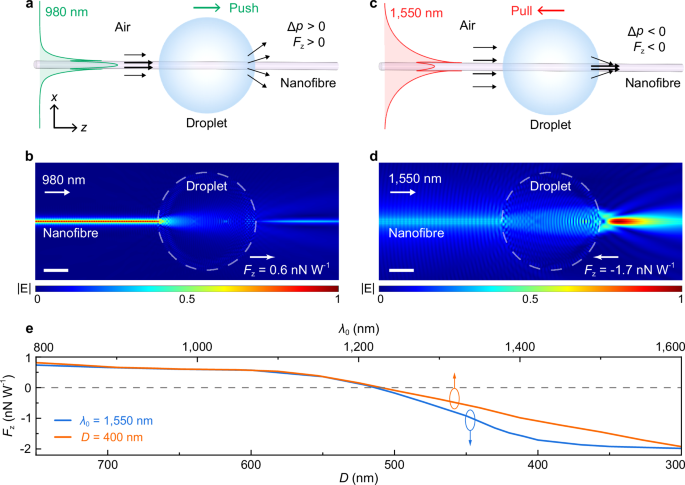
a Schematic of pushing a droplet along a silica nanofibre by a 980-nm-wavelength light guided along the nanofibre. After penetrating the droplet, the tightly confined driving light (horizontal black arrows) diverges into the far-field (divergent black arrows), resulting in a positive momentum transfer (i.e. Δp > 0) and an optical pushing force (i.e. Fz > 0). b Calculated electric field |E| mapping of the HE11 mode (λ0 = 980 nm) of a 400-nm-diameter silica nanofibre penetrating through a 20-μm-diameter silicone-oil droplet. The grey dashed line indicates the profile of the droplet. Scale bar, 5 μm. c Schematic of pulling a droplet along a silica nanofibre by a 1550-nm-wavelength light guided along the nanofibre. After penetrating the droplet, the loosely confined driving light (horizontal black arrows) is focused into the nanofibre (focused black arrows) in the near-field, resulting in a negative momentum transfer (i.e. Δp < 0) and an optical pulling force (i.e. Fz < 0). d Calculated |E| mapping of the HE11 mode (λ0 = 1550 nm) penetrating through a 20-μm-diameter silicone-oil droplet. Scale bar, 5 μm. e Calculated λ0-dependent Fz with D = 400 nm (orange line) and D-dependent Fz with λ0 = 1550 nm (blue line), respectively.
The optical force can be switched between pushing and pulling types by changing the ratio D/λ0. For reference, Fig. 1e gives the theoretical dependence of optical force Fz exerted on the droplet on D and λ0, respectively. With a constant D of 400 nm, Fz is positive (i.e. a pushing force) when λ0 is relatively small. When λ0 exceeds 1.23 μm, Fz becomes negative (i.e. a pulling force), with its absolute value increasing almost linearly with λ0. Similarly, with a constant λ0 of 1550 nm, the pushing force changes to pulling force when D decreases below ∼520 nm. In silica nanofibres, the critical point of Fz = 0 occurs at D/λ0 ∼ 1/3 (see Supplementary Fig. 2 for droplets of different materials), which can be changed by using other nanofibre material or environmental medium.
To experimentally demonstrate the switch from pushing force to pulling force in an optical nanofibre, we send continuous wave (CW) lights with λ0 = 980 nm and 1552 nm into a horizontally suspended 373-nm-diameter 2-cm-length silica nanofibre for generating pushing and pulling forces, respectively (Fig. 2a, see 'Methods'). Fabricated by a flame-heated taper drawing technique with an ultra-high-precision diameter control system50 (see 'Methods'), the nanofibre has excellent surface smoothness and diameter uniformity, featuring an overall optical transmittance higher than 95% around 1550-nm wavelength (Supplementary Fig. 3). After loading a 20-μm-diameter silicone-oil droplet on the nanofibre via micromanipulation (see 'Methods' and Supplementary Fig. 4), the optical transmittance of the nanofibre is reduced to 36%. As shown in Fig. 2b and Supplementary Movie 1, when a 980-nm-wavelength 0.1-W-power light is sent into the nanofibre (with Fz = 0.06 nN, see Supplementary Fig. 5 for the actual intensity distribution), the droplet can be pushed forward with a constant velocity of 6.0 μm s−1, similar to conventional responses reported before47,48,49. When we switch the driving light to a 1552-nm-wavelength 0.05-W-power light (Fz = −0.09 nN, see Supplementary Fig. 5), the droplet can be pulled back with a constant velocity of −4.3 μm s−1 (Fig. 2c and Supplementary Movie 1, with an accelerating time for reaching 99% of the constant velocity around 1 μs, as shown in Supplementary Note 2), clearly confirming the possibility of generating optical pulling force in a nanofibre with a small D/λ0 (Fig. 1e). The experimentally observed motion behaviour of the droplet agrees well with our theoretical calculation results (Fig. 1b, d), and confirms the Minkowski-type photon momentum in the mixed background51.
Fig. 2: Optical pushing and pulling of a droplet with a same nanofibre.
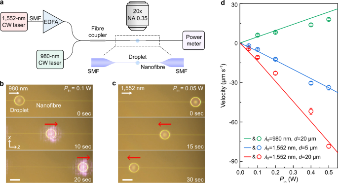
a Schematic of the experimental setup. EDFA, erbium-doped optical fibre amplifier. Top-view time-sequential optical microscope images of forward (b) and backward (c) motions of a 20-μm-diameter silicone-oil droplet along a 373-nm-diameter silica nanofibre. The power of the driving light (Pin) is 0.1 W for the 980-nm-wavelength light in (b) and 0.05 W for the 1552-nm-wavelength light in (c), respectively. Note that in (b), the 980-nm-wavelength light is scattered by the droplet and observed by the CCD camera in the far-field. Scale bars, 20 μm (b, c). d Measured droplet velocity (hollow circles) with different Pin, λ0 and droplet diameters d, showing good consistency with the calculated results (solid lines). The error bars denote standard deviations of the measured velocity.
It’s worth mentioning that, in our theoretical calculation, we assume that the droplet has a spherical shape. Although the measured eccentricity e of the droplet is dependent on droplet diameter and nanofiber diameter, and is typically nonzero (i.e. the droplet is ellipsoidal to a certain degree, see Supplementary Fig. 4), for most of the droplets used in this work with relatively small eccentricity (e.g. e < 0.3), the deviation of Fz from the spherical shape is very small (Supplementary Fig. 6), thus the droplet shape can be approximated as spherical in this work. In addition, even with a smaller droplet (e.g. 5 μm in diameter, blue circles in Fig. 2d), in which less photon momentum is transferred from the air to nanofibre (Supplementary Fig. 7), we still observe the pulling effect of the droplet under a relatively low (e.g. 0.1 W) optical power Pin. Since the optical forces exerted on a droplet are power-dependent, increasing Pin of the guided light in a nanofibre yields a higher droplet velocity in both optical pushing and pulling (hollow circles in Fig. 2d). To intuitively describe the droplet motion, we establish a kinematic model of the droplet motion along a horizontal nanofibre and obtain the relationship between Fz and the droplet velocity (Supplementary Note 2), as solid lines plotted in Fig. 2d. When Pin = 0.5 W, the droplet (20 μm in diameter) can be pulled by a 1552-nm-wavelength light with a measured velocity of −78 μm s−1, which agrees well with the calculated velocity (−75 μm s−1). It’s remarkable that further increasing the Pin of the 1552-nm-wavelength light to 3 W can significantly increase the droplet velocity to −2.8 mm s−1 (Supplementary Movie 2), which is 2 orders of magnitude faster than that with free-space plane-wave illumination reported previously21. In addition, we also realise optical pulling of a droplet in a 300-Pa vacuum environment (Supplementary Fig. 8 and Supplementary Movie 3), which excludes other effects such as the photothermal-induced photophoretic force36,37,38,39,40. To quantitatively evaluate the photothermal effect on the droplet motion, we measure the optical absorption coefficient α of the employed silicone oil and investigate the temperature distribution of the droplet based on a thermal dissipation simulation model (Supplementary Fig. 9). When the droplet is pulled by two beams of lights with evidently different absorption coefficients (α1 = 0.43 cm−1 at λ1 = 1535 nm and α2 = 0.19 cm−1 at λ2 = 1570 nm), the measured velocity is almost the same (see Supplementary Fig. 10 and Supplementary Movie 4), which rules out the photothermal Marangoni effect on the droplets and further confirms that the pulling force originates from the photon-momentum transfer. Besides the liquid droplet, solid particles can also be optically pulled when they are loaded into a droplet carrier. For example, by embedding a 3-μm-diameter polystyrene particle into an 18-μm-diameter droplet, the droplet mixture can be pulled similarly to the pure droplet (see Supplementary Fig. 11 and Supplementary Movie 5).
Ultra-long-range optical pulling of a droplet along a nanofibre
Since its waveguiding mode can be regarded as a low-loss non-diffraction Bessel beam, a nanofibre with enough length may be able to support ultra-long-range optical pulling. To show this, we fabricate a 40-cm-length 325-nm-diameter silica nanofibre that is connected to standard fibres (i.e. the fibre preform of the nanofibre) with biconical tapers at both sides (see Supplementary Fig. 12 for the diameter distribution), and transfer a silicone-oil droplet (45 μm in diameter) onto one side of the nanofibre (Fig. 3a, see also Supplementary Fig. 13 for the experimental setup). When the Pin of the driving light is increased to exceed ~0.1 W, the droplet is starting to be pulled by the light, with a velocity increasing with Pin. Using a 1.0-W-power light, the droplet can be pulled from one side to the other in ~1.5 h without observable thermal deformation or damage (Supplementary Fig. 14), with a total pulling range of ~40 cm and an average velocity of −75 μm s−1 (Fig. 3b and Supplementary Movie 6). Such an optical pulling range is about 3 times larger than the theoretically predicted longest single-beam pulling distance25 (e.g. 14 cm) and comparable to that achieved by photophoretic force on light-absorbing objects36,38,40. It’s also worth mentioning that, when a droplet is pulled along a nanofibre with a nonnegligible tapering profile (Supplementary Fig. 15 and Supplementary Movie 7), the velocity of the droplet decreases monotonically with increasing fibre diameter, and finally the droplet stops at a critical point with D/λ0 ~ 1/3 (Fig. 3c, marked by a red circle), agreeing well with the theoretical calculation result in Fig. 1e.
Fig. 3: Ultra-long-range optical pulling of a droplet along a long nanofibre.
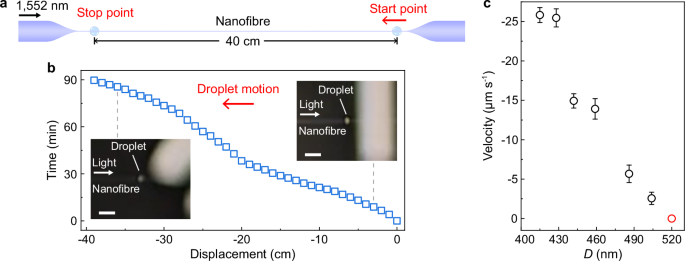
a Schematic of the pulling range. b Measured time trajectory of a 45-μm-diameter silicone-oil droplet pulled along a 40-cm-long silica nanofibre by a 1.0-W-power 1552-nm-wavelength CW light. Insets, typical side-view photographs of the droplet around the right and left ends of the nanofibre, respectively. Scale bars, 300 μm. c Measured velocity of a 10-μm-diameter droplet pulled along a nanofibre (with increasing diameter) by a 0.2-W-power 1552-nm-wavelength CW light. The error bars denote standard deviations of the velocity.
Vertical pulling of a droplet against its gravity
Owing to its high flexibility and precision, vertical optical levitation or manipulation of objects has attracted extensive research interest from biological science, precision metrology to fluid dynamics1,2,3,4,5,32,33,34,35. To this end, a beam of light is usually focused to trap and manipulate freestanding objects by changing the focus position of the light, which requires motion stages for light beam alignment. Here, by using a motionless nanofibre with D/λ0 < 1/3, we show that micro-scale droplets can be vertically levitated and pulled up by the optical force. As schematically illustrated in Fig. 4a, when a 1552-nm-wavelength light is sent into and guided along a nanofibre from top to bottom, a droplet attached onto the nanofibre can be manipulated to go up, down or suspended by changing the Pin of the driving light (see also Supplementary Fig. 16 for the experimental setup). As shown in Fig. 4b, without the driving light, the droplet (65-μm diameter, ~170 times larger than the nanofibre diameter) slides down along the nanofibre (D = 373 nm) by gravity (~1 nN), with a velocity of 6 μm s−1 (blue region in Fig. 4c, see also Supplementary Movie 8). When the driving light is turned on with Pin = 0.1 W, the droplet instantly stops descending and keeps motionless (yellow region in Fig. 4c). When the Pin is increased to 0.5 W, the optical pulling force (Fz = −1.15 nN, see Supplementary Fig. 17) is large enough to pull the droplet upwards, with a velocity of −13 μm s−1 (red region in Fig. 4c). The experimentally observed surface scattering of the HE11 mode (IV and VI in Fig. 4b) shows good agreement with the simulation result (Supplementary Fig. 17). With a single nanofibre, it is also possible to manipulated multi-droplets. For example, using a 385-nm-diameter nanofibre, we manipulate two droplets (60 μm and 35 μm in diameters of droplet 1 and droplet 2, respectively) in succession, as shown in Fig. 4d. Without the driving light (I and II in Fig. 4d), the droplet 1 slides down by gravity and approaches the motionless droplet 2 (balanced via viscous force and gravity). When the distance between two droplets is reduced to ~15 μm, we turn on the light (Pin = 0.5 W) and observe that droplet 1 is pulled up instantly with a velocity of −110 μm s−1 while droplet 2 is pushed down by the focused field (III in Fig. 4d and red region in Fig. 4e, see also Supplementary Movie 9). When the separation increases to ~100 μm, the focused field (by droplet 1) has much less effect on the droplet 2, and the droplet 2 is then pulled up by the remaining waveguiding-mode field of the nanofibre with a velocity of −32 μm s−1 (IV in Fig. 4d and red region in Fig. 4e).
Fig. 4: Vertical pulling of droplets along a nanofibre.
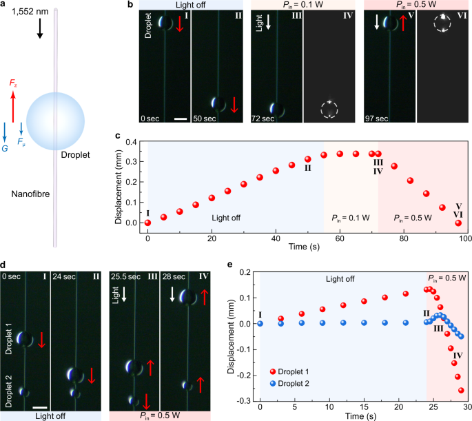
a Schematic of vertical pulling of a droplet by a 1552-nm-wavelength light guided downward along an upright nanofibre. When Fz is larger than the sum of the gravity G and the viscous resistance force Fμ of the droplet, the droplet can be pulled to move upward along the nanofibre. b Side-view sequences of optical microscopy images of a 65-μm-diameter droplet pulled up by the 1552-nm-wavelength light along a 373-nm-diameter nanofibre. Without the driving light (I and II), the droplet slides down by its gravity. When the driving light is turned on with Pin = 0.1 W (III and IV), the droplet stops descending and keeps motionless. With Pin increasing to 0.5 W (V and VI), the droplet is pulled up along the nanofibre. Surface scattering images of the HE11 mode in III and V are given in IV and VI, respectively. Scale bar, 50 μm. c Measured displacement of the droplet at different time. d Sequencing optical microscopy images showing vertical pulling of two droplets along a 385-nm-diameter nanofibre. The diameters of droplet 1 and droplet 2 are 60 μm and 35 μm, respectively. Without the driving light (I and II), the droplet 1 slides down by gravity and approaches the motionless droplet 2. When the distance between two droplets is reduced to ~15 μm, the driving light is turned on with Pin = 0.5 W. The droplet 1 is pulled up instantly while droplet 2 is pushed down by the focused field (III). When the separation increases to ~100 μm, the droplet 2 is pulled up by the remaining waveguiding-mode field of the nanofibre (IV). Scale bar, 50 μm. e Measured displacements of droplet 1 and droplet 2 at different time.
Discussion
In summary, based on the Minkowski-photon-momentum engineering of the waveguiding mode of a silica nanofibre, we have realised a highly efficient optical pulling with ultra-long working distance (up to 40 cm) and large speed (up to −2.8 mm s−1), which are much longer and faster than other photon-momentum-based pulling approaches reported before. Meanwhile, the fibre-based alignment-free configuration and the possibility of switching between pulling and pushing forces by the wavelength of the driving light, as well as the vertical manipulation of single and multiple droplets, may offer more flexibility for practical applications such as liquid transport, drug delivery and bioengineering5,32,33,34,35,52. Also, as the driving light guided along the nanofibre can be flexibly redirected by bending the fibre48, the fibre-based optical pulling and pushing forces can be readily designed for multi-dimensional optical manipulation. Moreover, as the waveguiding loss of a sub-wavelength-diameter silica nanofibre can go down to 0.03 dB m−1 (see ref. 53), more than two orders of magnitude lower than all other sub-wavelength-width optical waveguide48, it is feasible in principle to further extend the pulling range (e.g. >10 m) by using a nanofibre with a larger length. In addition, although our approach is currently only valid for droplets, solid particles can be loaded into the droplet and optically pulled along the nanofibre. Overall, our results pave the way for ultra-long-range optical pulling of transparent objects by direct photon-momentum transfer, which may find applications from nanophotonics, optomechanics to biophotonics and optofluidics.
Methods
Numerical simulation and calculation of the optical force
As a kind of quasi one-dimensional optical waveguides, silica nanofibres with sub-wavelength diameters are typically operated in single mode (i.e. HE11 mode). The fibre-guided light field assumed in the theoretical calculation and used in the experiments is quasi-linearly polarised. The components of electric and magnetic field (E and H) of the HE11 mode in optical nanofibres are calculated by using finite-difference time-domain (FDTD) simulation (see Supplementary Fig. 18 and Supplementary Note 1). The refractive indices of the silica nanofibre and the silicone-oil droplet are set to be 1.450 and 1.406 at 980-nm wavelength, and 1.444 and 1.404 at 1552-nm wavelength. To quantitatively calculate the optical force exerted on the droplet, we perform an integration of the time-averaged Minkowski stress tensor <TM> over a closed surface S surrounding the droplet35:

with TM = DE + BH − (B ? H + D ? E)I/2, where nS is a normal vector pointing in the outward direction from the surface S, D and B are the electric displacement vector and magnetic flux density, I is the unit tensor.
Experiments of the nanofibre-based optomechanical manipulation and characterisation
The pulling light comes from a 1552-nm-wavelength CW fibre laser (SPL Photonics, DBL-1550 nm-10 mW), after being amplified by an erbium-doped optical fibre amplifier (EDFA, Connet, MFAS-Er-C-B-15). The pushing light comes from a 980-nm-wavelength CW laser diode (II-VI, LC962UF74P-20R). The total optical loss of coupling light from the source to the nanofibre is lower than 1 dB. Light output of the fibre is measured by a thermopile power metre (Newport, PMKIT-22-01). The motion of the droplet is captured and real-time recorded by a charge-coupled device camera (CCD, Nikon, DS-fi1c).
Fabrication of nanofibre-based optomechanical structures
High-quality silica nanofibres are fabricated by flame-heated taper drawing of standard single-mode fibres (Corning, SMF-28e+) with a flame-brush process in a Class 1000 cleanroom. During the fabrication, the standard optical fibre is heated by a stable oxyhydrogen flame and pulled smoothly by high-precision travelling stages on both sides, incorporated with an ultra-high-precision diameter control system50. The pulling process is terminated until the fibre diameter is reduced to the target diameter. Generally, an optical nanofibre obtained in this way is connected to standard fibres via adiabatic tapers at both ends, enabling an adiabatic transition of the guided light between the nanofibre and the standard fibres. For ease of handling, a U-shaped bracket is used to detach an as-fabricated nanofibre from the taper-drawing system. The material of silicone-oil droplets is polydimethylsiloxane with a viscosity of 1000 cst (Dow, XiameterTM PMX-200). The silicone-oil droplets can be transferred from a microfibre tip to a suspended silica nanofibre via micromanipulation under an optical microscope (see Supplementary Fig. 4). Due to the surface tension, the on-nanofibre droplet keeps a shape very close to a sphere.
Data availability
Data supporting the findings from this work are available within this article and its Supplementary Information. The data generated in this study are provided in the Source Data file. Source data are provided with this paper.