


Abstract
There is a growing demand for precise health management, capable of differentially caring every inch of skin as an on-body network. For which, each network node executes not only multi-physiological sensing, but also in-situ logic computing to save cloud computing power for massive data analysis. Herein, we present a smart fiber with multilayers of overprinted patterns, composed of many small units with 0.3 mm long to function as a one-dimension (1D) array of chip-like multi-threshold logic-switch circuit. Via soft contact of curved surfaces between fiber and ink-droplet, an overprinting method is developed for stacking different layers of patterns with a line width of 75 μm in a staggered way, enabling batch production of circuit units along one long fiber. A smart fiber with high density of >3000 circuit units per meter can be woven with fiber-type sensors to construct a textile-type body-covering network, where each node serves as a computing terminal.
Introduction
There is a growing demand for lifestyles centered on precise health management1,2,3,4,5,6. Especially, many patients suffering from serious diseases, such as pyemia, sepsis, tetanus, etc.7,8,9,10, should pay attention to small body wound infections, which necessitate even inch-by-inch differentiated monitoring and analysis of a certain body area. Up to now, most existing wearable technologies have handed over data-processing tasks to cloud computing, which demands extensive cloud computing power and serious bandwidth congestion to ensure timely data analysis11,12,13,14,15. Consequently, there is a critical need to develop a body-care network, where each node could function as a complete circuit capable of executing a set of group functions, including not only multiple physiological sensing, but also in-situ logic computing for emergency identification, early warning, and body management16,17,18,19. Unfortunately, circuits with such group functions usually rely on printed circuit boards (PCBs), which are constructed by stacking conductive or semiconductive patterns layer by layer onto a rigid or plastic board in a staggered way, but often sacrifice body wearing comfort20,21,22,23.
In recent years, wearable electronics in the form of fibers and textiles have garnered significant attention, owing to their wearing comfort for covering the entire human body. These fiber devices, with different capabilities including power generation24,25,26,27, energy storage28,29,30,31, sensing32,33,34,35, etc., have been fabricated by the concentric assembly of different functional layers onto fibers. There are currently two typical strategies for further integration as textile-type circuits: one is to interweave multiple fiber devices into a textile as an integrated circuit36,37, and the other is to directly overprint patterns on textiles38,39. However, both strategies confront challenges of high component density for building circuits within every inch of skin for differential caring. A game-changing solution is to assemble many small circuit units on a single thin fiber, where each unit consists of multiple microdevice components connected as one complete circuit.
Notably, the most critical and representative circuit for health management is the logic switch circuit to recognize abnormal situations exceeding predefined thresholds, whose implementation relies not just on simple binary switching operations (0 or 1)40,41,42,43,44, but also involves multiple critical thresholds, necessitating segmented, sequential, or parallel switching operations45,46,47,48. While such a logic switch circuit with multiple thresholds usually requires integrated circuit (IC) chips rather than simple device components.
Herein, we present smart fibers composed of many small units, which function as a 1D array of chip-like multi-threshold logic switch circuits. The smart fiber integrates many segmented portions of modular circuits as fundamental units. Each modular circuit unit, as small as 0.3 mm in length, composed of resistors and transistors, can emulate the operational capabilities of multi-channel logic switch chips. A scalable multilayer overprinting method was developed for batch production of circuit units along one long fiber, to reach a density of >3000 per meter. A textile network is formed by weaving such fibers together with fiber-type sensors. In this case, each textile node demonstrates the capability of in-situ multi-threshold logic-switch computing, to perform either remote indoor environment control or outdoor on-body health management, without handing over sensing data to cloud computing. Such a textile as an on-body network can save massive cloud computing power, by making each wearer a computing terminal for building a shared computing cluster across a human community.
Results
Structural design of the chip-like multi-threshold logic switch fiber
As illustrated in Fig. 1a, a long fiber composed of many small circuit units, down to even 0.3 mm in length, was fabricated, which functions as a 1D array of chip-like multi-threshold logic switch circuits. In such a fiber, each unit is equivalent to a circuit composed of multiple device components, including resistors and transistors. As shown in Fig. 1b, c, any fiber section taken from the smart fiber, containing several circuit units, can function similarly to a multi-channel logic switch chip (see details in Supplementary Table 1).
Fig. 1: Structural design of smart fibers to function as a 1D array of chip-like multi-threshold logic switch circuits.
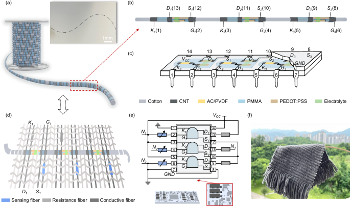
a A smart fiber with many units of logic switch circuit (Inset: photograph of a long fiber). b Schematic diagram of a fiber section taken from the smart fiber containing multiple circuit units (Terminal K: Connecting to one end of the resistor in the circuit unit for gate-control voltage input of the transistor, of which the resistor is utilized to match the current from gate electrode to source electrode of the transistor; Terminal D: Connecting to the drain electrode of the transistor in the circuit unit; Terminal S: Connecting to the source electrode of the transistor in the circuit unit; Terminal G: Connecting to the gate electrode of the transistor in the circuit unit). c Conceptual diagram of the developed smart fiber being functionally equivalent to a traditional PCB-based multi-threshold logic switch circuit chip (VCC: Volt current condenser; GND: Ground). d Schematic diagram of a textile-type multi-threshold logic switch circuit, woven with the smart fiber with multiple circuit units. e Working principle and peripheral component connection of the textile-type multi-threshold logic switch circuit (N1, N2: Circuit nodes). f Photograph of a textile-type multi-threshold logic switch circuit.
As shown in Fig. 1d, such a fiber section can then be interwoven into one textile together with other peripheral device components, including sensors, resistors, etc., to construct a textile-type circuit for realizing not only multiple physiological sensing, but also in-situ multi-threshold logic computing (see detailed fabrication of fiber-type devices in Supplementary Note 1 and Supplementary Figs. 1–6).
The circuit design for the textile is shown in Fig. 1e and Supplementary Fig. 7. Specifically, each fiber circuit unit can act as a logic switch circuit module in a multi-channel chip. When connected to a sensor with its gate electrode, it is capable of executing a separate single-threshold logic switch operation in response to sensor signals. Furthermore, with more than one circuit unit in a fiber section, it can be connected to a peripheral circuit to realize different logic relationships between circuit units. In this way, a multi-threshold logic switch circuit with a common-looking textile appearance can be fabricated, as shown in Fig. 1f.
For example, a textile-type triple-threshold logic switch circuit can be constructed by weaving a fiber section composed of three circuit units from the smart fiber into the textile. In this configuration, two fiber circuit units are connected in an “OR” relationship, which is then connected in an “AND” relationship with a third fiber circuit unit (Supplementary Figs. 8, 9). This configuration can be extended to accommodate additional threshold levels (A typical quad-threshold logic switch circuit was designed and provided with its performance data in Supplementary Figs. 10, 11). In other words, such smart fiber functions section-by-section, analogous to an array of chips on a printed circuit board.
Principle of the overprinting fabrication
As depicted in Fig. 2a, the smart fiber can be fabricated from any type of polymer fiber in a roll-to-roll way, by sequentially overprinting five staggered layers of periodic functional patterns, including: (1) Alternating carbon nanotube (CNT) and activated carbon/polyvinylidene fluoride (AC/PVDF) patterns with circular structures, serving as the resistor unit; (2) Asymmetrical polymethyl methacrylate (PMMA) patterns with a blank window, serving as an insulating layer; (3) Parallel up-and-down poly(3,4-ethylenedioxythiophene):poly(styrenesulfonate) (PEDOT:PSS) patterns, acting as the organic semiconductor layer; (4) Segmented circular electrolyte patterns; and (5) Segmented circular CNT patterns, serving as the conductive electrode layer. For these patterns, we employ three types of coating methods, including: the unilateral coating method for PMMA patterns (I), the bilateral coating method for PEDOT:PSS patterns (II), and the full-coating method for AC/PVDF, electrolyte and CNT patterns (III). After multiple layers of patterns are sequentially overprinted in a staggered way, many circuit units are formed simultaneously along one long fiber, and the whole fabrication process is low-cost, scalable and continuous.
Fig. 2: Scalable fabrication of a smart fiber with many circuit units via the overprinting method.
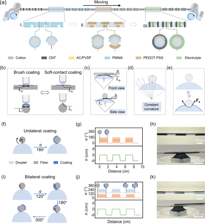
a The overprinting fabrication process for multiple functional layers on a long fiber. b The difference between brush coating and soft-contact coating (Lr: Radial machining accuracy; La: Axial machining accuracy). c–e The principle of soft contact of curved surfaces between fiber and ink droplet to achieve high accuracy (h: The height of droplet movement; Fs: Surface tension). f, g Contacting status during unilateral coating, and its relationship between distance, droplet height, and fiber rotation angle (α: Rotation angle of fiber). h Photograph of the fiber during unilateral coating. i, j Contacting status during bilateral coating, and its relationship between distance, droplet height, and fiber rotation angle (The dashed line denotes the coating layer on the reverse side for bilateral coating). k Photograph of the fiber during bilateral coating.
In fact, for the fabrication of functional layers on fiber surfaces, brush coating is commonly used, which relies on fixed hard contact between the flat contacting surface of the bristle head and the fiber surface. However, the contact area is limited by the size of the brush head, which restricts its coating accuracy. Differently, our coating method is based on adaptive soft contact between the curved surfaces of ink-droplets and fiber, which endows it with a small contact area, adaptive axial symmetry, and reversible contacting status (Fig. 2b).
On one hand, the contact area between the curved surfaces of the ink droplet and fiber is significantly small, even smaller than the diameter of the droplet. For example, an increase in droplet height of 10 µm results in an axial coating width of 0.1 mm and a radial coating width of 75 µm (see details in Fig. 2c, Supplementary Note 2, and Supplementary Figs. 12, 13). Thus, a density of over 3000 circuit units per meter along the long fiber was achieved, which is more than four times the component density of printed circuit textiles (Supplementary Note 3).
On the other hand, benefiting from the axial symmetry and controllable surface tension of the curved ink-droplet surface, the contact status in the coating process not only adapts to fiber vibration and alignment mismatch coming from different directions but also keeps stable throughout the entire process along a long fiber. As indicated in Fig. 2d, when the fiber hits the droplet from different directions, the contact area remains consistent. As indicated in Fig. 2e, the surface tension of droplets can be well controlled by pressure in a thin pipe, which allows the droplet to undergo a certain degree of reversible deformation to adapt to any curvature of the fiber. In other words, it can ensure a timely supply of droplets to maintain continuous fabrication.
Actually, three different coating methods, including unilateral coating, bilateral coating, and full coating, can realize very precise pattern control by dynamically adjusting the height of the ink-droplet and the rotation angle of the fiber as the droplet moves (Supplementary Fig. 14).
Firstly, full coating is achieved when the droplet completely envelops the fiber, while the fiber rotates consistently in one direction. In this case, segmented periodic full coating can be realized by adjusting the height and movement of the droplets (see details in Supplementary Note 4, Supplementary Figs. 15–17, and Supplementary Movie 1).
Secondly, unilateral coating occurs when the droplet makes tangential contact with the fiber surface, while the fiber rotates at an arbitrary angle, such as 180 degrees, as shown in Fig. 2f, g. In this case, the height and movement of the droplets follow a square-wave relationship, and the angle of fiber rotation and movement of the droplets follow a triangular-wave relationship, to realize segmented periodic unilateral coating. Moreover, the unilateral coating can also be realized by adjusting the immersion height of the droplet and the fiber. A photo of unilateral coating is presented in Fig. 2h, where the radial machining accuracy can reach 75 μm (see details in Supplementary Note 4, Supplementary Figs. 18, 19, and Supplementary Movie 2).
Thirdly, bilateral coating is achieved by allowing the droplet to make tangential contact with the fiber surface, while the fiber rotates at a smaller angle, such as 120 degrees, as depicted in Fig. 2i, j. In this case, the height and movement of the droplets follow a square-wave relationship, and the angle of fiber rotation and movement of the droplets follow a triangular-wave relationship with a lower peak value, to realize segmented bilateral coating. Moreover, the bilateral coating can also be realized by adjusting the immersion height of the droplet and the fiber. A photo of bilateral coating is presented in Fig. 2k, where the radial machining accuracy can reach 75 μm (see details in Supplementary Note 4, Supplementary Figs. 20, 21, and Supplementary Movie 3).
Performance of one typical circuit unit
As shown in Fig. 3a, one typical unit taken from the smart fiber is presented, which is equivalent to a logic-switch circuit composed of a transistor and a resistor. In addition, more types of circuit units can be fabricated in a similar way via our overprinting methods, by substituting alternative conductive or semiconductive materials for device components in the circuit unit or modifying the types of device components.
Fig. 3: Structure optimization of the fiber circuit unit.
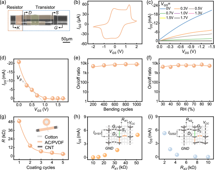
a A photo of one fiber circuit unit composed of a resistor and a transistor. b Cyclic voltammetry (CV) curve between the gate and source of a transistor in the fiber circuit unit (IGS: Current from the gate and source of the transistor; VGS: Voltage between the gate and source of the transistor; Working electrode (WE): Gate electrode of the transistor; Reference electrode (RE) and counter electrode (CE): Source electrode of the transistor; Voltage scan range: −2 to +2 V; Scan rate: 100 mV/s). c Electrical characteristics of the transistor (IDS: Current from the drain and source of the transistor; VDS: Voltage between the drain and source of the transistor). d Transmission characteristics of the transistor (Vp: pinch-off voltage; Fixed VDS = −1.5 V). e On/off ratio of the transistor under different bending cycles (On/off ratio measured under VDS = −1.5 V; Bending radius: 6 mm; Corresponding bending angle: 60°). f On/off ratio of the transistor under different relative humidity (RH%; On/off ratio measured under VDS = −1.5 V). g Performance of the fiber-type resistor for different coating cycles. h, i Characteristics of the fiber circuit unit when connected in two types of logic switch circuit (Inset: the corresponding testing circuit connection for the fiber circuit unit; RX1, RX2: adjustable resistors).
For the transistor, it is formed by assembling two parallel up-and-down PEDOT:PSS layers and a circular electrolyte layer onto a single fiber (see details in Supplementary Note 5 and Supplementary Figs. 22–34). As shown in Fig. 3b, the working principle of the transistor unit relies on the redox reaction of PEDOT: PSS. Specifically, when a positive voltage is applied to the gate, Na+ from the electrolyte penetrates the PEDOT:PSS to form a non-conductive reduced state, which increases the resistance of PEDOT:PSS and decreases the channel current. Upon removal of the voltage, Na+ migrates back into the electrolyte to restore the oxidized state. The electrical characteristics of the transistor are depicted in Fig. 3c, d, showing the typical traits of a depletion-type transistor. As the gate voltage gradually increases from 0 to 1.5 V, the conductivity of the fiber-type transistor decreases by over 2500 times, with a pinch-off voltage of ~0.9 V.
As depicted in Fig. 3e and Supplementary Fig. 35, the fiber-type transistor exhibits enhanced robustness in on/off performance during bending, attributed to the significantly longer carrier transfer distance of Na+ compared to that in traditional semiconductor transistors. Additionally, as shown in Fig. 3f, effective encapsulation ensures that the transistor remains unaffected by environmental conditions, such as different levels of humidity.
For the resistor, the structure and the resistance responses of an optimized fiber-type resistor are shown in Fig. 3g, which was assembled by an AC/PVDF layer on the cotton wire between two coaxially coated sections of CNT layers. The resistance of the fiber-type resistor decreases with an increasing number of coatings and can also be adjusted by varying the amounts of AC or PVDF, as well as the coating length (Supplementary Fig. 36).
To verify the logic switch capability of one typical circuit unit taken from the smart fiber, two types of logic switch circuits were fabricated. One employs a resistor connected to the gate of the transistor in the circuit unit and volt current condenser (VCC) as the signal source, while the other employs a resistor connected to the gate of another transistor in the circuit unit and ground (GND) as the signal source, as shown in Fig. 3h, i. For the first type of logic switch circuit (Fig. 3h and Supplementary Fig. 37a, b), an increase in the resistance of RX1 causes VG1 to decrease, thereby increasing ID1S1. This allows the circuit to judge whether the situation is beyond the upper limit of the predefined threshold range. For the second type of logic switch circuit (Fig. 3i and Supplementary Fig. 37c, d), an increase in the resistance of RX2 reduces VG2, leading to a decrease in ID2S2. This enables the circuit to judge whether the situation is below the lower limit of the threshold range. Thus, the first type of logic switch circuit can function as an upper limit comparator, while the second type of logic switch circuit can function as a lower limit comparator. Notably, small current values are defined as the “ON” state, encoded as 0, while large current values are defined as the “OFF” state, encoded as 1 (Supplementary Fig. 38). In this way, our strategy enables one circuit unit to perform separate single-threshold logic switch computing.
Performance of a textile-type dual-threshold logic switch circuit
As previously discussed, each circuit unit in the smart fiber has been proven to function as an independent single-threshold logic switch circuit. Moreover, more circuit units can be further connected with certain logical relationships, which enables the construction of a fiber- or textile-type logic switch circuit with more thresholds.
To verify this, a textile-type dual-threshold logic switch circuit was fabricated by weaving one fiber section taken from the smart fiber, containing two different circuit units, together with fiber-based humidity sensors into one textile, as shown in Fig. 4a and Supplementary Fig. 39. In this case, one fiber circuit unit is designed to determine whether the humidity exceeds the upper threshold, while the other identifies whether the humidity falls below the lower threshold. These two circuit units are connected through an “OR” logic relationship.
Fig. 4: Performance of a textile-type dual-threshold logic switch circuit, formed by interweaving fiber-type humidity sensors together with one fiber section composed of two circuit units.
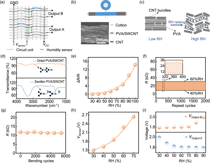
a Schematic diagram of the textile-type dual-threshold logic switch circuit. b Structure of the fiber-type humidity sensor. (Inset: SEM image of PVA/SWCNT layer). c Working principle of the fiber-type humidity sensor. d FTIR spectra of the PVA/SWCNT layer under dry and swollen conditions. e Performance of the fiber-type humidity sensor under different humidity (RH%). f Repeatability of the fiber-type humidity sensor. g Resistance of fiber-type humidity sensor under different bending times. h, i Characteristics of the textile-type dual-threshold logic switch circuit under different humidity.
For the fiber-type humidity sensor, the structure of an optimized fiber-type humidity sensor is shown in Fig. 4b, which was assembled by depositing a poly(vinyl alcohol) /single-walled carbon nanotubes (PVA/SWCNTs) layer on a cotton wire between two coaxially coated sections of CNT. As depicted in Fig. 4c, the working principle relies on the conductivity and strength of the SWCNTs. With an increase in humidity, the expansion of PVA molecules results in a widening of the distance between the SWCNTs, leading to higher resistance. As shown in Fig. 4d, to evaluate the recovery of interconnections within the PVA/SWCNTs layer during hygroscopic and dehumidifying, Fourier transform infrared spectroscopy (FTIR) was used for analysis, which proved a change in the resistance of the PVA/SWCNTs layer upon wetting and drying state.
Figure 4e shows the relationship between sensor response and different humidity levels, indicating that an increase in humidity results in an increase in sensor resistance. As shown in Fig. 4f, the fiber-type humidity sensor demonstrated long-term stability across alternating humidity levels of 40 and 60%. Furthermore, as shown in Fig. 4g and Supplementary Fig. 40, the stability of the fiber-type humidity sensor under different bending conditions was tested, which revealed that the sensor has robust flexibility.
As shown in Fig. 4h, i, the characteristics of the textile-type dual-threshold logic switch circuit were tested. Figure 4h shows that Vsensor is positively correlated with humidity changes. By adjusting the resistances of the resistors in the fiber section containing two circuit units, the humidity threshold was set within the range of 40 to 70%, in accordance with the humidity range for both sub-healthy and healthy humans. The voltages of Output A and Output B under different humidity levels, covering 40 to 70% (Fig. 4i), were tested, which revealed that the voltage of Output B increases when humidity exceeds 70%, while the voltage of Output A rises when humidity drops below 40%. These confirm that the textile-type dual-threshold logic switch circuit formed by fiber-type humidity sensors and one dual-circuit-unit fiber section can effectively differentiate and respond to conditions beyond preset thresholds.
It is noteworthy that, any fiber section, containing more circuit units, can effectively operate as a multi-channel logic switching chip, enabling the construction of complex multi-threshold logic circuits. These circuit units can be connected via peripheral circuits to realize more advanced logical connection relationships, such as “XOR”, “NAND”, “NOR”, etc. In this way, logic switch computing with more thresholds or even higher-level computation capabilities can be further constructed.
Function demonstration of the textile-type multi-threshold logic switch circuit
For the function demonstration, one fiber section containing several circuit modules was woven into one textile together with fiber-type sensors. Of which, one circuit unit was connected to a Wi-Fi chip to function as a remote control, which has demonstrated the capability of wireless control of surrounding electrical appliances, akin to PCB-based remote-control circuits. The other circuit unit was paired with other functional textiles to achieve an integration of sensing, judgment, and control, which has demonstrated the potential to realize an all-fiber on-body health management system.
In the first representative application for indoor environment condition control, the circuit connection of the textile-type logic switch with a Wi-Fi chip is shown in Fig. 5a, b and Supplementary Fig. 41. This configuration enables simultaneous control of one humidifier and one air-conditioner. As shown in Fig. 5c, d, when worn on the human body, the textile activates a dehumidifier and deactivates a humidifier when indoor humidity exceeds 70%. Conversely, it activates a humidifier and deactivates a dehumidifier when indoor humidity drops below 40% (Supplementary Movie 4). Such a textile can integrate with a Wi-Fi chip to function comparably to a PCB-based remote-control circuit.
Fig. 5: Function demonstration of the textile-type multi-threshold logic switch circuit composed of a fiber section with multiple circuit units.
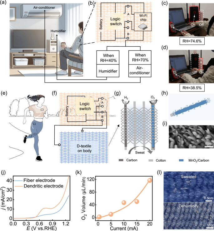
a Schematic diagram of indoor environment condition control application for the textile-type multi-threshold logic switch circuit. b The circuit connection of the textile-type multi-threshold logic switch with a wireless chip for controlling one humidifier and one air-conditioner simultaneously. c The logic switch circuit textile worn on the human body turns on a dehumidifier and turns off a humidifier when indoor humidity exceeds 70%. d The logic switch circuit textile worn on the human body turns on a humidifier and turns off a dehumidifier when indoor humidity falls below 40%. e Schematic diagram of outdoor on-body humidity control application for the textile-type multi-threshold logic switch circuit. f The circuit connection of the textile-type multi-threshold logic switch with an electrochemical dehumidifier textile (D-textile) for on-body humidity control. g Structure and working principle of the D-textile with an area of 8.4 cm2. h Structure of the MnO2/Carbon fiber anode in the D-textile. i SEM image of the dendritic MnO2 on the fiber anode. j Performance of the MnO2/Carbon fiber anode with different MnO2. k Oxygen generation of the D-textile at a current density of 3 A/cm2. l Photograph of a sweated textile before and after the textile-type multi-threshold logic switch activates the D-textile.
As a matter of fact, sweating varies across different body areas during exercise, requiring precise and localized humidity management. In a second application for outdoor on-body humidity control (Fig. 5e, f), a textile logic switch circuit paired with an electrochemical dehumidifier textile (D-textile)49. Upon detecting sweat, the logic circuit activates by the voltage from output B of the D-textile for direct sweat removal.
For the D-textile, the structure and working principle are depicted in Fig. 5g (see details in Supplementary Note 6 and Supplementary Figs. 42–50). It is fabricated by weaving fiber manganese dioxide (MnO2) electrodes as the anode and fiber carbon electrodes as the cathode. Upon detecting sweat, the textile logic switch activates the D-textile, initiating oxidation at the anode to generate oxygen and reduction at the cathode to produce hydrogen. As shown in Fig. 5h, i, to enhance oxygen production, a large-area dendritic structure was designed for the MnO2 electrode, which improves the catalytic activity for the oxygen evolution reaction with a performance 1.6 times greater than that of standard MnO2 electrodes (Fig. 5j and Supplementary Fig. 51). During 1 h of electrolysis, the D-textile with an area of 8.4 cm2 generates 7.2 mL of oxygen (Fig. 5k). Photos of a sweated textile before and after activation are shown in Fig. 5l. This textile demonstrates the potential for fully fiber-based on-body health management.
Discussion
In this work, the smart fiber composed of multiple circuit units can be woven with fiber-type sensors into a textile to form a body-covering healthcare network. Such a textile network has advantages in small node size and massive bandwidth savings.
For one thing, each node in the textile network is composed of a circuit unit (~0.03 mm²), fiber-type sensors (~0.1 mm2), and fiber-type resistors (~0.03 mm2). Although each node is capable of multi-physiological sensing and in-situ logic computing, it only achieves a total area of ~0.16 mm2.
For another thing, the human skin surface area, spanning up to ~1.5 m2, allows for the construction of a textile-type body-care network comprising ~9.4 × 10⁶ nodes. As each node is capable of in-situ logic computing, the communication time for continuous data analysis can be reduced to less than 1 s, saving ~300 Mbps of bandwidth for data analysis (Supplementary Note 7). In contrast, cloud-based computing for such large data volumes, using Bluetooth (BLE 5.0) with a bandwidth of 1 Mbps, would require ~300 s for similar calculations, rendering it unsuitable for real-time monitoring and emergency alerts. In the future, more bandwidth savings with orders of magnitude can be achieved through narrowing the line width during coating, stacking more layers of functional patterns along the z-direction, etc., and increasing the weaving density of the textile.
Moreover, each node in the textile healthcare network can serve as a separate computing terminal for early diagnosis, acting as a micro-AI health management chip. By further connecting with more logical relationships, nodes in such a network can realize advanced computation capabilities, which may provide the foundation for fiber- or textile-based computers and exhibit significant potential for on-body massive data computation.
Methods
Additional details on the experiments performed in this study are provided in the Supplementary Information.
Experimental setup for the fabrication of a smart fiber
The custom-built experimental setup equipped with multiple stepper motors enables precise control of droplet axial movement, droplet height, and fiber rotation angle. In which, the control resolution is 0.001 mm for both height and movement distance of droplet, and 1° for the fiber rotation angle.
Humidity sensing setup
Humidity sensing experiments were conducted in a temperature and humidity-controlled chamber (Model: HWS-30). The chamber allows precise regulation of relative humidity (RH) ranging from 2 to 90% and temperature from 5 to 60 °C. For all measurements, the temperature was fixed at 25 °C, and RH gradually increased in steps of 10%. The fiber-type humidity sensor was placed inside the chamber and connected to an external electrochemical workstation to enable real-time electrical signal (To simulate 100% RH, the sensor was tested by directly spraying deionized water onto its surface).
Materials
The poly(3,4-ethylenedioxythiophene):poly(styrenesulfonate)-1000 (PEDOT:PSS-1000) was commercially sourced from Xi’an Polymer Light Technology Corp. Poly(vinyl alcohol) (PVA, molecular weight: 146,000–186,000; 99+% hydrolyzed) was procured from Sigma-Aldrich. Other analytical grade reagents, including diethylene glycol, ethylene glycol, sorbitol, sodium perchlorate (NaClO4), single-walled carbon nanotubes (SWCNTs), manganese dioxide (MnO2), et al. were procured from Chengdu Kelong Chemical Reagent Factory.
All chemicals were used as received without further purification.
Fabrication of the fiber-type humidity sensor
Fiber-type humidity sensors were fabricated by coating carbon nanotube (CNT) and poly(vinyl alcohol)/single-walled carbon nanotubes (PVA/SWCNTs) layers onto cotton fibers using a self-designed coating machine. A coaxial coating of conductive CNT was employed to create two conductive terminals, facilitating the extension of both ends of the PVA/SWCNTs layer.
Fabrication of fiber-type transistor unit
For the preparation of a single fiber-type transistor, the fabrication begins by uniformly coating the surface of a cotton fiber with a CNT layer using a full-coating method, forming a conductive substrate for the G pin. Subsequently, a polymethyl methacrylate (PMMA) insulation layer is applied to the cotton/CNT composite fiber via unilateral coating, creating a window structure that partially exposes the underlying CNT conductive layer. This window structure functionally mimics the through-holes in conventional printed circuit boards (PCBs), serving as a contact interface for subsequent electrode connections. Next, two parallel functional material traces-composed of PEDOT:PSS-1000, 10 wt% diethylene glycol (DEG), and 0.5 wt% polyethylene glycol−2000 (PEG-2000)-are deposited on the PMMA insulation layer using a bilateral coating method. The shorter trace covered the window area and formed a contact with the underlying CNT layer, while the longer trace was connected to the CNT layer at both ends as lead electrodes for the drain (D) and source (S). Then, a gel electrolyte layer (8 wt% D-sorbitol, 33 wt% sodium polystyrene sulfonate (PSS), 0.1 M sodium perchlorate (NaClO4), 12 wt% ethylene glycol (EG) and ultrapure water) is fully coated between the two PEDOT:PSS traces to complete the device structure. Finally, a fully coated PMMA encapsulation layer is applied to the entire surface of the transistor.
Fabrication of fiber-type resistor unit
Resistors were produced using a self-designed mobile coating machine, with repeated applications of activated carbon/polyvinylidene fluoride (AC/PVDF) layers onto the cotton thread. To establish two conductive terminals, a coaxial coating of CNT was applied to both ends of the AC/PVDF section.
Fabrication of the dendritic MnO2 electrode
A stainless-steel cathode was shaped into a ring structure with a diameter of 4 cm. A fiber anode with a diameter of 100 µm was meticulously polished and positioned vertically at the cathode’s center. The aqueous electrolyte, consisting of 0.9 M manganese sulfate (MnSO4), was acidified to a pH of 0.2 using 98% sulfuric acid (H2SO4). Subsequently, the electrolyte was introduced to ensure effective contact between the two electrodes. Finally, dendritic manganese dioxide (MnO2) was electrodeposited onto the surface of the fiber anode.
Fabrication of the electrolytic dehumidification textile
A variety of wire electrodes were intricately woven onto a shuttle-flying weaving machine. During this intricate process, the dendritic MnO2 electrode served as the warp threads, while CNT wire occupied distinct sections of the textile as the weft threads. By employing a rational design of the woven texture, both series and parallel connections could be achieved, offering versatility and flexibility.
Characterization
Electrochemical performance measurements were carried out using the CHI600E electrochemical workstation from Shanghai Chenhua. Morphological analysis was conducted using a scanning electron microscope (S-4800, Hitachi Ltd.). The infrared spectra of PVA/SWCNTs under water absorption and drying conditions were investigated using a Nicolet iS50 Fourier transform infrared spectrometer. The resistance value in this study was determined by testing the I-V curve and calculating the reciprocal of the slope.
Reporting summary
Further information on research design is available in the Nature Portfolio Reporting Summary linked to this article.