Abstract
Landslides pose significant threats to residents’ safety and daily lives. To mitigate such risks, flexible debris-resisting barriers are constructed and regularly inspected, a task known as slope inspection. Traditional manual inspections are costly and difficult due to steep terrains and dense vegetation. Unmanned aerial vehicle (UAV) equipped with LiDAR and cameras offers high mobility, making them well-suited for slope inspections. However, existing UAV solutions lack comprehensive frameworks to handle dense vegetation, including robust localization, high-precision mapping, small and dynamic obstacle avoidance, and cluttered under-canopy navigation. To address these challenges, we develop a LiDAR-based quadrotor with a comprehensive software system. Our quadrotor features assisted obstacle avoidance, enabling it to autonomously avoid intricate obstacles while executing pilot commands. Field experiments conducted in collaboration with the Hong Kong Civil Engineering and Development Department demonstrate our quadrotor’s ability to avoid small obstacles and maneuver in dense vegetation, validating its practical potential for slope inspection.
Introduction
Landslides present significant risks to the safety and daily lives of residents. In regions characterized by coastal and mountainous terrain, such as Hong Kong, climate hazards, including extreme rainfall and typhoons, contribute to an average of approximately 300 landslides per year. Some of these events can lead to severe consequences as shown in Fig. 1a. The Geotechnical Engineering Office (GEO) of the Civil Engineering and Development Department (CEDD) is tasked by the Government of Hong Kong Special Administrative Region to manage the landslide risk for Hong Kong. The GEO has implemented a Slope Safety System1 to achieve the mandate given. One of the key strategies in the Slope Safety System is to adopt an engineering approach to stabilize existing substandard man-made slopes and mitigate landslide risk from natural hillsides. As regards the latter, it has been the practice to erect flexible debris-resisting barriers at strategic locations to intercept landslide debris coming from uphill and hence protect the public and infrastructure downhill, as shown in Fig. 1b.
Fig. 1: The environments and inspection targets of slope inspection.
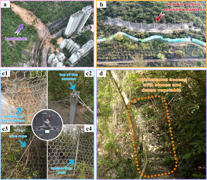
a A slope in Hong Kong that suffered a significant landslide in September 202331 due to Typhoon Haikui30. b Flexible debris-resisting barriers constructed on a slope to stop landslides. c Inspection targets of the flexible debris-resisting barriers. d Inspection maintenance access with stones and dense vegetation.
These barriers, however, are challenging to access due to their mid-slope placement and environmental changes over time (e.g., the growth of vegetation and trees). Therefore, regular inspections are important to ascertain the proper functioning of these barriers, particularly steel flexible barriers, a task known as slope inspection. Any anomalies, such as accumulation of debris behind barriers (Fig. 1c1) or severe corrosion of the steel components, may call for subsequent maintenance and repair works. These inspections encompass a comprehensive assessment of various aspects related to the flexible debris-resisting barriers, including the steel components, such as the wire ropes positioned atop the barriers (Fig. 1c2), the inclined wire ropes (Fig. 1c3), and the supporting posts (Fig. 1c4), to ensure the stability of the barriers. Diligently conducting these inspections ensures that the flexible barrier can effectively mitigate the impact of debris when it becomes necessary.
Currently, the maintenance agent of the debris-resisting barrier employs a manual inspection approach. Maintenance access is constructed along the flexible debris-resisting barriers on the slope to provide safe access for the inspecting personnel. However, the location of these barriers necessitates the construction of long maintenance access to access these barriers from public roads. As shown in Fig. 1d, the lengthy maintenance access, combined with the steep terrain, leads to high construction costs and imposes an increased workload on the inspecting personnel. Additionally, dense vegetation and hostile environments (e.g., steep rugged stairs, insects) are not suitable for inspecting personnel to stay. Furthermore, the maintenance access could be misused by unauthorized personnel to access nearby residential areas, which have raised considerable concerns among the residents.
Compared to manual inspection, unmanned aerial vehicles (UAVs)-based inspection possesses unique advantages and potential applications in slope inspections. Firstly, UAVs offer the capability to navigate complex terrains, covering wide areas and accessing areas that are difficult for humans or ground mobile robots to reach. They also provide rich terrain and obstacle data through onboard sensors such as LiDAR and cameras. Additionally, the deployment of UAVs reduces the need for human labor, mitigates operational risks, and enhances work efficiency. Moreover, the utilization of UAVs can potentially eliminate the necessity for access construction and maintenance, resulting in substantial cost savings and reduced criminal activities.
However, applying UAVs to slope inspections in dense vegetation presents several challenges. Firstly, for platform, the mechanical structure of the UAV must be systematically designed, considering factors such as maneuverability in narrow areas, flight time, and the types of onboard sensors required for effective inspections. Secondly, for localization, traditional GPS-based methods become unreliable under the canopy. UAVs need to rely on onboard sensors such as LiDAR and cameras to achieve accurate localization. Thirdly, for mapping, It is necessary to use data from onboard sensors to rapidly and accurately update information about thin objects in the map, such as thin tree branches, wire ropes, and fine nets on barriers. Finally, for planning and control, UAVs must effectively mitigate wind disturbances while responding smoothly and quickly to avoid dynamic objects, enabling safe navigation amidst swaying tree branches and other disturbances in the wild.
Many works2,3,4,5,6,7,8,9 deploy UAVs for inspection tasks on structures such as bridges, power lines, and buildings. These UAVs are capable of conducting inspections in areas away from obstacles. Limitations such as the larger aircraft size or the lack of comprehensive navigation algorithms render these approaches unsuitable for narrow-area inspection. Some studies and commercial UAVs incorporate additional mechanical structures to access narrow areas, such as protective enclosures around the propellers10,11,12,13,14, foldable arms15,16,17,18,19, or robotic arms equipped with cameras20,21,22. However, UAVs with such mechanisms generally lack obstacle avoidance capabilities, making them impractical for slope inspection under dense vegetation. Studies in refs. 23,24,25,26,27 attempt to control UAVs through narrow gaps by whole-body motion planning (i.e., SE(3) planning), but in dense vegetation, the complexity and irregularity of obstacles make it challenging to optimize SE(3) trajectories. Currently, commercial UAVs such as DJI Mavic 328 and Skydio 2 plus29, equipped with multiple sensors and employing navigation algorithms for obstacle avoidance in sparser environments, demonstrate practicality. However, the stereo disparity method used by the DJI Mavic 3 is susceptible to lighting changes, while the learning-based approach of the Skydio 2 plus suffers from data scarcity in extreme environments such as dense vegetation, resulting in lower accuracy of visual depth measurements compared to LiDAR for slope inspection. In addition to the low accuracy of these visual measurements, their obstacle avoidance functionality restricts UAVs from flying in narrow areas due to the paramount concern for safety. As far as we know, no existing research or commercial UAV has presented an effective solution that can be applied for slope inspection under dense vegetation.
To address the challenges of slope inspection under dense vegetation, we develop a LiDAR-based quadrotor with a comprehensive software system, as shown in Fig. 2 (Supplementary Movie 1). The quadrotor’s design fully considers the requirements for slope inspection, incorporating a high-performance navigation system that enables the quadrotor to maneuver through narrow spaces and agilely avoid small obstacles such as thin branches and ropes. An onboard high-definition digital video transmission system delivers a low-latency image feed with a delay of only 40 ms, providing timely feedback for the pilot on inspection targets. Given that slopes in Hong Kong currently lack digital models, predefining inspection targets for autonomous inspection is impossible. Therefore, our quadrotor operates in a human-in-the-loop mode. In this mode, the pilot determines the inspection targets impromptu from the transmitted video and commands the quadrotor’s high-level flight direction via the joysticks on the remote controller. On the other hand, the quadrotor navigation system attempts to fly along the specified direction meanwhile avoiding obstacles on the way. This mode enables the pilot to focus solely on the inspection task without concerns about avoiding obstacles, thus enhancing inspection efficiency. During the inspection process, our quadrotor produces a high-accuracy 3D point cloud reconstruction of the environments in real-time. The 3D models are instrumental in constructing digital assets and facilitating further data analysis.
Fig. 2: System overview of our LiDAR-based quadrotor for slope inspection.
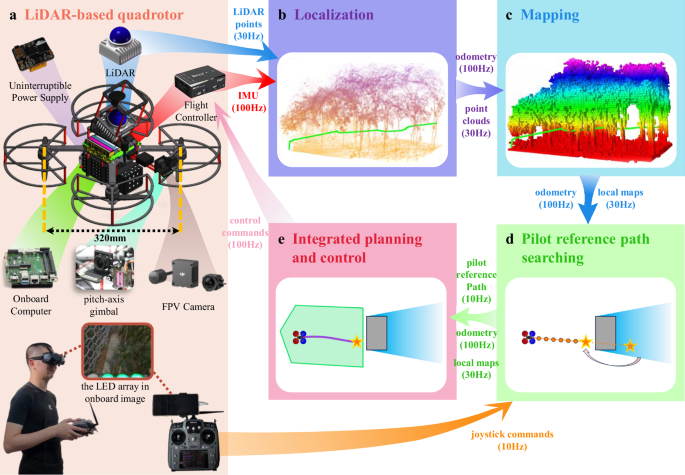
a The detailed hardware configuration of our LiDAR-based quadrotor. b The localization module employs Fast-LIO2, which utilizes an iterative error state Kalman filter and incremental kd-Tree. c The mapping module constructs a robocentric occupancy grid map, ROG-Map, with improvements tailored for slope environments. d The pilot reference path searching generates a coarse reference path from the pilot’s joystick commands. e Our quadrotor adopts an integrated planning and control framework (IPC), which directly generates control commands (e.g., angular velocity references and throttle) from the coarse reference path by solving a model predictive control (MPC) problem.
To assess the feasibility of our system solution for slope inspection, we first conduct functional tests on our quadrotor in non-operational scenarios (Supplementary Movie 2). Subsequently, invited by CEDD for visual inspection of flexible debris-resisting barriers and other geotechnical features, we deploy our quadrotor in six field environments (Supplementary Movies 3 and 4), including five flexible debris-resisting barriers located in dense vegetation and one slope that experienced a landslide caused by a rainstorm. In all these six field experiments, our quadrotor effectively accomplishes the assigned inspection tasks. Additionally, benchmark comparisons with DJI Mavic 3 regarding assisted obstacle avoidance flight (Supplementary Movie 5), demonstrate that our LiDAR-based quadrotor outperforms the most advanced commercial UAVs. Particularly, our quadrotor can avoid small obstacles on actual slopes and navigate safely through dense vegetation. As a result, this work represents a significant milestone in transitioning LiDAR-based quadrotors from laboratory settings to real-world applications, pioneering a new standard for UAV-based inspection in hazardous and hard-to-access environments.
Results
We demonstrate the assisted obstacle avoidance capabilities of our LiDAR-based quadrotor through extensive real-world experiments. First, we evaluate its performance in non-operational scenarios, confirming that our quadrotor can navigate safely through narrow spaces and avoid dynamic objects. Subsequently, our quadrotor is deployed to six actual slopes with dense vegetation in Hong Kong. Throughout all six field experiments, our quadrotor successfully performs close-up photo inspections of flexible debris-resisting barriers while navigating safely in complex environments. Finally, we conduct comparative experiments in the field environments with DJI Mavic 3 to further showcase the assisted obstacle avoidance capabilities of our quadrotor.
Functional tests in non-operational scenarios
We conduct functional tests of the quadrotor’s assisted obstacle avoidance function in two typical non-operational scenarios, namely the narrow environment and the dynamic environment.
In the narrow environment, the surroundings are enclosed by fine nets, with several boxes and thin rods in the middle, as shown in Fig. 3a1. To enhance the ability to navigate through narrow areas, we set the user-defined obstacle avoidance distance (represented by the blue line in Fig. 3a2) equal to the quadrotor’s size. As shown in Fig. 3a2, the distance dmin between the quadrotor’s center and the nearest obstacles remains greater than the quadrotor’s size, suggesting a successful obstacle avoidance throughout the whole test. The achievement of obstacle avoidance is primarily attributed to the robustness and effectiveness of the navigation algorithm (see “Methods”). The mapping module constructs high-resolution occupancy maps, effectively updating the corresponding grid cells in the map with small objects (e.g., fine nets or thin rods) detected by the LiDAR scans. Additionally, the pilot reference path searching module efficiently generates a collision-free reference path based on joystick commands. Subsequently, the integrated planning and control (IPC) module achieves high-precision control, ensuring the quadrotor safely arrives at the target point.
Fig. 3: Functional tests of the assisted obstacle avoidance function in non-operational scenarios.
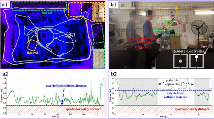
a Assisted obstacle avoidance flight in a narrow environment. In a1, the gray curve represents the quadrotor’s flight trajectory, which is about 99.46 m long. The green box represents the fine nets, and the orange box represents a scaffold with thin rods. In a2, the distance between the quadrotor’s center and the nearest obstacles is greater than the quadrotor’s size during the flight. b The third person view of the assisted obstacle avoidance flight in dynamic environment. In b1, as the personnel approaches the quadrotor, the quadrotor moves away from the personnel to avoid collisions, despite adverse joystick commands. In b2, as the personnel approaches the quadrotor, the distance between the quadrotor’s center and the nearest obstacles remains constantly greater than the quadrotor’s size throughout the flight.
Next, we evaluate the assisted obstacle avoidance function in dynamic environment, as illustrated in Fig. 3b1, where the personnel and the quadrotor move towards each other. Under the assisted obstacle avoidance function, the quadrotor ignores the remote control commands directing it towards the personnel and instead maneuvers to avoid him. In this experiment, the user-defined obstacle avoidance distance is set to 0.9 m to provide the quadrotor with a larger clearance for reacting and avoiding dynamic objects. As depicted in Fig. 3b2, although the motion of the dynamic object leads to the distance between the quadrotor and the obstacle being smaller than the user-defined obstacle avoidance distance, the distance remained bigger than the quadrotor safety distance. This is achieved by the low system latency of our navigation algorithm (see “Methods”). Upon receiving a LiDAR scan, the mapping module promptly updates the obstacles in the probability and inflated map. Subsequently, the pilot reference path searching module generates a new local goal in the Known Free region and a reference path reaching the new goal. This reference path is then leveraged by the IPC module to enable the quadrotor to rapidly respond and navigate towards a safe area. By successfully conducting these two test scenarios, we validate the feasibility of the quadrotor’s assisted obstacle avoidance function.
We invite readers to watch Supplementary Movie 2, to get a more intuitive understanding of the functional tests of our quadrotor in non-operational scenarios.
Field experiments in slope scenarios
To validate our system’s suitability for slope inspection under dense vegetation environments, we collaborate with the CEDD to deploy the quadrotor in the field and utilize the onboard camera for close-range visual inspection of the barriers. We conduct experiments at six different locations, including five slopes covered with dense vegetation and one slope recently experienced a landslide as a result of the 2023 Hong Kong rainstorm and floods caused by the landfall of Typhoon Haikui30. The six field experiments are summarized in Table 1. The third field experiment, conducted next to the Yiu Hing Road, involves a slope that has just experienced a landslide31, where the quadrotor conducts close observation of the barriers and stones in a relatively wide space. The other five field experiments consist of slopes with dense vegetation, where the quadrotor performs close-range photographic inspection of the flexible debris-resisting barriers in narrow spaces.
Table 1 Flight data from six field experiments

With the assistance of obstacle avoidance functionality, our quadrotor assists the pilot in close-range visual inspection of flexible debris-resisting barriers and stones resulting from landslides (Fig. 4a), maneuvering through dense tree canopies (Fig. 4b), avoiding thin dropping vines (Fig. 4c), and navigating through narrow tree branches (Fig. 4d). Ultimately, our quadrotor completes all six field experiments, demonstrating its suitability for slope inspection in dense vegetation environments. The flight trajectory of each experiment is superimposed on the slope drawing provided by the CEDD, the point cloud map built online by our navigation system, and the example photos taken during the inspection are shown in Fig. 5. These outputs provide the Hong Kong CEDD with detailed and valuable information about the inspected areas, enabling thorough analysis and assessment of the flexible debris-resisting barriers’ condition.
Fig. 4: Our quadrotor performs slope inspection in field environments.
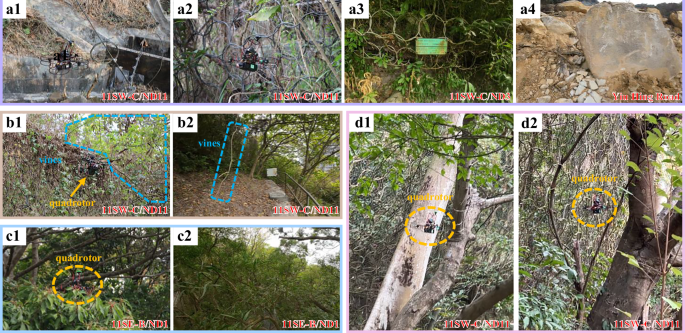
The text in the lower-right corner of the image corresponds to the experimental location in Table 1. a Quadrotor performing close-range inspection of flexible debris-resisting barriers (a1–a3) and stones caused by landslides (a4). b Quadrotor avoiding thin dropping vines. c Quadrotor maneuvering through dense tree canopies. d Quadrotor navigating through narrow tree branches.
Fig. 5: Flight data of our LiDAR-based quadrotor during slope inspection
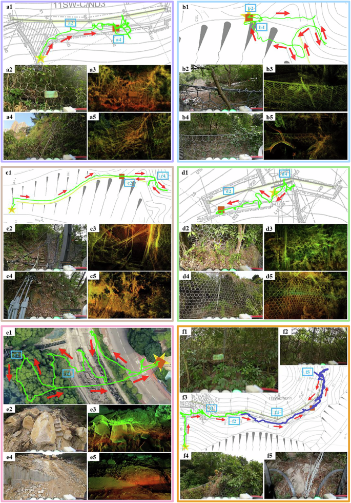
The green and purple curve represents the flight trajectory of the quadrotor, the yellow star represents the take-off point, and the brown box represents the landing point. a The field experiment of 11SW-C/ND3 slope next to Victoria Road, Pokfulam. b The field experiment of 11SE-B/ND2 slope next to Lei Yue Mun Estate. c The field experiment of 11SE-B/ND1 slope next to Lei Yue Mun Estate. d The field experiment of 11SW-C/ND6 slope next to Victoria Road, Pokfulam. e The field experiment of a slope next to Yiu Hing Road. f The field experiment of 11SW-C/ND11 slope next to Victoria Road, Pokfulam.
Throughout these six field experiments, the quadrotor benefited from the accurate perception of thin objects provided by the LiDAR sensor. This accurate perception allows our quadrotor to construct high-resolution local occupancy grid maps (map size: 10 × 10 × 10 m, resolution: 0.05 m) in the mapping module and update the occupancy status of grid cells containing moving branches and other thin objects. Moreover, thanks to the assisted obstacle avoidance function, our quadrotor is capable of safely approaching inspection targets, such as flexible debris-resisting barriers, at distances as small as the quadrotor’s size. This enables the quadrotor to capture high-definition images for subsequent detailed analysis. Additionally, despite encountering varying degrees of natural wind disturbances (average wind speed: 4.17 m/s), the quadrotor effectively suppresses these disturbances without compromising flight performance, due to the real-time generation of optimal control actions by the IPC module.
To gain a more comprehensive understanding of our quadrotor’s real-world performance in field experiments, we invite readers to watch Supplementary Movies 3 and 4. The movie provides a detailed showcase of our quadrotor’s performance during the field experiment of the 11SW-C/DN11 slope next to Victoria Road, Pokfulam. Moreover, we present first-person videos recorded during the other five field experiments.
Benchmark with commercial drones
DJI Mavic 328, as one of the most advanced commercial drones, is equipped with up to eight wide-angle cameras and incorporates the advanced pilot assistance system (APAS 5.0) algorithm for high-level flight assistance, enabling omnidirectional obstacle sensing. It offers three obstacle avoidance modes: Brake, Normal Bypass, and Nifty Bypass, allowing pilots to customize the settings based on the environments and their preferences. In Brake mode, the DJI Mavic 3 comes to an immediate stop if in the flight direction an obstacle is detected. In Normal Bypass and Nifty Bypass modes, the DJI Mavic 3 can bypass obstacles, but in Nifty Bypass mode, it maintains a smaller clearance with obstacles, so possessing a higher passability but also a higher risk of collision. In sum, among these three modes, the Brake mode provides the highest level of flight safety, followed by the Normal Bypass mode, and the Nifty Bypass mode performs the least effectively. However, in terms of accessibility in narrow areas, the order is reversed, with Nifty Bypass mode performing the best, Normal Bypass mode being in the middle, and Brake mode performing the worst.
To further validate the suitability of our quadrotor for slope inspection in dense vegetation, we conduct experiments on the 11SE-B/ND1 slope next to Lei Yue Mun Estate to compare its obstacle avoidance function with DJI Mavic 3 in different modes. When operating in Normal Bypass modes, DJI Mavic 3 exhibits highly conservative behavior in dense vegetation environments, as shown in Fig. 6a. In such an environment, despite a clear feasible corridor in the commanded direction, the DJI Mavic 3 prioritizes safety by maintaining a hover in place. The Brake mode behaves similarly to the Normal Bypass mode, as it remains hovering too. While the Brake mode prioritizes the most on safety thus being highly conservative, our testing revealed that when flying towards fine nets, it failed to execute the necessary stop maneuver, resulting in a collision, as shown in Fig. 6b1. This deficiency can be attributed to its limited perception capabilities, particularly when dealing with thin objects. In contrast, as depicted in Fig. 6b3 and Fig. 6b4, our LiDAR-based quadrotor effectively perceives the presence of fine nets ahead, actively refusing to follow joystick commands to fly towards them, thus ensuring flight safety.
Fig. 6: Benchmark with DJI Mavic 3.
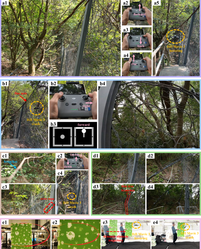
a DJI Mavic 3 exhibiting conservative behavior in Normal Bypass mode. Similar behavior is observed in Brake mode within the same environment. Despite a clear feasible corridor in the commanded direction (a1), the DJI Mavic 3 fails to follow the pilot’s commands (a2–a4) and remains hovering in place (a5). b Comparison of obstacle avoidance between the DJI Mavic 3 and our quadrotor when encountering fine nets. DJI Mavic 3 collides with the fine nets (b1) under the right command (b2). However, our quadrotor maintains a safe distance from the fine nets (b4) under the forward command (b3). c Obstacle avoidance performance of DJI Mavic 3 in Nifty Bypass mode. In this mode, it is easy to collide with branches (c1). When the pilot controls DJI Mavic 3 to fly forward and downward (c2), it collides with the wire rope (c3) and crashes (c4). d First-person view pictures taken by our quadrotor when inspecting the 11SE-B/ND1 slope next to Lei Yue Mun Estate. e In Nifty Bypass mode, DJI Mavic 3, despite its ability to perceive dynamic objects, cannot avoid them, resulting in crashes.
In Nifty Bypass mode, DJI Mavic 3 can fly in relatively open areas on maintenance access. However, it should be noted that the flight safety in this mode is the worst, as the rotor blades are prone to collide with tree leaves and thin branches, as shown in Fig. 6c1. Besides, DJI Mavic 3 can easily give the pilot a false feeling of loss of control. For example, it often refuses to follow the pilot’s commands when in proximity to the inspection targets, while exhibits unexpected large maneuvers and long flight distances when otherwise. Moreover, despite Nifty Bypass mode being the most aggressive, the pilot still lacks control when navigating narrow areas where the available space is less than twice the size of the DJI Mavic 3. Moreover, DJI Mavic 3 is even more susceptible to collisions and crashes while operating in this mode. When directed by the pilot to fly in the forward downward region (Fig. 6c2, it fails to detect and avoid the wire rope shown in Fig. 6c3, resulting in a collision depicted in Fig. 6c4.
Overall, in dense vegetation environments, the Brake mode and Normal Bypass mode of the DJI Mavic 3 prove to have insufficient ability to navigate through dense crowded vegetation environments and encounter frequent immediate stops in the presence of clear flight passage. Moreover, even in the most conservative Brake mode, the DJI Mavic 3 fails to perceive fine nets, resulting in collisions. The Nifty Bypass mode of the DJI Mavic 3 has improved passability in dense vegetation, but at the cost of much lower safety level, often leading to collisions with small objects, such as tree leaves, tree branches, and wire ropes. On the other hand, our LiDAR-based quadrotor performs exceptionally well in the same test scenario at the 11SE-B/ND1. As shown in Fig. 6d, our quadrotor maneuvers agilely through narrow areas while still roughly following the pilot’s commands. Furthermore, our quadrotor effectively avoids collisions with small objects such as thin tree branches (Fig. 6d3), successfully executing the necessary stop maneuvers when encountering fine nets (Fig. 6b4). The reliable performance of our quadrotor is a result of the carefully engeered system and its modules. First, thanks to the high-precision measurement capabilities of LiDAR and the high-resolution (0.05 m) of the mapping module, our quadrotor can effectively perceive fine nets and classify them as occupied within the probability map. Second, the pilot reference path searching module effectively generates collision-free reference paths based on joystick commands, thus avoiding collisions with small obstacles (e.g., thin tree branches and fine nets) in the environment. Third, the high-precision control and low-latency characteristics of the IPC module (which generates angular velocity and throttle control commands with a delay of less than 3.5 ms) enable our quadrotor to swiftly and safely reach the target point.
Finally, in terms of dynamic obstacle avoidance, as shown in Fig. 6e, in Nifty Bypass mode, the DJI Mavic 3 is able to perceive dynamic obstacle ahead but fails to avoid it, further reducing its safety assurance. In comparison, our quadrotor can successfully evade slow-moving dynamic objects, as shown in Fig. 3b1. This performance advantage is primarily attributed to the pilot reference path search and the IPC modules. The pilot reference path search actively generates a reference path free of obstacles in less than 1 ms, while the IPC module computes control actions in real-time at a high frequency of 100 Hz, enabling the quadrotor to respond rapidly to dynamic obstacles. The complete comparison experiments between our quadrotor and the DJI Mavic 3 can be found in the Supplementary Movie 5.
Discussion
A key advantage of our LiDAR-based quadrotor lies in its superior obstacle avoidance capabilities, enabling it to avoid various obstacles in slope environments, including thin tree branches, wire ropes, and fine nets on barriers. Notably, our quadrotor can detect fine nets composed of 4 and 10 mm metal wires within 3.53 m and detect 16 mm wire ropes within 7.10 m. This feature establishes a foundation for human-in-the-loop operations. In slope inspection under dense vegetation, where prior maps are often unavailable, the human-in-the-loop mode enables pilots to make real-time decisions and direct the quadrotor toward specific targets while it autonomously avoids obstacles during flight. This mode provides a high degree of flexibility and adaptability, making it suitable for inspection tasks in unknown and unstructured environments, particularly in scenarios where inspection targets must be decided impromptu, such as post-landslide slope inspection.
Despite these promising results, some challenges remain. Our quadrotor’s reliance on the pilot reference path, while enhancing flexibility, continues to limit its scalability in large-scale inspection. Future work could incorporate machine learning algorithms to facilitate inspection target detection and task execution, aiming to reduce pilot efforts. Moreover, while the system performed well under normal wind disturbances (wind speed less than 5.56 m/s), its stability under extreme weather conditions, such as strong winds or heavy rain, requires further validation. Since these conditions are common in landslide-prone areas, enhancing the quadrotor’s resilience to adverse environments is imperative.
In conclusion, our LiDAR-based quadrotor offers an efficient and reliable solution for slope inspection under dense vegetation. Its exceptional obstacle avoidance capabilities in cluttered environments and flexible human-in-the-loop inspection mode also hold significant potential for broader applications, such as agriculture32, infrastructure development33, industrial inspections7, and search and rescue operations34,35. Moving forward, we aim to increase the system’s automation, utilizing the identified inspection target points and point cloud models from initial human-in-the-loop flights to support subsequent automated inspections. In this enhanced mode, our quadrotor would autonomously navigate to each inspection target point within the same environment, thereby reducing the operational burden on the pilot. We believe that with further automated operation, this LiDAR-based quadrotor will become increasingly effective in supporting inspection tasks across complex, large-scale environments.
Methods
The system overview of our LiDAR-based quadrotor for slope inspection is shown in Fig. 2. For platform, considering that LiDAR can directly provide high-precision 3D measurements compared to visual sensors, we developed a LiDAR-based quadrotor. For localization, we employ our previous work, FAST-LIO236, a robust LiDAR-inertial odometry framework capable of operating in GPS-denied environments. For mapping, we enhance ROG-Map37, which constructs real-time high-resolution sliding occupancy grid maps. By incorporating three enhancement techniques, namely the unknown grid cells inflation, infinite points ray casting, and incremental frontier update, our quadrotor can effectively identify the correct gird occupancy states in case of no LiDAR returns or with returns caused by thin objects, allowing for efficient avoidance of potential obstacles in dense vegetation. For path searching, we search a pilot reference path consisting of two segments, ensuring alignment with the pilot’s intent while avoiding static and dynamic obstacles. For planning and control, we employ the IPC framework38, enhancing safety in dense vegetation by generating safe flight corridor (SFC) exclusively within Known Free space. To the best of our knowledge, we are the first to propose a practical and comprehensive UAV solution for slope inspection under dense vegetation.
The authors affirm that human research participants provided informed consent for publication of the images in Figs. 2, 3, and 6.
LiDAR-based quadrotor
The detailed hardware configuration of our LiDAR-based quadrotor is shown in Fig. 2a. Given that LiDAR, unlike GPS and cameras, can operate independently of external devices and remains unaffected by environmental conditions, our quadrotor utilizes the Livox Mid-360 LiDAR39, weighing only 265 g, as its primary sensor. This LiDAR employs a non-repetitive scanning approach, accumulating data over time to generate dense point clouds. Additionally, its 360-degree horizontal and 59-degree vertical fields of view enable a wide range of scene perception, enhancing the robustness of the state estimation. For computation, we employ the Intel NUC minicomputer equipped with an Intel i7-1260P CPU (operating at 4.7 GHz), providing substantial computational power for real-time processing tasks. To enable real-time observation of the flight process by the pilot and capture photos and videos of specific areas, we use an FPV camera DJI O3 Air Unit40, a high-definition digital video transmission system, with the DJI Goggles 241. This video transmission system offers an impressively low-latency of 40 ms, providing timely feedback on the surrounding environment for the pilot. Moreover, it supports recording 4 K videos at a high frame rate of 120 Hz, enabling in-depth post-analysis after the flights. In order to enlarge the field of view (FOV) of the FPV camera, so as to observe both the top and bottom of the flexible debris-resisting barriers on the slope, we install the camera on a pitch-axis gimbal. The pitch angle of the gimbal is commanded by the remote controller in real-time during the flight. We use an LED array to keep track of the quadrotor’s battery level in real-time. The LED array consists of four LEDs, indicating the battery percentage. They display green for battery percentage over 40%, red for battery percentage between 25% and 40%, and flash red for battery percentage below 25%. The LED arrays are installed in front of the camera and their status is visible in the streamed video, so the remote operator can initiate a return flight before the battery is out. To enhance quadrotor safety, carbon fiber propeller guards are meticulously designed and installed to minimize the risk of propeller-related accidents. These guards protect both the quadrotor and the pilot, ensuring safe and reliable operation. To reduce deployment time, we design an uninterruptible power supply, ensuring uninterrupted power supply to onboard computers and electronics during battery replacement. Additionally, the quadrotor is equipped with the CUAV Nora+ flight controller42, complemented by the CUAV NEO 3 with the NEO-M9N module for GPS data collection (note that GPS data is not used for localization).
After these devices are integrated into the airframe composed of carbon plates and aluminum columns, we conduct tests on the developed quadrotor. The quadrotor features a motor-to-motor distance (i.e., wheelbase) of 320 mm and overall dimensions of 422 mm in length, 422 mm in width, and 285 mm in height. With a total mass of 2.1 kg, the quadrotor achieves a thrust-to-weight ratio of 3, ensuring efficient and stable flight performance. Additionally, the maximum flight time is measured to be 12 min. In the actual field tests, our quadrotor has an average flight speed of 1.5 m/s, corresponding to an approximate flight distance of 1080 m. In practice, this flight distance may vary depending on specific weather conditions and flight characteristics.
Localization
The localization module plays a crucial role by providing real-time state estimation (position, velocity, and attitude) to the quadrotor’s controller. Additionally, it transforms the LiDAR points in the local frame into the world frame to construct subsequent navigation maps. In this work, our adapted FAST-LIO2 utilizes the 30 Hz raw point cloud from LiDAR and the 100 Hz IMU. By performing IMU pre-integration, FAST-LIO2 can provide low-latency state estimation at a frequency of 100 Hz with a latency of less than 1 ms. Additionally, it generates world frame registered point clouds at a scan rate of 30 Hz, producing about 200,000 points per second with a latency of less than 10 ms.
Mapping
The mapping module is responsible for constructing high-resolution navigation maps based on the odometry and world frame registered point clouds provided by the localization module. These maps accurately represent the terrain and obstacles, ensuring safe quadrotor navigation through dense vegetation. In our previous work, ROG-Map37, a zero-copy map sliding strategy is utilized to maintain two local occupancy grid maps (OGMs). The first local map is the probability map, where grid cells are classified as Occupied, Unknown, or Known Free based on the occupancy probability updates derived from ray casting. The second local map is the inflated map, utilized for robot navigation in configuration space by inflating obstacles. This map adopts an incremental update mechanism, with grid cell states being classified as either Inflation or No Inflation, depending on the probability values from the probability map. In this work, we introduce three enhancements to ROG-Map specifically tailored for dense vegetation environments: unknown grid cells inflation, infinite points ray casting, and incremental frontiers update.
Unknown grid cells inflation
In motion planning, UAVs are often treated as point masses, and the occupied inflation radius rocc is employed to expand the obstacles in the inflated map. This inflation enables the UAV to avoid known obstacles during planning. However, existing methods43,44,45,46,47,48,49 often make the simplistic assumption that unknown areas are traversable. In reality, unknown areas may contain obstacles, presenting potential safety risks. To ensure a higher level of safety, it is necessary to not fly in unknown regions and further expand Unknown grids in the probability map by a radius runk to consider the UAV size and safety clearance. Due to the unknown grid cells inflation, a grid cell state in the inflated map is redefined as Occupied Inflation, Unknown Inflation, and No Inflation.
The method of unknown grid cells inflation is similar to the incremental update mechanism used in the original ROG-Map, which is achieved by maintaining a counter for each grid cell. Therefore, each grid cell in the inflated map maintains two non-negative counters, namely Nocc and Nunk, which define the grid cell states. A grid cell is considered to be in the Occupied Inflation if Nocc > 0. If Nocc = 0 but Nunk > 0, the cell is classified as Unknown Inflation. Only when both Nocc = 0 and Nunk = 0, the cell regarded as No Inflation. Considering the inflation efficiency, it is necessary to determine the set of inflated grid cells for each Occupied or Unknown Grid Cell in advance. Such sets, denoted as Iocc and Iunk, are expressed as grid cell coordinates offsets relative to the input Occupied or Unknown Grid Cell, and are computed offline from the respective inflation radius runk and rocc. Note that the unknown inflation radius runk may differ from the occupied inflation radius rocc to give more flexibility. These offset coordinates are then added to the coordinates of the input grid cell to determine this grid cell’s inflated occupied and unknown neighbors. During the initialization of the inflated map, all grid cells of the probability map are Unknown, therefore, Nocc is set to 0, and Nunk is set to the size of Iunk (including the grid cells at the map boundary, since spaces outside the map boundary are also Unknown). Figure 7a illustrates a simplified 2D process of updating from a probability map to an inflated map. Once occurring a change from an else state to Occupied in the probability map, the corresponding grid cell in the inflated map, along with its inflated neighboring grid cells defined by Iocc, increments Nocc by 1. Conversely, if the state changes from Occupied to else, Nocc is decremented by 1. Similarly, when the state changes from an else state to Unknown, the corresponding grid cell in the inflated map, along with its inflated neighboring grid cells defined by Iunk, increments Nunk by 1. Conversely, if the state changes from Unknown to else, Nunk is decremented by 1. By maintaining these two counters, we can effectively inflate the Unknown grid cells and update the inflated map in real-time based on changes of the grid cell state in the probability map.
Fig. 7: Three enhancements of the mapping module.
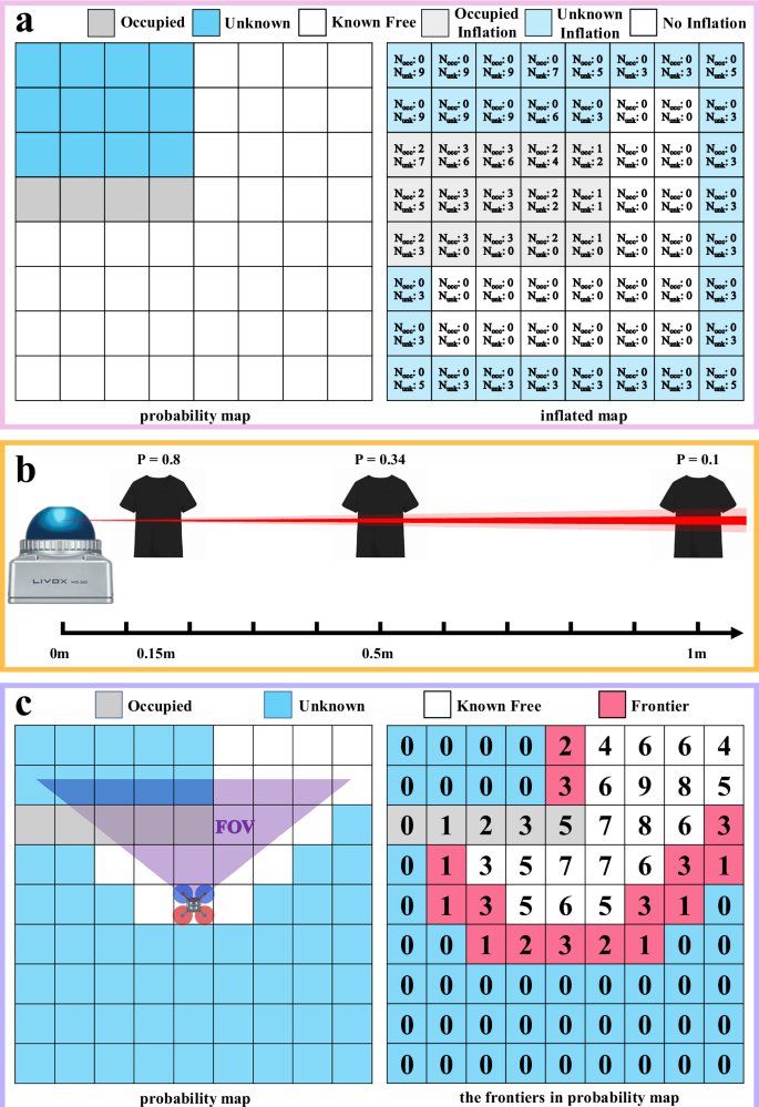
a The unknown grid cells inflation in the 2D case. In this case, both the resolution of the probability map and the inflated map are set to 0.1 m, and the inflation radius, rocc and runk, are both set to 0.2 m. As a result, the quantities of Iocc and Iunk are equal, with both being 9. b Characteristics of Livox Mid-360 LiDAR scanning on clothing. As the distance increases, the ratio of invalid measurement points to the total measurement points decreases. When the distance exceeds 1 m, this ratio approaches zero, indicating that nearly all measurement points are considered valid. c The incremental frontiers update in the 2D case.
Infinite points ray casting
As an active sensor, LiDAR perceives the environment by emitting laser beams and receiving their return pulses. These laser beams that provide measurement are known as valid measurement points. However, certain situations can result in invalid measurement points. Firstly, when the LiDAR faces the sky, it is unable to measure distances due to the absence of returns. These LiDAR beams are referred to as infinite points. Secondly, when LiDAR scans nearby objects, the returned pulses are lumped into the pulses reflected by the LiDAR internal parts (e.g., prisms, glasses), causing the pulse return due to nearby objects to be indistinguishable from that due to the LiDAR internal parts. Points causing such a phenomenon are defined as nearby blind points. In the Livox Mid-360 LiDAR39 (and also many other LiDARs), the two cases are not distinguished, both leading to a point at LiDAR origin (i.e., invalid measurements). The inability to distinguish infinite points can cause a large number of grid cells lying in the direction of the sky or far buildings having their grid cell state not updated and remain Unknown. To update these grid cells to a Known Free state, we need to distinguish the infinite points from nearby blind points and fully utilize them for ray casting.
We analyze the characteristics of nearby blind points when scanning objects with the Livox Mid-360 LiDAR through an experiment. In the experiment, we scan a cloth at different distances within LiDAR’s fixed FOV and record the ratio of invalid measurement points to the total number of measurements. As shown in Fig. 7b, when the cloth is located within a distance of 1 m, the ratio of invalid measurements gradually decreases as the distance increases. Beyond 1 m, the proportion stabilizes and approaches zero. These results indicate that the nearby blind points caused by objects within 1 m account for approximately 10% to 80% invalid measurements, rendering the infinite points indistinguishable in such cases. Only when there are no close-proximate objects (e.g., within 1 m), the invalid measurements can be considered as infinite points.
Based on the characteristics of nearby blind points analyzed above, we can extract infinite points by verifying the presence of close-proximate Occupied grid cells in the probability map. Specifically, when receiving LiDAR data, we extract the valid measurement points and invalid measurement points. For the valid measurement points, we perform ray casting to update the probabilities of the grid cells corresponding to obstacles. Next, for each invalid measurement point, we check if there are occupied grid cells within a distance of 1 m along its ray direction. If no occupied grid cells are found within the 1-m ray, we identify this invalid measurement point as an infinite point. Subsequently, within the local map region, we use these identified infinite points for ray casting to update the probability map. This process, known as infinite points ray casting, effectively extracts infinite points from the invalid measurement points, enabling the updating of probabilities for grid cells in the direction of the sky.
Incremental frontiers update
Due to the inability of the LiDAR sensor to scan the internal regions of obstacles and the limited LiDAR FOV, numerous grid cells in the probability map will be marked as Unknown. Leveraging frontiers can effectively reduce the computation time required for SFC generation, as frontiers represent the boundary of the unknown region and are typically much fewer in quantity than Unknown grid cells. In the work50, frontiers are defined as Known Free grid cells adjacent to Unknown grid cells. We slightly modify this definition and define frontiers as Unknown grid cells adjacent to Known Free grid cells. Considering that SFC is generated in the probability map, we need to label the frontiers in the probability map. Specifically, we introduce a counter Nf for each grid cell, indicating the number of Known Free grid cells among itself and its 26 neighbor grids. Fig. 7c illustrates a simplified 2D Incremental frontiers update process. During the initialization of the probability map, all grid cells are Unknown (including areas outside the map range), therefore, Nf is set to zero. When a grid cell state changes from Known Free to an else state, both the grid cell and its 26 neighboring grids decrement Nf by 1. Conversely, when the grid cell state changes from an else state to Known Free, both the grid cell and its 26 neighboring grid cells increment Nf by 1. If an Unknown grid cell has its Nf less than 27 but greater than zero, this grid cell is classified as a frontier. Incremental frontiers update allows us to replace a large number of Unknown grids with a small number of frontier grids, thereby reducing the computation time required for SFC generation.
Pilot reference path searching
In slope inspection, the pilot reference path searching module plays a pivotal role in assisted obstacle avoidance. This module first calculates a local goal and the quadrotor’s yaw reference based on the pilot’s joystick commands and odometry, followed by searching a reference path on the inflated map.
The calculation of the local goal and the quadrotor’s yaw reference is shown in Fig. 8a. To align with the pilot’s flight expectations in the first-person view, the joystick commands are treated as velocity command vjoy in the quadrotor’s yaw frame (a frame with only a rotation in the yaw direction to the world frame, with zero pitch and roll). Let R(ψ, 0, 0) be the rotation of the yaw frame with respect to the world frame, where ψ is the quadrotor’s yaw angle, the local goal in the world frame pg and the quadrotor’s yaw reference ψr can be computed as:

where podom is the quadrotor’s current position, △t is the joystick commands period (e.g., △t is 0.1 s when the joystick commands frequency is 10 Hz).
Fig. 8: Demonstrations of the pilot reference path searching module for assisted obstacle avoidance.
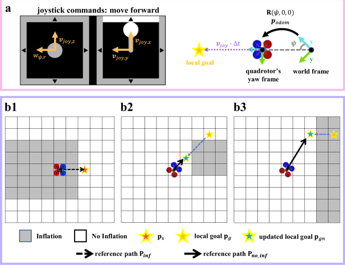
a Mapping the joystick commands to reference velocity in the quadrotor’s yaw frame vjoy and reference yaw angular velocity wψ,r. Then the local goal pg and the quadrotor’s yaw reference ψr is identified. b Schematic of reference path searching. If the quadrotor’s current position being in an Inflation (Occupied Inflation or Unknown Inflation) grid cell, a reference path Pinf is first searched to leave the inflation area (b1). If the pg is in No Inflation state but occluded by Inflation grid cells, the farthest visible No Inflation grid cell will be identified as the new pg (b2). If the pg is in Inflation state, a nearby No Inflation grid cell will be identified as the new pg (b3).
After calculating the local goal and the quadrotor’s yaw reference, the pilot reference path P is searched on the inflated map. This reference path consists of two segments. The first segment is a reference path in the Inflation region (comprising both Occupied Inflation and Unknown Inflation areas) Pinf, which guides the quadrotor away from inflation regions caused by dynamic objects (e.g., small branches or wires swaying by the wind) and reach a position ps in No Inflation regions. The second segment is the reference path in the No Inflation region Pno_inf, which continues to guide the quadrotor toward the local goal pg.
The detailed generation of the two path segments is as follows: For Pinf, initially, ps is set to podom and Pinf remains empty. If podom is in Inflation state, Pinf starts at podom and connects to the nearest No Inflation grid ps using a breadth-first search (Fig. 8b1). Then, Pno_inf connects ps to the updated local goal pgn. Initially, pgn is set to pg. If pg is in No Inflation state but there are Inflation grids along the connecting line to ps, the farthest No Inflation grid along this line is selected as pgn (Fig. 8b2). If pg is in Inflation state, a feasible local goal is first found using a breadth-first search (Fig. 8b3), and then the updated local goal is adjusted as in the previous case. Finally, the complete P is obtained as the union of the two path segments Pinf and Pno_inf.
It is worth noting that in the inflated map, we do not track or predict the dynamic objects’ movements. Instead, dynamic objects are treated together with static obstacles and subjected to inflation operations. The lack of dynamic objects tracking and prediction are compensated by the high planning and control rate of our overall framework, which can avoid dynamic objects in a purely reactive manner. While a larger inflation radius can provide the quadrotor with more reaction time and distance to avoid dynamic objects, it significantly reduces the available space in the inflated map, consequently decreasing maneuverability in narrow areas. Therefore, different obstacle avoidance requirements can be met by adjusting the occupied inflation radius rocc (i.e., the user-defined obstacle avoidance distance) in the inflated map. For instance, setting rocc to approach the quadrotor’s radius allows for flight in narrow areas. Alternatively, setting rocc to three times the quadrotor’s radius can effectively evade dynamic objects.
Integrated planning and control
The IPC module directly generates throttle and angular velocity references for quadrotor using odometry, probability map, and the pilot reference path. In our previous work38, IPC computes control actions for the quadrotor at a frequency of 100 Hz, allowing for rapid response to dynamic obstacles. Moreover, by integrating planning and control into a model predictive control (MPC) problem, IPC enhances the quadrotor’s ability to suppress external disturbances. These features allow the quadrotor to swiftly avoid small obstacles and resist natural wind disturbances in slope environments.
In this work, we further enhance flight safety in dense vegetation by generating SFC only within Known Free areas. Since no SFC can be generated along Pinf in the Inflation area, we only consider generating SFC along Pno_inf in the No Inflation area, which resides in the Known Free space of the probability map. Considering that the quadrotor’s flight speed in narrow spaces is low, we generate only one convex polyhedron as the SFC to reduce the computation load. We input the grid cells that are identified as Occupied or Frontiers, instead of Occupied or Unknown for improved efficiency, along with the seed, which is the point on the path Pno_inf that is closest to the quadrotor’s current position, to the polyhedron generation method51. The obtained polyhedron will intersect with the local map boundary (since the spaces enclosed by Occupied and Frontiers are Known Free when they are within the local map, see Fig. 7c) and shrink by the quadrotor’s size. A simplified 2D scenario for SFC generation is illustrated in Fig. 9.
Fig. 9: The SFC generation considering the unknown areas.
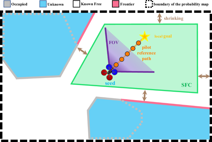
The grid cells along the pink lines represent Frontiers, while the grid cells along the gray lines represent Occupied. The orange line represents the pilot reference path, and the green polygon represents the generated SFC.
Following38, the reference path and SFC are used as the reference positions and hard constraints, respectively, for the MPC problem. The optimal control actions from the MPC are then transformed into commands for the quadrotor’s actuators through differential flatness52, which are finally tracked by a lower-level controller implemented on the autopilot to produce motor commands.
Data availability
All data is available in the main text. The source data presented in the manuscript have been deposited in Figshare and can be accessed at https://doi.org/10.6084/m9.figshare.29527079. Additional requests for data should be addressed to F.Zhang.
Code availability
Source code of this work has been provided on the GitHub repository. This code is freely accessible. All the information needed to install and use it, as well as any updates, can be found here: https://github.com/hku-mars/slope_inspection.


