


Please enter the answer below before you can view the full text.
8-2=
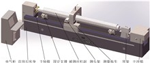
To solve the measurement problem of stroke error for heavy⁃duty screw pairs with diameters of 100 ~ 300 mm in key industries, building upon the experience of small and medium⁃sized screw measurement instruments, this study has optimized the overall configuration, critical components, and measurement⁃control systems while exploring manufacturing and assembly processes. A specialized measurement machine for heavy⁃duty screw pairs was successfully developed, enabling dynamic measurement of both lead error in heavy⁃duty screws and travel error in screw pair assemblies. Experimental results demonstrate that within a 4 m travel range, the instrument's optical axis exhibits maximum indication errors of 0.5 μm and 1.3 μm when positioned at 50 mm and 150 mm from the screw centerline, respectively. For the tested screw pair samples, the maximum deviations between the extreme values of all measured parameters do not exceed one⁃third of the tolerance specified for P1⁃grade screw pairs. These findings confirm that the measurement accuracy of this heavy⁃duty screw pair stroke measuring machine meets P1⁃grade requirements. The successful development of this instrument plays an important role in promoting the development of heavy⁃duty screw pairs and screw detection fields.
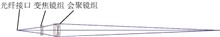
In laser ranging scenarios involving non⁃cooperative targets, the complex and diverse surface characteristics of these targets often result in low reflectivity and scattering of reflected light in various directions. Consequently, the optical energy returning to the measurement system is weak. To effectively collect the return optical energy and achieve precise focusing of the laser spot under such conditions, a high⁃precision laser zoom optical⁃mechanical system and auto⁃focusing control system have been designed. The optical structure of the system is optimized by incorporating a combination of collimating lens group, front lens group, movable lens group, rear lens group, and compensating lens group. This design ensures efficient beam focusing and maximizes energy, thereby enhancing the signal⁃to⁃noise ratio and stability across different ranging distances. Additionally, the focusing consistency of the system is improved by optimizing optical axis stability and mechanical structure layout. In terms of control methodology, an image recognition⁃based auto⁃focusing strategy is introduced. A high⁃resolution camera captures real⁃time images of the target laser spot. Image processing techniques are employed to extract key features such as spot diameter, shape, and clarity. These features are used to dynamically calculate optimal focal length adjustment parameters, enabling automatic closed⁃loop focusing via a stepper motor. Experimental results indicate that the system has a light spot centroid offset of no more than 65 μm within a working distance of 0.5 ~ 30 m, which meets the design requirements and can effectively achieve spot focusing.
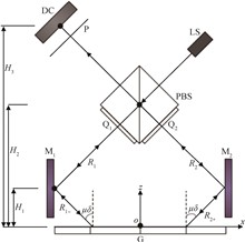
Aiming at the lack of more in⁃depth quantitative data for the study of the systematic errors of Littrow⁃type grating interferometers, the systematic errors of Littrow⁃type grating interferometers caused by the positioning accuracy of the components, namely, the systematic errors of the interferometers caused by the additional optical path differences due to grating rotation around the x, y, and z axes as well as mirror rotation around the y axis, were investigated in terms of the impact of the systematic errors on the displacement measurements of the interferometers. A mathematical model of the error caused by the change in optical path difference when the grating and mirror rotate around the axes was established, quantitatively analyzed, and the accuracy of the mathematical model was verified by experiments. The results show that: when the grating and mirror rotate around the x and z axes, no additional optical path difference is generated; when the grating rotates around the y axis, the systematic error will be generated and increase with the increase of the grating constant and the rotation angle; when the mirror rotates around the y axis, the error will be generated only when the rotation angles of the two mirrors are different, and the error will increase with the increase of the rotation angle of the two mirrors. After synthesizing the errors of the whole system, the undefined system error is ± 3.12 μm in high assembly level, and ± 17.75 μm in general level, which verifies the correctness of the theoretical simulation, and provides technical reference and theoretical support for the system design of the Littrow⁃type grating interferometer.
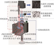
In order to meet the demand for high⁃precision automatic detection of multiple wafer defects during the manufacturing process of micro light emitting diode (Micro⁃LED) chips, a large⁃field⁃of⁃view polarisation dual⁃channel Micro⁃LED wafer defects automatic optical inspection system has been designed. The system integrates microscopic imaging technology with polarisation imaging technology, thereby enhancing the contrast of Micro⁃LED wafer defect images and enhancing the detection accuracy. The system utilises infinite conjugate microscopic objectives and barrel lenses, which expand the image area of wafer samples captured in a single exposure and improve the detection efficiency. Experiments have been conducted to verify the performance of the large⁃field⁃of⁃view dual⁃channel Micro⁃LED wafer defect optical inspection system, and the results demonstrate that: the system's magnification is 20, the illumination uniformity is up to 91.6%, and the maximum image field⁃of⁃view is 33 mm; The modulation transfer function (MTF) curve of the system is close to the diffraction limit at the Nyquist frequency of 31 lp / mm, which can satisfy the object resolving power of 0.8 μm. The system has been shown to enhance the information entropy, edge intensity, standard deviation and average gradient of polarimetric images in comparison to traditional grey⁃scale images by 25.6%, 24.9%, 33% and 173.3%, respectively. The large⁃field⁃of⁃view dual⁃channel Micro⁃LED wafer defect optical inspection system has been demonstrated to capture the characteristic information of different types of defects in real time, with high recognition efficiency, low missed detection rate and other advantages, providing a strong support for the high⁃precision inspection of Micro⁃LED wafer production quality.
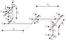
To study the nonlinear impact of calibration errors on the positioning accuracy of a robot's end⁃effector, a linkage analysis of end⁃effector pose calibration errors for a six⁃degree⁃of⁃freedom robot was conducted. Using the modified Denavit⁃Hartenberg model (MDH) constraints, a kinematic parameter model for a six⁃degree⁃of⁃freedom robot was established to analyze the spatial geometric relationships of the end⁃effector's pose transformation. The sources of robot calibration errors were examined, and the functional relationships between the coordinate systems of the measurement system were derived. Based on this, a calibration error propagation model for the robot's end⁃effector pose was constructed. A calibration system for a six⁃degree⁃of⁃freedom robot was set up to conduct experiments. Experimental results indicate that the primary sources of calibration error in robotic end⁃effector positioning include link length errors, joint offset errors, joint twist angle errors, and zero⁃position errors. The combined calibration error was measured as 2.66 mm, with relative uncertainties in the x, y, and z directions of 0.09%, 0.37% and 0.46% respectively. The research findings provide technical references for achieving precise positioning control of the robot's end⁃effector.
Cells perceive physical properties such as stiffness, elasticity, and topological structure of the microenvironment through the extracellular matrix, and utilize mechanosensitive proteins to respond to mechanical stimuli, thereby regulating behaviors such as proliferation, differentiation, and migration. Therefore, precise measurement of mechanical forces between cells and the matrix is crucial for studying mechanosensing and signal transduction. To measure the traction forces exerted by tumor cells on the matrix during migration, this study employs Traction Force Microscopy (TFM) technology. By real⁃time monitoring of the displacement of fluorescent microspheres embedded in the matrix and combining the mechanical properties of the matrix, high⁃precision traction force measurement at the subcellular scale is achieved using forward and inverse methods. The measurement results showed that tumor cells exerted traction forces of approximately 431.9 Pa in the protrusion regions and 153.9 Pa in the cell body regions during migration on the constructed matrix. This technology, with its advantages of high resolution, non⁃invasiveness, and real⁃time in situ detection, provides a new research approach for mechanical measurements at the micro⁃nano scale.