In this Letter, an effective method using a mode selective coupler (MSC), which is composed of a three-core fiber is presented to generate optical vortices (OVs). The conversions of OVs with different topological charges, and , are simulated in detail. We also prove that a higher-order topological charge can be obtained simply by changing the parameters of the fiber to increase the number of modes in the fiber. The polarization of OVs can be controlled as well.
Optical vortices (OVs), with a phase term of , where is the topological charge[1], possessing spatial polarization or phase singularities, have attracted considerable interest in recent years[2–4]. It has been paid great attention in many applications, such as high-density data transmission[5], quantum information processing[6], and optical spanner[7]. Driven by their distinctive properties, many attempts have been proposed to generate OVs, such as spatial light modulators (SLMs)[8], cylindrical lens converters[9], and spiral phase plates[10], which are generally bulky and expensive. Meanwhile, due to the compact, compatible, and high-efficiency of fiber, generating OVs in fiber has become a hot topic[11–13]. In previous works, the polarization of OVs is circular polarization[12,13], and linearly polarized (LP) OVs cannot be generated. In this Letter, we design a three-core mode selective coupler (MSC) to generate OVs, and the power coupling between them is studied as well. LP OVs in a step-index fiber can be easily generated.
MSCs, such as sensors[14], data transmission[15], acousto-optic modulators[16], and optical add–drop multiplexers[17], have been paid more attention. An MSC is composed of a single-mode fiber (SMF) and a multimode fiber (MMF), which are closely positioned and have the same cladding with a different radius[18]. When the fiber cores are brought into close proximity, power can be transferred between the fundamental mode in the SMF and the mode in the MMF if their propagation constants are matched by using dissimilar cores[19]. Recently, we find that not only can the power be transferred between the fibers but also the coupling behavior of the two-core MSC is dependent on the spatial orientation of the higher-order mode, as shown in Fig. 1[20–22]. However, in these previous works, little attention has been paid to generate OVs in MSCs, and only the power couplings of different modes in the MSC were analyzed. In 2011, Yan et al. proposed an approach to generate OVs in a fiber coupler consisting of a central ring and four external cores[23]. In 2012, Yan et al. proposed another way to generate OVs, where the fiber has a square core and a ring refractive index profile[24]. But, in those works, the fibers they used are special fibers, and the fibers are hard to fabricate. In this Letter, the properties of MSCs that consist of two step-index fibers are studied, and the generation of higher-order OVs using MSCs is simulated as well.
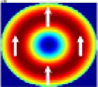
Figure 1.Cross section of an MSC. Fiber 1 is an MMF, fiber 2 is an SMF, and they have the same cladding. The distance between them is .
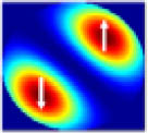
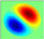
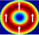
In referring to low-mode-number fibers, it is assumed that the index difference between the core and cladding is small so that the LP mode approximation can be used to study the MSCs[25]. As shown in Fig. 1, the cross sections of a fundamental mode, mode, and a higher-order mode, mode, are illustrated as an example, and the refractive indices of the cores of fiber 1 and fiber 2 are the same. The field orientation of the higher-order mode makes angle with the horizontal line and the arrows represent the polarization of the modes. There are two forms for all higher-order LP modes, which are the even mode () and the odd mode ()[25]. The operation of the MSCs is based on phase-matched evanescent coupling between two dissimilar fibers, and proper index profiles for the fibers must be chosen to ensure phase matching[18]. Figure 2 shows the dependencies of the effective refractive indices of the modes (, , , and modes), depending on the core design[19]. The dashed line is phase matched between them at [19], where is the effective index of the mode. It is assumed that the wavelength is , the indices of the core and cladding are and , respectively, the fiber separation between fiber 1 and fiber 2 is , and the core radius of fiber 1 and fiber 2 are and , respectively.
Sign up for Chinese Optics Letters TOC Get the latest issue of Advanced Photonics delivered right to you!Sign up now
Figure 2.Effective refractive indices of the modes in a fiber. The dashed line is phase matched between different modes at . The wavelength, and the indices of the core and the cladding are 1.55 μm, , and , respectively, and the core radius of fiber 1 and fiber 2 are 12 and 3 μm, respectively.
Based on the coupled-mode theory, the power transfer between different modes in an MMF and the fundamental mode in an SMF is relative to the coupling coefficient when they are phase matched[18]. The coupling coefficient between these two modes is proportional to the overlap integral of the two modal fields[20]. If the two fibers are closely positioned and they are phase matched, the coupling coefficient is[20]where is the azimuthal number of the mode in fiber 1, is the wave number, is the relative core–cladding index difference, , , , and are the core and cladding modal indices in fiber 1 and fiber 2, is the refractive index of the core, and and are normalized frequencies of fiber 1 and fiber 2. From the Eq. (1), it can be seen that the coupling coefficient is relative to the field distribution of the azimuthal angle in fiber 1.
Figure 3 demonstrates the coupling coefficient between the mode in fiber 2 and the higher-order modes in fiber 1, which supports more than two higher-order modes (, , and modes). They are phase matched at . Here, we consider only the coupling between the same polarization state according to the overlap integral, and the cross-polarization coupling can be neglected. As shown in Fig. 3, it is the relative coupling coefficient between fiber 1 and fiber 2. When , where is an integer, the coupling coefficients between the fundamental mode in fiber 2 and the higher-order modes in fiber 1 will be zero, which means that no power can be transferred between fiber 1 and fiber 2. For example, , thus or , and the corresponding mode is the odd mode , while the coupling coefficient between the mode and the mode is zero. As a result, the power for the coupler is only transferred between the modes.
Figure 3.Relative coupling coefficient between fiber 1 and fiber 2 as a function of the azimuthal angle in an MMF.
According to the analysis above, a three-core MSC is designed to generate OVs, as illustrated in Fig. 4. The center core is an MMF, and the two outer cores are SMFs. The angle between fiber 2 and fiber 3 is , where . For example, if fiber 1 is a few mode fiber in which the mode and the mode are supported, then or . We assume that the coupling coefficients between fibers 1 and 2, fibers 1 and 3, and fibers 2 and 3 are , , , respectively. From the analysis in Ref. [26], coupling coefficient is significantly smaller than or , assuming is feasible. If is the radial dependence of Eq. (1)[20], and then So when , where , the corresponding mode in fiber 1 is the mode, and ; as a result, there is no power transfer between the mode in fiber 2 and the mode in fiber 1, while is maximal. When , the corresponding mode in fiber 1 is the mode, and ; as a result there is no power transfer between the mode in fiber 3 and the mode in fiber 1, while is maximal. We use as an example. If the input mode is the fundamental mode in fiber 2, it can only couple to the mode [Fig. 5(a)]. If the input mode is the fundamental mode in fiber 3, it can only couple to the mode [Fig. 5(b)], and the coupling length[27,28] is
Figure 4.Cross section of the three-core MSC; fiber 2 and fiber 3 are SMFs, and fiber 1 is an MMF. is the angle between fiber 2 and fiber 3.
Figure 5.(a) Normalized coupled power between fiber 2 ( mode) and fiber 1 ( mode); (b) normalized coupled power between fiber 3 ( mode) and fiber 1 ( mode). and are incident powers in fiber 2 and fiber 3, and is the coupled power in fiber 1. .
When the length of the MSC is (about 1.51 cm), all of the power can be transferred from the SMF to the MMF. Based on the coupled-mode theory[20], Fig. 5(a) shows the coupled power between fiber 2 ( mode) and fiber 1 ( mode), and the power is normalized. Fig. 5(b) shows the coupled power between fiber 2 ( mode) and fiber 3 ( mode), and the power is normalized as well. The coupling behavior of the three-core MSC is relative to the spatial orientation of the mode.
Based on the analysis above, three cases of generating OVs are discussed, as listed in Table 1[29], where is the phase difference of the input modes in fiber 2 and fiber 3. The length of the MSC is about 1.51 cm, and the input modes in fiber 2 and fiber 3 are the fundamental modes with polarization as an example. It is the same for the polarization and the circular polarization.
Table 1. Mode Patterns Formed in Fiber 1 by Various Phase Differences of Input Modes in SMFs
Table 1. Mode Patterns Formed in Fiber 1 by Various Phase Differences of Input Modes in SMFs
Phase Difference ϕ0
Coupled mode in Fiber 1
Phase Profile
0
π/2
−π/2
First, if the input modes in fiber 2 and fiber 3 are in-phase, the power will be transferred to fiber 1 completely, and the coupled mode in fiber 1 will be[30]where is the transverse distribution of the mode in fiber 1. The mode is rotated by 45°.
If the phase difference between fiber 2 and fiber 3 is , the coupled mode in fiber 1 will be[30]and the topological charge of the coupled mode in fiber 1 is one.
If the phase difference between fiber 2 and fiber 3 is , the coupled mode in fiber 1 will be[30]and the topological charge of the coupled mode in fiber 1 is negative one.
If the input modes in fiber 2 and fiber 3 are the fundamental modes with polarization, the coupled mode in fiber 1 will be
If the phase difference between fiber 2 and fiber 3 is , it will be “+”. If the phase difference between fiber 2 and fiber 3 is , it will be “−”.
If the input modes in fiber 2 and fiber 3 are the fundamental modes with circular polarization, and the phase difference is , the coupled mode in fiber 1 will be
As shown above, we can change the phase difference between fiber 2 and fiber 3 to generate OVs with topological charges of 1 and , and the polarization of OVs which are generated in fiber 1 can also be controlled. In fact, the coupling is not restricted between only the mode and the mode, as shown in Fig. 3. To generate higher-order OVs, we can change the parameters of fiber 1 to increase the number of modes in fiber 1. For example, we can increase the diameter of fiber 1, as shown in Fig. 4, and make their propagation constants matched[26]. The angle between fiber 2 and fiber 3 is , where is the higher-order topological charge that we want to get in fiber 1. Based on the coupling mode theory[20], Fig. 6 shows the coupled power between the mode and the mode, and the coupling length of the MSC is 4.92 cm. The coupling behavior of the three-core MSC is relative to the spatial orientation of the mode. The coupled mode in fiber 1 for polarization will be If the phase difference between fiber 2 and fiber 3 is , the topological charge of the coupled mode in fiber 1 is three. If the phase difference between fiber 2 and fiber 3 is , the topological charge of the coupled mode in fiber 1 is . It is the same for the polarization and the circular polarization. Figure 6(c) shows the intensity and phase profiles of the coupled mode in fiber 1 with a topological charge equal to three.
Figure 6.(a) Normalized coupled power between fiber 2 ( mode) and fiber 1 ( mode); (b) normalized coupled power between fiber 3 ( mode) and fiber 1 ( mode); (c) the intensity generated in fiber 1 and the phase profiles of the coupled mode in fiber 1 with topological charge equal to three. and are incident powers in fiber 2 and fiber 3, and is the coupled power in fiber 1. .
In conclusion, an MSC composed of two SMFs and an MMF is presented to generate OVs. By proper design of the MSC, we can generate higher-order OVs as well. We also prove that a higher-order topological charge can be obtained simply by changing the parameters of the fiber to increase the number of modes in the fiber. For example, increasing the core diameter of the MMF can support more higher-order modes. But, we also know that the power transfer between different modes is relative to the coupling coefficient. It is so small between higher-order modes in fiber 1 with modes in fiber 2 and fiber 3, and it is not easy to get higher-order OVs in the experiment. In this Letter, we also show that the polarization of OVs, which is relative to the input modes, can be controlled as well.
[8] Y. Yue, N. Bozinovic, Y. Ren, H. Huang, M. Tur, P. Kristensen, S. Ramachandran, A. E. Willner. Optical Fiber Communication Conference, OTh4G.2(2013).