


The telescope is an important observation device that has already produced numerous research results that have raised scientific awareness of the unknown universe[
Chinese Optics Letters, Volume. 14, Issue 12, 123401(2016)
Wolter-I-like X ray telescope structure using one conical mirror and one quadric mirror

Nested multilayer mirrors are commonly used in X ray telescope structure to increase the collecting area. To balance the difficulty and cost of producing these mirrors, Wolter-I structures are replaced with conical Wolter-I structures, but these can lead to significantly poorer angular resolutions. In this Letter, we consider changing one of the mirror shapes (paraboloid or hyperboloid) of a Wolter-I structure to a conical mirror shape, while the other mirror shape remains a quadric surface-type structure, which can thus ensure the imaging quality. The cone-hyperboloid structure is nested to obtain on-axis angular resolution and off-axis images.
Grazing incidence X ray telescope structures were pioneered by Wolter[
On the basis of the Wolter-I structure, several different mirror shapes have been optimally designed for different purposes in the past. To ensure strict satisfaction of the Abbe sine condition, Wolter[
Sign up for Chinese Optics Letters TOC Get the latest issue of Advanced Photonics delivered right to you!Sign up now
In this Letter, we consider changing one of the mirror shapes of the Wolter-I structure to a conical mirror, which could reduce the production cost in comparison to that required for a paraboloid mirror or hyperboloid mirror. The other mirror shape would still have a quadric-type surface, which includes paraboloid, hyperboloid, and ellipse shapes, to ensure the imaging quality.
The designs of the cone-hyperboloid (CH), cone-paraboloid (CP), and cone-ellipse (CE) mirrors are discussed in this section. The positions of the mirrors can be calculated based on the Wolter-I telescope structure that is shown in a schematic diagram in Fig.
![]()
Figure 1.Schematic diagram of the Wolter-I telescope used in the calculations.
A Wolter-I telescope can be completely defined based on three independent parameters: the paraboloid constant
Similarly, an ellipse equation is set in Fig.
The initial structure parameters of the telescope are the same as those of the XTP[

Table 1. Parameters of the Wolter-I Structure
Table 1. Parameters of the Wolter-I Structure
(deg.) (mm) (mm) (mm) (mm) (mm) (mm) 0.7083 9198 9098 8998 226.233 225 221.332
From Table
When the rays parallel to the optical axis are incident on the surface of the primary mirror (cone), the angles of incidence are the same with respect to the slope of the cone mirror
The slopes
In the cone-quadric structure,
Therefore, the value of the radius of spot
![]()
Figure 2.Paths of X rays when reflected by the quadric mirror.
The radius of the curve vertex
Equations (
Table 2. Parameters of CH, CP, and CE Structures
Table 2. Parameters of CH, CP, and CE Structures
CH −2.781 −1.001 0.502 −0.233 0.502 CP −8.185 −1 6.152 1.928 6.152 CE −12.476 −0.998 9.729 −1.670 9.729
![]()
Figure 3.Different images of cone-quadric structures produced by Zemax simulations. (a) CH structure, (b) CP structure, and (c) CE structure.
From Figs.
Table 3. Optimization of Parameters of CH, CP, and CE structures
Table 3. Optimization of Parameters of CH, CP, and CE structures
Structure (mm) CH CP CE Before optimization F 4550 4550 4550 Radius of spot 0.479 6.136 9.622 After optimization F change −3.061 +83.853 +74.640 Radius of spot 0.310 2.090 6.155
Figure
![]()
Figure 4.Different images of cone-quadric structure after optimization. (a) CH structure, (b) CP structure, and (c) CE structure.
The quadric-cone (including PC, HC, and EC) structure is designed in this section. Where the telescope focus
Table 4. Parameters of PC, HC, and EC Structures
Table 4. Parameters of PC, HC, and EC Structures
(mm) (mm) (mm) (mm) (mm) PC −2.782 1 2.782 HC 1 2.782 EC 1 2.782
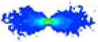
The results from the hyperboloid function are the same as those for the paraboloid, and there is no real number for the ellipse function. So, we could only simulate the PC structure; the resulting image is shown in Fig.
![]()
Figure 5.Image of quadric cone.
Obvious defocusing is also shown in Fig.
Table 5. Optimization of PC Structure
Table 5. Optimization of PC Structure
Before Optimization After Optimization Focal length (mm) 4550 Focal length change (mm) +81.037 Radius of spot (mm) 4.322 Radius of spot (mm) 0.359
![]()
Figure 6.Image of quadric cone after optimization.
![]()
Figure 7.Nested structure of the Wolter-I telescope.
The nested structure is thus designed as shown in Fig.
When the thickness
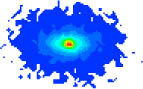
A 10-layer nested CH structure is simulated using Zemax, and the resulting image is shown in Fig.
Under the same nested conditions, the on-axis ideal angular resolution of the Wolter-I (PH) structure telescope is approximately 0.00 arcsec (HPD), and the angular resolution of the conical Wolter-I (CC) telescope is approximately 28.58 arcsec (HPD).
![]()
Figure 8.Image of CH nested structure.
Table
Table 6. Spot Diagrams of Three Types of Nested Structures from Different Fields of View
Table 6. Spot Diagrams of Three Types of Nested Structures from Different Fields of View
FOV (arcmin) PH structure CC structure CH structure 0 


5 


10 

15 


20 

For a conical Wolter-I structure, in a flat focal plane whose axial location is defined by the axial ray focus, the image size (HPD) remains virtually unchanged as a function of the off-axis angle within the mirror’s field of view[
![]()
Figure 9.Changes in angular resolution (HPD) with changes in the field of view.
We set up the same number of incident rays as the different structures. The rays that are collected from the detector are used to describe the geometrical collection area[
![]()
Figure 10.Changes in geometrical collection area with changes in the field of view.
In conclusion, we consider some new Wolter-I-like X ray telescope structures that use one conical mirror and one quadric mirror. After comparing and analyzing these structures, the optimum structure is judged to be the CH structure. The results show that the angular resolution of the CH nested structure is approximately 12.24 arcsec (HPD), which is obviously better than the 28.58 arcsec of the CC nest structure, and images of the CH nested structure are shown from different fields of view. Therefore, the CH nested structure is selected as a reasonable choice to use in the next stage of our research.
[8] S. L. O’Dell, M. C. Weisskopf. Proc. SPIE, 344, 708(1998).
[22] J. E. Koglin, C. M. Hubert Chen, J. C. Chonko, F. E. Christensen, W. W. Craig, T. R. Decker, C. J. Hailey, F. A. Harrison, C. P. Jensen, K. K. Madsen, M. J. Pivovaroff, M. Stern, D. L. Windt, E. Ziegler. Proc. SPIE, 46, 5488(2004).
Tools
Get Citation
Copy Citation Text
Shenghao Chen, Shuang Ma, Zhanshan Wang, "Wolter-I-like X ray telescope structure using one conical mirror and one quadric mirror," Chin. Opt. Lett. 14, 123401 (2016)
Paper Information
Category: X-ray Optics
Received: Sep. 12, 2016
Accepted: Oct. 28, 2016
Published Online: Aug. 2, 2018
The Author Email: Zhanshan Wang (wangzs@tongji.edu.cn)

© Copyright 2018-2021 | Chinese Laser Press.
All Rights Reserved 沪ICP备15018463号-20