


 View fulltext

2024
Volume: 53 Issue 9
12 Article(s)

Guorong ZHU, Chuandong TAN, Yarui XI, Wei YUAN, and Fenglin LIU
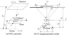
Computed Laminography (CL) technology is well-suited for non-destructive testing of flat objects. Orthogonal Translation CL (OTCL) imaging has the advantages of simple system structure and high resolution in two orthogonal directions, but it also suffers from of incomplete projection data and serious aliasing artifacts in traditional image reconstruction algorithms. Image reconstruction based on prior information can effectively solve the ill-conditioned reconstruction problem caused by missing projection data. This means that, integrating prior information into the incomplete data image reconstruction process can enhance the quality of the reconstructed image. Nevertheless, aligning the prior information with the reconstructed object is crucial, as there is often a deviation between the prior information and the actual detected object. Obtaining accurate prior information requires substantial preprocessing time.To address the issue of aliasing artifacts in OTCL image reconstruction, this paper proposes a reconstruction algorithm based on Self-Prior Information-TV constraint (SPI-TV). The algorithm includes two processes: self-prior information acquisition based on SAA reconstructed images and OTCL image reconstruction based on self-prior-TV constraints. The image reconstruction process includes an iterative step based on its own prior and a TV denoising step based on the Split Bregman (SB) framework. The experimental comparison methods used were SAA, SART and SART-TV. The quality of the reconstructed image was comprehensively evaluated using three sets of quantitative indicators: Root Mean Square Error (RMSE), Universal Quality Index (UQI), and Structural Similarity Index (SSIM). The Peak Signal to Noise Ratio (PSNR) is introduced to evaluate noisy experiments.This paper conducts simulation experiments with noiseless and noisy on the phantom. The results prove that SPI-TV can effectively eliminate aliasing artifacts while suppressing the blur of image edge information and noise. The result is the best performance at the edge of the structure, without toothed contours, and the image contrast and the quality of image reconstruction are high. At the same time, we analyzed the grayscale distribution map. Comparing the grayscale distribution curve of the true image, the reconstruction results of the SART and SART-TV algorithms have obvious jumps in gray values, while the SPI-TV algorithm can better approximate the grayscale curve of the true image, further verifying that performance of the SPI-TV algorithm. For Parallel Translation Computed Laminography (PTCL) scanning, the method used to obtain a priori mask cannot completely obtain the edge information of the reconstructed structure because it only scans in one direction. The prior information is obtained by performing PTCL scanning and OTCL scanning on the phantom (taking the 16th layer as an example). It can be seen that only edge information in a single direction can be obtained from a single segment of scanned data, while the other direction includes interference from adjacent layers. Therefore, the proposed method is suitable for OTCL scanning, and obtaining accurate structural prior information requires vertical scanning data from two sections.Compared with previous image reconstruction methods based on prior information, the proposed method does not require additional information to obtain the prior structure, which greatly reduces the preprocessing time. Both simulation data and actual experiments have verified the effectiveness of the SPI-TV algorithm, which can reduce the impact of noise on reconstructed images while retaining structural edge information, suppress aliasing artifacts, and improve the quality of reconstructed images.
Sep. 25, 2024Vol. 53 Issue 9 0910001 (2024)
Hui LI, Zhengzhou LI, Yuxin YANG, Congyu HAO, and Haitao LIU
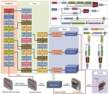
Compared with radar and visible light imaging, infrared imaging has its unique advantages and is widely used in medical imaging, traffic management, automatic driving in the civil field, as well as early warning and air defence systems and naval defence systems in the military field. It has the advantages of good concealment, anti-interference and all-weather operation. In complex backgrounds, small targets are usually submerged and look weak, lacking key information such as shape, colour and texture, generating a large number of spurious false alarms. Traditional methods mainly extract shallow features of the target and background, but due to the lack of effective mining and utilisation of deep features, their adaptability in detecting weak targets in complex scenes is poor, and their ability to detect small targets and their adaptability to the scene need to be improved. Aiming at the problems of low detection performance such as weak signals, unclear features and multiple false alarms of infrared weak targets in complex backgrounds, an infrared weak target detection method based on spanning connection and fusion attention mechanism is proposed. The method combines the attention mechanism with residual networks to extract multiple features of small targets and reduce complex background interference; the bidirectional spanning connection structure fuses feature information at lower and higher levels, highlighting the ability to express the features of weak targets; a high-resolution detection layer is added to regroup the a priori frames of the weak targets and enhance the learning ability of the differences between target and background features; and, finally, the real Gaussian distribution model of target and predicted target frames and calculate their similarity, which solves the problem of sensitivity of target loss regression bias caused by IoU measurements and improves the accuracy of loss regression. The algorithm structure consists of four parts: backbone, neck, head and prediction. The input is an infrared image of size 256×256. The CBS module used by Backbone consists of convolution, batch normalisation and activation functions. The C3 module consists of three convolutional layers and x Resuit modules stitched together. In the last layer of the backbone network, the Convolutional Block Attention Module (CBAM) is introduced, which is fused with the residual network, and the C3CSA module for feature extraction is designed, in order to reduce the background interference in complex scenes. SPPF represents a fast spatial pyramid pooling process. Neck employs a Bidirectional Feature Pyramid Network (BIFPN) that spans connections to fuse low-level detail features to high-level features, as well as transferring high-level semantic information from top to bottom to low-level features. It also adds spanning connections to reduce the loss of some weak target information due to deep feature extraction, to achieve the interaction of global and local information, and to highlight the representation and localisation ability of weak targets at different scales. Upsample represents the up-sampling process. The Head design adds a 64×64 high-resolution feature map weak target detection head, which can avoid the large-scale detection head causing the background interference, and finally predicts the location and confidence information of the target. Comparative tests were conducted on publicly available infrared small target datasets, and the experimental results show that the algorithm has the best performance in detecting infrared small and weak targets in a variety of complex backgrounds, and the average accuracy, recall and speed are significantly improved. The average detection accuracy of this paper's algorithm reaches 98.4%, the model size is only 11.9 MB, and the detection speed is as high as 107 frame/s. By comparing the detection performance of various algorithms in PR curves, ROC curves, and complex scenarios, it can be seen that this paper's algorithm has a better accuracy in detecting weak targets in infrared images in complex scenarios, with a low false alarm rate, and it can be deployed in an embedded terminal for real-time processing.
Sep. 25, 2024Vol. 53 Issue 9 0910002 (2024)
Xiaodong ZHANG, Shuo WANG, Shaoshu GAO, Xinrui WANG, and Long ZHANG
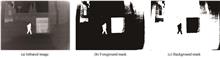
Aiming at the problems of detail weakening and edge blurring in infrared and visible fusion images in low-light scenes, an image fusion method based on information enhancement and mask loss is proposed. Firstly, considering the information degradation of the source image in the low-light scene, the guided filtering is employed to enhance the texture details of the visible image and the edge information of the infrared image before fusion. Secondly, in order to fully extract and effectively fuse the feature information of different modal images, a two-branch network is constructed to extract image features. Based on the dual-branch feature extraction network, an interactive enhancement module based on guided filtering is designed to integrate the complementary information of different feature branches in a progressive interactive way to enhance the detail representation of texture and salient targets in the features. During the fusion stage, an attention guidance module based on spatial and channel dimensions is constructed. In the attention mechanism, the maximum and average scales are used to focus on the feature information. By combining the attention guidance of different dimensions and different scales, the key information in the feature is amplified and the redundant information is filtered out to improve the perceptual capacity of the network for crucial features. In terms of loss function, a method of generating infrared mask is proposed, and a mask loss is designed based on infrared mask to guide the fusion network to retain salient targets, texture details and structure information in the target and background regions. In addition, in the training phase, in order to improve the adaptability of the fusion network and reduce the risk of over-fitting, 1 083 pairs of images in the MSRS dataset are selected for clipping and expansion. The clipping size is 120 × 120, and the moving step size is 120. The obtained 21 660 pairs of image blocks are used as the training data of the model. In the test phase, to comprehensively evaluate the fusion performance of the method, comparative experiments are performed on three public datasets: MSRS, TNO, and LLVIP. This paper selects nine state-of-the-art fusion methods for qualitative comparison, including CNN-based SDNet, GAN-based FusionGAN and GANMcC, AE-based DenseFuse, RFN-Nest, and PIAFusion, visual tasks-based SeaFusion and IRFS, as well as Transformer-based SwinFusion. Five evaluation indexes are selected for quantitative comparison, namely information entropy, spatial frequency, average gradient, standard deviation, and visual fidelity. The experimental results show that the proposed method is superior to other comparison algorithms in both qualitative and quantitative evaluation on three public datasets. The generated fusion image exhibits rich texture details, clear saliency targets, and excellent visual perception. Finally, in order to verify the effectiveness of the proposed module, ablation experiments are conducted on the image pre-enhancement processing, interactive enhancement module, mask loss and attention guidance module, respectively. The qualitative and quantitative comparison results of the ablation experiments confirm the effectiveness of the proposed module in the fusion algorithm.
Sep. 25, 2024Vol. 53 Issue 9 0910003 (2024)
Yilong ZHANG, Shengming ZHU, Haixia WANG, Haohao SUN, and Rui YAN
Traditional fingerprint recognition systems rely on external fingerprints, which face significant limitations due to environmental factors like scratches, water stains, and wear that degrade image quality and recognition performance. Additionally, external fingerprints are vulnerable to forgery using materials like silicone, leading to security concerns. In contrast, internal fingerprints, which are the source of external fingerprints, are more resistant to interference, less affected by external damage, and much harder to forge due to their location beneath the skin, offering enhanced security for fingerprint recognition systems. Optical Coherence Tomorgraphy (OCT) has been applied for fingertip volume data acquisition, which contains internal and external fingerprints. Currently, OCT-based internal and external fingerprint extraction algorithms mainly fall into two categories: the En-Face method and the tissue contour extraction method. The En-Face method accumulates the grayscale information of the stratum corneum layer and viable epidermal layer regions in the OCT axial slice (B-scan) images, generating internal and external fingerprint images based on the grayscale differences within the layer region. However, this type of methods are inevitably affected by noise and individual differences, thus affecting the quality and performance of the generated fingerprints. Besides, it offers fast generation speed without requiring complex preprocessing and postprocessing. On the other hand, the tissue contour extraction method determines the positions of the the stratum corneum layer contour and viable epidermal layer contour in the B-scan images and utilizes the grayscale differences around the contour to generate internal and external fingerprint images. Its advantage lies in its ability to generate high-quality fingerprints with good performance if the contours of the stratum corneum layer and viable epidermal layer are accurately fitted. However, it heavily depends on the accuracy of contour extraction, and inaccurate extraction may lead to incomplete fingerprint ridge and valley information, thereby affecting fingerprint quality and performance, and requiring complex preprocessing and postprocessing steps. Combining the ideas of the En-Face method and contour method, this paper proposes a method for OCT internal and external fingerprint extraction based on Soft Label and Coordinate attention U-Net, referred to as the SLCA-UNet method. Firstly, during the annotation process, based on manually annotated stratum corneum and viable epidermal layer contour position, a polynomial curve traversing the contour is fitted. Using this curve as a reference, Gaussian functions are employed to assign different weights to pixels around the curve, ensuring that pixels closer to the contour center have higher probability weights. After annotating the data, a U-Net network and KL loss function are utilized to learn this probability distribution. Secondly, this paper incorporates a coordinate attention module into the U-Net network structure, enabling it to focus on global features of B-scan images without introducing excessive time overhead. This module helps to focus on the positions of the stratum corneum layer region and viable epidermal layer region, better allocating different probabilities to pixels in each tissue layer. Finally, based on the probability distribution results predicted by the network and the grayscale information of the original image, internal and external fingerprint images are generated. This method not only considers the weights of the contour center and surrounding pixels but also reduces the influence of noise and errors, thereby reducing the algorithm's dependency on contour accuracy. Through a series of experiments, this paper demonstrates that the proposed method can indeed improve the quality and performance of generated fingerprints. Experimental results show that our method can extract internal and external fingerprint images from 3D fingerprint volume data of size 1 400×1 800×500 within 140 seconds. Moreover, in a database of 1 280 fingerprint groups, the mean NFIQ 2.0 score for external fingerprints is 35, with an EER matching score of 0.8%, while the mean NFIQ 2.0 score for internal fingerprints is 47, with an EER matching score of 0.8%. The proposed method not only has a short processing time but also exhibits excellent performance and quality.
Sep. 25, 2024Vol. 53 Issue 9 0910004 (2024)
Wei WANG, Haiyu ZHANG, Lianbao KE, Qing KANG, Jianjun LI, and Hai BI
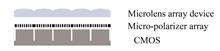
The Division of Focal-plane Polarimeter camera (DoFP) has unique advantages such as small size, high integration, and strong real-time performance, and is widely used in the field of defect detection. The core components of a division of focal-plane polarimeter camera consist of a Complementary Metal Oxide Semiconductor Photodetector (CMOS), a micro-polarizer array, and a micro lens array device. The division of focal-plane polarimeter camera integrates photodetectors and micro polarizer devices on the same focal plane. By placing a photolithography metal grating linear polarizer array at the front end of a pixel, information acquisition corresponding to one linear polarization direction is achieved for each pixel. Therefore, one frame of imaging can complete the detection of energy in multiple polarization directions. To meet the application requirements of defect detection, it is necessary to ensure the imaging quality of division of focal-plane polarimeter cameras. According to the previous theoretical analysis, the key factors affecting imaging quality are mainly the polarization azimuth deviation of each imaging unit and the non-uniformity of the response of each imaging unit, among which the non-uniformity of response is mainly manifested as the non-uniformity of transmittance. This paper introduces the Stokes model, and establishes a polarization response model for division of focal-plane polarimeter camera cameras. We focused on analyzing the impact of angle errors in relative transmittance and polarization azimuth angle on the measurement polarization error of division of focal-plane polarimeter camera cameras by using the method of calculating partial derivatives. We also analyzed the trend of the measurement polarization error changing with the polarization degree and polarization angle of the incident light. A polarization azimuth measurement system was established to measure the four polarization azimuth angles of a micro polarization array. The system uses an integrating sphere and a rotating polarizer as the standard radiation source, with the rotating polarizer as the reference polarizer installed on a one-dimensional precision rotating table, so that linearly polarized light in different polarization directions can be obtained by rotating the polarizer. Polarization cameras collect incident light at different polarization angles, and obtain the polarization azimuth angle of the polarization camera micro polarization array through Malus's model fitting model, thereby achieving calibration of the polarization azimuth angle. The relative transmittance was measured using an integrating sphere reference light source. The response values of different polarization azimuth angles were measured at different integration times, which are the mean of the polarization directions corresponding to all super-pixels. The complete polarization response value was calculated based on the equivalent extinction ratio, and the ratio of complete polarization response values for P1~P3 and P4 was calculated. After eliminating the influence of extinction ratio, calculate the relative transmittance of P1~P4, with relative transmittance values of 0.965, 1.000, 1.010, and 1.000, respectively. Finally, the measurement polarization degree was calculated based on the polarization response model, as well as the relative transmittance and polarization azimuth test results. In order to verify the calibration effect, the polarization measurement results of incident light with different polarization angles were calculated. The response value used for calculation here is the mean of the polarization direction corresponding to all super-pixels. The light generated by the combination of an integrating sphere light source and a standard polarizer is used as the incident light for verifying the polarization accuracy of a polarization camera, and the outgoing light can be approximated as perfectly linearly polarized light. Verify the measurement accuracy of division of focal-plane polarimeter camera by rotating the standard polarizer at an interval of 10° and 180°. The measurement results show that the average measurement result of polarization degree before calibration is 0.964 4, with a relative standard deviation of 1.02%. After calibration, the average measurement result of polarization degree is 0.998 9, with a relative standard deviation of 0.44%. The experimental results show that the detection scheme can calibrate the performance of the division of focal-plane polarimeter camera with high calibration accuracy, laying the foundation for the high-precision application of division of focal-plane polarimeter camera.
Sep. 25, 2024Vol. 53 Issue 9 0911002 (2024)
Xin WU, Baoteng XU, Jialin LIU, Wei ZHOU, and Xibin YANG
In recent years, multispectral filter array sensors have received increasing attention as a method capable of simultaneously capturing high-quality and alignment-free images in multiple bands during a single acquisition. An important development in this direction is the sensor that simultaneously captures short-wave infrared (NIR) and color (RGB) images, called RGB-NIR sensor. Cameras using RGB-NIR sensors can easily obtain aligned RGB and NIR images at the same time and can be used for a variety of optical applications. RGB-NIR sensors face more challenges in areas such as demosaicing than regular RGB sensor array (Bayer array) sensors. There are no mature commercial image signal processing solutions on the market specifically for RGB-NIR sensors. The number of channels and the arrangement law of RGB-NIR sensor filter arrays are different from traditional RGB sensor arrays, so how to demosaic RGB-NIR sensors is a key issue. Among the existing RGB-NIR array demosaicing algorithms, the residual interpolation-based algorithm is versatile and perform well, and the computational cost is low. However, the regularization parameter of the standard guide filtering architecture is fixed, which leads to easy artifacts at the edges or textures of the image. And the residual interpolation-based algorithm use the standard guide filtering architecture, so the above problems inevitably occur. To address the above situation, this paper proposes a weighted guide filtering demosaicing algorithm that introduces weighting coefficients. The proposed demosaicing algorithm first obtains the G-channel image using gradient based threshold free algorithm combined with residual interpolation algorithm. Then the images of R, B, and IR channels are interpolated by weighted guide filtering. The linear coefficients are no longer simply determined by using the average value, but the weighting coefficients are introduced and calculated by the weighted average method. Finally, residual interpolation is applied to obtain the final image. To validate the algorithm, it was tested on a dataset as well as on real devices, respectively. For the dataset experiment, the TokyoTech dataset, which is currently the most commonly used dataset for RGB-NIR multispectral imaging, was selected for testing; for the real device experiment, a specific RGB-NIR sensor (OV2744 sensor) was used to build the image acquisition system. Finally, the RGB-NIR sensor camera was also compared with the common RGB sensor camera to explore the application scenarios of the RGB-NIR sensor camera. For the test experiment on the dataset, PSNR (Peak Signal To Noise Ratio) is selected as the evaluation metrics. The PSNR and the average PSNR of the four algorithms for the dataset of 16 images shown that the algorithm proposed in this paper has the best performance. The proposed algorithm reduces the artifacts at the edges. For experiments on real devices, the NIQE (Natural Image Quality Evaluator) metrics was taken to evaluate the results of the algorithm. The experimental results are shown when both white light source and infrared light source are turned on. The interpolation effect of the algorithm proposed in this paper is the best, and the average NIQE values of 5.54 and 3.77 are the smallest for both color images and infrared images, respectively. The same scene was taken again with the IR light source turned off. Without infrared light, the algorithm of this paper also performs optimally on both color and infrared images, with the average NIQE values of 5.33 and 4.56, respectively. Moreover, the proposed algorithm also has better robustness and the quality of the obtained images is more stable. Finally, it can be seen in the experiment comparing with the ordinary RGB sensor that the images obtained by the RGB-NIR sensor can clearly see the contents of the shadow region and effectively remove the shadows. Aiming at the problems of existing demosaicing algorithms for RGB-NIR sensors, this paper proposes a residual interpolation demosaicing algorithm based on weighted guide filtering, and experiments are carried out on both publicly available dataset as well as practical device application. From the experimental results, it can be seen that the algorithm proposed in this paper has the best performance compared with other algorithms. Both in the dataset and in the real device application, there is a significant improvement in the metrics, and the artifacts at the edges can be better reduced in the subjective vision. Meanwhile, the proposed algorithm has better robustness and more stable image quality. Finally, the application of RGB-NIR sensors on the application scenario of shadow removal is also explored. From the result, it can be seen that the RGB-NIR sensor image acquisition system can provide a significant shadow removal effect.
Sep. 25, 2024Vol. 53 Issue 9 0911003 (2024)

Lu NIE, Xiangjun LI, Zihao WANG, Wenxiao SUN, and Jie SUN
Although terahertz (THz) spectroscopy exhibits great application prospects in the fields of biomedicine and security detection, conventional sensing schemes face unavoidable limitations in the analysis of trace-amount samples. In this paper, a terahertz absorption spectrum boosting method based on the two-dimensional stretchable metagrating structures is proposed to improve the interaction between the terahertz wave and the trace-amount samples. Based on Guided-mode Resonance (GMR) effect, the local electric field in a thin-film sample can be enhanced by simultaneously varying the periodic length P of PDMS substrate and nano-Ag reflective layer, so that wideband terahertz absorption spectra can be greatly enhanced. This strategies for utilizing reflective layers exhibits a great absorption enhancement factor, of about 111 times, in a wideband terahertz frequency range, facilitating the identification of different trace-amount analytes, such as thin α-lactose films. The proposed method provides a new, to the best of our knowledge, choice for the enhancement of ultra-wide terahertz absorption spectra, and paves the way for the detection of trace-amount chemical, biomedical, or organic materials in the terahertz regime.Terahertz absorption spectroscopy enables many new potential applications, and demonstrates great promise in molecular fingerprint detection. THz detection is nondestructive, and many complex molecules have feature absorption resonance peaks in the THz spectral frequency range; according to molecular rotational and vibrational modes. However, traditional detection modes for identifying the fingerprint spectrum of trace-amount samples usually use more sample materials because of the diffraction of the THz. The response between waves and matter is also very weak. In order to improve the detection capability of trace-amount analytes, an effective strengthening strategy is to introduce additional resonance micro-structures to enhance the interaction between waves and matter. In this study, we introduce a two-dimensional stretchable metagrating periodic structures with reflection mode by numerical simulation. Compared with other methods, the proposed scheme provides three main advantages, as follows: 1) a great broadband trace-mount terahertz absorption enhancement factor can be realized based on reflection mode supported by nano-Ag reflective layer, providing the advantages of simple design, only the reflection spectra needs to be measured, greatly reducing the workload, and easy adjustment of the absorption enhancement range; 2) the enhanced absorption spectra can be built by connecting a series of resonant peaks of fixed incident terahertz waves obtained by changing the stretch factor S; 3) absorption enhancement factors of about 111 times can be achieved numerically in an ultra-broadband terahertz band for 0.2 μm thick lactose analytes, enabling the explicit identification of various analytes, such as trace-amount thin film samples.Firstly, the structural schematic the numerical analysis method, the principle of generating resonance peaks, and the problem of stretching substrate deformation are given in succession in section 1. In the second part, the enhancement factors based on the GMR model generation, Lorentzian model of lactose, and the electric field distributions of metagrating structure at the x-y plane around 0.53 THz with and without the thick lactose are illustrated in order. Finally, we get the optimal values by systematically scanning various parameters, including the thickness t of the lactose film (ranging from 0.2 to 1.0 μm in a step of 0.2 μm), the thickness h1of the PE bar (ranging from 55 to 95 μm in a step of 10 μm), and the width of the PE bar (ranging from 140 to 180 μm in a step of 10 μm). The optimal conditions considered are: coated lactose thicknesses t=0.2 μm, PE bar thickness h1=55 μm, and PE bar width W=180 μm. The proposed absorption enhancement strategy for thin samples is relatively easy to manufacture and measure, which paves a new way for future high-performance terahertz fingerprint detection with two-dimensional stretchable metagrating structures.
Sep. 25, 2024Vol. 53 Issue 9 0913001 (2024)
Qingyu CONG, Zhaoyi LI, Jingjie ZHOU, Zuowen FAN, Lianxi JIA, and Ting HU
Silicon nitride, a semiconductor material compatible with the CMOS process, offers numerous advantages such as a wide transparent window, a larger bandgap, non-existent two-photon absorption, and a smaller thermo-optic coefficient compared to silicon. These features have garnered significant attention in the field of silicon photonics. Among various silicon nitride deposition processes, those utilizing low-pressure chemical vapor deposition methods to create silicon nitride waveguides benefit from high film density stability, lower absorption loss, and reproducible processes. However, due to high process temperatures, the depsition of silicon nitride films exceeding 400 nm in thickness on 8-inch wafers results in induced tensile stress, leading to film cracking.In this study, a photonic Damascene process was used to fabricate low-loss silicon nitride photonic devices. Oxygen-buried layers are first deposited in two steps, which facilitates the formation of a dense oxide layer. We etched the pattern on the buried oxide with depth around 900 nm, following the depostion. The deposition process involves a two-step approach. In the first step, a 400 nm silicon nitride film is deposited, followed by Chemical Mechanical Polishing (CMP) to remove excess silicon nitride from the surface, thereby reducing stress accumulation. In the second step, an additional layer of silicon nitride is deposited, followed by a second CMP. After the completion of silicon nitride deposition, a high-temperature anneal is performed to break the Si-H and N-H bonds in the film, helping to reduce absorption losses in the waveguide core layer. Finally, a 2.6 μm silicon dioxide layer is deposited as the top cladding layer using Plasma-Enhanced Chemical Vapor Deposition (PECVD). To relieve stress and prevent crack propagation, a 5 μm×5 μm checkerboard structure was designed.The single mode condition of the 800 nm silicon nitride waveguide was analyzed by Lumerical software, and the waveguide width of 0.8 μm was selected to satisfy the single mode condition of TE0 and TM0. Based on the simulated single-mode condition, the Finite-Difference Time-Domain (FDTD) simulation module was used to simulate the bending loss of the 0.8 μm wide silicon nitride waveguide. The bending loss is 0.010 462 dB per 90° bend at a bending radius of 50 μm and 0.006 302 dB per 90° bend at a bending radius of 80 μm.We designed several sets of silicon nitride waveguide structures with different lengths and different numbers of bendings to test the propagation loss and bending loss of silicon nitride waveguides. The results show that the propagation loss is 0.087 dB/cm at 1 550 nm and 0.062 dB/cm at 1 580 nm, which are among the best in the field. The bending loss is 0.006 5 dB per 90° bend at a bending radius of 50 μm and 0.006 dB per 90° bend at a bending radius of 80 μm. Waveguides at different locations on the wafer were also tested and the waveguide porpagation loss remained within (0.096±0.009 2) dB/cm over the entire wafer. In this paper, an edge coupler was used to couple to the input light and a coupler with a coupling loss of 0.51 dB was designed by scanning the length and tip width of the edge coupler.In this study, low-loss thick silicon nitride waveguides were successfully fabricated on an 8-inch wafer. It was observed that annealing the core layer had the most significant effect on reducing the propagation loss of the waveguide, with the loss decreasing progressively with annealing temperature and time increased. The silicon nitride waveguides produced using the developed process exhibited excellent uniformity across the wafer with minimal variation, while maintaining extremely low propagation loss. The process can be integrated with other process platforms to expand its applications in nonlinear optics, narrow linewidth lasers, radar ranging, and other areas.
Sep. 25, 2024Vol. 53 Issue 9 0913002 (2024)
Lijuan ZHAO, Zimeng HUANG, and Zhiniu XU
Distributed Brillouin fiber sensing technology enables continuous spatial measurement of parameters such as temperature and pressure, offering advantages over traditional point sensors in terms of wide range, long distance, and high capacity. Civil structures and large machinery inevitably face lateral pressures due to their own weight and external impacts during construction and use, necessitating reliable and efficient sensors for these forces. Additionally, temperature is a crucial physical parameter that often needs to be measured simultaneously with pressure. The use of Brillouin frequency shift in fiber optic distributed sensing for temperature or pressure is common, but its sensitivity to both parameters simultaneously complicates the measurement of multiple variables at once. Hence, this paper introduces a simultaneous demodulation method for temperature, fast-axis pressure, and slow-axis pressure. The numerical simulation and emulation were performed using the wave optics and solid mechanics modules within the COMSOL Multiphysics finite element analysis software. After setting the boundary conditions, pressure was applied to the photonic crystal fiber, and its deformation under pressure was calculated. The effective refractive index of the fiber was calculated using the wave optics module. By substituting into formulas, the birefringence frequency shift, Brillouin frequency shift, and Brillouin linewidth resulting from deformation were obtained. Demodulation was then employed to acquire the specific values of these three variables. To validate the reliability of the demodulation results, lateral pressure is applied to both the fast and slow axes, while simultaneously altering the temperature. Using the birefringence frequency shift, Brillouin frequency shift, and Brillouin linewidth at 0 MPa and 0 ℃ as reference values, simulations determined the variations in these parameters under different pressures or temperatures. These variations are then substituted into formulas to calculate ?P1', ?P2', and ?T'. By comparing these calculated values with the actual applied values of ?P1, ?P2, and ?T, the corresponding error values can be ascertained. The results indicate that the three parameters can be simultaneously demodulated with demodulation errors within 1 MPa and 1 ℃. The mean errors for fast-axis pressure, slow-axis pressure, and temperature were 0.21 MPa, 0.31 MPa, and 0.30 ℃, respectively, with standard deviations of 0.15 MPa, 0.21 MPa, and 0.21 ℃, respectively. When lateral pressures of 0 to 30 MPa and temperatures of 0 to 100 ℃ were applied, the pressure sensitivity in the fast-axis direction of the photonic crystal fiber was approximately -1.961 GHz/MPa, the pressure sensitivity in the slow-axis direction was about 1.356 GHz/MPa, and its temperature sensitivity was around 0.105 MHz/℃. Compared with the current optimal structure of the photonic crystal fiber, the pressure sensitivity is improved by -957 MHz/MPa. This paper presents a highly sensitive polarization-maintaining photonic crystal fiber that enables simultaneous demodulation of temperature, fast axis pressure, and slow axis pressure. Due to the sensitivity of the polarization-maintaining fiber to temperature, fast axis pressure, and slow axis pressure, this technology can be applied to the detection of high-precision fiber optic gyroscope rings. The proposed sensor and demodulation method offer significant reference value for the distributed monitoring of temperature and pressure in different directions during the construction and use of civil structures and large machinery.
Sep. 25, 2024Vol. 53 Issue 9 0906001 (2024)
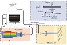
Peiming WANG, Youlong YU, Yi YU, Bin LIU, and Kexin MIAO
Amid the rapid advancements in optical fiber communications and sensing technologies, polarization-maintaining fibers have increasingly been utilized in fiber sensing systems. As a novel type of polarization-maintaining fiber, Side-Hole Fiber (SHF), with its unique microstructure and superior performance, holds broad application prospects in fields such as communication, sensing, and medical technology. The sensors made from SHF are highly sensitive, capable of monitoring multiple parameters simultaneously, and are easily integrated into the materials being measured. They play an extremely important role in the field of structural health monitoring, thereby attracting widespread attention. In recent years, many researchers have studied and analyzed the structure and birefringence properties of SHF. However, systematic analysis and research on the impact of pressure on the birefringence performance of SHF have not been reported.In this paper, the impact of radial pressure on the birefringence characteristics of SHF was analyzed systematically based on coupled mode theory and the photoelastic effect. To facilitate the experimental component of the study, a mechanical loading apparatus was engineered to apply varying levels of radial pressure on the SHF using different weights. Furthermore, we established an experimental system grounded in the principle of polarization interference, designed specifically to measure the birefringence of SHF under different pressure conditions. The experimental setup comprised a broadband light source, a polarizer, the SHF under test, and a spectrometer. Light from the broadband source, after passing through the polarizer, was transmitted through the SHF. The interference spectrum was subsequently captured by the spectrometer. Birefringence was quantified by analyzing the mean wavelength of troughs and the average interval between adjacent peaks within the interference spectrum.Experimental results indicated that while keeping the pressure magnitude constant, the birefringence values varied according to a cosine function with respect to the direction of application, achieving maximum and minimum values at even and odd multiples of π/2, respectively. When the direction of application was held constant, the birefringence values exhibited a linear relationship with the magnitude of pressure. Specifically, for angles θ within the range (kπ-π/4,kπ+π/4)(where k is an integer), birefringence values increased linearly with pressure. Conversely, for θ in the range (kπ+π/4,kπ+3π/4), birefringence values decreased linearly with pressure. At θ=kπ+π/4 the birefringence values remained essentially unchanged. The correlation coefficient r between the experimental and simulation results was 0.992 2, indicating a high degree of consistency within the permissible error range.
Sep. 25, 2024Vol. 53 Issue 9 0906002 (2024)
Yilun LIU, Penghua XUAN, Yansong LI, Yuanchang RAN, and Qiwei WANG
The intrinsic signal stability is an important performance parameter for long-term stable operation and high-precision measurement in optical current sensing. If the intrinsic signal exhibits fluctuations, drift, or jitter, it can lead to cumulative measurement errors and increased instability in the system. This can result in incorrect current measurement values, misjudgment, and misleading system operation status assessment, thereby affecting the stability and safety of the system. Therefore, ensuring the stability of the intrinsic signal is crucial for maintaining long-term stability in optical current sensing systems.Jitter in the intrinsic signal has a direct negative impact on the measurement accuracy of optical current sensing systems. Jitter introduces fluctuations in the instantaneous signal values, leading to instability and inaccuracy in the measurement results. Particularly in applications requiring high-precision current measurements, the presence of intrinsic signal jitter introduces additional errors, reducing the measurement accuracy and reliability of the system. Currently, conventional methods such as dual-path techniques can not eliminate jitter in the intrinsic signal effectively. Despite the use of dual-path techniques, the intrinsic signal is still influenced by factors such as optical components, circuit noise, and environmental interference, and the jitter can not be completely eliminated. To address the issue of intrinsic signal jitter in optical current sensing systems and improve measurement accuracy, a debouncing Kalman-based method for high-precision extraction of the intrinsic signal is proposed. This method involves a detailed analysis of the noise characteristics and optical path structure of the optical current sensing system, followed by the establishment of a mathematical model for the intrinsic signal. Subsequently, a debouncing function is introduced to modify the Kalman gain K, resulting in a Debouncing Kalman (DBKalgorithm. The debouncing Kalman algorithm aims to address the severe estimation jitter in the state estimates caused by the initial state dependence and measurement process uncertainty sensitivity of the standard Kalman gain K.In this method, the debouncing Kalman filtering algorithm utilizes the debouncing function to modify the Kalman gain K, thereby providing denoising processing for the intrinsic signal. The introduction of the debouncing function allows the Kalman filtering algorithm to better adapt to the jitter characteristics of the intrinsic signal, reducing the impact of jitter on state estimation. Compared to traditional Kalman filtering algorithms, the debouncing Kalman filtering algorithm exhibits greater stability in the state estimation process and can effectively extract high-precision estimates of the intrinsic signal. Additionally, a recursive estimation of the noise variance is introduced to ensure real-time correction of the noise variance during the filtering process.The debouncing Kalman algorithm was validated and compared with the standard Kalman algorithm through simulations in MATLAB. The simulation results show that, under the same set of parameters, the relative error of the standard Kalman algorithm reaches approximately 11% after convergence, while the debouncing Kalman algorithm achievs a relative error of approximately 2% after convergence. This validates the feasibility of the proposed algorithm. Furthermore, the stability of the algorithm was derived and verified using the Lyapunov stability analysis method. Finally, an optical current sensing experimental platform was constructed, and the proposed algorithm was implemented in parallel on the LabVIEW FPGA hardware platform. The experimental results demonstrate that the amplitude error of the filtered intrinsic component is within 2%. This verifies the real-time performance of the algorithm and its ability to meet practical engineering requirements. The successful construction of the experimental platform and the parallel implementation of the algorithm on the hardware platform further demonstrate the real-time capability and feasibility of the proposed algorithm. It provides strong support for practical applications in the field of optical current sensing and offers a high-precision and stable solution to current measurement problems in engineering practice.
Sep. 25, 2024Vol. 53 Issue 9 0906003 (2024)
Zhengzhong HUANG, and Liangcai CAO
In 1948, GABOR D proposed the concept of holography, which provided a pioneering technical solution for the quantitative analysis of light-wave fields. After more than 70 years of development, computational imaging and quantitative phase imaging based on holography has become an important tool for the quantitative measurement of the light-wave field. It provides a new observation dimension for the fields of physics, biology and materials science, and builds a bridge of optical imaging and light scattering. It breaks through the physical limitations of conventional optical imaging systems. It plays a crucial role in the pathological study of diseases and the characterization of materials. From the point of signal analysis, the process of holographic recording and reconstruction can be regarded as the transformation between the complex domain and the real domain. The mathematical principle and physical realization of digital holography are discussed. In addition, the new challenges of holographic imaging are summarized in the prospects.The propagation of wavefront is described by the complex-amplitude distribution. The idea of digitally reconstructing the optical wavefront first appeared in the 1960 s. However, there was array-detector-based holographic imaging for applications until the 1990 s. At that time, two sectors of technology have been important developments. One of which is that microtechnological processes have resulted in CCD arrays with sufficiently small pixels to fulfill the Shannon condition, which is suitable for the spatial sampling of an optical wavefront. The other is that the computational treatment of images has become accessible largely, which has benefited from the significant improvement in microprocessor performance, in particular their processing units as well as storage capacities. Due to the high-frequency oscillation of visible light wavefront, Conventional optical detectors only respond to the intensity or amplitude of the incident light. Only the intensity-value measurement in the real-domain can be recorded by the camera from the mathematics. Holographic imaging becomes the necessary link with the help of additional optical configurations and computational algorithms. After decades of development, multiple branches were multiplied with the simultaneous development of optical measurement technology and computer technology. The development of holographic imaging has been discussed in the context of these solutions, focusing on the principal approaches that have had a significant impact on modern holographic methods and applications: digital holography, optical diffraction tomography, phase shifting interference, phase retrieval, holographic multiplexing, multiple model and deep learning.Interference technology has played an important role in the field of optical measurement. By introducing the reference wave, the invisible phase information is transformed into the interference fringe distribution. A series of fringe analysis and reconstruction algorithms are used to demodulate the phase from the interferogram. The most classic fringe analysis is phase-shifting interferometry. When the interference angle of the reference wave becomes large, the interference fringe is equivalent to the high-frequency carrier, and the object information is encoded into the high spatial frequency domain. The complex amplitude of the object can be extracted, which is the mainstream method of holographic imaging. The spatial frequency distribution of the image is 2D, which can introduce interference in different spatial directions, thus inspiring the birth of holographic multiplexing.Different from interferometry, another series of methods is based on wave diffraction with non-interferometry. the intensity distribution of the diffraction field of the object is recorded, then the complex-amplitude of the object is reconstructed from the diffraction field. This process can be considered as a mathematical inverse problem, that is phase retrieval. The advantage of non-interferometry is that it can further simplify the optical system, and transform the “burden” of the configuration to the calculation. With the development of computer processing power, deep neural networks have become a research hotspot in solving inverse problems in imaging. The diffraction intensity is associated with the measured wavefront through numerical diffraction with neural networks, which can replace traditional holography to achieve functions such as digital focusing, phase unwrapping, and label-free virtual dyeing.Thanks to the advancements in detecting devices, laser sources, and computing powers, there have been experimentally significant technical advances in holographic imaging. The applications have been expanded to various fields, from biophysics, cell biology, hematology, to infectious diseases.
Sep. 25, 2024Vol. 53 Issue 9 0911001 (2024)
© Copyright 2018-2021 | Chinese Laser Press.
All Rights Reserved 沪ICP备15018463号-20