


Please enter the answer below before you can view the full text.
5+2=

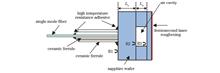
ObjectivePressure monitoring in high-temperature environments is necessary for aerospace, chemical smelting, and petroleum power. Optical fiber sensors can be applied in the measurement of various parameters under high-temperature and harsh environment due to their advantages of passivity, anti-electromagnetic interference, high-temperature resistance, and compactness. The optimal technical approach for pressure measurement is the optical fiber extrinsic Fabry-Pérot interferometer (EFPI), which includes two typical structures of diaphragm-based type and diaphragm-free type. The principle of the diaphragm-free type is that as the refractive index of the gas in the open cavity changes linearly with the ambient pressure, diaphragm-free optical fiber pressure sensors can only measure the gas pressure, and its sensitivity is greatly affected by temperature. The diaphragm-type optical fiber EFPI pressure sensor based on different materials has been widely employed in pressure measurement. The working temperature of the sensor is mainly determined by the material of pressure sensing films. For example, the EFPI pressure sensor based on silicon dioxide is limited by the softening of the glass diaphragm at high temperature, and the working temperature for a long time is generally lower than 800 ℃. With a melting point of 2045 ℃ and a wide transmission spectral range, sapphire is an ideal material for developing ultra-high temperature optical fiber sensors. To measure pressure in high-temperature and harsh environment, we propose and experimentally demonstrate a sapphire Fabry-Pérot (F-P) interferometer with high temperature and large pressure range. The sensor is fabricated by direct bonding of three-layer sapphire wafers, including the sapphire substrate, the sapphire wafer with a through hole, and pressure-sensitive sapphire wafer.MethodsFirstly, a femtosecond laser is adopted to slice the sapphire wafer. The sapphire wafer is fixed on the six-dimensional micro-motion platform, and the laser power is adjusted to 30 mW through the attenuator. The laser beam is vertically focused on the surface of the sapphire wafer through a plano-convex lens with a focal length of 100 mm. The laser is scanned on the sapphire wafer at 5 mm intervals by controlling the six-dimensional micro-motion platform. Secondly, a through hole is inscribed on a sapphire wafer with a thickness of 175 μm. The laser power is adjusted to 5 mW, and the laser beam is focused by a 20× objective lens. The laser scans in the center of the sapphire wafer until the inner wafer falls off automatically. Thirdly, the outer surface of the sapphire diaphragm is roughened. The laser power is adjusted to 1 mW to roughen the diaphragm without changing the thickness of the diaphragm as much as possible. The laser scans the surface by line-by-line method with a spacing of 50 μm. Finally, to improve the stability of the sensor at high temperature and high pressure, the direct bonding process of sapphire wafers is designed. After RCA cleaning, sapphire wafers are immersed in 85% (mass fraction) H3PO4 solution to remove residual oxides on the surface. Then wafers are immersed in a H2SO4 diluted solution to deposit a hydrophilic layer. The wafer pair is successfully bonded after being kept at 1300 ℃ for 20 h and pressure test systems are set up to investigate the pressure response of the proposed sensor.Results and DiscussionsThe EFPI interference signal collected by the white light interference demodulator with a center wavelength of 1550 nm is shown in Fig. 4(a), and its frequency spectrum is shown in Fig. 4(b). The reflection spectrum is formed by three-beam interference. The second peak is the F-P signal formed by two surfaces (R1, R2) of the sapphire substrate, which is utilized to measure the temperature. The third peak is the F-P signal formed by the front surface of the sapphire substrate and the front surface of the pressure-sensing sapphire diaphragm (R1, R3), which is leveraged to measure the pressure. The main frequency signal is extracted by the Gaussian window function, and the interference signals of the two cavities are obtained by inverse Fourier transform. The optical cavity length can be calculated by demodulating the phase information of the interference signal. The ultra-high pressure test shows that the pressure sensitivity of the sensor is 0.1253 μm/MPa within the pressure range of 0-30 MPa, and the sensor has no leakage at 45 MPa. As the temperature increases, the sensitivity of the sensor increases slightly, reaching 0.1322 μm/MPa at 700 ℃. Figure 9 shows that the measurement resolution of the optical cavity length is about 1.5 nm. Combined with the pressure sensitivity of the sensor at room temperature, the pressure resolution of the ultra-high pressure measuring system is 12 kPa, and the relative resolution is 0.04% FS (full scale).ConclusionsIn this study, an optical fiber pressure sensor based on sapphire wafers processed by femtosecond laser is proposed. Sapphire wafers with through holes and rough sapphire pressure-sensitive wafers are fabricated by femtosecond laser micromachining. The experimental results show that the sensor can measure the pressure within the temperature range of 25-700 ℃ and the wide pressure range of 0-30 MPa, and the sensor does not break and leak under the ultra-high pressure of 45 MPa. The sensor is resistant to ultra-high pressure, high temperature, and intrinsic safety, which can solve the technical problems of pressure in-situ testing in the harsh environment of high temperature and high pressure.
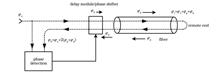
ObjectiveThe antenna array technology overcomes the aperture limitation of single antenna detection and improves the microwave detection capability by several or even dozens of times, which is regarded as a revolutionary change in microwave detection technology. Stable transmission of optically carried microwave signals via fiber links enables the long-distance distribution of microwave signals with delay (or phase) stability required in antenna arrays and plays an irreplaceable role in the new generation of microwave measurement technology with multiple antenna coordination. The core issue of this stable transmission technology is the unstable transmission delay due to environmental factors such as temperature variation and physical vibration. The key to this technology lies in how to accurately measure and compensate for the fiber transmission delay variation, thereby ensuring the delay or phase stability of the signal transmitted to the remote end.MethodsIncreasing the signal frequency not only improves the measurement accuracy of transmission delay but also weakens the effect of other sources of noise. Therefore, transmission stability can be improved by increasing the signal frequency (Fig. 2). To achieve stable transmission, it is necessary to first detect the phase variation of the high-frequency signal with high sensitivity. Therefore, we propose a phase detection method by dual optical and electrical heterodyne mixing (Fig. 3). The RF signal to be transmitted at the local end after electrical frequency shifting is modulated onto an optical carrier to generate a reference. It is then optically mixed with the signal returned to the local end after optical frequency shifting at the remote end. The resulting intermediate frequency signals are then obtained through a low-speed photodiode. Finally, the two intermediate frequency signals are mixed electrically to obtain the phase variation of the returned signal representing the transmission delay variation. This method significantly improves receiving sensitivity and phase detection precision. High-precision control of the phase of high-frequency microwave signals or the optical delay is another key technique to be addressed for stable transmission. To improve the phase control precision of microwave signals in stable-phase transmission, we put forward a high-frequency signal phase control method based on single-sideband modulation. By adding the phase of the MHz-level intermediate frequency signal to the high-frequency signal via single-sideband modulation, accurate phase control of the high-frequency signal can be achieved by controlling the intermediate frequency signal. To achieve high-precision control of optical delay in stable-time transmission, we adopt a cascaded optical delay control method. This method employs a high-precision (fs-level), small-range (ps-level) piezoelectric fiber stretcher and a medium-precision (ps-level), large-range (ns-level) motorized adjustable delay line in series, achieving remarkable performance in delay compensation accuracy, speed, and range.Results and DiscussionsBased on the above-mentioned transmission scheme and key technical solutions, we realize phase-stable and time-stable optically carried microwave signal transmission systems. For the phase-stable transmission system, the frequency of the transmitted signal is 100 GHz. Phase detection via dual optical and electrical mixing and phase control via single-sideband modulation are adopted (Figs. 6 and 7). Under 10000 s of averaging, the frequency stability after 100, 120, 140, and 160 km transmission are 1×10-17, 1.2×10⁻¹⁷, 4×10-17, and 6×10-17 respectively (Fig. 8). It should be noted that the Allan deviation maintains linear decrease with the increasing averaging time, indicating excellent long-term stability of the system. The corresponding root mean square (RMS) value of time jitter is 33, 37, 52.5, and 62 fs respectively. For the time-stable transmission system, the frequency of the transmitted signal is 25.00 GHz. Phase detection via dual optical and electrical mixing and delay control via cascaded optical delay lines are utilized to stabilize fiber transmission delay (Figs. 9 and 10). The phase variation of the 25.00 GHz signal transmitted over 21 km measured by a vector network analyzer is less than 0.09° (RMS) within 3800 s, corresponding to a time error of 10 fs (RMS). Due to the high-precision optical delay control capability, the stability of the transmission system is greatly improved.ConclusionsStable transmission of optically carried microwave signals is currently the most effective means for signal synchronization in antenna array systems. After analyzing the relationship between the transmission stability of the optically carried microwave and signal frequency, we propose the idea of increasing the signal frequency for achieving high transmission stability. High-sensitivity phase detection and high-precision phase and delay control have been realized by dual optical and electrical mixing, single-sideband modulation, and cascaded optical delay control. Based on these techniques, we demonstrate a phase-stable and time-stable transmission system. For the phase-stable transmission, the frequency stability of the 100 GHz signal after 160 km transmission reaches 6×10-17, and the time jitter is 62 fs. For the time-stable transmission, the RMS value of the time jitter is 10 fs within 3800 s at a transmission distance of 21 km. Our study provides an effective technical approach to signal synchronization in multi-antenna cooperative microwave measurements, such as antenna array systems.
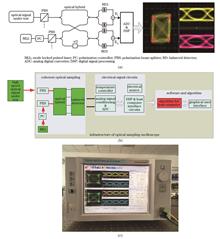
ObjectiveIn optical communication, the measurement and analysis of high-speed optical communication signals are essential in developing high-speed optical communication devices, equipment, and systems. At present, the common equipment for time-domain measurement of high-speed optical signals is an optoelectronic hybrid broadband oscilloscope, which has a signal processing circuit limit bandwidth of about 90 GHz and requires complex clock synchronization circuitry. Additionally, this type of oscilloscope also has disadvantages such as opaque signal rate and modulation format, complex system composition, and expensive price. To overcome this electronic bottleneck, we develop an optical sampling oscilloscope prototype based on optical domain sampling technology. The oscilloscope adopts a software synchronization algorithm, and the measurable signal bandwidth is up to THz without the requirement for high-speed photodetectors, which lowers the bandwidth requirements of the clock synchronization circuit and subsequent processing circuits. The limitation of the electronic bottleneck is also overcome. However, since we previously adopt a software synchronization algorithm based on chirped z-transform (CZT), its complexity affects the signal processing timeliness. To improve the signal processing efficiency and enhance the equipment practicability, it is necessary to study a less complex software synchronization algorithm suitable for optical sampling oscilloscopes.MethodsGenerally, after the optical signal is asynchronously down-frequency optically sampled with a fixed frequency difference, the eye diagram reconstruction algorithm based on software synchronization can be employed to realize parameter measurement of high-speed optical data signals related to the eye diagram recovery, constellation diagram, and signal statistical characteristics (Fig. 2). The key to the entire software synchronous eye diagram reconstruction algorithm is to accurately obtain the down-frequency equivalent sampling time step parameter Δt of asynchronous down-frequency optical sampling from the sampled digital signal. To reduce the complexity of software synchronization, based on the CZT software synchronization method proposed by our research group, we put forward a software synchronization method based on the zoom fast Fourier transform (ZoomFFT). The proposed software synchronization algorithm is divided into two steps of coarse synchronization based on FFT and fine synchronization based on ZoomFFT (Figs. 4-6). After the FFT coarse synchronization, ZoomFFT is adopted to refine the spectrum near the peak of the amplitude spectrum to obtain a more accurate peak frequency point of the amplitude spectrum. Then a more accurate down-frequency equivalent sampling time step parameter Δt is obtained to realize fine synchronization. Among them, after replacing the low-pass filter in the ZoomFFT transform with time-domain averaging, the computational complexity of ZoomFFT is lower than that of CZT.Results and DiscussionsFirst, we measure the four-level pulse amplitude modulation (PAM4) signal and quadrature phase-shift keying (QPSK) signal at different rates through an optical sampling oscilloscope prototype. In the measurement of the PAM4 signal, two rates of 6.259 GBaud and 9.696 GBaud are sent respectively. To compare with the downsampling signal, a high-speed broadband digital sampling oscilloscope with a sampling rate of 50 GSa/s and a bandwidth of 20 GHz is utilized to oversample the two-rate PAM4 signal. The results show that the software synchronous optical sampling oscilloscope can measure the eye diagram which is in good agreement with the oversampling broadband oscilloscope (Figs. 8-9). In the measurement of the QPSK signal, two rates of 10 GBaud and 20 GBaud are sent respectively. With the results measured by Agilent's real-time oscilloscope as a comparison, the software synchronous optical sampling oscilloscope can adaptively measure the eye diagram and constellation diagram of the QPSK signal with different symbol rates (Figs. 11-12). Meanwhile, we investigate the effect of the background noise in an optical sampling oscilloscope prototype, and the change curve of the Q value is measured by changing the input optical power. The results show that when the Q value decreases by 3 dB, the corresponding input optical power reduces by about 10.3 dB, and the influence of background noise is small (Fig. 14). It is worth noting that benefiting from the proposed ZoomFFT-based software synchronization algorithm, the complexity can be greatly reduced. Compared with the CZT algorithm, the complexity is reduced by 68.8%.ConclusionsBased on the previous research results of the software synchronization algorithm of the CZT transform, our paper proposes a software synchronization algorithm of the ZoomFFT transform. The experimental results show that the software synchronization algorithm based on ZoomFFT reduces the complexity by 68.8% compared with the CZT algorithm. With the developed optical sampling oscilloscope prototype, the optical PAM4 signals of 6.259 GBaud and 9.696 GBaud rates, and the optical QPSK signals of 10 GBaud and 20 GBaud are measured. The measurement results are compared with those of a broadband electrical sampling oscilloscope with a sampling rate of 50 GSa/s and a bandwidth of 20 GHz. The measurement results verify that the optical sampling oscilloscope can adaptively measure intensity-modulated signals and phase-modulated signals at different rates. Additionally, the effect of the background noise in the optical sampling oscilloscope is investigated. The results demonstrate that when the measured input optical signal power drops by 10.3 dB, the measured Q factor decreases by 3 dB. Thus, the influence of the background noise is small.
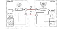
SignificanceAs cloud computing, the Internet of Things, and 5G technologies rapidly develop, global network traffic has experienced exponential growth. This surge in traffic, both within and between data centers, has fostered an ever-increasing demand for high-speed and high-performance optical fiber transmission systems for short- and medium-reach distances. Currently, the intensity-modulation and direct-detection (IMDD) system employing four-level pulse amplitude modulation (PAM4) is the primary solution for cost-sensitive short- and medium-reach transmission scenarios. The IMDD system features a simple structure, low power consumption, and low cost. However, it utilizes only the amplitude dimension of the optical carrier to transmit information, leaving other optical domain dimensions untapped. Additionally, the IMDD system's limited receiver sensitivity poses a challenge when higher-order modulation formats are tried to improve spectral efficiency. Coherent detection systems with higher receiver sensitivity are characterized by utilizing the polarization, phase, and amplitude of optical carriers to transmit information, which leads to higher spectral efficiency. However, their practical implementation in short- to medium-reach transmission scenarios brings about challenges including increased system complexity, higher power consumption of digital signal processing (DSP) chips employed in coherent detection systems, and the need for a high-performance narrow linewidth laser as a local oscillator (LO). These factors limit the widespread adoption of coherent detection in such scenarios.To this end, researchers have explored simplified coherent schemes, including self-homodyne coherent detection (SHCD) and differential self-coherent detection (DSCD) schemes for new-generation short- and medium-reach transmission systems. These schemes strike a balance between system performance and complexity, with higher receiver sensitivity than IMDD systems, and less complexity and costs than standard coherent detection. Among these schemes, the SHCD scheme has caught considerable attention. The SHCD system eliminates the need for a narrow linewidth laser as an LO on the receiver side by splitting the laser power at the transmitter between the transmitted signal and a remote LO. This allows utilizing an uncooled large linewidth laser in SHCD systems while the receiver sensitivity remains high. Extensive research efforts have been devoted to advancing the development of this scheme. The DSCD scheme, based on a differential modulation format, provides an alternative approach. It utilizes the relative phase information between two adjacent signals for self-coherent signal demodulation. A notable advantage of this scheme is its high tolerance to laser linewidth, which eliminates the need for LO and carrier phase recovery at the receiver side. Consequently, it enables the utilization of large linewidth lasers for coherent detection to reduce system cost and improve receiver sensitivity. In contrast to the SHCD scheme, the DSCD scheme overcomes the performance degradation caused by mismatched transmission paths of the signal and the remote LO. Recent research findings presented in our paper highlight that, in systems where receiver electrical noise is the primary impairment, the theoretical performance of DSCD is equivalent to that of SHCD. Additionally, DSCD outperforms SHCD in systems dominated by optical noise introduced by optical amplifiers. As a result, the DSCD technology provides a promising solution for high-speed and high-performance optical fiber transmission systems. Its advantages include high receiver sensitivity, low-cost implementation, and low power consumption, thus making itself an appealing choice in the field.ProgressIn terms of receiver sensitivity, implementation complexity, and performance in optical power-limited and optical signal-to-noise (OSNR) limited regimes, we review and compare the optical transmission schemes, including IMDD employing PAM4, SHCD employing quadrature phase shift keying (QPSK) modulation, and DSCD employing differential quadrature phase shift keying (DQPSK) modulation. In recent years, the IMDD system faces challenges in improving system transmission rates, while the SHCD system has gained attention as a low-cost, and high-performance solution. Sowailem's group from McGill University demonstrates a bidirectional SHCD scheme employing optical circulators for short-reach systems. Deming Liu's research group from Huazhong University of Science and Technology presents an SHCD system leveraging a large linewidth distributed feedback (DFB) laser as a downstream transmission solution for optical access networks. Ming Tang's research group from Huazhong University of Science and Technology proposes a real-time 400 Gbit/s bidirectional SHCD transmission by employing low-cost uncooled large linewidth DFB lasers for data center interconnects.However, the practical implementation of an SHCD system still encounters challenges. Bidirectional transmission of signals and remote LOs requires additional optical circulators in SHCD transceivers (Table 2). Furthermore, the sensitivity of the SHCD system to transmission path differences increases with the utilization of larger laser linewidth (Fig. 4). In contrast, the DSCD system exhibits high tolerance for laser linewidth and is unaffected by transmission path differences. In optical power-limited systems, the DSCD-DQPSK system yields comparable performance to the SHCD-QPSK system with optimal power separation ratio (Fig. 6), which is significantly better than the IMDD-PAM4 system (Fig. 7). In OSNR-limited systems, the remote LO quality is inevitably affected by optical noise, which influences the optimal laser power separation ratio (Fig. 8) and the receiver sensitivity of the SHCD system (Fig. 9). Implementing a narrow bandwidth optical filter for the remote LO can filter out a portion of the noise and enhance system performance but at the expense of additional costs. Conversely, in OSNR-limited systems, the receiver sensitivity of the DSCD-DQPSK system is superior to that of the SHCD-QPSK system, and it does not require an additional narrow bandwidth optical filter.Conclusions and ProspectsIn conclusion, both the SHCD and DSCD schemes realize a significant improvement in receiver sensitivity compared to the IMDD scheme. However, the increased DSP complexity and power consumption for coherent detection is a price for this improvement. Additionally, the SHCD system faces challenges from transmission path differences and noise within the remote LO, and addressing the challenges will increase the system implementation costs. Thus, further reducing DSP power consumption, system complexity, and cost is an important direction for future research for simplified self-coherent schemes. However, compared with the IMDD-PAM4 system and the SHCD-QPSK system, the proposed DSCD-DQPSK system is inherently advantageous and promising for short- and medium-reach optical fiber transmissions.
SignificanceHolographic three-dimensional (3D) display technology can effectively reconstruct the wavefront of 3D objects and provide whole depth cues for human eyes, so it has become a research hotspot in the 3D display field. Compared with optical holography, computer-generated holography simulates the recording process of the hologram by computers and adopts the refreshable spatial light modulator instead of holographic recording material as the hologram-carrying media. Due to the above characteristics, computer-generated holography becomes an ideal technology to realize real-time holographic 3D displays and has a broad application prospect in military navigation, industrial manufacturing, medical treatment, education, and entertainment fields. At present, the development of real-time holographic 3D displays is hindered by the huge data of 3D objects, the insufficient modulation capacity of spatial light modulators, and the low display degree of holographic 3D display systems. In order to overcome these problems, researchers have made many innovations from both algorithm and hardware aspects.ProgressWe review the progress of real-time holographic 3D displays. Firstly, the basic principle and development history of holography are outlined. Next, the fast calculation methods of computer generated holograms (CGHs) and wavefront coding methods for current spatial light modulators are introduced in detail. Then, the contribution of deep learning to real-time holographic 3D displays is discussed, and some typical holographic display systems are introduced. Finally, the future development of real-time holographic 3D displays is prospected. The fast calculation methods can be classified into algorithm optimization and hardware acceleration. The algorithm optimization mainly simplifies the calculation complexity and reduces the redundant computation of traditional calculation methods, including point-based method, polygon-based method, and layer-based method. Hardware acceleration mainly speeds up the CGH calculation by designing fast calculation algorithms adapted to the hardware platform and optimizing hardware system architectures. The wavefront coding methods for current spatial light modulators can be mainly classified into iterative methods and non-iterative methods. Iterative methods solve the desired phase-only hologram by iterative calculation between the image plane and the hologram plane or pixels in the hologram plane, which are time-consuming. Non-iterative methods convert the diffracted complex wavefront to an intensity-constant distribution analytically. Compared with iterative methods, non-iterative methods are more efficient and suitable for real-time holographic 3D displays. In recent years, deep learning is also introduced into the computer-generated holography field. Deep learning completes the CGH calculation and wavefront coding through the trained neural network, which shows great potential for realizing real-time holographic 3D displays. Furthermore, with the development of algorithms, devices, and systems, the holographic display system is gradually developing towards large size, large field of view, and real-time color display.Conclusions and ProspectsReal-time holographic 3D display is the ultimate goal of the holographic 3D display. Although there is still a long way to go, it is believed that there is great potential for the further development of real-time holographic 3D displays in both software (algorithms) and hardware (devices and systems). It is expected that holographic 3D displays will eventually achieve real-time display and come gradually into the market and daily life, thus bringing revolutionary changes to our future life.
SignificanceInfrared thermal imaging technology has a wide range of applications in military and civilian fields, and real-time digital image processing, as a key link of infrared imaging systems, has become an important part of thermal imaging technology research in China and abroad. With the development of infrared focal plane detectors (IRFPA) and intelligent image processing technologies, new thermal imaging modes and corresponding image processing methods have been continuously innovated, which have achieved some effective results.ProgressWe review the research and application of the research team in the new thermal imaging modes and their image processing technologies. 1) The non-uniformity correction (NUC) method combining scene-based time-domain high-pass and air-domain low-pass filtering, namely ITHP & GM is proposed, which can effectively correct the "water streak" non-uniformity noise that the existing algorithm fails to effectively deal with, and the algorithm transplantation has been realized on the FPGA hardware platform and applied in a mid-wave infrared cooling thermal imaging camera. 2) The focal plane infrared polarizer arrays with 4-polarization and 3-polarization +1 intensity division are designed and developed, and the coupling and imaging with the refrigerated MW-IRFP movement (320 pixel×256 pixel, 25 μm) and the uncooled LW-IRFPA movement (640 pixel×512 pixel, 17 μm) are realized. A correction model of the front polarizer-based polarization thermal imaging system is proposed, which can effectively reduce the radiation and reflection effects of the polarizer in the optical path. 3) The overclocked high dynamic range (HDR) thermal imaging experimental system based on 256×256 long-wave IRFPA is developed and combined with the HDR image fusion method of multi-integration time image fusion-detail enhancement cascade, and real-time HDR thermal imaging (with delay less than 40 ms) is realized, which can normally observe and identify targets under the background of strong radiation such as the sun, jamming bombs, and flames. 4) The bionic compound eye thermal imaging mode with the partially overlapped field of view of four apertures and four/five apertures is proposed, and the experimental system of four-aperture bionic compound eye thermography based on 640×480 and 80×80 uncooled IRFPA is built, which realizes variable spatial resolution imaging with a large field of view searching and high-resolution imaging of central field of view and verifies the characteristics and effectiveness of bionic compound eye thermography. 5) The TIV-Net algorithm for the conversion of thermal infrared to visible color images is proposed. 75000 pairs of image datasets are completed, and the real-time processing that is not less than 20 Hz is realized on platforms such as vehicle platforms and drones. The real-time conversion of day and night thermal images to natural color visible light images through deep learning methods is proven, which effectively improves the situational awareness ability of day and night human eye vision through thermal imagers.Conclusions and ProspectsThe research progress of the research team in new thermal imaging modes and image processing technologies is reviewed, including the NUC method combining scene-based time-domain high-pass and airspace low-pass filtering, correction model of division of focal plane infrared polarizer arrays based on infrared polarization imaging, front polarizer-based polarization thermography system, overclocking HDR thermal imaging experimental system of long-wave IRFPA, bionic compound eye thermal imaging mode and its experimental system with the partially overlapped field of view of four apertures and four/five apertures, TIV-Net algorithm converting thermal infrared to visible color images, etc. Such technology research has made innovative technological breakthroughs or has been applied, showing a wide range of application prospects, which can be an important direction for further research and expansion.
SignificanceIn recent years, advancements in computing software and hardware have led to artificial intelligent (AI) models achieving performance levels approaching or surpassing human capabilities in perceptive tasks. However, in order to develop mature AI systems that can comprehensively understand the world, models must be capable of generating visual concepts, rather than simply recognizing them because creation and customization require a thorough understanding of high-level semantics and full details of each generated object.From an applied perspective, when AI models obtain the capability of visual understanding and generation, they will significantly promote progress and development across diverse aspects of the industry. For example, visual generative models can be applied to the following aspects: colorizing and restoring old black and white photos and films; enhancing and remastering old videos in high definition; synthesizing real-time virtual anchors, talking faces, and AI avatars; incorporating special effects into personalized video shooting on short video platforms; stylizing users' portraits and input images; compositing movie special effects and scene rendering, and so on. Therefore, research on the theories and methods of image and video generation models holds significant theoretical significance and industrial application value.ProgressIn this paper, we first provide a comprehensive overview of existing generative frameworks, including generative adversarial networks (GAN), variational autoencoders (VAE), flow models, and diffusion models, which can be summarized in Fig. 5. GAN is trained in an adversarial manner to obtain an ideal generator, with the mutual competition of a generator and a discriminator. VAE is composed of an encoder and a decoder, and it is trained via variational inference to make the decoded distribution approximate the real distribution. The flow model uses a family of invertible mappings and simple priors to construct an invertible transformation between real data distribution and the prior distribution. Different from GANs and VAEs, flow models are trained by the estimation of maximum likelihood. Recently, diffusion models emerge as a class of powerful visual generative models with state-of-the-art synthesis results on visual data. The diffusion model decomposes the image generation process into a sequence of denoising processes from a Gaussian prior. Its training procedure is more stable by avoiding the use of an adversarial training strategy and can be successfully deployed in a large-scale pre-trained generation system.We then review recent state-of-the-art advances in image and video generation and discuss their merits and limitations. Fig. 6 shows the overview of image and video generation models and their classifications. Works on pre-trained text-to-image generation models study how to pre-train a text-to-image foundation model on large-scale datasets. Among those T2I foundation models, stable diffusion becomes a widely-used backbone for the tasks of image/video customization and editing, due to its impressive performance and scalability. Prompt-based image editing methods aim to use the pre-trained text-to-image foundation model, e.g., stable diffusion, to edit a generated/natural image according to input text prompts. Due to the difficulty of collecting large-scale and high-quality video datasets and the expensive computational cost, the research on video generation still lags behind image generation. To learn from the success of text-to-image diffusion models, some works, e.g., video diffusion model, imagen video, VIDM, and PVDM, have tried to use enormous video data to train a video diffusion model from scratch and obtain a video generation foundation model similar to stable diffusion. Another line of work aims to resort to pre-trained image generators, e.g., stable diffusion, to provide content prior to video generation and only learn the temporal dynamics from video, which significantly improves the training efficiency.Finally, we discuss the drawbacks of existing image and video generative modeling methods, such as misalignment between input prompts and generated images/videos, further propose feasible strategies to improve those visual generative models, and outline potential and promising future research directions. These contributions are crucial for advancing the field of visual generative modeling and realizing the full potential of AI systems in generating visual concepts.Conclusions and ProspectsUnder the rapid evolution of diffusion models, artificial intelligence has undergone a significant transformation from perception to creation. AI can now generate perceptually realistic and harmonious data, even allowing visual customization and editing based on input conditions. In light of this progress in generative models, here we provide prospects for the potential future forms of AI: with both perception and cognitive abilities, AI models can establish their own open world, enabling people to realize the concept of "what they think is what they get" without being constrained by real-life conditions. For example, in this open environment, the training of AI models is no longer restricted by data collection, leading to a reformation of many existing paradigms in machine learning. Techniques like transfer learning (domain adaptation) and active learning may diminish in importance. AI might be able to achieve self-interaction, self-learning, and self-improvement within the open world it creates, ultimately attaining higher levels of intelligence and profoundly transforming humans' lifestyles.
SignificanceSingle object tracking (SOT) is one of the fundamental problems in computer vision, which has received extensive attention from scholars and industry professionals worldwide due to its important applications in intelligent video surveillance, human-computer interaction, autonomous driving, military target analysis, and other fields. For a given video sequence, a SOT method needs to predict the real-time and accurate location and size of the target in subsequent frames based on the initial state of the target (usually represented by the target bounding box) in the first frame. Unlike object detection, the tracking target in the tracking task is not specified by any specific category, and the tracking scene is always complex and diverse, involving many challenges such as changes in target scales, target occlusion, motion blur, and target disappearance. Therefore, tracking targets in real-time, accurately, and robustly is an extremely challenging task.The mainstream object tracking methods can be divided into three categories: discriminative correlation filters-based tracking methods, Siamese network-based tracking methods, and Transformer-based tracking methods. Among them, the accuracy and robustness of discirminative correlation filter (DCF) are far below the actual requirements. Meanwhile, with the advancement of deep learning hardware, the advantage of DCF methods being able to run in real time on mobile devices no longer exists. On the contrary, deep learning techniques have rapidly developed in recent years with the continuous improvement of computer performance and dataset capacity. Among them, deep learning theory, deep backbone networks, attention mechanisms, and self-supervised learning techniques have played a powerful role in the development of object tracking methods. Deep learning-based SOT methods can make full use of large-scale datasets for end-to-end offline training to achieve real-time, accurate, and robust tracking. Therefore, we provide an overview of deep learning-based object tracking methods.Some review works on tracking methods already exist, but the presentation of Transformer-based tracking methods is absent. Therefore, based on the existing work, we introduce the latest achievements in the field. Meanwhile, in contrast to the existing work, we innovatively divide tracking methods into two categories according to the type of architecture, i.e., Siamese network-based two-stream tracking method and Transformer-based one-stream tracking method. We also provide a comprehensive and detailed analysis of these two basic architectures, focusing on their principles, components, limitations, and development directions. In addition, the dataset is the cornerstone of the method training and evaluation. We summarize the current mainstream deep learning-based SOT datasets, elaborate on the evaluation methods and evaluation metrics of tracking methods on the datasets, and summarize the performance of various methods on the datasets. Finally, we analyze the future development trend of video target tracking methods from a macro perspective, so as to provide a reference for researchers.ProgressDeep learning-based target tracking methods can be divided into two categories according to the architecture type, namely the Siamese network-based two-stream tracking method and the Transformer-based one-stream tracking method. The essential difference between the two architectures is that the two-stream method uses a Siamese network-shaped backbone network for feature extraction and a separate feature fusion module for feature fusion, while the one-stream method uses a single-stream backbone network for both feature extraction and fusion.The Siamese network-based two-stream tracking method constructs the tracking task as a similarity matching problem between the target template and the search region, consisting of three basic modules: feature extraction, feature fusion, and tracking head. The method process is as follows: The weight-shared two-stream backbone network extracts the features of the target template and the search region respectively. The two features are fused for information interaction and input to the tracking head to output the target position. In the subsequent improvements of the method, the feature extraction module is from shallow to deep; the feature fusion module is from coarse to fine, and the tracking head module is from complex to simple. In addition, the performance of the method in complex backgrounds is gradually improved.The Transformer-based one-stream tracking method first splits and flattens the target template and search frame into sequences of patches. These patches of features are embedded with learnable position embedding and fed into a Transformer backbone network, which allows feature extraction and feature fusion at the same time. The feature fusion operation continues throughout the backbone network, resulting in a network that outputs the target-specified search features. Compared with two-stream networks, one-stream networks are simple in structure and do not require prior knowledge about the task. This task-independent network facilitates the construction of general-purpose neural network architectures for multiple tasks. Meanwhile, the pre-training technique further improves the performance of the one-stream method. Experimental results demonstrate that the pre-trained model based on masked image modeling optimizes the method.Conclusions and ProspectsOne-stream tracking method with a simple structure and powerful learning and modeling capability is the trend of future target tracking method research. Meanwhile, collaborative multi-task tracking, multi-modal tracking, scenario-specific target tracking, unsupervised target tracking methods, etc. have strong applications and demands.
SignificanceThis study reports several typical advances in three categories of computational imaging techniques based on multidimensional optical field manipulation: speckle imaging, spatial and temporal compressive imaging, and compressive computational spectral imaging. Additionally, existing problems and future research prospects are analyzed and discussed herein.High-quality imaging through scattering media has crucial applications in biomedicine, astronomy, remote sensing, traffic safety, etc. Object photons traveling through a scattering medium can be classified as ballistic, snake, or diffusive photons based on the degree of deviation from their initial propagation directions. Ballistic photons can maintain their initial directions and retain undistorted object information. Using gated ballistic photons, optical coherence tomography, multiphoton microscopy, and confocal microscopy have been employed to successfully image objects hidden behind scattering media. However, in the presence of a strong scattering medium, all incident photons become diffusive after multiple scatterings and form a speckle pattern. Hence, the abovementioned techniques based on gated ballistic photons fail to image hidden objects. Therefore, the speckle imaging technology was developed to overcome this limitation. This technology involves three main steps: first, establishing a physical model of speckle formation; second, measuring and statistically analyzing the speckle light field; and finally, computationally reconstructing the hidden objects.An imaging system with high spatial and temporal resolution can obtain rich spatial and motion details of high-speed moving scenes. Improvement in spatial and temporal resolutions depends on hardware-performance improvement, including attaining high resolution and low noise in a detector array and satisfactory optical design. However, owing to the limitations in the development of semiconductors and manufacturing technologies, manufacturing a high-performance detector is difficult and costly. Additionally, the huge volume of data collected using an imaging system mandates strict requirements for read-out circuits and back-end data processing platforms. Moreover, miniaturization of the system becomes a general concern that conflicts with these high-performance requirements. Hence, further improvement in the performance of imaging systems cannot be realized based solely on hardware improvement. Compressive imaging is an imaging technology based on the compressed sensing principle and development in computer science, which realizes signal coding and compression simultaneously. Combined with back-end reconstruction algorithms, compressive imaging greatly improves the performance of an imaging system and is widely used in various imaging applications.Spectral imaging technology combines imaging and spectral technologies; thus, this technology can obtain the spatial and spectral information of an object simultaneously. Compared with traditional imaging technologies, the spectral imaging technology possesses a remarkable advantage of sensing information from a multidimensional optical field. By analyzing spectral images, highly detailed target information can be obtained, which is helpful for target recognition as well as substance detection and classification. With the development of compressed sensing theory, a new type of computational imaging technology termed as coded aperture snapshot spectral imaging (CASSI) was proposed. Subsequently, CASSI has become an advanced research topic in the field of imaging. CASSI integrates optical modulation, multiplexing detection, and numerical reconstruction algorithm to address the issues of imaging complex systems, low efficiency of data acquisition, and limited resolution in traditional snapshot spectral imaging technologies. In future, CASSI can play an important role in agriculture, military, biomedicine, and other fields, realizing fast and accurate spectral imaging approaches using intelligent perception capability.ProgressThe speckle correlation imaging method proposed by Bertolotti et al. introduced the concept of speckle imaging. They analyzed the autocorrelation of speckle images captured under different laser illumination angles and subsequently achieved noninvasive reconstruction of objects with phase retrieval. Katz et al. simplified the speckle imaging system using incoherent light illumination and then achieved reconstruction using a single speckle image. Since then, substantial progress has been observed in speckle imaging technology, pertaining to improving accuracy and scene applicability, expanding the imaging field of view and depth of field, and enhancing the ability of the technology to decode objects' optical field parameters, thus becoming a highly researched topic in computational imaging. This study introduces our primary research results regarding key technologies related to speckle imaging, including recursion-driven bispectral imaging with respect to dynamic scattering scenes, learning to image and track moving objects through scattering media via speckle difference, and imaging through scattering media under ambient-light interference.Developing high resolution detectors in the infrared band is considerably difficult compared with developing detectors in the visible band. Therefore, herein, we focused on studying compressive imaging in infrared band. The optical hardware systems and reconstruction algorithms related to spatial and temporal infrared compressive imaging are introduced and our related research is introduced in this study. We set up a mediumwave infraredblock compressive imaging system (Fig.9) and discussed obtained results herein, including reducing block effect, removing stray light, limiting nonuniform (Fig.10), improving real-time performance (Fig.11). For the back-end processing of measured data, we reviewed the traditional methods and proposed several reconstruction algorithms based on deep learning in this study. With respect to spatial compressive imaging, we designed Meta-TR, which combined meta-attention and transformer (Fig.12); furthermore, we designed a multiframe reconstruction network named Joinput-CiNet (Fig.13). Moreover, we introduced a novel version of a 3D-TCI network to achieve temporal reconstruction (Fig.14). Moreover, the spatial–temporal compressive imaging method, which combines temporal and spatial compression, is briefly discussed herein (Fig.16).Furthermore, we reviewed relevant studies in the field of compressive computational spectral imaging that covered the development of color-coded aperture and use of the latest transformer network to improve the image-reconstruction quality. Additionally, we summarized our research achievements. First, we proposed an optical-axis-shift CASSI system based on a digital micromirror device, which can effectively suppress off-axis aberration (Fig.17). Second, we proposed a 3D coded convolutional neural network capable of realizing hyperspectral image classification (Fig.19) based on the established dual-disperser CASSI system (Fig.18). Subsequently, we proposed a hexagonal, blue-noise, complementary-coded aperture (Fig.20) and spatial-target adaptive-coded aperture (Fig.21) for improving the perceptual efficiency of CASSI systems. Finally, to enhance the quality of reconstructed spectral images, we proposed a fast alternating minimization algorithm based on the sparsity and deep image priors (Fama-SDIP) (Fig.22).Conclusions and ProspectsWe achieved remarkable results in three categories of computational imaging techniques based on multidimensional optical field manipulation: speckle imaging, spatial and temporal compressive imaging, and compressive computational spectral imaging. However, these techniques still face numerous challenges in terms of practical applications, including realizing a compact system design, mounting and error calibration, coded aperture preparation, fast and accurate reconstruction of optical fields, and lightweight design of networks. In future, researchers can combine the field of micro-/nano-optics with computational imaging mechanisms to further improve the manipulation ability of imaging systems. Moreover, artificial intelligence can be used to improve the scope of practical application of imaging systems.
ObjectiveWith the widespread application of infrared imaging guidance technology in various offensive and defensive precision guided weapons, infrared imaging guidance hardware-in-the-loop simulation technology has undergone rapid development. Missile flight tests in the laboratory can significantly reduce the outfield testing cost. This reflects the importance of developing hardware-in-the-loop simulation test systems for infrared imaging guidance. Infrared imaging scene projection technology is one of the key technologies in infrared imaging guidance of hardware-in-the-loop simulation technologies. Infrared scene projection systems are mainly employed to replicate various types of optical targets, backgrounds, and optical environment interference in different infrared bands. Nowadays, optical detection systems are complex, multi-spectral, and high-resolution with high frame rate, high dynamic range, and even scene-sensitive systems containing distance information. The main sensors include missile seeker, forward looking infrared system (FLIR), target tracking device, and automatic target recognition device. Although infrared scene projection technology has made significant progress in recent years, the current infrared scene projection technology still cannot meet the performance requirements of testing these complex optical detection systems. It is necessary to study complex infrared scene projection systems for different optical detection applications.MethodsMulti-spectral complex infrared scene projection technology is the key technology to infrared imaging guidance of hardware-in-the-loop simulation system technology, and its technical characteristics limit the overall performance of the entire simulation system. The technical approaches to multi-spectral complex infrared scene projection mainly include resistor array, photothermal image conversion array, digital micro-mirror device (DMD), liquid crystal spatial light modulator, infrared LED array, phase change material array, tunable emissivity semiconductor screen, quantum dot down-conversion chip, photoluminescent phosphor material, and photonic crystal. We review the development history of multi-spectral complex infrared scene projection technology, introduce the implementation principles of typical technologies, discuss the relative advantages and disadvantages of each technology, and summarize the research of major research institutions at home and abroad. Finally, the performance parameters of these technologies are compared.Results and DiscussionAccording to the mechanism of infrared scene projection, the current infrared scene projection systems are divided into two categories of radiation type and modulation type. Radiation type includes resistor array and photothermal image conversion array. Modulation type includes DMD and liquid crystal spatial light modulator. Other infrared scene projection technologies are also introduced, such as infrared LED array, phase change material array, tunable emissivity semiconductor screen, quantum dot down-conversion chip, photoluminescent phosphor material, and photonic crystal. Resistor array and photothermal image conversion array can provide both mid-infrared and long-infrared scenes. DMD and infrared LED arrays can only generate mid-infrared scenes, but they achieve a frame rate beyond 200 Hz.ConclusionsSome of the infrared scene projection devices discussed in this paper have been employed in hardware-in-the-loop simulation test systems, and some are under development. Resistor arrays of the SBIR company, DMD of TI company, and the infrared LED array from the University of Delaware have been applied in hardware-in-the-loop simulation test systems. The technologies developed domestically based on resistor arrays, photothermal image conversion arrays, DMD, and other devices have also been adopted in hardware-in-the-loop simulation test systems for testing infrared systems. The various technologies discussed in this paper have shown their characteristics, which can provide most of the functions in current optical guidance hardware-in-the-loop simulation experiments. This study can serve as a reference during selecting solutions for specific applications to detect infrared systems.
SignificanceHyperspectral images are made up of tens or even hundreds of contiguous spectral bands for each spatial position of the target scene. Consequently, each pixel in a hyperspectral image contains the complete spectral profile of that specific position. With the superiority of high spectral resolution and image-spectrum merging, hyperspectral imaging has emerged as a powerful tool to obtain multi-dimensional and multi-scale information and has important applications in precision agriculture, mineral identification, water quality monitoring, gas detection, food safety, medical diagnosis, and other fields.Due to the limitations of existing devices, materials, and craftsmanship, traditional hyperspectral imaging technology still suffers from the contradiction between high spatial resolution and high spectral resolution, as well as large data volume and high redundancy in practical applications. The emergence of computational imaging technology has brought new ideas to traditional hyperspectral imaging, and thus a new research field, namely hyperspectral computational imaging has been bred. Hyperspectral computational imaging uses system-level imaging methods to establish the relationship between target scenes and observation results in a more flexible sampling form and jointly optimizes the front-end optical system and back-end processing system, thus fundamentally breaking through the limitations of traditional hyperspectral imaging technology to achieve high-dimensional and high-resolution acquisition of hyperspectral information.Currently, there are numerous hyperspectral computational imaging systems based on various theories and methods, and hyperspectral computational imaging systems based on compressive sensing theory are key branches. The compressive sensing (CS) theory can acquire the signal at much lower than the Shannon-Nyquist sampling rate, solve the underdetermined problem based on the sparse a priori of the signal, and finally recover the original high-dimensional signal with high accuracy. Compressive hyperspectral computational imaging obtains spectral images of the target scene by computing the compressive projections acquired on the detector through reconstruction algorithms, thus significantly improving the system performance while keeping the characteristics of the system components unchanged.For compressive hyperspectral computational imaging, how to design the computational model is a crucial scientific challenge. The coded aperture snapshot spectral imager (CASSI) is a classical model, in which the scene information is projected onto the detector through coded apertures and dispersive elements, and the original data cube is subsequently recovered by the reconstruction algorithm. However, the CASSI system can only obtain a limited number of spectral bands due to the performance of dispersive elements and the detector, which makes it difficult to achieve high spectral resolution detection. Moreover, the reconstruction quality still has much room for improvement because the reconstruction solution problem is too underdetermined. To address the above problems, our team proposes the compressive hyperspectral computational imaging technique via spatio-spectral coding, which achieves super-resolution in both spatial and spectral dimensions and effectively solves the contradiction between high spatial resolution and high spectral resolution. Furthermore, our team has carried out a series of work on improving the quality of system reconstruction and expanding the dimensionality of acquired information, so as to achieve high quality acquisition of high-dimensional and high-resolution hyperspectral data cubes. The research on compressive hyperspectral computational imaging via spatio-spectral coding has laid a solid foundation for the hyperspectral computational imaging technology towards practical applications. Hence, it is important and necessary to summarize the background knowledge of compressive hyperspectral computational imaging and the research work of compressive hyperspectral computational imaging via spatio-spectral coding, which can bring new ideas for researchers to explore the new architecture of compressive hyperspectral computational imaging and promote the development of hyperspectral computational imaging technology.ProgressFirst, the research background and basic concepts of hyperspectral computational imaging are outlined. Then, the current development status of compressive hyperspectral computational imaging systems is summarized, and two classical forms and subsequently improved designs are detailed: one is the coded aperture snapshot spectral imager and the improved systems derived from it, and the other is the hyperspectral computational imaging system based on liquid crystal and the improved systems derived from it. Subsequently, the compressive hyperspectral computational imaging technique via spatio-spectral coding proposed by our team is highlighted, and the system composition, mathematical and theoretical models, and the latest progress are presented. Our team has worked on the coded aperture design and reconstruction algorithm optimization (Fig. 13) to improve the reconstruction quality of the system. The study on the acquisition of polarization dimension information (Fig. 14) is carried out to expand the information acquisition dimension of the proposed system. Finally, the future research trends of compressive hyperspectral computational imaging via spatio-spectral coding are discussed.Conclusions and ProspectsCompressive hyperspectral computational imaging technology has a wide range of application prospects. We review compressive hyperspectral computational imaging, including its basic principles, representative systems, and key technologies, so as to provide background knowledge for scholars to engage in related research. Compressive spectral computational imaging via spatio-spectral coding can overcome the contradiction between high spatial resolution and high spectral resolution, and it has made progress in improving the reconstruction quality and expanding the information dimension, which is expected to solve more scientific and engineering challenges. In the future, in-depth research will continue in optimizing the optical design of the system, applying deep learning algorithms for reconstruction, using adaptive compressive sensing theory to improve the imaging quality, and increasing the dimensions of time and depth, so as to promote the practical and industrial development of hyperspectral computational imaging systems.
ObjectiveIn view of the differences in polarization characteristics caused by different states of the detected targets, different radiation spectra, different sizes and shapes, complex transmission environment of soot and haze, and variable light field interference, we conduct the target multispectral polarization model and polarization characteristic transmission model, develop the optimal design method of micro-nano grating polarizer array, put forward the principle and schemes of high-resolution imaging detection instruments, and propose a novel deep network to solve the polarization image fusion problem through a self-learning strategy. We aim to use multispectral polarization imaging technology to solve the problems of complex optical field interference, limited visible distance, and insufficient classification ability of optical imaging under harsh conditions.MethodsIn this paper, the polarization imaging detection method and multispectral information fusion technology are studied, and the overall scheme of the multispectral polarization imager is proposed. Scientific methods such as the theory and model of target polarization characteristics under complex optical fields, micro-nano grid focal plane polarization device, optimization and testing of a multispectral fully polarized imaging system, and polarization image processing based on polarization difference characteristics are condensed.Key technologies and solutions such as modeling and testing of target polarization characteristics generation and transmission, optimization of metal micro-nano grating polarization elements with high extinction ratio, the optical design of multispectral polarization imaging and testing system, and multispectral polarization information processing are analyzed. This will lay the foundation for the development of a multispectral polarization imaging detection test prototype, which will meet the practical application requirements of visual assistance and guidance in optical imaging.Results and DiscussionsWe conduct the target multispectral polarization model and polarization characteristic transmission model, which reveal typical target multispectral polarization law and haze and dusty weather multispectral polarization transmission law and provide theoretical basis for multispectral polarization information processing.We develop the optimal design method of micro-nano grating polarizer array, solve the defects of the current defocused plane polarization imaging device that only has micro-nano linear grating and cannot produce circular polarization, and propose a new chiral micro-nano circular grating mechanism. We also analyze the physical nature of the low extinction ratio of the division of focal plane polarization imaging, put forward the physical mechanisms for the generation of the high extinction ratio of the linear grating, and discuss the effect of the deviation of the preparation parameter on the extinction ratio law. Combining the micro-nano linear grating and circular grating, we study the new device of full polarization high extinction ratio and split focal plane imaging, and lay the technical foundation for the development of multispectral and multi-dimensional polarization high-resolution imaging detection instruments.Aiming at the problems of close detection distance, low detection sensitivity, and narrow environmental application range of the existing instruments under the haze and smoke conditions, we put forward the principle and scheme of multispectral polarization high-resolution imaging detection instruments and the design scheme of multi-optical imaging optical system for the characteristics of large loss of light energy in polarization imaging. We break through the optical system design based on the polarization aberration correction and multispectral polarization calibration, so as to significantly improve the instrument's imaging and detection ability in the haze and dusty environment.A novel deep network is proposed to solve the polarization image fusion problem through a self-learning strategy. The network consists of an encoder layer, a fusion layer, and a decoder layer, where the feature maps extracted by the encoder are fused and then fed into the decoder to generate a fused image. Given a multidimensional polarization image, effective features are extracted from this source image, which are fused to form an information-rich polarization image for subsequent advanced image applications.ConclusionsAiming at the problems of "not recognizing", "not seeing far", and "not being able to recognize" in optical detection caused by harsh environments and meteorological conditions, we put forward a multispectral polarization imaging detection technology and expect to achieve breakthroughs in three aspects: 1) in terms of device development, through the improvement of circular micro-nano grid design method and micro-nano grid substrate material-structure, it is necessary to prepare new devices with high extinction score of focal plane imaging; 2) in terms of system design, breakthroughs are required in the design of multi-optical path bias-preserving optical system, high-transmittance and high bias-preserving optical coating and other key technologies, and high spatial and temporal matching of instrument information acquisition; 3) in terms of information processing, the study of the polarization characteristic model and polarization transmission model of the target is important.Adverse environmental and weather conditions not only have a great influence on optical imaging detection but also have an extremely serious effect on aircraft landing safety and other areas. Fog and low visibility conditions cause aircraft to fail to land properly, making flights grounded or delayed, with significant economic and social impacts. At present, to perform approach and landing under low visibility conditions, pilots mostly use ground and airborne navigation facilities/equipment to guide the aircraft to the runway in accordance with the specified flight path, mainly including instrument landing system ILS, microwave landing system MLS, satellite navigation technology GPS, laser landing system, and visual landing system. Under extremely severe conditions such as no radar guidance or no ground indication, the aircraft cannot obtain effective and safe landing guidance and assistance through the above guidance methods. Therefore, it is of great significance to develop visual aids for aircraft landing under adverse conditions. It can improve the safety of airplane landing under bad conditions such as smoke environments, sea fog environments, and low illumination environments.
SignificanceAs a significant optical precision measuring technology, optical interferometry is known for its wavelength-level measurement accuracy. As the industry calls for higher demands on measurement accuracy, the requirements on the sensing range of measurement methods are also increasingly wide. Additionally, due to the influence of human traffic, construction, and other factors, some measurement methods insensitive to environmental changes should be urgently proposed. These demands on the industry drive the development of optical interferometry. A lot of interference testing techniques have emerged in the development of optical interferometry. One of these techniques is lateral shearing interferometry which is common optical path interferometry and features a wide detection range and low need for environmental stability or coherence of the light source. As a result, this kind of interferometry has a variety of applications.The lateral shearing interferometry originated from the Ronchi test in 1923 with a history of one hundred years, it can be divided into double-beam lateral shearing interferometry and multi-beam lateral shearing interferometry. The double-beam lateral shearing interferometry needs at least two interferograms with different shear directions to recover the full wavefront phase information. This is because the interferogram of double-beam lateral shearing interferometry only contains the wavefront phase information about the shear direction, while this problem is resolved by multi-beam lateral shearing interferometry. Through this technology, the wavefront can be copied into multiple wavefronts to different emission angles at the same time, and then a multi-beam lateral shear interferogram is formed over the overlapping region of the observation surface. Therefore, each interferogram contains information about the phase differences between the wavefronts in multiple shear directions. Thus, only one interferogram is necessary to recover the wavefront to be measured through technical steps such as phase extraction, phase unwrapping, and wavefront reconstruction, which greatly improves the measurement efficiency and makes real-time detection of instantaneous wavefronts possible.In multi-beam lateral shearing interferometry, it is necessary to copy incident light waves of multiple light waves simultaneously, which requires obtaining the mutually interfering working wavefront and removing unwanted advanced diffracted light, and the key is in the design of light-splitting elements. The initial development of multi-beam lateral shearing interferometry employs prisms with high work surface processing requirements as the light-splitting elements, and then gratings are adopted to reduce the difficulty in device processing and improve the accuracy of the interference wavefront vector direction. Compared with other traditional interference methods, this technique greatly simplifies the whole measurement system. Quadri-wave lateral shearing interferometry (QWLSI) is characterized by high accuracy, large dynamic range, high resolution, and strong anti-interference ability. For example, due to the system simplicity, the QWLSI based on randomly coded hybrid grating theoretically requires only a two-dimensional grating and CCD. Thus it is the research focus of many research institutions in China and abroad. In recent years, QWLSI has been applied to the aberration detection of lithography objective lens, the surface shape detection of aspheric elements, and the wavefront sensing of large aperture splicing telescope. However, in pursuit of higher measurement accuracy today, a series of improvements still need to be conducted. Therefore, summarizing the completed work is a necessity, which is beneficial to better guide future work.ProgressThe development of our research team in several QWLSI areas is outlined. First, we describe the beam splitter design in QWLSI. Based on the randomly coded grating designed by Zhejiang University, our research group designs a global random coded hybrid grating that can better suppress the high-order secondary diffracted light and a phase-only grating based on global random coding constraint with low processing difficulty and high light transmittance. Second, we present our efforts to process interferograms. In the interferogram preprocessing field, we study the extension technique appropriate for two-dimensional QWLSI interferogram to reduce the measurement error caused by the boundary effect. The virtual grating phase-shifted Moiré fringe approach has been researched in terms of phase extraction. The present Fourier transform method's issues with substantial edge errors and weak anti-noise ability are resolved, and the algorithm's phase extraction accuracy and spectrum leaking are thoroughly investigated. In phase unwrapping, our team has studied the parallel phase unwrapping technique, which can speed up interferogram processing and significantly improve efficacy. Additionally, we research the algorithm of employing the wavefront differential phase of QWLSI in multiple directions to reconstruct the wavefront for improving the accuracy and anti-noise ability of wavefront reconstruction. Third, we investigate the QWLSI errors, including the processing error and installation and adjusting errors of the grating. Technical support for QWLSI installation and adjustment is provided by the quantitative results of the machining error tolerance of the grating and the influence of installation and adjustment error on measurement accuracy. The built fundamental QWLSI device based on the research on important technologies is then introduced, and the measurement accuracy in absolute terms is provided.Conclusions and ProspectsThe QWLSI with gratings as beam splitters have been the recent research subject in pertinent academic institutions domestically and internationally. Our research team has created the fundamental QWLSI device based on important studies. As expanding the application of QWLSI in related sectors, we will conduct research on the essential technologies to enhance the amplitude and spatial frequency of the detectable wavefront distortion in QWLSI.
SignificanceImaging photoplethysmography (IPPG) has the advantages of high cost performance, simple equipment operation, and continuous automatic measurement and observation of subjects. IPPG has become an important means to deeply understand the optical properties of biological tissue and explore the pathological mechanisms related to complex cardiovascular diseases. IPPG is developed on the basis of traditional single-point photoplethysmography (PPG). IPPG uses imaging equipment to record the tiny changes in skin colors caused by the diffuse reflected light carrying the pulsation information of the heart after the interaction between light and skin tissue in the form of continuous images. Then, through video and image processing technologies, human vital sign information such as pulse, heart rate, and heart rate variability are extracted from the video stream. IPPG can reveal the dynamic and small changes in biological tissue during physiological and pathological processes. Therefore, IPPG can be used to better understand basic life activities and realize highly sensitive diagnoses and high-precision quantitative characterization of diseases. IPPG is applicable to large-scale clinical detection and physical health monitoring in daily life and other scenarios. It is a research hotspot of human daily physiological status monitoring in the new era of medical health.ProgressIn recent years, due to the continuous improvement of imaging sensor resolution and various signal processing technologies, IPPG has made great progress in the detection and application of human physiological parameters, such as heart rate, respiratory rate, and heart rate variability, as well as the application of disease diagnosis, such as arterial disease, stiffness and aging, and chronic microcirculation disease. However, for the further monitoring and classification diagnosis of complex cardiovascular diseases, IPPG still faces the challenges of lack of pathological feature analysis, complex optical feature parameters, and the manifestation of different types of pathological mechanisms of cardiovascular diseases on pulse waves. Therefore, we summarize the basic research and application of the existing IPPG and continue to explore the optical mechanism and pathological mechanism of IPPG. These efforts are very important for guiding the future development of IPPG.Based on a comprehensive investigation of a large number of relevant literatures on the monitoring of human physiological parameters by IPPG in China and abroad in the past 20 years and our long-term research work, we first introduce the optical principle of IPPG. Then, we analyze the new method of IPPG signals in video image processing and that of improving the signal-to-noise ratio (Table 1), including a series of mainstream methods for selecting imaging sites in different areas of skin tissue and those for motion artifacts and blur. Finally, the clinical application of IPPG is introduced in detail, mainly including the extraction of IPPG heart rate under adaptive focal length, detection of living skin, measurement of blood oxygen saturation under visible light (Fig. 7), monitoring of fatigue status, evaluation of psychological stress, and analysis of the pathological mechanism of IPPG signals under cardiovascular diseases (Fig. 9).Conclusions and ProspectsIPPG is gradually developing towards miniaturization and intelligence. The monitoring indicators and accuracy of IPPG are continuously improving, which has important research significance and application value in biomedical research, clinical medicine, and daily life health monitoring. As an effective tool for early diagnosis of diseases and individual precision medical treatment, IPPG still needs in-depth and detailed exploration to promote its further development in academic and engineering fields.
SignificanceCompared with conventional optical fiber lasers, linearly polarized fiber lasers are widely used in coherent detection, coherent combination, polarization combination, and nonlinear frequency transformation. Therefore, linearly polarized fiber lasers have received special attention in recent years. Although the power of linearly polarized fiber lasers has been significantly improved in recent years, its power level is still far from that of randomly polarized fiber lasers. Because of the polarization characteristics of the linearly polarized fiber laser, its nonlinear effect and thermal effect are different from those of conventional lasers, and polarization deterioration needs to be considered additionally. Therefore, the spectrum, polarization, and beam quality of the output laser need to be strictly controlled in the process of boosting power. In recent years, the power boosting process of linearly polarized fiber lasers mainly includes two types of system structures. One based on an oscillator stage and amplifier stage is called FOL-MOPA, and the other based on a phase-modulated single-frequency laser and amplifier stage is called SFL-MOPA. The output power of these two configurations has reached more than 3 kW and even more than 4 kW for SFL-MOPA. In the process of power breakthrough, a series of problems that will lead to the deterioration of output parameters should be dealt with. In recent years, various research teams have accumulated many effective methods.ProgressFirstly, in terms of spectral control and spectral linewidth control, stimulated Brillouin scattering (SBS) suppression and stimulated Raman scattering (SRS) suppression are mainly considered in linearly polarized fiber lasers. According to the difference in system structures, the nonlinear problems in SFL-MOPA and FOL-MOPA structures are different. Because there is no phase control in the FOL-MOPA structure, the spectral linewidth in the amplifier stage will be naturally broadened by self-phase modulation (SPM), cross-phase modulation (XPM), and four-wave mixing (FWM), so the SBS effect will hardly occur unless the linewidth is too narrow. Since the SBS effect is weakened, and SRS gain has obvious polarization-dependent characteristics, the SRS effect is particularly prominent in the FOL-MOPA structure. To solve this problem, various teams have explored methods such as controlling seed source structure to suppress Raman noise, utilizing Raman filtering instruments, adopting a backward pumping scheme, and designing gain fiber, which can suppress the SRS effect to some extent. In addition, the SFL-MOPA structure suppresses the linewidth broadening of the amplifier stage through phase modulation, which results in a serious SBS process. In order to suppress this process, designing seed source modulation signals, adjusting the number of modulation stages, injecting composite signals, and inventing special optical fibers can be effective.Secondly, in view of the polarization deterioration in the amplification process of linearly polarized fiber lasers, there have been intermittent studies since the invention of polarization-maintaining fibers. Although polarization-maintaining fibers have natural high birefringence, they are limited by fabrication and environment. Under the interference of internal and external factors such as temperature, external force, and nonlinearity, a decline in polarization-maintaining ability is inevitable. In addition, its fast axis and slow axis can both support the operation of linearly polarized lasers, so polarization mode selection is needed. Linearly polarized fiber laser seed source is the basis for realizing high-power linearly polarized fiber lasers. For the FOL-MOPA structure, the main schemes include winding gain fiber to select modes in slow axis and vertical splicing of gain fiber and fiber grating. For the SFL-MOPA structure, the technology of realizing an mW-level seed source with high polarization extinction ratio (PER) is mature at present. In fact, the focus of polarization control is on the amplifier stage. Because of the large heat generated by the amplifier stage, the birefringence of polarization-maintaining fibers will decrease, resulting in intensified mode coupling, so reducing heat generation is a major control method. In addition, bending mode selection, active polarization control, fiber polarizers, or special polarization-maintaining fibers are also proposed to deal with polarization deterioration.Finally, linearly polarized fiber lasers will suffer from more serious mode deterioration and transverse mode instability (TMI) effects. The suppression methods are the same as that of conventional fiber lasers in both system configurations. The main methods include increasing high-order mode loss, using a bidirectional pumping scheme to disperse heat, improving seed power with high beam quality, using a special pumping source, etc. However, the research on the TMI effect is still controversial at present, so the related theoretical and experimental research needs to be improved.Conclusions and ProspectsApart from polarization control, the spectral control and mode control schemes of linearly polarized fiber lasers are similar to those of conventional fiber lasers. In fact, all the methods mentioned in this paper are used in conventional fiber lasers, but not all the technologies used in conventional fiber lasers are applied to linearly polarized fiber lasers, so linearly polarized fiber lasers have a broad exploration space. In terms of polarization control, the current research is mainly limited by fiber structure and fiber control. If the research idea can be extended to the optical fiber device and system structure, more discoveries can be made.
SignificanceIn recent years, self-driving technology has garnered considerable attention from both academia and industry. Autonomous perception, which encompasses the perception of the vehicle's state and the surrounding environment, is a critical component of self-driving technology, guiding decision-making and planning modules. In order to perceive the environment accurately, it is necessary to detect objects in three-dimensional (3D) scenes. However, traditional 3D object detection techniques are typically based on image data, which lack depth information. This makes it challenging to use image-based object detection in 3D scene tasks. Therefore, 3D object detection predominantly relies on point cloud data obtained from devices such as lidar and 3D scanners.Point cloud data consist of a collection of points, with each containing coordinate information and additional attributes such as color, normal vector, and intensity. Point cloud data are rich in depth information. However, in contrast to two-dimensional images, point cloud data are sparse and unordered, and they exhibit a complex and irregular structure, posing challenges for feature extraction processes. Traditional methods rely on local point cloud information such as curvature, normal vector, and density, combined with methods such as the Gaussian model to manually design descriptors for processing point cloud data. However, these methods rely heavily on a priori knowledge and fail to account for the relationships between neighboring points, resulting in low robustness and susceptibility to noise.In recent years, deep learning methods have gained significant attention from researchers due to their robust feature representation and generalization capabilities. The effectiveness of deep learning methods relies heavily on high-quality datasets. To advance the field of point cloud object detection, numerous companies such as Waymo and Baidu, as well as research institutes have produced large-scale point cloud datasets. With the help of such datasets, point cloud object detection combined with deep learning has rapidly developed and demonstrated powerful performance. Despite the progress made in this field, challenges related to accuracy and real-time performance still exist. Therefore, this paper provides a review of the research conducted in point cloud object detection and looks forward to future developments to promote the advancement of this field.ProgressThe development of point cloud object detection has been significantly promoted by the recent emergence of large-scale open-source datasets. Several standard datasets for outdoor scenes, including KITTI, Waymo, and nuScenes, as well as indoor scenes, including NYU-Depth, SUN RGB-D, and ScanNet, have been released, which have greatly facilitated research in this field. The relevant properties of these datasets are summarized in Table 1.Point cloud data are characterized by sparsity, non-uniformity, and disorder, which distinguish them from image data. To address these unique properties of point clouds, researchers have developed a range of object detection algorithms specifically designed for this type of data. Based on the methods of feature extraction, point cloud-based single-modal methods can be categorized into four groups: voxel-based, point-based, graph-based, and point+voxel-based methods. Voxel-based methods divide the point cloud into regular voxel grids and aggregate point cloud features within each voxel to generate regular four-dimensional feature maps. VoxelNet, SECOND, and PointPillars are classic architectures of this kind of method. Point-based methods process the point cloud directly and utilize symmetric functions to aggregate point cloud features while retaining the geometric information of the point cloud to the greatest extent. PointNet, PointNet++, and Point R-CNN are their classic architectures. Graph-based methods convert the point cloud into a graph representation and process it through the graph neural network. Point GNN and Graph R-CNN are classic architectures of this approach. Point+voxel-based methods combine the methods based on point and those based on voxel, with STD and PV R-CNN as classic architectures. In addition, to enhance the semantic information of point cloud data, researchers have used image data to supplement secondary information to design multi-modal methods. MV3D, AVOD, and MMF are classic architectures of multi-modal methods. A chronological summary of classical methods for object detection from point clouds is presented in Fig. 4.Conclusions and ProspectsThe field of 3D object detection from point clouds is a significant research area in computer vision that is gaining increasing attention from scholars. The foundational branch of 3D object detection from point clouds has flourished, and future research may focus on several areas. These include multi-branch and multi-mode fusion, the integration of two-dimensional detection methods, weakly supervised and self-supervised learning, and the creation and utilization of complex datasets.
ObjectiveVirtual reality head-mounted displays (VR-HMDs) are experiencing increasing demands for improved imaging performance and enhanced user comfort. This has led to the popularity of VR lenses that offer a wide field of view (FOV), large pupil size, and compact form factor. However, achieving these desired properties simultaneously presents significant challenges. Three generations of VR optical solutions have been developed, each with its own limitations. The earlier smooth aspherical VR lenses, while capable of providing a wide FOV, are bulky and fall short in terms of image quality. Fresnel VR lens offers a larger FOV and reduced weight, but it suffers from "ring artifacts" that result in low contrast and poor resolution. A more recent solution, an ultrashort focal polarization catadioptric VR lens, takes advantage of polarized light transmission to fold the optical path three times within a short physical length. This design reduces the thickness of the catadioptric optical module to approximately half that of the Fresnel lens, alleviates focusing challenges, and enables smoother optical surfaces. As a result, ultrashort focal polarization catadioptric VR lenses have become the mainstream optical solution for VR-HMDs, offering significant benefits such as a large FOV, large exit pupil, ultra-thin structure, and high resolution. However, despite their advantages, most of these lenses employ aspherical surfaces, and the theoretical model and design process of the system have not been extensively elaborated upon, nor has the image quality of the system been thoroughly explored. Consequently, there is an urgent need for new optimization design methods to guide the development of ultrashort focal polarization catadioptric VR lenses. These methods will not only contribute to the design process but also facilitate the high-definition, lightweight, and market-oriented evolution of VR-HMDs.MethodsA mathematical model is established to describe the ultrashort focal polarization catadioptric VR lens, demonstrating its structural and imaging advantages compared with traditional straight-through optical schemes (Fig. 1). The selection of polarization elements (Fig. 2) and the conversion of the polarization state of light within the lenses are explained. By constraining the shape of each lens, the birefringence of the plastic lens is minimized, resulting in improved optical efficiency. The optical focal length distribution formula is derived based on the optical path diagram of the three-piece ultrashort focal polarization catadioptric VR lens (Fig. 4), enabling the determination of the initial structure of low birefringence lenses with uniform focal distribution and smooth optical surfaces (Fig. 5). Additionally, the application of annular stitched aspheric surfaces to enhance imaging quality is introduced, along with the mathematical definition of the annular stitched aspheric surface and the constraints necessary for smooth stitching (Fig. 6). Finally, an automatic image quality balance optimization algorithm based on an error function is presented, allowing for the improvement of image quality in each field.Results and DiscussionsBy combining the three optimization strategies of optical focus allocation, stitched aspheric surface, and the weight adjustment method, an ultrashort focal polarization catadioptric VR lens with a field angle of view of 47° and a total length of less than 9.5 mm is designed (Fig. 9), with a maximum distortion of less than 3%. Compared with that of the ordinary aspheric ultrashort focal polarization catadioptric VR lens (Fig. 8), the aberration of the edge FOV is significantly reduced, while the aberration maintains small. Another ultrashort focal polarization catadioptric VR optics with a field angle of view of 96° is designed with the same optimization strategy, and the image quality of the system before and after using the stitched aspheric surface is compared (Fig. 10). The image quality improvement is more obvious in the lens with a FOV of 96° compared with that in the lens with a FOV of 47°. Finally, the development process of a ultrashort focal polarization catadioptric VR lens (Fig. 11) is introduced, and a prototype with a large pupil, large FOV, high resolution, and ultra-thin structure is displayed (Fig. 12). Stray light test is carried out (Fig. 13), verifying the effectiveness of the stray light suppression method described in the previous section.ConclusionsThe structural advantages and polarization principle of the ultrashort focal polarization catadioptric VR lens are analyzed, the factors affecting the optical efficiency of the system are explored, and the focal-distribution strategy and the process of solving the initial structure are introduced. The method to suppress the stray light caused by the birefringence on the component surface is obtained in the optimization stage. The transformation of an ordinary aspheric surface into an annular stitched aspheric surface is proposed for the first time to improve design freedom. The mathematical definition, establishment process, and optimization strategy of ring splicing aspheric surface are studied. Combined with the error function, the automatic image performance balance algorithm of each FOV is discussed. The feasibility of stitched aspheric surfaces is proved via the design results, providing a higher degree of freedom for VR lens optimization. Additionally, the image quality balancing algorithm is verified to realize image quality balance and improvement effect on VR lens of medium and high FOVs. The fabrication process of ultrashort focal polarization catadioptric VR lens is introduced, and the prototype demonstrates good performance and compact sunglass form after comprehensive analysis and experimental test. The proposed design approach is instructive for the development of high-definition and lightweight VR-HMDs.
SignificanceLithography technology is the key production technology supporting the integrated circuit (IC) manufacturing. With the continuously improved chip integration and performance, and the decreasing chip feature size, the extreme ultraviolet (EUV) lithography has replaced the deep ultraviolet lithography and become the most potential lithography technology to realize large-scale industrialization and commercial production.The exposure system of the EUV lithography tool is composed of the EUV light source, illumination system, reflective mask, projection objective system, and synchronous workpiece platform. In this system, the light beam emerges from the light source, is shaped and homogenized by the illumination system, and then irradiates to the mask. After being reflected by the mask, the light is incident on the projection objective system, and finally on the wafer. As for the source, there is mainly discharge plasma source (DPP) and laser plasma source (LPP), which can meet the industrial exposure requirements on such aspects as energy and band. In recent years, the LPP source has gradually become the first choice for EUV lithography systems due to its high power and good stability. The illumination system concentrates on and shapes the light beam emitted by the light source to form a curved lighting field with high uniformity on the mask. The illumination system needs to match the light source size and the beam divergence angle and form highly uniform light spots on the arc-shaped field of the given size. In addition, the matching conditions of the corresponding pupil of the projector should be met. The function of the projection objective system is to image the graphics on the mask onto the silicon chip. The object surface of the projection objective is the mask, and the image surface is the silicon chip. The numerical aperture (NA) of the image space is determined by the exposure line resolution, and the magnification of the objective lens is determined by the exposure line size and the size of the mask pattern size, which is a strict integer multiple reduction ratio. Additionally, as most optical materials have strong absorption in EUV bands, the exposure system of EUV lithography tools is required to be a fully reflective system.To continue the life of Moore's Law, continuously shorten the technical node, and ensure a certain yield, the exposure system of EUV lithography tools requires high NA and extremely high imaging quality. However, with the increasing NA on the image space of the projection objective, the "shadow effect" caused by the mask will be particularly significant. To this end, we propose an anamorphic EUV projector. In recent years, the NA0.33 EUV lithography tool has been put into production, and the next-generation NA0.55 anamorphic exposure system is under development. Relevant research institutions at home and abroad have invested a great deal of manpower and material resources in this field, and thus it is necessary to summarize the relevant work.ProgressWe first introduce the exposure system development of EUV lithography tools. With the continuously advancing technical nodes of large-scale IC manufacturing technology, the structural performance of existing EUV lithography tools is not sound enough to support their further development. The next-generation anamorphic lithography technology is introduced and completely new optical design methods are needed. Then, the relevant design methods of the projection objective system, anamorphic projection objective system, and illumination system at home and abroad are introduced. Finally, the trend of EUV lithography exposure systems at home and abroad is discussed.Conclusions and ProspectsExposure systems of EUV lithography have been widely applied in the latest technology node, but the research on large fields of view and high image quality systems is still insufficient. To develop EUV lithography in our country and pre-research on high NA anamorphic EUV lithography, it is necessary to engineer related EUV lithography tools, including the mirror film design, tolerance analysis of the projection system and illumination system, and the control device design of fly's eye array.The high NA anamorphic projection objective system tends to have a large pupil aberration due to the demagnification differences between the scanning direction and the vertical scanning direction. However, the illumination system and the objective lens system are connected through the pupil. According to the reverse design scheme of the illumination system, the entrance pupil of the objective lens is the starting point of the illumination system design, and thus the pupil plays an important role in the illumination system design. Therefore, to better design the illumination system and objective system, it can be considered to realize the collaborative design of the anamorphic projection objective system and illumination system by controlling the pupil aberration of the projection objective system.
SignificanceAsphere is a general term for surfaces deviating from a sphere. Different from spherical surfaces with similar curvature, the curvature of aspheric surfaces varies everywhere. Aspheric surfaces have higher degrees of freedom than spherical ones, allowing them to achieve more functions than spherical surfaces. In addition to correcting high-order aberrations and improving imaging quality, aspheric surfaces can reduce the sizes of optical systems by yielding effects that are only possible with multiple spherical mirrors. Employing aspheric surfaces can simultaneously improve image quality and reduce the volume of optical systems. As a result, optical designers are increasingly adopting aspheric surfaces in modern optical systems, such as biomedical, lithography, astronomical optics, and high-power laser systems. The measurement technique is vital in manufacturing aspheric surfaces. The measurement technique of the aspheric surface is mainly for the surface form and parameters, and both techniques can assess the aspheric surface quality. Interferometry is an efficient method widely applied in measuring aspheric surfaces in optical shops. Our paper reviews the interferometric measurement of optical aspheric surface form and parameter error, with attention to the research on partial compensation and digital Moiré interferometry. Additionally, the future trend of interferometric measurement technology for optical aspheric surfaces is discussed.ProgressAccording to whether the interferometer can obtain the null interferogram, the surface form measurement technique can be divided into two categories of null interferometry and non-null interferometry.Null interferometry includes the no-aberration point method and compensation method. The no-aberration point method is widely adopted to measure quadratic surfaces but cannot be utilized to measure high-order aspheric surfaces. The compensation method is implemented by an interferometric system with a compensator or computer-generated hologram (CGH) and has been widely applied to measure various aspheric surfaces.The non-null interferometry mainly includes the sub-aperture stitching interferometry, sub-Nyquist interferometry, two-wavelength phase shifting interferometry, shearing interferometry, tilted-wave interferometry, point diffraction interferometry, and partial compensation interferometry. The research group from the University of Arizona proposed the sub-aperture stitching interferometry, two-wavelength phase shifting interferometry, and sub-Nyquist interferometry in 1981, 1985, and 1987, respectively. These three methods can be employed to measure aspheric surfaces with small asphericity. The research group from the University of Stuttgart put forward the tilted-wave interferometry in 2007, which was applied to measure aspheric surface forms with large gradient variations (Fig. 2). The tilted-wave interferometry introduces multiple off-axis point sources by a microlens array to generate multiple spherical waves with different inclinations to compensate the gradients in various local areas of the tested surface. Then the interferogram corresponding to each local region can satisfy the Nyquist sampling theorem, and the complete surface form is obtained by a phase retrieval algorithm. Point diffraction interferometry can achieve high accuracy and is applied in the measurement of the extreme ultraviolet lithography aspheric mirror. The research group from the Beijing Institute of Technology proposed partial compensation and digital Moiré interferometry in 2003 (Fig. 3). The partial compensator only compensates part of normal aberrations, and the surface form can be obtained when the interferogram satisfies the Nyquist sampling theorem. A partial compensator can measure multiple aspheric surfaces with various parameters, and it has good versatility and can be adopted to test the aspheric surfaces with a large aperture and asphericity.The interferometric method for aspheric surface parameter error establishes the relationship between the compensation distance and residual wavefront. The research group from Changchun Institute of Optics utilizes the null compensator to measure parameter error (Fig. 6). The research group from Zhejiang University obtains the vertex radius of curvature by axially moving the test surface (Fig. 7). The research group from Beijing Institute of Technology obtains the parameter error by analyzing the aberration at the best compensation position (Fig. 8).Conclusions and ProspectsThe measurement of aspheric surface form error and parameter error is crucial for ensuring the performance of advanced optical systems. In recent decades, intensive efforts have been made to the measurement technique of aspheric surfaces. We are delighted to see the booming development of this field, and many efficient approaches have been proposed for various test scenarios. Nevertheless, the development of advanced optics always poses new challenges. Complex boundary conditions would impose harsh requirements on optical shop testing. For example, the primary mirror of the European Extremely Large Telescope (E-ELT) is composed of 798 regular hexagonal aspheric mirrors with a diameter of 1.4 m, and the manufacturing should be finished in seven years. Such a task poses extremely high requirements for the accuracy, cost, and efficiency of measurement techniques. The optical shop handles the testing tasks of various aspheric surfaces, and the requirement of testing cost means to ensure the versatility of the measurement techniques. Further progress will undoubtedly be associated with a test method that comprehensively considers high accuracy, high efficiency, low cost, and good versatility.
SignificanceMetasurfaces are two-dimensional artificial engineered optical elements composed of subwavelength meta-atoms that have highly flexible design freedom. Therefore, metasurfaces have exhibited unprecedented electromagnetic modulations and performance beyond nature materials, opening up new possibilities for compact and versatile wavefront engineering. As a result, many novel, efficient, and versatile devices are emerging, including polarized elements, beam generators, and surface wave modulators, leading to the refinement of intelligent devices and compact integrated systems. Furthermore, cutting-edge technologies, including novel displays, virtual reality, augmented reality, optical anti-counterfeiting, and information encryption and storage, are expected to be empowered by this fantastic optical platform.With the advent of the metaverse, more vivid display technologies are required. Computer-generated holography provides efficient solutions for whole wavefront reconstruction and is envisioned as one of the most promising display technologies. By providing depth cues required by human eyes, holography can bring an immersive and realistic visual experience. Unlike conventional optical holography, which has limited functions, metasurface holography features subwavelength modulation units, versatile multiplexed capacities, and high spatial bandwidth products. The combination of metasurface and holography enables the development of compact and lightweight holographic displays, cameras, and sensors with a wide range of practical applications in science and industry.We expound on the advance of metasurfaces and introduce our research group's progress in multi-dimensional light field manipulation using metasurfaces and holographic displays.ProgressThe use of metasurfaces to achieve multi-dimensional modulations of optical field amplitude, polarization state, phase, and frequency is currently a hot direction in metasurface research. Our research group has conducted in-depth research on polarization modulation, novel beam generation, optical detection, optical field imaging, and surface wave modulation based on the metasurface, so as to continuously achieve efficient and multifunctional multi-dimensional optical field modulation. In the field of polarization modulation, we have achieved the conversion from linear to circular polarization, and actively tunable metasurfaces present further possibilities for polarization modulation. Novel beam generation methods based on metasurfaces have been proposed, enabling random dot beams, diffraction-free beams, novel vortex beams with multiple dimensions and modes, and generalized vortex beams. We have improved the performance of optical sensing systems by using metasurface devices as the core devices of optical fiber-end sensors, and the ultra-thin nature of metasurface devices provides a compact optical platform for integrated physical and chemical inspection systems. We have also applied the optical field modulation capability of the metasurface to novel imaging, including phase imaging measurements, single-pixel imaging, and three-dimensional (3D) imaging. For on-chip metasurfaces, we have achieved mode conversion and wavefront modulation with a slit waveguide structure to enable on-chip equal-intensity beam splitting devices. An on-chip tunable mode converter based on liquid crystals is designed, which can convert fundamental modes to multiple higher-order modes.Moreover, based on the abundant properties of metasurfaces, a great deal of work in the holographic display is described in detail, which can realize the reconstruction of multiplexed holographic images combined with polarization, orbital angular momentum, multi-wavelength, and nonlinear effect. In terms of polarization multiplexing, different polarization channels can load various holograms. Our research group has studied birefringent metasurfaces for the complete control of polarization channels. Twelve polarization channels and seven different image combinations are demonstrated. Also, we demonstrate full-Stokes polarization multiplexing, polarization and holography recording in real-space and k space, non-reciprocal asymmetric polarization encryption, and simultaneous control of phase and polarization of different diffraction orders with metasurfaces. We also verify a polarization-encrypted metasurface based on orbital angular momentum (OAM) multiplexing, and the OAM selective holographic information can only be reconstructed with the exact topological charge and a specific polarization state. The cascaded metasurfaces integrate multiple functional metasurfaces according to specific combination methods. Our research group demonstrates holographic multiplexing of a variety of different cascaded metasurfaces, including the combination, relative rotation, and relative movement of two different metasurfaces, which improves the information density and realizes multi-dimensional dynamic modulation. In terms of wavelength multiplexing, we demonstrate a metasurface integrating color printing and holography simultaneously. Furthermore, we prove dual wavelength and polarization multiplexed photon sieve holograms, correlated triple amplitude and phase holographic encryption, and color holographic display based on multi-wavelength code-division multiplexing and polarization multiplexing with metasurface. In terms of dynamic holographic display, we propose dynamic metasurfaces based on liquid crystal materials, phase change materials, and magnetic materials. By changing the external conditions such as electromagnetic field and temperature, the display image can be switched. According to nonlinear effects, we show spin and wavelength multiplexing, bicolor holography, and four-wave mixing holographic multiplexing based on nonlinear metasurfaces. Besides, we demonstrate nonlinear third-harmonic signals controlled by dielectric matesurfaces.Conclusions and ProspectsMetasurface can flexibly manipulate the parameters of electromagnetic waves, including amplitude, phase, polarization, and OAM. By optimization-designed metaatoms, metasurfaces can manipulate light fields in multiple dimensions, which enhance the information density and make metasurfaces more versatile. Hence metasurface holography is promising to expand hologram information density, increase the number of display channels, and improve imaging performance. Metasurfaces have led to breakthroughs in many fields and are of milestone significance in the miniaturization, integration, and lightweight of optical devices, and related research has brought unlimited possibilities for the development of micro-nano optics, but it still faces some challenges. The new principle of the interaction between light and material needs to be further explored, and designing and fabricating large-diameter multi-dimensional metasurface devices are still facing plenty of issues. The research on pixel-level actively adjustable metasurfaces needs to be further developed. In summary, exploring new metasurface modulation physical mechanisms and more advanced design and processing methods can unlock more application scenarios and fully leverage the advantages of metasurface devices.
SignificanceSimilar to macroscopic objects, photons can also carry angular momentum, such as spin angular momentum (SAM) and orbital angular momentum (OAM). The two angular momenta contribute to a new structured beam, the vectorial vortex beam (VVB). A VVB has anisotropic wavefront and polarization distributions, thus providing multiple degrees of freedom and showing great potential in lots of advanced domains including quantum technology, laser communications, laser detection, laser processing, high-resolution imaging, and optical tweezers, attracting much attention around the world. The key to employing VVBs in these above scenarios is their generation and recognition with high performance. We review recent advances in generating and diagnosing VVBs in brief. In addition, we also systematically review research on this topic from our team in the past decade and focus more on our representative achievements.ProgressThis review consists of three main sections. The basic principles of VVBs are introduced in the first section. The introduction begins with the decomposition of VVBs, as a VVB can be regarded as the coaxial superposition of two scalar beams with opposite SAM and various OAMs. Then, typical representations of VVBs, the hybrid order Stokes parameters, and Poincare spheres are reviewed. Finally, our recent demonstration for VVB mode representation, the four-parameter notation, and its great performance is introduced.The second section presents recent advances in VVB generation, including extra- and intra- cavity generations. The extra-cavity generation scheme is to transform other beams containing Gaussian beams and Hermit-Gauss beams into VVBs outside a laser resonator, whose principle is based on the decomposition of VVBs. In addition, such a scheme is flexible to produce more complex vectorial vortex fields, including the VVB array and perfect vortex array. By employing programmable devices of the liquid-crystal spatial light modulator, VVBs can also be generated digitally. The intra-cavity generation scheme is to output VVBs from a laser resonator directly. One can place multiple devices or optical elements inside the cavity, thereby leading to the oscillation of high-order transverse modes including VVBs. One of the most common intra-cavity elements is Q-plate, with photon SAM-OAM conversion elements fabricated based on photon spin Hall effect. Such elements can transform the oscillated fundamental mode to vectorial vortex mode and meet with the mode self-consistence in a laser cavity. Furthermore, the spatial light modulator can also be employed as part of the resonator to replace the end mirror to form a "digital laser" and enable VVBs output. Our recent work is also presented emphatically in this section, including eye-safe solid VVB lasers, single frequency VVB lasers, and nonplanar ring oscillator VVB lasers.The third section presents recent advances in the vectorial vortex mode recognition. Vectorial vortex mode origins from the classical entanglement of SAM and OAM. Thus a VVB is also a total angular momentum (TAM) mode, and vectorial vortex mode recognition is equivalent to TAM measurement. As photon SAM has only two eigenvalues, the key to vectorial vortex mode recognition is to measure OAM distribution. This section introduces more about OAM analysis developed by our team, including universal OAM spectrum analyzer, deep learning-assisted OAM spectrum measurement, and photon OAM sorter. The universal OAM spectrum analyzer is based on the helical harmonic decomposition of beams, which is the definition of the OAM spectrum. Therefore, such an analyzer is universal and appropriate for beams with any patterns. The deep leaning-assisted OAM spectrum measurement is to extract OAM features firstly and analyze the extracted pattern through our developed convolutional neural network, the adjusted EfficientNet. The OAM sorter is accomplished through our developed multi-ring azimuthal-quadratic phase, and supports up to 73 OAM modes.ProspectsWe hope this review will provide more useful information for people who study VVBs and their applications, and inspire more novel and wonderful ideas.
ObjectiveThe bidirectional reflectance distribution function (BRDF) is a crucial parameter for satellite sensors to conduct vicarious calibration of pseudo-invariant calibration sites (PICS). Low-altitude self-rotating unmanned aerial vehicles (UAVs) have become a convenient and efficient approach for acquiring BRDF data of these sites. When the surface's directional reflection characteristics in outdoor conditions are measured, it is not possible to control the illuminance solely in the non-incident direction. The target is illuminated by direct sunlight and atmospheric scattered light, introducing a certain level of systematic error in BRDF measurement. Conducting in situ measurements through UAVs with multi-angle observation and spectral data shows significant potential for building more accurate BRDF models for PICS. We propose a BRDF modeling method based on joint observations of ground-based and aerial dual spectrometers, and diffuse plate observations to eliminate the influence of diffuse light. The compact and lightweight drone platform, which is not limited by terrain, makes it suitable for measuring various complex terrains. Simultaneously, the ground-based spectrometer can continuously measure changes in the illumination field. The combined observations of the ground-based and low-altitude UAV instruments can eliminate the interference caused by diffuse light irradiation in BRDF modeling and substantially improve accuracy.MethodsThe synchronized BRDF observation system includes an airborne spectral measurement system, a ground-based spectrometer measurement system, a solar radiometer, and a whole sky imager. The low-altitude UAV carries a spectrometer to obtain site spectral data at multiple angles within a 50 m radius hemisphere. Meanwhile, the ground-based spectrometer is employed to synchronously measure the diffuse reference panel, continuously recording changes in the illumination field and site spectral data under diffuse illumination. The radiative luminance is measured by a ground-based spectrometer, and the BRDF is calculated by dividing the bidirectional reflectance factor (BRF) by π. In outdoor measurement environments where the lighting conditions are not unidirectional, the hemisphere-directional reflectance factor (HDRF) is introduced as a substitute for calculation. When the sky is clear and there is almost no diffuse scattering (low aerosol optical thickness, without clouds), the influence of diffuse light can be ignored and HDRF is approximately equal to BRF. The target and reference panel's measured radiance data from the UAV and ground-based spectrometers are combined with the observation geometry between the sun and the viewing angles to calculate the site's multi-angle reflectance. By synchronously measuring the radiance of the target surface and the reference panel with airborne and ground-based spectrometers and considering the observation geometry between the sun and the viewing angles, the ratio of the two can be calculated. As a result, the site's multi-angle reflectance can be obtained to eliminate measurement biases caused by variations in solar irradiance during the measurement. When affected by diffuse light, the target reflectance is corrected by subtracting the corresponding diffuse light luminance from the surface target and the ideal reference panel to achieve diffuse light correction. Based on the Ross-Li kernel-driven semi-empirical model, the multi-angle reflectance data are fitted by the least squares method to obtain the optimal site BRDF model.Results and DiscussionsThe Wuhai West Desert in the Ulanbuh Desert is selected as the PICS target for the BRDF measurement experiment using the UAV-ground synchronized system. A total of 17 sets of airborne multi-angle spectral measurement data in three consecutive days are adopted for BRDF modeling analysis. Before calculating the surface multi-angle reflectance, it is necessary to calculate the wavelength shift between the two spectrometers to avoid measurement errors caused by the instruments themselves. The wavelength shift result is the offset corresponding to the minimum spectral angle between the two spectrometers after wavelength translation and is also employed for data preprocessing. The data from all observation sessions are organized and substituted into the model fitting calculation of Eq. (9) to obtain the model coefficients. By fitting the three-day measurement data, the BRDF model parameters at 469 nm, 555 nm, 645 nm, 856 nm, 1240 nm, and 1640 nm are obtained, as shown in Table 3. Due to the differences in atmospheric conditions on different dates during the experiment, diffuse light correction is performed, and the obtained BRDF model coefficients are shown in Table 4. The experimental result proves that the mean relative deviation of the BRDF model at each wavelength band after diffuse light correction is within 5%, and the relative standard deviation is within 3%. Finally, the interference of the field BRDF modeling under diffuse light illumination is eliminated and the modeling accuracy is improved.ConclusionsWe propose a method for BRDF modeling based on ground-UAV dual spectrometer joint observation. When diffuse panel observation is utilized, the diffuse light influence can be eliminated. It measures the BRDF characteristics of the selected PICS and leverages a spectrometer carried by a UAV to obtain multi-angle spectral data from low-altitude measurements of the site. Simultaneously, ground-based spectrometer synchronous measurements are conducted to continuously record changes in the illumination field and eliminate deviations in spectral reflectance calculations caused by the lighting environment changes during the measurement. Based on the Ross-Li kernel-driven semi-empirical model, BRDF models for different atmospheric environments are built, and the effects of different atmospheric conditions on BRDF inversion in outdoor environments are analyzed. Through measurement data from the ground-based spectrometer under diffuse illumination, the BRDF model is corrected for diffuse light. Experimental results show that the proposed method can eliminate the interference of diffuse light illumination in the BRDF modeling of the PICS and improve accuracy.
SignificanceInfrared detectors play an important role in military and aerospace fields including guidance, remote sensing, and reconnaissance. At present, infrared detectors are mainly based on bulk semiconductor materials such as mercury cadmium telluride (HgCdTe), indium gallium arsenic (InGaAs), and indium antimonide (InSb). However, these materials need to be fabricated on a lattice-matched substrate by a high-cost epitaxially grown method and be integrated with readout circuits through complex flip-chip bonding technology, restricting the further improvement of imaging array scale and resolution. Thus, it is significant to develop new material systems to replace traditional bulk semiconductor materials, so as to achieve low-cost, large-scale, and high-resolution infrared detectors.The colloidal quantum dots (CQDs), as new semiconductor nanocrystal materials, can achieve precise band-gap regulation in a wide spectrum due to the quantum confinement effect. Besides, CQDs can be synthesized on a large scale and at a low cost by liquid-phase chemical method. Furthermore, the liquid phase processing technology of CQDs enables direct on-chip electrical coupling with silicon readout circuits without the need for flip-bonding. Therefore, CQD materials have gained wide attention and made significant progress in infrared detection and imaging. Among them, mercury chalcogenide CQDs have been proven to have a wide range of infrared detection bands including short-wave, mid-wave, and long-wave infrared bands. Besides, two-color or multi-color band detection, focal plane array imaging, and infrared-to-visible upconverters based on mercury chalcogenide CQDs have been studied and exhibited excellent device performance. Although infrared optoelectrical detection technology based on mercury chalcogenide CQDs has been widely studied, there is a lack of review to summarize the recent works. Hence, it is important to summarize the existing research and propose the future development direction.ProgressFirst, according to the absorption process of CQDs, the infrared detectors based on mercury chalcogenide CQDs can be divided into interband and intraband transition. The device performance including cut-off wavelength, detectivity, external quantum efficiency (EQE), and responsivity are summarized and compared, as shown in Figs. 2-6 and Table 1. In 2011, Guyot-Sionnest professor from the University of Chicago first reported the interband transition mid-wave infrared photodetector based on the mercury telluride (HgTe) CQDs, exhibiting the detectivity of 109 Jones. In 2014, the same team developed an intraband transition mid-wave infrared detector based on mercury selenide (HgSe) CQDs with a detectivity of 8.5×10⁸ Jones at 80 K. On this basis, since 2020, the group from the Beijing Institute of Technology carried out systematic research on infrared detectors based on mercury chalcogenide CQDs and made breakthroughs in two-color or multi-color band detection. In 2022, the team developed a CQDs single-band short-wave infrared imaging and fused-band imaging (short-wave and mid-wave infrared) dual-mode detector capable of detecting, separating, and fusing photons from various wavelength ranges using three vertically stacked CQD homojunction. The dual-mode detectors showed a detectivity of up to 8×10¹⁰ Jones at the fused-band mode and 3.1×10¹¹ Jones at the single-band mode, respectively.Infrared-to-visible upconverters converting low-energy infrared light to higher-energy visible light without bringing in complicated readout integrated circuits have triggered enormous excitement. In 2022, the group from the Beijing Institute of Technology reported the upconverters using HgTe CQDs as the sensing layer and extended the operation spectral ranges to short-wave infrared bands for the first time (Fig. 7). Besides, mercury chalcogenide CQDs play an important role in improving the resolution of infrared focal plane array (FPA) imagers because the pixel pitch is only determined by the readout circuit array. In 2016, the research team at the University of Chicago reported the first HgTe CQD mid-wave infrared FPA imagers with EQE of 0.30%, detectivity of 1.46×10⁹ Jones, and noise equivalent temperature difference (NETD) of 2.319 K at the temperature of 95 K (Fig. 8). In 2022, the research team of Sorbonne University in France prepared photoconductive HgTe CQD FPA imagers of 1.8 μm through spin coating technology with 640×512 and pixel pitch of 15 μm (Fig. 8). On this basis, the group from the Beijing Institute of Technology continued to innovate in the field of mercury chalcogenide CQD FPA imagers. In 2022, a new device architecture of a trapping-mode detector was proposed and successfully utilized for HgTe CQD FPA imagers. The complementary metal oxide semiconductor (CMOS)-compatible HgTe CQD FPA imagers exhibit low photoresponse non-uniformity (PRNU) of 4%, dead pixel rate of 0%, high EQE of 175%, and high detectivity of 2×10¹¹ Jones for extended short-wave infrared bands (cut-off wavelength is 2.5 μm) @ 300 K and 8×10¹⁰ Jones for mid-wave infrared bands (cut-off wavelength is 5.5 μm) @ 80 K (Fig. 9). Furthermore, high-resolution single-color images and merged multispectral images from ultraviolet to short-wave infrared bands were obtained by using direct optical lithography for FPA imagers based on HgTe CQDs (Fig. 10). The performance of mercury chalcogenide CQDs-based FPA imagers is summarized, as shown in Table 1. In the end, the problems faced and the ongoing research trends in this field are discussed.Conclusions and ProspectsIn the past decade, there have been great breakthroughs in mercury chalcogenide CQDs-based infrared detectors from single-pixel detectors to FPA imagers. In summary, the physical properties of mercury chalcogenide CQDs such as carrier mobility and device performance including response speed, infrared detection band range, detectivity, and photoresponse uniformity still need to be improved, so as to promote the development of mercury chalcogenide CQDs-based infrared detectors.
SignificanceSurgical navigation combines organ segmentation modeling, surgical planning, pose calibration and tracking, multimodal image registration, and fusion display technologies to enable surgeons to precisely locate lesions and surgical tools and to observe internal tissue through the tissue surface, which can significantly improve surgical safety and time efficiency. Conventional surgery usually uses two-dimensional (2D) unimodal images such as ultrasound, endoscopy, or X-ray images to guide the surgical process. However, unimodal images lack three-dimensional (3D) information and depend heavily on the surgeon's experience. In contrast, multimodal image-guided surgical navigation provides real-time instrument positions, as well as structural and functional information of the lesion in 3D space, helping the surgeons to effectively protect important tissue, vessels, and organs around the lesion, avoiding unnecessary damage, and reducing the probability of surgical complications, which has become an important tool for a variety of clinical surgical procedures.ProgressThe surgical navigation system mainly consists of imaging devices, tracking and positioning core devices, end-effectors, surgical tools, and other hardware, and it combines modern imaging technology, stereotactic technology, computer technology, and artificial intelligence technology to enable patients to obtain safe, precise, and minimally invasive surgical treatment. The surgical navigation system involves core theories and methods in various aspects such as multimodal image segmentation and tissue modeling, surgical planning, pose calibration and tracking, multimodal image registration, and image fusion. The hardware components of multimodal image-guided surgical navigation mainly include intraoperative imaging devices, such as X-ray, ultrasound, and endoscopic imaging systems, tracking and positioning core devices, such as optical and electromagnetic lasers, structured light positioning systems, and navigation actuation components, such as robotic arms and guidewire. The key technologies for multimodal image-guided surgical navigation include multimodal image segmentation and tissue modeling, surgical protocol decision making, surgical spatial calibration and tracking, multimodal image registration, and multi-source information fusion display. The segmentation and modeling technologies based on preoperative multimodal medical images can depict the spatial structure and position information of target tissue and organs, providing an important data base for preoperative surgical planning and intraoperative real-time guidance. The surgical plan decision is used to guide intraoperative surgical operations, and the surgical plan can be formulated by the relationship of the 3D model positions of tissue, organs, and lesions. Preoperative planning for different surgical procedures has a large variability and can be divided into two categories: surgical path planning and surgical scheme planning. The surgical navigation system is based on core tracking and positioning devices to track the real-time position of intraoperative surgical instruments and obtain the relative position relationship of the preoperative reconstructed model, intraoperative patients, and surgical instruments. Multimodal image registration aims to seek to coordinate transformation among multimodal medical images to make these images aligned and unified in the spatial coordinate system, which helps to obtain complementary tissue structure or functional information from different modalities. The fusion and display of multi-source information aim to integrate different images, tissue models, surgical protocols, tracking postures, and other information on the same coordinate system for 2D or 3D display, which overcomes the limitations of a single source in the information presentation and contributes to improving the precision of clinical diagnosis and treatment. At present, multimodal image-guided surgical navigation has become a powerful tool for precise treatment in clinical departments such as neurosurgery, craniomaxillofacial, orthopedics, percutaneous puncture, and vascular intervention, and it has important application prospects.Conclusions and ProspectsMultimodal image-guided surgical navigation provides structural and functional information of the lesion in 3D space by fusing multimodal images such as X-ray, endoscopy, ultrasound, and fluorescence, as well as integrating technologies such as multimodal image segmentation and tissue modeling, surgical planning and decision making, pose calibration and tracking, and multimodal image registration and fusion to improve the surgeon's visual perception and spatial recognition of important tissue such as blood vessels and nerves. This technique significantly improves the safety of surgery, shortens surgery time, and increases surgery efficiency. Multimodal image-guided surgical navigation has been widely used in minimally invasive surgeries such as neurosurgery, craniomaxillofacial orthopedics, orthopedics, puncture, and vascular interventions, which can assist surgeons to achieve precise treatment with less trauma, higher efficacy, and faster recovery and reduce complications of surgery, which is a major frontier hotspot in the international precision treatment. Achieving higher precision, higher intelligence, lighter weight, and lower cost of navigation devices are the main development directions of surgical navigation. How to further break the difficulties of image registration, deformation compensation, motion compensation, and soft tissue tension perception techniques, how to develop a high-precision non-rigid registration algorithm for flexible tissue deformation, and how to achieve dynamic visualization of intraoperative navigation information and decision making of surgical plans are essential to further improve the real-time, portability, accuracy, and intelligence of current surgical navigation systems. In the future, as the application scenarios of multimodal surgical navigation systems in the clinic continue to expand, the clinical application value of surgical navigation technology will become prominent, which will provide reliable guidance and assistance to more surgeons, and it is of great significance in improving the level of minimally invasive surgical treatment in China.
SignificanceUltra-precision spherical optical elements are widely used in optical systems such as inertial confinement fusion devices, extreme ultraviolet lithography objectives, high-end mobile phone/vehicle imaging lens modules, and other optical systems due to their excellent processing properties. The performance of the optical elements and the overall optical system is determined by various parameters, such as curvature of radius, thickness, refractive index, focal length, and surface shape. The high-precision measurement of the above parameters is an important means to ensure the performance of optical elements and systems.However, it is difficult for the existing methods to realize the high-precision common reference comprehensive measurement of multiple parameters of spherical optical elements. The common bottleneck problems are as follows.1) It is difficult to break through the bottleneck of high resolution and precise focusing of the measured surface. In fact, one of the key reasons why the accuracy of existing optical measurement instruments is difficult to be significantly improved is that their axial resolution and focusing capacity are difficult to be significantly improved due to the limitation of the optical diffraction limit, which restricts the improvement of the surface focusing accuracy of components and the measurement accuracy of parameters.2) It is difficult to break through the bottleneck of anti-surface scattering and anti-environmental disturbance measurement. The measurement method based on interference technology is difficult to measure samples with surface scattering characteristics, and the measurement accuracy is seriously affected by air flow disturbance, ground vibration, and other environmental factors.3) It is difficult to break through the bottleneck of multi-parameter common reference comprehensive measurement. The existing multi-parameter measurement principles of spherical elements are different, and the measurement results of different instruments are difficult to be traced uniformly, so it is difficult to realize the high-precision common reference comprehensive measurement of multiple parameters.To sum up, it is difficult for existing measurement methods to achieve the high-precision measurement of multiple parameters of spherical optical elements due to the difficulty in breaking through the technical bottlenecks of high-resolution and accurate focusing, anti-surface rough scattering, and anti-environmental disturbance of the measured surface, and it is difficult for existing measurement instruments to achieve the common reference and high-efficiency comprehensive measurement due to different measurement principles. Furthermore, it greatly restricts the improvement of processing precision and efficiency of high-end spherical optical elements.Based on the proposed method, the laser differential confocal-interference high-precision measurement instrument (Figs. 7 and 8) is invented and developed. The instrument adopts a highly stable He-Ne laser to realize multi-parameter comprehensive measurement on the same instrument, and then the multi-parameter results can be uniformly traced to the wavelength of the light source, thus effectively shortening the traceability chain and realizing common reference measurement.ProgressWe propose the principle of the laser differential confocal-interference high-precision measurement method (Fig. 1). The differential confocal measurement optical path and Fizeau interference optical path are organically fused into the same measurement optical path. Differential confocal detection is used to achieve high-precision, anti-scattering, and anti-disturbance focusing (Fig. 2), and thereby high-precision common reference measurement of multiple parameters [Figs. 3(c)-(h)] is achieved. Fizeau phase-shifting interference technology is used to achieve the high-precision measurement of the surface shape of the spherical/plane element [Fig. 3(b) ].Conclusions and ProspectsThe laser differential confocal-interference high-precision measurement method has broken through the common technical bottlenecks faced by the current spherical optical element parameter measurement, such as high-precision focusing, anti-surface rough scattering and environmental disturbance, and multi-parameter common reference comprehensive measurement. For the first time, the high-precision common reference measurement of multiple parameters, such as curvature radius/ultra-large curvature radius, focal length/ultra-long focal length, thickness, refractive index, and surface shape has been realized on the same laser differential confocal-interference high-precision measurement instrument, which provides an important technical means for the ultra-precision processing and testing of high-end spherical optical components.
BackgroundThe holographic optical storage method stores information in a three-dimensional space of the recording medium, and writes and reads it in parallel with two-dimensional data transmission. Therefore, it features large capacity and high speed that traditional optical discs cannot match. As early as the 1960s, this method was hailed as a high-density and high-speed data storage method. However, due to the lack of good recording materials at that time, it only remained in conceptual research and did not develop well. Throughout the development history of holographic optical storage, every major progress depends on the materials. In the 1990s, people employed the photorefractive effect of crystals to carry out volume holographic data storage, which once became a research hotspot with many ingenious designs being proposed. AT&T, Bell lab, IBM, RCA, and 3M in the USA, Thompson CSF in the UK, NEC and Hitachi production institute in Japan, and California Institute of Technology and Stanford University in the USA have attempted to study holographic optical storage.After entering the 21st century, companies represented by InPhase and Aprilis in the USA proposed photopolymer as a holographic optical storage material, with a data storage life of up to 50 years. Japan's Optware company has taken a significant step towards the productization of holographic optical storage technology with its unique collinear holographic optical storage method which can effectively avoid interference from environmental vibrations. However, there is still a significant gap between the actual recording density and the theoretical value of holographic optical storage technology. The reason is that there are too few parameters available for modulation in traditional holographic optical storage technologies. Using various parameters of light for multi-dimensional modulation, the recording density of holographic optical storage can be further improved to fully utilize the original capabilities of holographic optical storage. However, how to record and read multi-dimensional modulation information of light is a challenge.In China, in the 1990s, Beijing University of Technology developed a high-capacity disk holographic data storage system by employing crystal materials as the recording medium, which realized non-volatile storage and a volume storage density of 10 Gb/cm3. Tsinghua University constructed an orthogonal polarization dual channel access system and a large capacity volume holographic correlation system in 2006 and 2009 respectively.Since 2012, we have carried out research on holographic data storage at Beijing Institute of Technology, proposed to increase the phase and polarization modulation modes, and adopted multi-dimensional modulation holographic optical storage technology, which can not only improve the storage density but also accelerate the data transmission rate. Additionally, we have also researched the polarized holography theory based on tensor models for polarization modulation, and our achievements take the lead among peers in the world. Based on previous studies, we have researched polarization-sensitive composite holographic recording materials. By introducing new photosensitizers and composite substrate benzyl methacrylate, the polarization response performance of the materials has been improved to some extent, thereby providing a theoretical and technical basis for preparing high-performance multi-dimensional response materials.ObjectiveAt present, our research on utilizing multi-dimensional modulation to improve holographic data storage performance is among the international advanced levels, and these achievements are closely related to the study we conducted during our time at the School of Optics and Photonics at Beijing Institute of Technology. We will introduce our series of research on this technology during this period and would like to provide our paper as a tribute to the 70th anniversary of the establishment of the School of Optics and Photonics at Beijing Institute of Technology.ProspectMulti-dimensional modulation holographic data storage technology maximizes the ability of holography to store the amplitude, phase, and polarization information of light. While effectively enhancing the recording density of holographic data storage, it can also improve the data transmission speed. However, the influence of reconstruction noise on the density of holographic data storage should be fundamentally overcome to narrow the gap between the actual holographic data storage density and the theoretical value. Further research on multi-dimensional modulation high-density holographic data storage technology is also necessary to develop photopolymer holographic data storage materials with China's independent intellectual property rights, especially polarized holographic materials that can simultaneously record the amplitude, phase, and polarization information of light. We are convinced that with the further study of polarized holographic tensor theory and deep learning application, innovative achievements in multi-dimensional modulation, deep learning fast reading, and composite materials continue to be made. In addition, a new era of multi-dimensional modulation holographic data storage technology research will be ushered in soon. With the further development of industrialization research on holographic data storage technology, our country can seize the commanding heights of optical storage intellectual property rights and standards, and promote the formation of a new optical storage industry oriented to big data archiving and storage.In addition to holographic data storage technology, glass storage is also one of the deployed long-term cold data storage technology schemes, while DNA data storage is more in the theoretical stage. In terms of traditional technology, if solid-state disks can break through long-term power outage data storage and further reduce data storage costs, they will have broader applications in cold data storage. Traditional Blu-ray discs can make breakthroughs in multi-layer writing, but the process is difficult. If they have a high yield rate, they can still alleviate the data storage pressure in the short term. At present, a data storage model with integrated magneto optoelectronic technology has been built, and more technological upgrading and new technologies will gradually be proposed to jointly solve the storage problem of explosive big data growth.
SignificanceThe human visual system (HVS) exploits a wide range of cues for the perception of three-dimensional (3D) space and shapes. Many different 3D display technologies have been developed over the years, most of which render a subset of these visual cues to facilitate 3D perception. For instance, the well-established stereoscopic 3D displays (S3Ds) render a pair of two-dimensional (2D) perspective images, one for each eye, with binocular disparities and other pictorial depth cues of a 3D scene seen from two slightly different viewing positions. Although they can create compelling depth perceptions, the S3Ds are unable to render correct focus cues for 3D scenes, including accommodation and retinal blur effects and thus are subject to a well-known vergence-accommodation conflict (VAC) problem. The VAC may be manifested as the mismatch between the depths of eye accommodation and vergence or the mismatch between the retinal blurring effects of rendered and real-world 3D scenes. These conflicts are considered the key contributing factors to various visual artifacts associated with viewing S3Ds, such as distorted depth perception and visual discomfort.Several display methods that are potentially capable of resolving the VAC problem have been explored, among which a light field display aims to render the perception of a 3D scene by reproducing the geometric light rays apparently emitted by the 3D scene in different directions and thus deliver a visual experience that is natural and comfortable for the HVS. The geometrical light rays may be reconstructed through a stack of discrete focal planes placed at different depths or through an optics array angularly sampling the different directions of the light rays viewed from different eye positions. The light field display method is considered one of the most promising 3D display technologies capable of addressing the VAC problem while offering great flexibility and scalability.ProgressOver the last decades, many different methods have been explored and demonstrated to render light field effects and achieved different degrees of fidelity. Light field displays may be implemented in the form of direct-view displays or head-mounted displays. With exploding interests in virtual and augmented reality applications, various light field display methods have been explored for head-mounted displays, known as light field head-mounted displays (LF-HMDs). In LF-HMDs, the display source and the optics are worn on the viewer's head. The light field of a 3D scene may be sampled by a stack of discrete focal planes placed at different depths along the visual axis, known as multi-focal-plane HMDs (MFP-HMDs), or by an array of optical elements sampling the angular directions of the light rays apparently emitted by the 3D scene, known as integral imaging (InI)-based HMDs (InI-HMDs), or a stack of multi-layer spatial light modulators which computationally reconstruct the four-dimensional light field functions, known as computational multi-layer HMDs.In multi-focal-plane LF-HMDs, the light field of a 3D scene is sampled by a stack of discrete focal planes placed at different depths along the visual axis, as illustrated in Fig. 2. When the focal planes are adequately dense so that each spatial location of a 3D scene is uniquely sampled by a pixel on a corresponding plane, each pixel is known as a voxel, and the configuration is known as a volumetric display, which can be viewed from a large range of viewing points. In addition, when the focal planes are sparse, and the adjacent focal planes are largely separated, an extended 3D volume is divided into multiple focal zones by these focal planes, each of which renders the 2D projection of a sub-volume of the 3D scene centered at the corresponding depth of the focal plane from a fixed viewpoint. These 2D projections additively reconstruct the light field of the scene seen from the given viewing point. In this configuration, the light rays for reconstructing a 3D scene are sampled from the same viewpoint with ray positions varying in depth. Such a configuration is known as a fixed viewing point volumetric display. Such a simplified sampling mechanism gains the benefit of employing a small number of focal planes adequate for rendering a large depth volume with high spatial resolution at the cost of relatively low depth resolution.In an InI-based LF-HMDs, the light field of a 3D scene is reconstructed by angularly sampling the geometrical light rays apparently emitted by a 3D scene through 2D optical array elements such as a lenslet array or pinhole array. As illustrated in Fig. 3, a simple InI-based LF-HMD consists of a micro-display panel and a micro-lens array (MLA) placed directly in front of a viewer's eye. The display renders a set of 2D elemental images, each of which represents a different perspective of a 3D scene. The light fields of the reconstructed 3D scene are directly coupled into a viewer's eye, and thus the view window through which the eye of a viewer receives the light fields is confined to a small region.A computational multi-layer LF-HMD is based on the same principles as compressive displays, which samples the directional rays through multi-layers of pixel arrays illuminated by either a uniform or directional backlight. As illustrated in Fig. 4, the light field of a 3D scene is computationally decomposed into several attenuation masks representing the transmittance or reflectance of each layer of the light attenuators. The intensity value of each light ray entering the eye from the backlight is the product of the pixel values of the attenuation layers at which the ray intersects. Due to the collimated nature of the reconstructed light rays, a computational multi-layer display renders the light fields of a 3D scene through the integral sum of the directional light rays.The author provides a comprehensive overview of different approaches and recent development of these three different optical architectures for LF-HMDs.Conclusions and ProspectsThough significant progress has been made over the last decade in developing LF-HMD technology, some significant challenges need to be overcome to fully realize light field displays. Besides the obvious challenge of achieving a glass-like form factor, some of the big challenges are huge computational requirements for rendering the light field, large data bandwidths needed for transmission to the display, significant power consumption for the system, and high image quality in terms of brightness, contrast, color gamut, dynamic range, and spatial and temporal resolution expected by consumers because of the advanced state of 2D displays. Furthermore, with the rapid development of hardware, software, computing, and electronics, we remain very optimistic about coming through all of these technical hurdles.
Progress In recent years, researchers have done lots of work on improving the imaging performance of confocal Raman spectroscopy. Under far-field optical conditions, the following three types of technologies are mainly used: High-resolution laser confocal Raman spectroscopy technology based on image restoration, this type of method is based on the existing confocal Raman spectroscopy system to perform image restoration processing on the detected Raman spectroscopy images to improve system resolution; High-resolution laser confocal Raman spectroscopy technology based on optical structure modulation, this type of method mainly uses spatial modulation technology to modulate the incident light or collected light beam to improve the system resolution; High-resolution laser confocal Raman spectroscopy technology based on far-field optical profilometry, this type of technology mainly improves the system resolution by combining other optical profilometry methods with laser confocal Raman spectroscopy, and realizes multidimensional detection of topographic and spectral information. However, the above methods have the following problems: limited by the fluctuation of the sample surface, leading low the signal-to-noise ratio of the original degraded image, and low accuracy and authenticity of the restoration result; heavy loss of light intensity signal, and complicated system structure; low correspondence of topographic and spectra information, and the low focusing ability.This paper overviews our series of work on laser differential confocal Raman spectroscopy, which improving the spatial resolution, spectral imaging capability, scanning imaging speed, and stray light suppression of the confocal Raman spectroscopy. Laser differential confocal Raman microscopy, a technique fusing differential confocal microscopy and Raman spectroscopy, realizes the point-to-point collection of three-dimensional nanoscale topographic information with the simultaneous reconstruction of corresponding chemical information, and improves the axial focusing resolution to 1 nm. Radially polarized differential confocal Raman spectroscopy improves lateral resolution to 240 nm by compressing the diameter of the incident spot. Laser dual differential confocal Raman rapid spectroscopy increases the sensing measurement range to 0.54 µm, achieving high-precision measurement of surface profile without axial scanning. Laser divided-aperture differential/dual differential confocal Raman microscopy suppresses background noise interference and improves stability. Laser differential correlation-confocal Raman microscopy improves lateral and axial resolutions of Raman mapping by 23.1% and 33.1%, respectively, compared with the confocal Raman spectroscopy. Based on the above methods, we established a series of laser differential confocal Raman spectroscopic instruments.Conclusions and Prospects With the increasing demand of modern technology for the miniaturization of the measured target and the complexity of the measured information, laser confocal Raman microscopy is also facing more and more serious challenges in the detection performance of the micro-nano region. High-performance laser confocal Raman spectroscopy with high resolution and multi-dimensional information detection capabilities provides a way to ensure the key role of Raman spectroscopy in cutting-edge researches.SignificanceRaman spectroscopy is already widely used as an analytical tool in a broad range of applications, due to its characteristics of molecular fingerprint, label-free, sample preparation-free, small sample amount, and non-invasive. As the introduction of confocal microscopy, laser confocal Raman spectroscopy has inherited the unique "molecular fingerprint" characteristics of Raman spectroscopy and the high-resolution tomographic imaging characteristics of confocal microscopy, making laser confocal Raman spectroscopy plays an important role on exploring the microscopic molecular world, and has gradually become an indispensable analysis and detection method in the fields of physical chemistry, manufacturing, archeology and geology, semiconductor, advanced materials, and biomedicine. However, with the in-depth research on nano-microscopic regions such as semiconductor devices and single-cell imaging, the requirements for confocal Raman spectroscopy are strict. At present, there are fundamental issues such as low spatial resolution and the simultaneous detection of geometric shape and spectral information, which limit confocal Raman spectroscopy's wider application to nanoscale sciences. Therefore, it has a great significance to handle these limitations to expand its application field.
SignificanceThe terahertz (THz) range (0.1-10 THz) lies between the microwave and infrared region in the electromagnetic spectrum and is characterized by low photon energy and strong penetration. The THz range covers the spectra attributed to the intermolecular vibrations and rotational energy levels of various organic and biological macromolecules. Terahertz technology realizes the integration of electronics and photonics, offering tremendous development potential in fields such as military applications, biomedical applications, and future communications. However, before mid-1980s, research on the nature of terahertz radiation could not be conducted owing to the absence of effective generation and detection methods with respect to electromagnetic radiation in the terahertz frequency range.The subsequent rapid advancement in ultrafast laser pulse technology offered a stable and effective excitation source for generating terahertz pulses. However, owing to the low output power of existing terahertz-radiation sources and the high thermal-radiation background in the terahertz frequency range, new sources need to be developed to meet high requirements in terms of energy, bandwidth, and other performance characteristics.Terahertz radiation can be generated through several methods, including optical methods, terahertz quantum cascade lasers, and solid electronic devices. This study primarily focuses on optical devices used for generating terahertz radiation. The femtosecond laser pulse, characterized by low repetition rates and high energy, can serve as the pump source, triggering strong nonlinear effects in various targets, thus generating strong terahertz radiation. This radiation affords manipulation and control over complex condensed-matter systems. Moreover, this method of generating terahertz radiation has been studied extensively, and the material state covers solid, gas, and liquid.However, sources that can emit terahertz radiation having high energy and a broad frequency spectrum are still lacking. If a broadband strong terahertz source with stable output can be realized, it can greatly promote the development and practical process of terahertz technology in various fields. This study summarizes recent research progresses in generating intense broadband terahertz radiation using various materials excited via ultrafast femtosecond lasers, including studies on laser-induced terahertz radiation from nanometal films, gas plasma, and liquid plasma. The inherent physical mechanisms of each method are analyzed and discussed herein, affording numerous important exploration directions for research on terahertz-radiation sources.ProgressPhotoconductive antennas and nonlinear electro-optic crystals, which are routinely used as terahertz-radiation sources in laboratories, generate stable terahertz radiation when excited via ultrashort laser pulses. Terahertz radiation can be employed in research applications such as terahertz time-domain spectral imaging. Although the signal-to-noise ratio of terahertz radiation is considerably higher than that of the radiation in the traditional far-infrared Fourier spectrum, the detection and observed spectrum range of terahertz radiation is constrained, only covering a range of 0-3 THz. Recently, researchers have focused on generating terahertz waves from metal films. In 2007, Gregor et al. reported in Physical Review Letters that terahertz waves ranging from 0.2 to 2.5 THz could be generated using metal gratings with nanostructures. They postulated that these terahertz waves were generated owing to incoherent optical rectification, which was caused by the acceleration of photoelectrons by surface plasma evanescent waves. In 2011, Polyushkin et al. reported in Nano Letters the use of silver nanoparticle arrays to generate a terahertz pulse with a bandwidth of 0-1.5 THz. They suggested that terahertz waves were generated when photoelectrons were accelerated by the driving force created by the inhomogeneous plasma electric field. In 2014, Dai et al. reported in Optics Letters the generation of a terahertz wave with a bandwidth of 0-2.5 THz by exciting a gold film deposited on a titanium sapphire substrate using a two-color laser field. They attributed this generation process to the third-order nonlinear effect of metal, namely the four-wave mixing mechanism. We reported that femtosecond laser pulses can excite thin metal films to emit high-energy, broadband terahertz waves and studied the physical mechanism of this emission process from various aspects such as energy, material, frequency, and gas environment (Figs. 1-7).In contrast to the abovementioned solid-medium generation methods, generating terahertz radiation using the femtosecond laser-excited air plasma provides several advantages, including ultrawideband, high intensity, remote detection feasibility, and no laser damage threshold. Using different pump lasers to excite plasma presents a novel research approach. Clerici et al. proposed a model in Physical Review Letters that could effectively predict the wavelength dependence of terahertz emission through experimental research. They demonstrated that the plasma current increases proportionally with the square of the pump wavelength, and the terahertz emission at 1800 nm is 30 times higher than that at 800 nm owing to the wavelength combination effect. We explored the characteristics of terahertz waves radiated from plasma excited using long-wavelength lasers (Figs. 8-12) and observed that the radiation ability of the terahertz waves is enhanced by pre-modulating the plasma, changing the excitation medium, and altering the ratio of the two-color light frequency (Figs. 13-19).Reports on liquids being used as terahertz-radiation sources are scarce. In 2017, in Applied Physics Letters, Jin et al. reported the possibility of a terahertz wave being generated using a liquid water film. Simultaneously, Dey et al. reported in Nature Communications that ultrashort laser filaments in liquids could generate terahertz wave radiation. They discovered that the terahertz energy radiated by a liquid excited by the monochromatic field is an order of magnitude higher than that of the terahertz wave obtained by the two-color field scheme in the air. In 2018, Yiwen E et al. reported in Applied Physics Letters the mechanism of terahertz radiation generated by a water film based on the simulation they performed using a dynamic dipole that demonstrated the dependence of terahertz intensity on incident laser angle. Moreover, we conducted research on terahertz waves generated by exciting a liquid water film. We explored the characteristics of a terahertz wave generated via the laser excitation of a water film and water line (Figs. 20-25), and further increased the radiation efficiency of the terahertz wave.Conclusions and ProspectsHerein, we report that materials such as metal films, air, and liquid water films excited using ultrafast femtosecond lasers provide a novel approach for obtaining powerful terahertz radiation. The development of robust terahertz sources allows the exploration of the nonlinear characteristics of materials in the terahertz range and provides the experimental basis for observing the dynamic evolution of materials on the picosecond scale. The increasing development of terahertz technology and the practical application demand also constantly put forward new expectations for terahertz sources. Improving the understanding related to the terahertz-radiation mechanism in materials excited by laser pulses and identifying excellent terahertz sources will remain a long-term objective for many researchers.