


 View fulltext

2022
Volume: 49 Issue 8
6 Article(s)

Yun Guo, Yuchun Wu, Jiahao Wang, Yingfang Zhang, Dongning Wang, and Ben Xu
In this paper, a highly sensitive optical fiber sensor based on the Vernier effect is demonstrated for gas pressure sensing. It consists of two paralleled Fabry-Perot interferometers (FPIs), which are both produced by splicing a single-mode fiber to a short segment of capillary tube, acting as sensing cavity and reference cavity, respectively. The lateral wall of the sensing FPI is drilled with a micro-channel allowing gas to flow in. Due to the small optical path difference between the two FPI, the Vernier effect is caused in the reflected spectrum of the sensor. Thus, the gas-pressure sensitivity is significantly enhanced, achieving up to ~64 pm/kPa which is ~16 times higher than that of a single FPI. Additionally, experimental results show that the sensor is insensitive to the surrounding temperature, which reduces the influence of ambient temperature on the measurement of gas pressure. The advantages of robust structure and high sensitivity of gas pressure indicate that the demonstrated sensor has a promising potential in industrial production, gas detection, and other fields.A highly sensitive optical fiber sensor based on the Vernier effect is demonstrated for gas pressure sensing. It consists of two paralleled Fabry-Perot interferometers (FPIs), which are both produced by splicing a single-mode fiber to a short segment of capillary tube, acting as sensing cavity and reference cavity, respectively. The lateral wall of the sensing FPI is drilled with a micro-channel allowing gas to flow in. Due to the small optical path difference between the two FPI, the Vernier effect is caused in the reflected spectrum of the sensor. Thus, the gas-pressure sensitivity is significantly enhanced, achieving up to ~64 pm/kPa which is ~16 times higher than that of a single FPI. Additionally, experimental results show that the sensor is insensitive to the surrounding temperature, which reduces the influence of ambient temperature on the measurement of gas pressure. The advantages of robust structure and high sensitivity of gas pressure indicate that the demonstrated sensor has a promising potential in industrial production, gas detection, and other fields.
Aug. 25, 2022Vol. 49 Issue 8 210420 (2022)
Jingyuan Liang, Ruidong Chen, Haifeng Yao, Bo Bai, Minghua Cao, Li Zhao, Yi Wang, and Jiaxin Deng
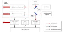
Overview: Wireless optical communication refers to the technology of transmitting information in free space using light beams as carriers, which has the advantages of high bandwidth, low cost, and high security. Due to factors such as narrow signal beam and long transmission distance, it is difficult to establish and maintain a wireless optical communication link. Therefore, an acquisition, targeting, and tracking system needs to be established to prevent the communication link from being interrupted. In the wireless optical communication system, the optical components on the two platforms carrying the transmitter and the receiver are required to be coaxial in real time, and this process is usually called automatic aiming. In order to maintain the real-time aiming of the transceiver boresight of both transceivers, it is necessary to design a fast and high-precision APT system. A typical wireless optical communication APT system is shown in Figure 1. Liu Changcheng established and analyzed the simulation model in the APT system in atmospheric laser communication, and designed an automatic beam capture system; Hu Qidi designed a beacon light spot detection scheme using CCD; Yang Peisong proposed a coaxial aiming detection method, and designed the aiming control system and tracking system according to the method, and carried out field experiments; Zhao Qi designed an initial capture system and conducted a 1.3 km field experiment; Xu Wei designed a light spot detection system and proposed a corresponding image processing algorithm; Li Shiyan proposed an optical axis aiming scheme, which can effectively improve the detection accuracy and aiming accuracy of the system; Yan Xi designed a spot tracking system and conducted a 5.2 km field tracking experiment. The experimental results show that the tracking accuracy of the system can reach 5.4 μrad; Jing Yongkang designed a light spot image detection method, and conducted a 100 km laser communication experiment on this basis; Zhang Pu embedded a high-precision actuator in the APT system to achieve high-precision aiming and tracking, designed a focusing system and conducted field experiments of 10.2 km and 100 km. Liang Hanli designed an APT system that can be mounted on UAVs and conducted an airborne laser communication experiment through a simulated airborne experimental platform, and its tracking accuracy can reach 2.42 μrad; Ke Xizheng, Yang Shangjun and others proposed a fast aiming method. The method does not need to feed back the control signal from the receiving end to the transmitting end, and can complete the establishment of the uplink and the downlink at the same time. And carried out 1.3 km and 10.3 km field experiments to verify the method. This paper systematically analyzes the development and application of the APT system in wireless optical communication and introduces the research progress and achievements of Xi'an University of Technology in this field. Including the experimental analysis and verification of the performance of the designed initial capture system, compound axis control system and beam detection system Improvements have increased the effectiveness and reliability of the APT system.Optical wireless communication refers to the technology of transmitting information in free space using light waves as a carrier, which has the advantages of high bandwidth, low cost, and high security. The acquisition, pointing, and tracking (APT) system is the premise of establishing a wireless optical communication system. A simple, reliable, and dynamic APT system can overcome the impact of mechanical platform vibration and external environment changes on the wireless optical communication system. Therefore, it is necessary to conduct in-depth theoretical and experimental research on the APT system, so as to design a capture, aiming, and tracking method suitable for wireless optical communication. This paper analyzes the domestic and foreign research achievements in capturing, aiming, and tracking, and introduces the work done by Xi'an University of Technology in the field of automatic aiming. It mainly includes the progress of initial acquisition system, non-common visual axis control system, beam detection system, etc. At the same time, the field experiments of 1.3 km, 5.2 km, 10.2 km, and 100 km distance links are introduced to verify the effectiveness of the APT system. Finally, the development of APT in wireless optical communication is prospected.
Aug. 25, 2022Vol. 49 Issue 8 210439 (2022)
Dongya Chu, Guanghui Zhang, Renjie Song, Xiaosong Zhang, Xiaolin Ying, and Yong Li
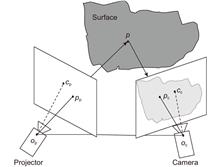
Overview: In the deformation measurement of moving objects with fringe projection, such as the deformation of objects in high-speed flight and the measurement of the unconstrained facial expression changes, we pursue to project as few patterns as possible and obtain as high measurement accuracy as possible. Obtaining the unwrapped phase is one of the key steps in fringe projection 3D measurement, which generally needs the assistance of other information. The common methods are spatial phase unwrapping algorithm, temporal phase unwrapping algorithm, and multi-view geometric constraint. These methods solve the phase unwrapping problem well to some extent, but they have their limitations. The spatial phase unwrapping method is difficult to deal with spatially discontinuous or isolated regions. The temporal phase unwrapping method takes a long time and requires higher hardware at the same measurement speed. The multi-view geometric constraint method reduces the measurement area and increases the complexity and cost of the whole system. In most circumstances, the initial shape of the moving objects can be obtained. According to this fact, a two-step scheme is proposed to improve the performance of dynamic 3D shape measurement. 1) The initial 3D shape of the object and the corresponding 3D coordinates of feature points in the 2D image are obtained by measuring the static object or its CAD model. 2) Carry out the 3D measurement of object motion and change. By detecting the feature points in the dynamic image, the motion parameters of the object at different times are calculated according to the corresponding relationship between 2D and 3D coordinates. Then the approximate shape of the object is estimated from the initial shape. The approximate phase of the fringe pattern at this time is calculated. Then, combined with the approximate phase and the wrapped phase of the actual fringe, the unwrapped phase is calculated, and the 3D shape of the object at that time is obtained. Compared with the temporal phase unwrapping method, the proposed scheme improves the measurement speed under the same measurement reliability. Compared with the spatial phase unwrapping method, this scheme improves the measurement reliability at the same measurement speed and is not affected by fringe discontinuity. A static and dynamic dual-mode 3D measurement system was built by using a DLP projector and high-speed camera. The 3D shape measurement of 1280×1024 points at 70 f/s is realized. The experimental results show that the scheme is feasible and has a large tolerance for the change of the object pose at adjacent times.A two-step scheme is proposed to improve the performance of dynamic 3D shape measurement according to its characteristics. 1) The initial 3D shape of the object and the corresponding 3D coordinates of feature points in the 2D image are obtained by measuring the static object or its CAD model. 2) Carry out the 3D measurement in the process of object motion and change. By detecting the feature points in the dynamic image, the motion parameters of the object at different times are calculated according to the corresponding relationship between two-dimensional and three-dimensional coordinates. Then the approximate shape of the object is estimated from the initial shape. The approximate phase of the fringe pattern at this time is calculated. Then, combined with the approximate phase and the wrapped phase of the actual fringe, the unwrapped phase is calculated, and the 3D shape of the object at that time is obtained. Compared with the temporal phase unwrapping method, the proposed scheme improves the measurement speed under the same measurement reliability. Compared with the spatial phase unwrapping method, this scheme improves the measurement reliability at the same measurement speed and is not affected by fringe discontinuity. A static and dynamic dual-mode 3D measurement system was built by using a DLP projector and high-speed camera. The 3D shape measurement of 1280×1024 points at 70 f/s is realized. The experimental results show that the scheme can measure not only the rigid moving object but also the non-rigid moving object, as long as the fringe change caused by its deformation does not exceed half a period. The proposed method has a large tolerance for the change of object pose at adjacent times as well.
Aug. 25, 2022Vol. 49 Issue 8 210449 (2022)
Jie Ma, and Zhiyong Wu
Overview: In recent years, the number of new photoelectric measurement equipment has increased rapidly, the composition has become more and more complex, the accuracy has gradually improved, and the functions have become more comprehensive. During the normal life cycle of large-scale optoelectronic measurement equipment, engineers seek to maintain the performance of the equipment with the lowest possible cost and as few personnels as possible, so the demand for research on failure prediction and diagnosis technology is increasing. The traditional on-site manual diagnosis and maintenance method requires a lot of manpower and material resources, and it takes a long time to complete a test and diagnosis. The accuracy of the diagnosis is very dependent on the familiarity and experience of the operator. Once a fault occurs, it is difficult to quantify the time for positioning and troubleshooting, which affects the combat effectiveness of the equipment. In fact, major faults that affect the performance of equipment are generally easy to repair in the early stage, but often due to incomplete detection and diagnosis methods, they cannot be detected or cannot be detected on-site in time, resulting in major faults accumulated over time. In the fault diagnosis of photoelectric measurement system, the prediction of tracking error is particularly important. CS-BP algorithm has strong self-adaptive and self-learning ability, and can obtain more reliable results without additional human intervention, so it is often used for fault diagnosis and parameter prediction of large-scale systems. Based on the BP neural network, this article uses the cuckoo algorithm to optimize the threshold and weight, and proposes a CS-BP algorithm. This essay uses the azimuth guidance, pitch guidance, azimuth encoder, pitch encoder and time data of the photoelectric measurement system to predict the tracking error. Compared with the traditional neural network algorithm, the algorithm utilizes the cuckoo's excellent feature of finding extreme values, and solves the problem that the neural network algorithm cannot obtain the optimal solution due to improper initial threshold and weight settings. The experimental results show that compared with the traditional BP neural network and the BP neural network optimized by the genetic algorithm (GA-BP), the number of iterations of the CS-BP algorithm is 21 and 60 times less, and the average relative error of the prediction is 4.85% and 1.57% lower, respectively. Therefore, CS-BP algorithm has a faster convergence speed and higher prediction accuracy, and is suitable for application in fault diagnosis of optoelectronic measurement systems.In recent years, with the increasing number and complexity of photoelectric measurement systems, the demand for fault diagnosis is also increasing. In the fault diagnosis of the photoelectric measurement system, the prediction of its tracking error is particularly important. In this paper, we propose a BP neural network algorithm optimized by the Cuckoo algorithm (CS-BP). The tracking error can be predicted by using the azimuth guidance, pitch guidance, azimuth encoder, pitch encoder and time data of the optoelectronic measurement system. Compared with the traditional neural network algorithm, this algorithm uses the excellent characteristics of Cuckoo to find the extreme value, and solves the problem that the neural network algorithm cannot get the optimal solution due to the improper setting of the initial threshold and weight. The experimental results show that, the number of iterations with CS-BP is 21 and 60 less than the traditional BP neural network and the BP neural network optimized by the genetic algorithm (GA-BP), respectively. The relative errors are 4.85% and 1.57% lower, respectively. Therefore, the CS-BP algorithm has a faster convergence speed and higher prediction accuracy, and it is suitable for fault diagnosis of photoelectric measurement system.
Aug. 25, 2022Vol. 49 Issue 8 210455 (2022)

Zixuan Ding, Ye Chen, and Fei Xu
Overview: Microfibers tapered from conventional optical fibers with diameters ranging from hundreds of nanometers to several micrometers possess various advantages including large evanescent field, strong light confinement, high optical nonlinearity, flexible configurability, and low-loss connection to other fiberized system, which makes it an open platform for miniaturization and integration of all-fiber devices. Nowadays microfiber can be easily obtained through mature fabrication method like flame-brushing technique. On the other hand, as a fundamental opto-electronic component, optical resonators have got comprehensively researched and widely applied in the fields of optical communication, sensing, signal processing, and quantum photonics, including whispering-gallery-mode cavities like micro-ring, micro-cylinder, micro-toroid, and micro-sphere. These traditional optical resonators are fabricated through lithography which is relatively complicated. With the maturation of microfiber fabrication methods, optical resonators based on optical microfibers have been demonstrated and developed, such as microfiber loop resonators, microfiber knot resonators, and microfiber coil resonator. As an optical coupling device based on evanescent field coupling, the microfiber resonator features in low insertion loss, high Q-factor, high finesse, excellent mechanical stability, easy fabrication process, and compatibility with fiber systems, providing a broad platform for all-fiberized miniatured devices of probing and modulation. Through further integration with exterior functional materials and microfabrication techniques, a microfiber resonator can be utilized in diverse domains of sensor, filter, modulator, and fiber laser, as well as quantum photonics and nonlinear optics, realizing the ‘lab on fiber-ring’. In the field of sensing, the microfiber resonators get exploited as the refractometric sensor, concentration and humidity sensor, temperature and current sensor, mechanical pressure sensor, microfluidic sensor, magnetic field sensor, acceleration sensor, etc., where the devices exhibit high adaptability and excellent sensitivity. As to optical signal processing, the device can be used as the single wavelength or multi-wavelength filter, code-type conversion, and optical modulation. The intensity and phase of light can be tuned to a large scale within broad wavebands, and the modulation response time is also reduced to achieve high-speed modulation. Furthermore, the microfiber resonator can be used as an optical delay line or generator of second harmonic or third harmonic. When applied into fiber laser, the microfiber resonators help build the stable light source with narrow linewidth single frequency or multiwavelength laser with high uniformity. The devices integrated with metal or 2D materials also make the laser operate under conventional soliton mode-locking or dissipative four-wave-mixing mode-locking regime and output sub-picosecond pulsation, broadening the dynamics of ultrafast optics. In this article, we summarize the recent progress in the microfiber resonators research fields, covering fundamental principles and characteristics, fabrication methods, and applications of microfiber resonators.Microfibers tapered from conventional optical fibers with diameters ranging from hundreds of nanometers to several micrometers possess various advantages including large evanescent field, strong light confinement, high optical nonlinearity, flexible configurability, and low-loss connection to other fiberized systems, which makes it an open platform for miniaturization and integration of all-fiber devices. As a fundamental opto-electronic component, optical resonators have got comprehensively researched and widely applied in the fields of optical communication, sensing, signal processing, and quantum photonics. Traditional optical resonators are fabricated through lithography which is relatively complicated. With the maturation of microfiber fabrication methods, optical resonator based on optical microfibers was demonstrated and developed. As an optical coupling device based on evanescent field coupling, the microfiber resonator features in low insertion loss, high finesse, easy fabrication, and compatibility with fiber systems. It can be utilized in domains of filter, sensor, modulator, and fiber laser. In this article, we summarize the recent progress in the microfiber resonators research fields, covering fundamental characteristics, fabrication methods, and applications of microfiber resonators.
Aug. 25, 2022Vol. 49 Issue 8 220006 (2022)

Liangzong Zhang, Tao Yang, Yun Wu, and Tao Tang
Overview: It is a trend of development to use the Stewart platform as a means of space. But the Stewart platform, which has a vibration ability and low system bandwidth, causing the tracking accuracy to be difficult to improve. In response to this problem, many scholars have proposed a two-stage control system, which is to design the system of a system that is far higher than the Stewart platform, which is used to curb the tracking error of the Stewart platform, thereby improving the tracking accuracy of the system. Tip-tit-mirror (TTM) bandwidth is very high, available in the intensive subsystem and the Stewart platform for two-stage control. When the system has only one CCD as a detector, it is necessary to design the decoupling link to make the system stable. But for the traditional two-order structure, it is difficult to design the decoupling element as the object of the probe. Therefore, this paper analyzes the traditional two-order structure and removes the redundant control structure. This paper also obtains the new structure based on the two-stage control of the position output and makes the decoupling link becomes easy. Through theoretical analysis, the accuracy of the system is mainly due to the ability of the precision subsystem to suppress the error of the rough system. The traditional controller of the advanced subsystem is the PI controller, which is extremely limited to the accuracy of the precision. The current research on the accuracy of the TTM tracking accuracy is mainly by introducing additional hardware devices, but this increases the uncertainty of the system stability. Therefore, the design of the PI-PI controller can effectively improve the tracking accuracy while increasing the cost of the system. After theoretical analysis and experimental verification, the PI-PI controller, compared to the PI controller, can improve the suppression ability of the error of the precision subsystem in the low frequencies. The double order structure control of the system and the Stewart platform is made up of the system, which makes the tracking precision of the system significantly improved, which is better solved the problem of the Stewart platform tracking precision that has the vibration function.The Stewart platform has six degrees of freedom motion characteristics and can be used as both vibration isolation and tracking platform. However, the vibration isolation function requires low system bandwidth, while the tracking function requires high system bandwidth, which makes it difficult to achieve high precision tracking using the Stewart platform with vibration isolation function. To solve this technical problem, a high-bandwidth tilt correction system is introduced to form a two-stage control structure, so as to improve the accuracy. The traditional two-stage control needs to design decoupling link and independent measurement sensors to achieve hierarchical control. In this paper, a control method based on a single sensor is proposed to improve the traditional dual-order structure to avoid decoupling and achieve a high-precision closed-loop for the Stewart-TTM. In order to further improve the tracking accuracy of the system at low frequencies, a PI-PI controller is designed. Theoretical analysis and experimental verification show that the Stewart dual-stage control structure based on image measurement can not only meet the requirements of vibration isolation, but also achieve high-precision tracking control. Compared with the traditional PI controller, the PI-PI control proposed in the tilt correction system can effectively improve the tracking accuracy.
Aug. 25, 2022Vol. 49 Issue 8 220019 (2022)

© Copyright 2018-2021 | Chinese Laser Press.
All Rights Reserved 沪ICP备15018463号-20