


Three-dimensional (3D) inorganic micro and nanostructures play an important role in photonics, quantum information, aerospace, energy, and other fields. Inorganic microstructures prepared using traditional methods usually exhibit low resolution and uncontrollable morphology. The precise and controllable fabrication of 3D inorganic micro and nanostructures is a critical problem. Because of advantages such as 3D fabrication capability, high precision, and controllable morphology, laser fabrication can realize the preparation of 3D, high-resolution, and multiscale micro and nanostructures; furthermore, it can address the problem of accurate and controllable preparation of these 3D structures. In this study, the research progress of laser fabrication of inorganic micro and nanostructures was reviewed. First, continuous wave and ultrafast pulse laser fabrication methods were discussed, and especially, the femtosecond laser fabrication of 3D inorganic microstructures and nanostructures, including pure inorganic material systems, organic-inorganic hybrid systems, and polymer templates, were summarized. Further, the applications of 3D micro and nanostructures in optical devices, quantum chips, information storage, aerospace, and bionic structures in recent years were summarized. Finally, we highlighted the potential future development of the laser fabrication of 3D inorganic micro and nanostructures.
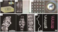
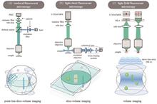
The restricted optical aperture and limited measurement bandwidth of microscopy impose constraints on information acquisition, particularly during the observation of dynamic processes within fine subcellular structures and ultrafast and transient biological events in vivo, and efficient three-dimensional imaging of mesoscopic ex vivo tissues within biological systems. This limitation represents a formidable hurdle in the landscape of multidisciplinary biomedical research. Traditional constraints associated with fluorescence microscopy have prompted studies on innovative principles and methodologies. By integrating artificial intelligence, efforts have been directed toward enhancing the speed and precision of fluorescence microscopy imaging, thereby augmenting information throughput. In this study, a meticulous analysis of problems posed by throughput limitations encountered in the fields of cell biology, developmental biology, and tumor medicine. Through the integration of artificial intelligence, traditional constraints associated with fluorescence microscopy throughput were surmounted. This pioneering approach paves the way for the advancement of physical optics and image processing and greatly contributes to the evolution of biomedical research. This study offers comprehensive insights into intricate phenomena within the realms of life and health, not only holding paramount importance for biomedical exploration but also unveiling promising avenues for future studies and applications.
ObjectiveLaser and electrochemical hybrid machining is a composite processing method that combines laser and electrochemical processing. It can be used to process hard conductive materials. It can accelerate the electrochemical dissolution rate, avoiding recasting layers, thus improving the surface quality. This study proposes a tubular electrode-coupled laser and electrochemical hybrid machining technology that uses a newly designed tubular electrode. This realizes coaxial transmission of laser and electrochemical energy inside the tubular electrode and controllable coupling at the processing gap, which is suitable for high-quality small hole processing with a high aspect ratio. A coupling mechanism dominated by laser and an electrochemical processing is proposed based on the controllable adjustment of the laser and electrochemical energy at the processing gap. The effects of the temperature rise in the laser irradiation zone on the electrolyte conductivity, current density, liquid-phase mass transfer, and electrochemical dissolution rate, as well as the effects of bubbles and impurities generated during electrolysis on the laser energy. Material removal models for laser and electrochemical hybrid machining are established, and preliminary simulation analysis and experimental research on laser and electrochemical hybrid machining are conducted.MethodsThis study introduced a tool for laser and electrochemical hybrid machining with a tubular electrode that confined the electrolyte and laser beam coaxially or asynchronously. In addition, it utilized a coaxial optical fiber inside the tubular electrode to enable total internal reflection of the laser, thereby achieving independent control of laser and electrochemical energy within the tubular electrode. Based on this process, a coupling mechanism for the laser and electrochemical energy was explored, as well as the mechanisms where the laser and electrolysis dominate in the hybrid machining process. By investigating the temporal and spatial distributions of local temperature and stress induced by coupled energy, we study the influence of laser on mass transport and electrode potential in the micro-region of electrochemical machining. A theoretical model for the kinetic behavior of materials removal under the action of hybrid energy was established, and a preliminary simulation analysis of laser and electrochemical hybrid machining was conducted. The results of this study laid a theoretical foundation for the fabrication of complex structures with high quality and aspect ratio.Results and DiscussionsFirst, the influence of laser power density on the machining capability of workpiece materials is explored (Fig.2). When the laser power density is low, the laser affects the thermal and electrochemical parameters of the workpiece material and the changes in the electrolyte's electrical conductivity, electrolytic current density, ion diffusion rate, bubble rate, and electrode potential within the machining gap through thermal effects. When the laser power density reaches the electrolyte breakdown threshold, the laser impacts the laser and electrochemical hybrid machining process through both thermal and mechanical effects. Second, based on the controllable adjustment of the laser and electrochemical energy within the tubular electrode, the state changes in the coupling region caused by these energy are classified into three mechanisms: laser-assisted electrochemical machining, laser and electrochemical hybrid machining, and electrolysis-assisted laser machining (Fig.4). Furthermore, through theoretical analysis and preliminary simulation studies, the electric field and current density distributions in the laser and electrochemical hybrid energy field, the flow field distribution, the temperature distribution, and the resulting machining surface are investigated. This facilitates in the evaluation of material removal at different locations on the workpiece during the laser and electrochemical hybrid machining processes. Finally, three-dimensional morphologies of blind holes produced by the only electrochemical machining and laser and electrochemical hybrid machining are compared. The advantages of the hybrid laser and electrochemical processing are confirmed (Fig.9). It successfully manufactures through-holes with a diameter of 1.26 mm and a high aspect ratio of 16∶1 and through-holes with a diameter of 1.25 mm and high aspect ratios of 42∶1 (Figs.10 and 11).ConclusionsLaser and electrochemical hybrid machining typically suffer from defects such as stray corrosion caused by electrochemical machining and resolidification defects caused by laser machining. To avoid the occurrence of defects and improve the surface quality, this study introduces a tool for laser and electrochemical hybrid machining with a tubular electrode. This enables the coaxial transmission of laser and electrochemical energy within the tubular electrode and the controlled coupling at the machining gap, thereby effectively preventing defects such as stray corrosion and resolidification of layers. This approach is suitable for fabricating complex structures with high quality and aspect ratios. Based on the controllable adjustment of the laser and electrochemical energy, this study proposes mechanisms in which laser and electrolysis dominate, and both cooperate in hybrid machining. The thermal effects of the laser on the laser and electrochemical hybrid machining and the influence of the pulse width of electrolysis on the process are analyzed. This study establishes a theoretical model for the kinetic behavior of material removal under the action of hybrid energy. Preliminary investigations are also conducted on the time and spatial distribution of the hybrid energy field and its impact on the machining surface using simulation models. Through experiments, the advantages of laser and electrochemical hybrid machining are verified. Small holes with a diameter of 1.25 mm and aspect ratio of up to 42∶1 without resolidified layers are successfully produced. This study lays a theoretical foundation for the fabrication of complex structures with high quality and aspect ratio.

ObjectiveHybrid material structures have various applications in the automotive industry owing to their light weight. Stainless steel, which exhibits good corrosion resistance and remarkable mechanical properties, is widely used in automotive applications. Glass fiber reinforced plastics (GFRPs) that exhibit high specific strength and cost performance have replaced existing materials in applications requiring lightweight materials. Single-side resistance spot welding of stainless steel and GFRP can help combine the advantages of the two materials. However, owing to the difference in the thermal physical properties and chemical structures of these two materials, the combined strength cannot meet industrial requirements. Improving mechanical interlocking and chemical bonding is an effective approach for enhancing the joint performance. The laser joining process can be used to fabricate micro-textures and change the surface chemical state. Thus, micro-textures on the surface of stainless steel are prepared using a nanosecond laser, and the strengthening mechanism of the interface under the influence of the micro-textures is studied.MethodsInitially, 304 stainless steel and GFRP are selected as base materials. The 304 stainless-steel sheets are subjected to laser texturing. The cruciform mesh micro-texture is selected as the basic morphology of the stainless-steel surface. The grid line uses contained multiple equally spaced scan lines, and a laser processing system supporting software is used to preset different micro-texture widths. The number of laser scanning times is set as 10, and the micro-texture width is set as 0.1?0.5 mm. An optical digital microscope and a field-emission scanning electron microscope are used to detect the laser texture, surface morphology, and fracture surface of the joint. A constant-temperature heating platform and a high-temperature wetting angle measurement system are used to measure the GFRP contact angle on the stainless-steel surface to characterize its wettability. A universal material testing machine is used to conduct tensile-shear tests on the 304 stainless steel/GFRP single-side resistance spot welding joints.Results and DiscussionsThe introduction of micro-textures on the surface of stainless steel significantly improves the wettability of the surface. The surface of stainless steel changes from an untreated non-wetting state to a wet state after laser treatment. As the width of the micro-texture increases, the wettability initially increases and then decreases (Fig. 5). When the micro-texture width is 0.2 mm, the wettability reaches the optimum value. The interior of the micro-textures is completely filled with molten GFRP. When the micro-texture width is too large, the molten GFRP cannot completely fill the interior of the micro-textures (Fig. 7). C and Fe diffuse at the interface, and an element diffusion layer is formed (Figs. 8 and 9). When the micro-texture width is 0.2 mm, the tensile-shear force reaches the maximum value of 3548 N, which is 385% higher than that of the untreated stainless steel/GFRP single-side resistance spot welding joint. The tensile-shear force first increases and then decreases as the micro-texture width increases. Compared with the case of the joint without micro-textures, after laser treatment of the stainless-steel surface, a large amount of the resin-glass fiber mixture is observed in the center area of the fracture of the joint (Fig. 11). The fracture mode changes from an interfacial fracture to a mixed form of interfacial and cohesive fractures. Corresponding to the wettability and joint tensile-shear force, the bonded-area ratio first increases and then decreases, indicating an improvement in mechanical properties.ConclusionsLaser texturing is used to improve the performance of stainless steel/GFRP single-sided resistance spot welding joints. After the nanosecond laser treatment, the wettability of the molten GFRP on the stainless-steel surface is significantly improved, and the state changes from non-wetting to wetting. The introduction of the micro-textures improves the mechanical properties of the stainless steel/GFRP resistance spot welding joint. When the micro-texture width is 0.2 mm, the tensile-shear force of the stainless steel/GFRP single-side resistance spot welding joint reaches the maximum value of 3548 N. Compared to the case wherein the micro-textures are not introduced, the tensile-shear force of the textured joint is 731 N. The introduction of the micro-textures increases the contact area between the stainless steel and GFRP, thereby significantly enhancing mechanical interlocking. When the micro-texture width is suitable, the GFRP completely fills the inside of the micro-textures. When the micro-texture width is too small or too large, the GFRP does not completely fill the inside of the micro-textures owing to the influence of wettability. In addition to mechanical interlocking, Fe and C chemically diffuse at the interface to form a compound layer, which further improves joint strength.
ObjectiveTitanium matrix composites have attracted considerable attention because of their high modulus of elasticity, high specific strength, high wear resistance, and excellent high-temperature durability. Most studies on titanium matrix composites (TMCs) focus primarily on the in-situ formed TiC reinforced composites. However, few studies have focused on the direct addition of TiC-reinforced titanium matrices. The manners in which the size, morphology, and distribution of TiC evolve during the SLM process and how they affect the microstructure and mechanical properties remain unclear. In this study, TiC/TC4 composites with directly added nanoscale TiC particles are successfully prepared by selective laser melting (SLM), and the microstructure evolution under different volume energy densities is investigated. Further, the TiC evolution during SLM and its influence on the microstructure and microhardness are analyzed. Thus, the findings of this study can provide the support for SLM preparation of titanium composites.MethodsHerein, nanoscale TiC (diameter of 50?150 nm) and TC4 are selected as the reinforced phase and matrix, respectively. The composite powder with TiC uniformly embedded on the surface of the TC4 powder is obtained by low-energy ball milling. Subsequently, the TiC/TC4 composites are prepared via SLM with different volume energy densities (29?97 J/mm3). The forming quality and microstructures at different volume energy densities are observed using optical microscopy (OM) and scanning electron microscopy (SEM) equipped energy disperse spectroscope (EDS). The grain size and crystal orientation are investigated using electron backscattering diffractometer (EBSD), and the phase compositions are measured using X-ray diffraction (XRD). Finally, the microhardness is measured using a digital microhardness tester.Results and DiscussionsThe optimized volume energy densities for the SLM formed TiC/TC4 composites are in the range of 50?70 J/mm3, with a relative density of 99.7% (Fig.3). Owing to the enrichment of TiC in the melt pool boundary zone, the microstructure of the composites exhibits a special double-sized grain distribution in the cross section (Fig.6). Owing to the rapid cooling characteristics of the SLM process, TiC cannot be sufficiently dissolved. Therefore, the SEM and EBSD results reveal three types of reinforcement: undissolved TiC, eutectic TiC, and precipitated TiC. Undissolved TiC is distributed primarily at the boundaries of coarse β equiaxed grains, eutectic TiC is distributed primarily in the boundaries of irregular eutectic β grains, and precipitated TiC is distributed primarily in the grains. With an increase in volume energy density, the chain-like eutectic TiC gradually transforms to rod-like eutectic TiC (Figs.7 and 8), the size of precipitated TiC inside the grain gradually increases, and the sizes of longitudinal and transverse α'-Ti gradually increase.ConclusionsThe optimal volume energy density for the formation of TiC/TC4 composites by SLM is 50?70 /mm3, and the relative density is 99.7% within this parameter range. TiC is enriched in the melt-pool boundary region under a strong temperature gradient and Marangoni convection. The microstructure of the composite has a special double-size grain distribution in the cross section, consisting of primary β equiaxed grains and irregular eutectic regions growing on the periphery. In the longitudinal section, the molten pool is a fish scale, and some chain structures exist in the molten pool that grow from the direction of heat flow to the horizontal direction. With an increase in volume energy density, the size of primary β equiaxed grains decreases, outer-ring irregular eutectic region expands, and morphology of fish scales becomes sharp. The microhardness initially decreases and then increases, essentially reaching 385?392 HV in the optimal molding process window. TiC in the composites is composed primarily of undissolved TiC (distributed near the primary β grain boundaries), eutectic TiC (distributed in the eutectic β grain boundaries in a chain or rod-like network), and precipitated TiC (distributed in the grain in a granular manner). With an increase in volume energy density, the difference in TiC size and quantity inside and outside the molten pool increases, chain distribution of eutectic TiC changes to rod, and the size of TiC in the grains increases. Further, no obvious orientation relationship between eutectic TiC and β-Ti is observed; however, a distinct orientation relationship between eutectic and in-grain TiC and α'-Ti exists: {11?20} α'-Ti∥{110}TiC.
ObjectiveDuctile iron has been extensively used in various automotive components such as crankshafts and differential housing owing to its relatively low density and capacity for significant tensile strength. 20MnCr5 is a robust and tough alloy steel commonly employed in the production of gears and shafts. Establishing effective welding between the shaft body and the gear material is a significant research challenge. However, the notable disparity in the thermal properties between ductile iron and alloy steel hinders the performance of the welding joint. The high carbon content of ductile iron promotes carbon segregation at the welding interface and exacerbates the formation of microcracks, thereby considerably increasing the complexity of the welding process. Owing to its high energy density, laser welding offers the advantage of generating welds with more precise heat-affected zones. In this study, a novel continuous-pulse coaxial dual-beam laser is employed as a welding heat source to enhance the surface quality of the weld seam. The high-quality welding of ductile iron and alloy steel is achieved by decreasing the laser input power and diminishing pore formation. We hope that our novel welding strategy and findings will be helpful in understanding the bonding mechanism of ductile iron and alloy steel and provide more application space for their connectors.MethodsIn this study, QT500-7 and 20MnCr5 are employed as the base materials, with ERNiCr-3 as the filling wire. A novel continuous-pulse dual-beam laser is used as the heat source. First, the pulsed laser power is varied with a constant continuous laser power to determine the optimal combination of heat sources. The laser action position is then adjusted to further enhance the weld strength. Microstructures are observed using a metallographic microscope, and mechanical performance testing and analysis are conducted using a tensile testing machine. The microhardness of the weld is measured using a microhardness tester. Additionally, the fracture behaviors of different specimens are analyzed using a field-emission scanning electron microscope.Results and DiscussionsThe use of a continuous-pulse coaxial dual-beam laser as a welding heat source (Fig. 2) produces high-quality welding joints. When the pulsed laser power is varied, the weld formation varies considerably (Fig. 4). The weld seam is found to have no defects, such as cracks or pores. When the laser action position shifts toward the steel side, the heat input on the ductile iron side gradually decreases. This reduction in the heat input suppresses the diffusion of carbon, leading to a significant decrease in the hardness values of the heat-affected and bond zones on the QT500 side (Fig. 13). The cross-sectional morphology of the weld reveals significant changes in the melting amount of the QT500-7 side base material, with the centerline shifting toward the ductile iron side when the laser action position is changed (Fig. 6). The segregation line of carbon caused by the high carbon content of the nodular cast iron is solved by changing the laser position to reduce the heat input on the side of the nodular cast iron (Fig. 7). The best mechanical properties of the joint are obtained under a pulsed laser power of 440 W and offset of 0.2 mm. In summary, a continuous-pulse coaxial dual-beam laser can yield high-quality welding joints. Better dual-beam laser welding parameters can be achieved by adjusting the laser power and action position. Furthermore, carbon segregation issues can be effectively resolved by reducing the heat input on the side of the nodular cast iron by changing the laser action position, and pulsed laser stirring proves useful.ConclusionsIn this study, a coaxial dual-beam laser welding technology is proposed to address the challenges of welding ductile iron QT500 and alloy steel 20MnCr5. The main problems are the precipitation of martensite and ledeburite in the heat-affected and bond zones on the QT500 side, which results in carbon segregation. The pulsed laser power and position are adjusted in this study. When the laser action position is shifted toward the steel side, the decreased heat input suppresses the diffusion of carbon, leading to a significant decrease in the hardness of the heat-affected and bond zones on the QT500 side. The best mechanical properties are achieved under a pulsed laser power of 440 W and laser offset of 0.2 mm. The continuous-pulse coaxial dual-beam laser welding technology not only improves the carbon segregation phenomenon on the ductile iron side but also reduces the formation of welding cracks. Overall, the proposed novel coaxial dual-beam laser welding technology is effective in improving welding quality, specifically for ductile iron and alloy steel dissimilar metals. The joint exhibits high-quality and high-performance characteristics by reducing carbon segregation and minimizing hardness values. This study advances the field of welding and provides a potential solution for the welding of dissimilar metals with different material properties.

ObjectiveWith the rapid development of the aerospace, ship, power, and energy fields, single-crystal Ni-based superalloys have been widely used in aeroengine and gas turbine components because of their excellent comprehensive performance. This has resulted in an increase in the quality requirements for related microhole structures, which has translated to higher processing technology requirements. Waterjet-guided laser drilling technology, when compared with other traditional microhole processing techniques, such as electrochemical machining, electrical discharge machining, and “dry laser” processing, has the advantages of a large working distance, no thermal damage, neat cutting, and no obvious taper. However, the high specific strength and low thermal conductivity of single-crystal Ni-based superalloys make them prone to defects such as poor microhole surface morphologies and large tapers during processing. Hence, it is crucial to investigate the effects of the processing parameters on the microhole surface morphologies and taper for high-quality machining of superalloy microholes.MethodsThis study investigates the mechanism and experimental research of waterjet-guided laser drilling of the single-crystal Ni-based superalloy, DD91. First, the effects of the laser single-pulse energy, scanning speed, feed time, and scanning time on the surface morphologies and tapers of microholes are studied by setting up single-factor experiments. Then, based on the single-step spiral scanning mode [Fig.2(a)], a multistep spiral scanning mode drilling method [Fig.2(b)] is proposed to improve the defects of poor microhole surface morphologies and large tapers. In the multistep spiral scanning mode, the coupled energy beam repeatedly scans the innermost circle (circle 1) N times, cut across the material to form a prefabricated hole at the center of the microhole, and then scans the second circle (circle 2) to the outermost circle (circle N) N times with a single-step spiral scanning mode to complete the processing of the filling circle and hence widen the aperture and improve the microhole geometry. Finally, the quality of microhole machining via the single/multistep spiral drilling methods is compared under the appropriate processing parameters. The microhole surface morphologies are observed using optical microscope, the entrance and exit apertures are measured via ultra-depth-of-field microscope, and the corresponding taper is calculated.Results and DiscussionsDuring waterjet-guided laser trepanning on metals, material removal is dominated by laser ablation through mechanisms such as photothermal mechanisms, including material melting, evaporation, and sublimation. The water jet, with its high heat capacity, can provide good heat management as well as clean molten material and debris from the ablation zone (Fig.3). As the laser single-pulse energy increases, the material removal rate also increases, which enlarges the exit diameters and causes the taper to increase (Fig.5). A pulse energy that is too low will lead to serious microhole surface morphology damage (Fig.4). With an increase in scanning speed, the ablation time per unit area decreases, which leads to a worsening of the circularity of the hole (Fig.7), a decrease in the exit diameter, and an increase in the taper (Fig.6). As shown in Fig. 9, the entrance diameters of the microholes are all steady at approximately 1025 μm, regardless of how many feeds are applied. The exit diameters increase with an increasing number of feeds and reach a saturation value (approximately 1000 μm) after the feed time is over 6 (Fig.9). Multiple feeds can improve the circularity of the microhole (Fig.8). When the scanning time is 1, the microhole taper is smallest, but the dimensional accuracy is low. With an increase in the scanning times, the quality of the microhole deteriorates, the entrance aperture decreases linearly, the exit aperture first decreases and then becomes saturated, and the taper of the microhole first increases and then decreases (Figs.10 and 11). Based on the above results, the appropriate processing parameters are selected to compare the quality of microhole machining via the single/multistep spiral drilling methods. The surface morphologies and taper of the microhole processed using the multistep spiral drilling method are obviously improved (Fig.12 and Table 2). This is because a prefabricated hole at the center of the microhole can discharge debris and water from the bottom of the hole, reduce the interference with laser transmission, and improve the surface morphologies and taper of the microhole.ConclusionsThe variations in the laser single-pulse energy, scanning speed, feed time, and scanning time on the surface morphologies and taper of microholes using the single spiral drilling method are investigated. A multistep spiral scanning mode drilling method is proposed to improve the defects of poor microhole surface morphologies and large tapers caused by the single-step spiral scanning mode. The quality of microhole machining using the single/multistep spiral drilling methods is compared under appropriate processing parameters. The experiments indicate that increasing the single-pulse energy and reducing the scanning speed can improve the surface morphology of microholes and reduce the microhole taper. With an increase in the feed times, the surface morphology of the microhole gradually improves, and the microhole taper initially decreases and then saturates. As the number of scanning rounds increases, the surface morphology of microhole gradually deteriorates, and the microhole taper first increases and then decreases. The taper of microholes processed using the multistep spiral method is only 0.29°, which is a 70% reduction compared to that using the single-step spiral method, and the dimensional deviation and roundness are controlled within 20 μm.
ObjectiveIn recent years, laser additive manufacturing based on direct laser deposition has attracted widespread attention because of its flexibility and efficiency. This technology has a wide range of applications and high additive manufacturing efficiency. It is widely used in the aerospace, rail transit, and ship component maintenance equipment fields. However, high-strength aluminum alloys such as those in the Al-Zn-Mg-Cu series have a high content of alloying elements. During the solidification process, the semi-solid range of the alloy may exceed 100 ℃, which can easily leave gaps between aluminum grains. The α-Al layer of "liquid film" generates cracks under the action of thermal stress, making laser deposition repair difficult. AlSi10Mg alloy, as a cast aluminum alloy, has the characteristics of a short semi-solid range and high strength, and is suitable for additive manufacturing and the laser repair of high-strength aluminum alloy components. However, during the laser deposition process, process fluctuations often cause defects such as pores to appear in the components, leading to cracks and ultimately component failure during use. Therefore, exploring a method to eliminate pores in components produced using AlSi10Mg laser deposition is of great significance for improving the mechanical properties and service life of AlSi10Mg components.MethodsAtomized AlSi10Mg alloy powder with a particle size ranging from 53 μm to 150 μm is adopted. During the laser deposition process, the laser power is 2700 W, deposition speed is 600 mm/min, powder feed rate is 5.8 g/min, overlap amount is 2.5 mm, argon flow rate is 5 L/min, and protective argon amount is 20 L/min, resulting in a single-layer thickness of 0.5 mm. After depositing eight layers to achieve a thickness of 4 mm, stir friction treatment is performed on the deposited AlSi10Mg alloy. The height of the mixing needle of the mixing head is 4 mm, with a four-prism shape and diameter of 6 mm at the end of the prism. During the stirring friction treatment process, the rotational speed is 800 r/min, stirring speed is 100 mm/min, and variation in the stirring friction treatment passes is 5 mm. Subsequently, the laser deposition of eight-layer AlSi10Mmg alloy is continued on the surface of the AlSi10Mg alloy after the stir friction machining, and then stir friction machining is used.Wire cutting is used to cut the AlSi10Mg alloy into five samples, and stir friction-assisted laser deposition is conducted, followed by room-temperature rolling treatment. Rolling deformation values of 20%, 46%, and 68% are achieved on three of the samples. The five tensile specimens of the AlSi10Mg alloy are treated as mentioned above, and their strength and elongation values are measured using a tensile testing machine. After vibration polishing, the five metallographic samples are observed using a scanning electron microscope and backscattered electron diffractometer, and their microhardness values are measured. A thin film sample of the AlSi10Mg alloy is prepared and its microstructure is observed using a transmission electron microscope after electrolytic double spraying. The fracture of the tensile specimen is observed using the scanning electron microscope.Results and DiscussionsThe hardness values of the AlSi10Mg alloy in the five different states are listed in Table 1. It can be observed that the hardness of the deposited AlSi10Mg alloy is approximately 109 HV. Because at high temperatures, the solid solubility of the Si element in the α-Al matrix is relatively high, and when the temperature rapidly drops, it is difficult for the Si element to recover from α-Al matrix, and a large number of Si atoms on α-Al matrix play a role in solid solution strengthening. The Al matrix plays a role in solid solution strengthening. After stir friction processing, the solid solution strengthening effect is significantly weakened, and the hardness of the AlSi10Mg alloy decreases to 75 HV. Based on the hardness values of the rolled AlSi10Mg specimens listed in Table 2, it can be observed that the rolling process improves the effects of dislocation strengthening and fine grain strengthening in the AlSi10Mg alloy, ultimately increasing the hardness of the laser-deposited AlSi10Mg alloy after stir friction processing to 116 HV. As shown in Fig. 9, after stir friction processing, the strength of the AlSi10Mg alloy is close to 200 MPa, and the elongation distribution is 33%?40%. It can be seen that stir friction processing can simultaneously improve the strength and plasticity of the laser-deposited AlSi10Mg alloy. Figure 10 shows that there are a large number of dimples in the tensile fracture surface of the AlSi10Mg alloy in the laser deposition state and stir friction processing state, indicating that the fracture mode of both AlSi10Mg alloy specimens is the plastic fracture mode. The research on hardness shows that the strength and elongation of the laser deposited AlSi10Mg alloy cannot reach high levels. However, after stir friction processing, the larger shoulder pressure and stirring effect eliminate the porosity defects in the alloy, reduce the stress concentration, and thus significantly increase its elongation.ConclusionsAfter friction stir processing, the columnar α-Al and eutectic phases in the laser deposited AlSi10Mg become equiaxed α-Al grains and Si particles, while the Mg2Si precipitate phase is significantly refined. After rolling, when the deformation of the AlSi10Mg alloy increases to 68%, dislocation strengthening further refines the grains.After rolling, the dislocation strengthening effect in the alloy is significantly enhanced. In addition, increasing the rolling amount also brings about a fine grain strengthening effect. Therefore, the hardness of the AlSi10Mg alloy can be increased to 116 HV at most, exceeding the microhardness of the laser deposited AlSi10Mg alloy.Although the solid solution strengthening effect in the laser deposited AlSi10Mg alloy is remarkable, the solidification defects in the alloy lead to the formation of early cracks during the tensile process, which results in an alloy strength of less than 200 MPa and an elongation of less than 20%. After friction stir processing, the strength and toughness of the AlSi10Mg alloy are simultaneously improved, with a strength close to 200 MPa and an elongation of 33%?40%. After rolling, the dislocation strengthening effect of the AlSi10Mg alloy gradually increases, and its strength continues to rise, reaching a maximum of approximately 400 MPa. The localized hardening area in the alloy leads to a decrease in its plastic deformation ability, and the elongation gradually decreases to 25%.
ObjectiveSelective laser melting (SLM) technology offers a wide range of design freedom, high density, and strong metallurgical bonding; thus, it is highly suitable for processing workpieces with complex shapes. A conformal cooling mold formed via SLM can improve the cooling efficiency and decrease the injection cycle time. However, only a few types of mold steel materials are suitable for 3D printing because of long processing time and high costs. First, conventional processes can be employed to manufacture conventional parts; subsequently, complex parts can be built using SLM. With this approach, the manufacturing efficiency can be improved and costs can be reduced. In this study, a new type of 3D printing die steel material (AM40) is deposited on a commercial H13 substrate using SLM. The effects of heat treatment (HT) on the microstructure and mechanical properties of AM40/H13 bimetallic structural materials are studied, and the deformation and cracking behaviors of the bimetallic molds are revealed.MethodsIn this study, AM40 steel powder and annealed H13 steel sheets are used. SLM is used to deposit AM40 onto the H13 substrate. Subsequently, quenching and tempering are performed to study the effects of the heat treatment. The particle size distribution is characterized using a laser particle size analyzer, whereas the microstructure and fracture morphology are characterized using optical microscope (OM) and scanning electron microscope (SEM). The grain morphology, orientation, and local misorientation of the bonding interface are characterized using electron backscatter diffraction (EBSD). Additionally, a Vickers microhardness tester is employed to measure the microhardnesses of the as-built and heat-treated samples. Tensile tests are performed using a fatigue testing machine.Results and DiscussionsNo crack defect is observed at the interface of the as-built AM40/H13 bimetallic structure and the unique Marangoni molten pool at the interface (Fig. 7). Moreover, fine cellular and columnar martensite structures are observed in the AM40 region (Fig. 8). The microstructure of H13 is coarsened austenite (Fig. 5), and the distinct microstructural inhomogeneity is observed at the bonding interface. After quenching and tempering, the characteristics of the molten pool disappear, and uniform lath martensite microstructures form in the H13 region (Fig. 8). The inhomogeneity of the grain size and misorientation at the interface are eliminated (Fig. 10). Moreover, the diffusion width of element at the interface increases from 440 μm to 500 μm (Fig. 9). Additionally, the hardness of the as-built AM40/H13 at the bonding interface is 642 HV, which is higher than those of AM40 (529 HV) and H13 (202 HV). The average hardness of HT-AM40/H13 at the bonding interface decreases to 480 HV (Fig. 11), thus indicating that the hardness difference between AM40 and H13 is eliminated by the heat treatment. The tensile strength of HT-AM40/H13 increases significantly from 644 MPa to 1436 MPa (Fig. 12). Furthermore, some dimples, along with a cleavage pattern, are observed in the fracture (Fig. 14), thus indicating that the fracture mode is a combination of ductile and brittle. The increase in the tensile strength and ductility of the heat-treated AM40/H13 bimetallic alloy is analyzed based on the microstructure and fracture morphology of the bonding interface.ConclusionsIn this study, the as-built AM40/H13 bimetallic structure does not exhibit crack defects at the interface, and the microstructure is heterogeneous. Marangoni convection and cellular and columnar structures are observed in the weld pool at the interface. The alloying elements are evenly distributed at the interface, thus indicating good metallurgical bonding. After heat treatment, the grain size and dislocation density near the interface are similar, thus eliminating the inhomogeneity of the interface structure. The elements at the interface diffuse, and the diffusion width increases by 60 μm. The hardness at the as-built AM40/H13 bimetallic H13 side is the lowest (202 HV), followed by that at the AM40 side (529 HV); by contrast, the interface hardness is the highest (642 HV). Tensile deformation and cracking of the bimetal preferentially occur at the H13 side, with a strength of 644 MPa and fracture elongation of 29%, thus indicating ductile fracture. After heat treatment, the hardness of H13 increases to 483 HV, which is equivalent to that of AM40 (479 HV) after heat treatment, and the inhomogeneity of the hardness is eliminated. In addition, the tensile strength of HT-AM40/H13 increases significantly from 644 MPa to 1436 MPa, which is between those of AM40 and H13. The fracture is preferentially located at the AM40 side, far from the interface. Further, some dimples and cleavage patterns are observed, thus indicating that the fracture mode is a combination of ductile and brittle.
ObjectiveHigh manganese steel (HMnS) has good deformation hardening properties. Under impact load, its surface rapidly hardens, thereby improving surface hardness but maintaining good toughness inside. However, under low stress wear conditions, it often exhibits a low hardening behavior accompanied by early surface wear. The pre-hardening treatment of the HMnS surface can improve its mechanical properties under low impact and low stress conditions. Therefore, scholars have proposed various surface pre-hardening treatment methods for HMnS, such as mechanical shot peening, explosive hardening, laser shock, and ultrasonic shock. Laser remelting is the process of using a laser beam to melt the surface of a material and improve its microstructure and mechanical properties through the rapid solidification of the molten pool. Unlike the equiaxed grains of cast HMnS, laser remelted HMnS often forms typical columnar and equiaxed dendritic structures due to the high temperature gradient and high cooling rate during solidification. Therefore, exploring the hardening behavior and wear resistance of laser remelted HMnS under ultrasonic rolling is of great significance.MethodsThis study used continuous cast Mn13 steel plate for laser remelting, and its cross-sectional microstructure was equiaxed grains. The laser power used was 700 W, the laser wavelength was about 960 nm, the scanning speed was 5 mm/s, the spot diameter was 1.2 mm, and the overlap rate was 50%. To prevent oxidation during laser remelting, high-purity argon with volume fraction of 99.99% gas was selected as the protective gas. An ultrasonic rolling strengthening device was used to treat the surface of HMnS after laser remelting with an amplitude of 4 μm. The vibration frequency was 40 kHz, and the static pressures were 100 N and 200 N, respectively. The samples were sequentially ground, polished, and corroded using silicon carbide sandpaper, metallographic grinder, and aqua regia solution. Measurement and analysis of laser remelted HMnS before and after ultrasonic rolling were carried out using field emission electron probe microanalyser, electron backscatter diffractometer, field emission scanning electron microscope, roughness profilometer, Vickers hardness tester, pin disc rotary friction and wear tester, and three-dimensional profilometer.Results and DiscussionsDuring the laser remelting, due to the high cooling rate and temperature gradient, the solidification structure consists of columnar and equiaxed dendrites, without obvious defects such as cracks and pores and without precipitation of cementite. After ultrasonic rolling with static pressures of 100 N and 200 N, the surface hardness increases by 120.48% and 173.82%, respectively. It can be seen that the microstructure of laser remelted HMnS also has deformation hardening, especially with outstanding surface hardness properties. The wear test shows that without ultrasonic rolling, the depth and width of the wear marks are the highest. In contrast, the depth and width of the wear marks are the lowest when the static pressure of ultrasonic rolling is 100 N. The volume wear rate without ultrasonic rolling is 6.945×10⁻⁵ mm3/(N·m), and those under ultrasonic rolling with static pressure of 100 N and 200 N are 4.93×10⁻⁵ mm3/(N·m) and 5.95×10⁻⁵ mm3/(N·m), respectively. The ultrasonic rolling hardening mechanism of laser remelted HMnS is as follows. During the ultrasonic rolling, the surface of laser remelted HMnS undergoes severe plastic deformation, which is essentially dislocation slip and deformation twinning. Normally, high-frequency ultrasonic rolling can obtain nanograins on the surface of the material. Unlike the equiaxed grain structure of cast HMnS, laser remelted HMnS has a high interdendritic Mn content, while the intra-dendrite Mn content is lower. So the stacking fault energy within the dendrites is lower than that between the dendrites, making it easier to form twins within the dendrites. Twins can still expand between adjacent dendrites, forming twins that can penetrate multiple dendrites. The results indicate that the small angle grain boundaries and Mn segregation do not inhibit the formation and expansion of twinning. Due to the small angle grain boundaries and Mn segregation that can hinder the movement of dislocations, laser remelted HMnS exhibits good deformation hardening behavior.ConclusionsThis study uses laser remelting technology to obtain non-uniform solidification structure on the surface of HMnS, and investigates the hardening behavior and wear resistance of non-uniform solidification structure of HMnS under ultrasonic rolling. The solidification structure of laser remelted HMnS is composed of thinner equiaxed dendrites and columnar dendrites growing perpendicular to the bonding surface. There are many small angle grain boundaries formed in the solidification structure, and there is Mn segregation at the small angle grain boundaries. The non-uniform structure of laser remelted HMnS forms a dense twinning and thin severe plastic deformation layer under ultrasonic rolling, indicating its twinning hardening behavior. The thickness of the severe plastic deformation layer is 3?4 μm. The wear test shows that when the static pressure of ultrasonic rolling is 100 N, the twinning hardening and severe plastic deformation of the surface significantly increase the surface hardness of HMnS, and the volume wear rate is reduced by 29.01% compared to that of the surface without ultrasonic rolling. The wear mechanism is light adhesive wear and abrasive wear.
