


Please enter the answer below before you can view the full text.

Hao Zhang, Yaqing Hou, Xuandong Wang, and Hang Su
ObjectiveLaser powder bed fusion (LPBF) and laser melting deposition (LMD) are the main processes of metal additive manufacturing. The powder materials used for LPBF or LMD are normally spherical pre-alloyed powders. The high difficulty and cost have limited the number of powder brands available commercially. In-situ alloying, which utilizes different pure elements or alloy powders as raw materials to produce synthesis block alloys, is an efficient and low-cost research method that utilizes the interaction between high-energy laser and powder during the additive manufacturing process. Recently, in-situ alloying of titanium alloys, aluminum alloys, nickel-based superalloys, steel, and high entropy alloys has been explored. 300 series stainless steel is one of the earliest commercial LPBF materials with excellent printing properties. Nevertheless, there are few reports on preparing this material system by elemental powder in-situ alloying. This study examined 304L stainless steel and fabricated multiple groups of block samples with different processes by LPBF in-situ alloying using the elemental mixed powder to explore the effects of the LPBF process parameters on the microstructure and properties of the in-situ alloying samples.MethodsSpherical Fe, Cr, Ni elemental blended powder, and 304L pre-alloyed powder prepared by gas atomization were used as the raw materials. The elemental powder was >99.5% purity and was mixed using a rotary mixer. The samples were prepared using a DLM-280 metal 3D printer produced by Hangzhou DediBot. The laser power and scanning speed were used as variables. For the elemental blended powder, laser powers (W) of 80, 110, 140, 170, 200, 230, 260, and 290, and the scanning speeds (mm/s) of 500, 650, 800, 950, 1100, and 1250, and 48 groups of parameters were selected. For the 304L pre-alloyed powder, the laser power and scanning speed were 230 W and 650 mm/s, respectively. The other parameters were constant: spot diameter of 80 μm, layer thickness of 30 μm, hatching space of 80 μm, and rotation angle of 90° between layers. The sample density was calculated using the Archimedes drainage method. An Olympus BX53 optical microscope and FEI Quanta650 field emission scanning electron microscope were used to characterize the microstructure of the sample. Energy dispersive spectrometry and electron backscatter diffraction were conducted to investigate the elemental content and microstructure. An EM500-2A hardness tester was used to test the microhardness of the samples, and each sample was tested at 16 points with a load of 4.9 N and a loading time of 15 s.Results and DiscussionsThe process window was plotted according to the measured density of the in-situ alloyed sample (Fig. 3). The density of the sample showed a converging trend. The maximum density of the sample was 7.855 g/cm3 at an energy density of 147 J/mm3 (P=230 W, v=650 mm/s), and the corresponding relative density was 99.05%, which was comparable to the sample prepared from the 304L pre-alloyed powder. When the energy density was 71 J/mm3, many lack-of-fusion holes and unmelted particles were observed in the in-situ alloyed sample (Fig. 4). With increasing energy density, the lack-of-fusion holes and unmelted particles gradually disappeared. A typical cellular structure and columnar grains could be observed in the sample when the energy density was 242 J/mm3 (Fig. 5). In terms of composition uniformity, with increasing energy density, the macroscopic and microscopic homogenization driving force of the in-situ alloyed samples during the LPBF process was strengthened, so the composition uniformity was improved. The composition was uniform when the energy density was 242 J/mm3 (Fig. 6). Owing to Fe, Cr, and Ni enrichment zones, the in-situ alloying samples consisted of a face-centered cubic (FCC) and body-centered cubic (BCC) duplex when the energy density was 147 J/mm3. By contrast, the sample consisted of an FCC single phase when the energy density was increased to 242 J/mm3, which is the same as the sample prepared from the 304L pre-alloyed powder (Fig. 8). With increasing energy density, the strengthening effect of fine-grains, duplex structure, dislocations, and residual stress caused by composition inhomogeneity was weakened, and the microhardness of the in-situ alloyed samples decreased gradually from 302 HV to 224 HV (Fig. 10).ConclusionsThe in-situ alloyed 304L stainless steel sample with a uniform microstructure was prepared by LPBF technology using Fe, Cr, and Ni mixed powder. The effects of the process parameters on the density, microstructure morphology, composition uniformity, phase structure, and microhardness of the sample were studied and compared with the LPBF sample fabricated using pre-alloyed 304L powder. The results showed that the density of the in-situ alloyed sample converged gradually in the process window and reached the highest value of 7.855 g/cm3 when the energy density was 147 J/mm3 (P=230 W, v=650 mm/s). The corresponding relative density was 99.05%, indicating that the elemental mixed powder has excellent LPBF printing properties. With increasing energy density, the uniformity of composition was improved; the phase structure changed from FCC + BCC to FCC, and the microhardness gradually decreased from 302 to 224 HV. When the energy density was 242 J/mm3, the average value of each element in the sample reached the proportion of powder mixing, indicating a uniform composition of the structure. The process parameters of LPBF significantly affect the microstructure of the sample. The multiphase structure and fine grain structure generated by hyperinflation in the in-situ alloying samples at a low energy density can improve the hardness of the sample by up to 26.4% compared to the pre-alloyed LPBF sample.
Feb. 25, 2023Vol. 50 Issue 4 0402001 (2023)
Lei Sun, Yujia Guo, Panpan Zhang, Rong Liu, Qunli Zhang, and Jianhua Yao
ObjectiveThermal barrier coatings can protect hot end components from high temperature, high pressure, and high stresses, which are extensively applied in gas turbine engine blades, combustion chamber, and ducting and nozzle guide vanes. However, many impurities (sodium, sulfur) exist in the operating gases and fuels, condensation of which leads to the formation of molten corrosive salts during the long-time service process, which may lead to the serious hot corrosion failure and reduce the lifetime of thermal barrier coatings. Plasma-sprayed thermal barrier coatings possess the typical characteristic of pores and laminar structure, which may provide penetration paths for molten corrosive salts into the coating. To improve the hot corrosion resistance, it is necessary to produce a denser layer to prevent molten salts from penetrating into porous coatings. Laser alloying technology has the advantages of high energy density, short action time, and reliable processing quality, and thus can change the loose porous structure of the plasma-sprayed thermal barrier coatings. Meanwhile, the oxidation reaction of self-healing materials at high temperature can produce some oxidation products, which can further fill the pores and cracks in the porous coatings. Therefore, the combination of laser alloying technology and self-healing materials is an alternative method to improve the hot corrosion resistance of thermal barrier coatings, which is few reported. The purpose of this paper is to study the effect of laser alloying on the microstructure, phase composition, and hot corrosion properties of thermal barrier coatings.MethodsIn this study, the double-layer thermal barrier coatings of NiCrAlY/8YSZ were deposited onto superalloy substrate via air plasma spraying. The mixture powders of TiAl3 particles with 10% mass fraction and Ceria and Yttria-stabilized Zirconia (CYSZ) ceramic were pre-placed on the plasma-sprayed thermal barrier coatings, and then processed using a fiber-coupled semiconductor laser. The mixture of 25% NaCl and 75% Na2SO4 as the corrosive salts was spread on the surface of the plasma-sprayed and laser-alloyed thermal barrier coatings with deposition content of 10 mg/cm2. The hot corrosion test was conducted in a furnace at 900 ℃ for 4 h. Finally, the microstructure, phase composition and hot corrosion behaviors of the plasma-sprayed and laser-alloyed thermal barrier coatings were systematically investigated.Results and DiscussionsAfter the laser alloying treatment, the porous and laminar microstructures in the plasma-sprayed thermal barrier coatings were eliminated. As a result, dense columnar crystal structure and some segmented microcracks were formed in the laser-alloyed thermal barrier coatings (Fig. 2). The detrimental monoclinic zirconia (m-ZrO2) disappears after the air plasma spraying and the laser alloying treatment, and all phases in the 8YSZ powder turn to non-equilibrium tetragonal zirconia (t'-ZrO2) and cubic zirconia (c-ZrO2) (Fig. 3). Because of the rapid cooling and solidification rate of air plasma spraying and laser alloying treatment, the phase transformation of t'-ZrO2 to m-ZrO2 is restrained. After the hot corrosion at 900 ℃ for 4 h in molten salts (25% NaCl+75% Na2SO4), the corrosion products of Y2(SO4)3 and m-ZrO2 were found in the plasma-sprayed thermal barrier coatings, and Y2(SO4)3 and Al2O3 were detected in the laser-alloyed thermal barrier coatings [Figs. 5(a) and (b)]. Compared with the plasma-sprayed thermal barrier coatings, there are less corrosion products on the surface of the laser-alloyed thermal barrier coatings [Fig. 4(b) and Fig. 6(b)]. Therefore, the hot corrosion resistance of the laser-alloyed thermal barrier coatings is superior to that of the plasma-sprayed thermal barrier coatings. On the one hand, the dense columnar structure in the laser-alloyed thermal barrier coatings can inhibit the penetration of molten salts; on the other hand, the self-healing agent TiAl3 undergoes oxidation reaction at high temperature, and the formed Al2O3 and a small amount of TiO2 can fill the cracks, which can further reduce the hot corrosion reaction between molten salts and yttria stabilizer [Figs. 9(c), (d), and (e)].ConclusionsIn this study, a typical double-layer 8YSZ/NiCrAlY thermal barrier coating was prepared via air plasma spraying technology, and then the self-healing agent TiAl3 was introduced into the thermal barrier coatings through laser alloying technology. Microstructure, phase composition, and hot corrosion properties of the plasma-sprayed and the laser-alloyed thermal barrier coatings were investigated. The surface of the plasma-sprayed thermal barrier coatings is relatively rough, and there are many microcracks and pores within it. While the surface of the laser-alloyed thermal barrier coatings is smooth, and some fine segmented microcracks and dense columnar crystals are formed. After the hot corrosion in the 25% NaCl+75% Na2SO4 molten salt at 900 ℃ for 4 h, it was found that there were corrosion products Y2(SO4)3 and harmful m-ZrO2 in the plasma-sprayed and the laser-alloyed thermal barrier coatings; however, less corrosion products existed in the latter. The hot corrosion resistance of the laser-alloyed thermal barrier coatings is much better than that of the plasma-sprayed thermal barrier coatings. On the one hand, the oxidation reaction of self-healing agent TiAl3 during the process of high-temperature hot corrosion produces Al2O3 and less TiO2, and they can fill some cracks in the coating and reduce the penetration paths of the corrosion salts. On the other hand, the laser-alloyed layer with dense columnar structure can inhibit the penetration of molten salt and reduce the occurrence of thermal corrosion reaction. Finally, the hot corrosion resistance of laser-alloyed thermal barrier coatings is greatly improved.
Feb. 25, 2023Vol. 50 Issue 4 0402002 (2023)
Meng Guo, Kai Liu, Jingjia Sun, and Dongdong Gu
ObjectiveOwing to the high melting point, high thermal conductivity, high creep resistance, high physical sputtering rate, and low hydrogen retention of tungsten (W) and its alloys, W has been widely used in the nuclear industry as well as rocket nozzles, medical protection, and other industrial fields. However, W is difficult to process, with a high ductile-brittle transition temperature (DBTT, 200 400 ℃). Traditional processing methods, such as powder metallurgy, plasma sintering, and hot isostatic pressing, are unable to realize the formation of complex components from W, limiting its engineering application. Fortunately, the development of laser powder bed fusion (LPBF) additive manufacturing provides a feasible method for fabricating W. In this study, we design a W-Ti heavy alloy and successfully fabricate it using LPBF. We investigate the effects of laser scan strategies on the densification, residual stress, and mechanical properties of LPBF-printed W-Ti heavy alloys, and further optimize the laser scan strategy. We hope that these findings can promote the optimization of laser additive manufacturing of difficult-to-process W-Ti heavy alloys by elaborating the relationship between the laser scan strategy and the properties of the LPBF-fabricated W-Ti alloy.MethodsPure W and Ti spherical powders were used in this study. First, W and Ti powders were mixed uniformly by mechanical milling under an argon atmosphere. Then, the mixed powder was processed using self-developed LPBF equipment according to a CAD model. After printing, the samples were cut from the substrate and subjected to ultrasonic cleaning. The relative density of W-Ti was measured using the Archimedes method. The microstructure and densification behavior were characterized using an optical metallographic microscope (PMG3). The phase composition and residual stress were analyzed using an X-ray diffractometer (Bruker D8 Advance). An FEI Quanta 200 scan electron microscope equipped with an energy-scattering spectrometer was used to observe the surface morphology. To characterize the mechanical properties, a CMT5205 testing machine (MTS Industrial System, China) was used at room temperature, and subsequently, an S-4800 field emission scan electron microscope was used to observe the fracture morphology. The nanohardness was determined using a nano-indenter (DUH-W201S, Japan).Results and DiscussionsThe LPBF-printed W-Ti sample obtained using the island scan strategy has a smooth surface morphology with a clear scan track (Fig. 3). Meanwhile, microcracks and balling phenomena are reduced (Fig. 3). Highly dense W-Ti (99.4%) is obtained using the island strategy because of its sound wettability in the molten pool (Fig. 4). When the island scan strategy is applied, the island feature can reduce the residual stress during the LPBF process, thereby inhibiting crack growth. The maximum surface residual stress along the x- and y-directions is approximately 450 MPa, which is the smallest among the applied scan strategies (Fig. 7). The LPBF-processed W-Ti sample using the island strategy has the highest nanohardness, which is due to the uniformly distributed residual stress (Fig. 8). Finally, an ultimate compressive strength of 1906 MPa and fracture strain of 20.4% are obtained using the island strategy (Fig. 9). The enhancement of the mechanical properties results from reduced defects and residual stress.ConclusionsIn the present study, a W-Ti heavy alloy is fabricated by LPBF under three scan strategies: island, zigzag, and remelting. When island and zigzag scan strategies are used to prepare the W-Ti alloy, the microstructures of the W-Ti alloy are almost free of metallurgical defects such as pores and microcracks, resulting in densities of 99.4% and 99.3%, respectively. The W-Ti alloy using the remelting strategy has some metallurgical defects, such as pores and cracks, which leads to a reduction in density to 98.1%. The unique multizone scan mechanism of the island strategy can shorten the laser scan path, reducing the stress concentration level by making the melting and solidification rates of metal powders at different positions more uniform. Owing to the high density and relatively high solid-solution degree of the island sample, the distribution of residual stress is more uniform, resulting in the highest nanohardness (8.44 GPa). The ultimate compressive strength and fracture strain of the sample formed using the island strategy are the highest, reaching 1906 MPa and 20.4%, respectively. The ultimate compressive strength and fracture strain of the zigzag specimens are 1856 MPa and 16.6%, respectively. However, the ultimate compressive strength of the sample is the lowest at 1785 MPa, and the fracture strain is 17.8% when the remelting scan strategy is adopted. This is due to the large and uneven distribution of residual stress in the remelted sample, which leads to a low resistance to crack propagation and the resultant propagation along grain boundaries.
Feb. 25, 2023Vol. 50 Issue 4 0402003 (2023)
Kai Zhao, Kai Chen, Gaoqiang Jiang, Xingyu Wang, Panjie Sun, and Chengyun Cui
ObjectiveFacing the long-term problem of poor corrosion resistance of magnesium alloys, it is considered that preparing coatings on the surface of magnesium alloy substrates is an effective means. Dense coatings can effectively isolate Mg alloys from external corrosive environments. Compared with coating preparation techniques, such as thermal spraying, which requires molten material, cold spraying avoids the melting and recrystallization of materials, high-temperature oxidation, stress cracking, and other problems. However, the surface of the coating generally has high roughness, which has an adverse effect on the anti-corrosion performance. Laser shock peening can effectively improve the surface morphology of the cold-sprayed coating and reduce the roughness of the coating surface. Simultaneously, problems, such as oxidation and material cracking, caused by thermal effect are avoided, maintaining the advantages of cold spraying. In addition, laser shock peening can improve the residual stress state of the coating surface and increase its microhardness.MethodsIn this paper, the mechanism of the effect of multiple laser shock peenings (LSPs) on the surface morphology of cold-sprayed pure aluminum coatings is discussed. A pure aluminum coating is prepared on the surface of a magnesium alloy by cold spraying. A nanosecond-laser transmitter is used to shock the surface of the cold-sprayed coating. The laser pulse energy is 4 J, spot diameter is 3 mm, and overlap rate is 50%. The effect of LSPs with different impact numbers on the surface morphology, roughness value, phase, residual stress state, and microhardness of the coatings are studied. The surface morphologies of the coatings before and after laser shock are measured using a confocal laser microscopy. The 3D and 2D profiles are used to describe the change in the coating surface morphology before and after laser shock, and the evolution process and mechanism of the coating surface morphology during laser shock are analyzed. The phase composition of the coating before and after laser shock is detected using an X-ray diffractometer. The effect of laser shock peening on the phase retention ability of a cold-sprayed pure aluminum coating is studied. The states of the residual stress on the coating surface before and after laser shock are measured using an X-ray stress tester. The effect of laser shock on the transformation of residual stress on the surface of the cold-spray coating is investigated. The hardnesses of the coating surface before and after laser shock are measured using a microhardness tester. The effects of different impact numbers on the microhardness of the coating surfaces are compared.Results and DiscussionsThe original cold-sprayed coating without laser shock has a rough surface morphology. There are obvious micro-peak and micro-valley morphologies on the surface. After laser shock, the surface maintains good integrity, although the coating is not metallurgically bonded (Fig. 6). The sharply protruding micro-peak area on the surface suffers severe plastic deformation and sinks after being crushed by the laser shock wave. The micro-valley area is reduced under the plastic deformation and extrusion of the material. The original uneven surface morphology of the coating is flattened owing to the sinking of micro-peaks and micro-valleys . With an increase in the number of laser shocks, the degree of surface flatness gradually improves (Figs. 7 and 8). The line and surface roughness values of the coating surface continuously decrease (Fig. 9). The X-ray diffraction (XRD) patterns reflect the phases of the coating surface before and after laser shock. The results demonstrate that no high-temperature oxidation occurs on the coating before or after laser shock (Fig. 10). Owing to the high thermal expansion coefficient of pure aluminum, the volume of the particles is easily affected by heat, and there is low residual tensile stress on the surface after spraying. After laser shock, the residual stress on the coating surface gradually transforms from tensile to compressive (Fig. 11). Owing to the severe plastic deformation of the coating surface layer caused by laser shock, a deformed hardened layer forms on the surface layer, the surface microhardness gradually improves, and the ability of the material to resist plastic deformation improves. However, the ability of the subsequent impact to produce plastic deformation of the coating is attenuated; thus, the increase in microhardness gradually decreases with an increase in the number of impacts (Fig. 12).ConclusionsIn this study, the effect of laser shock peening on the surface morphology of cold-sprayed pure aluminum coatings is investigated. The specific results are as follows: 1) After laser shock peening, the coating surface maintains good integrity. The originally uneven coating surface is flattened by the rolling deformation of the laser shock wave, and the surface morphology is reshaped. The surface roughness value gradually decreases with an increase in the number of laser shocks. After three impacts, the surface and line roughness values decrease from 31.85 μm and 21.39 μm to 12.88 μm and 8.87 μm, respectively. 2) After laser shock peening, the coating does not exhibit serious oxidation phenomenon, and the material maintains the original powder characteristics. With an increase in the number of impacts, the residual stress on the coating surface transforms from tensile to compressive, the surface microhardness value gradually increases, and the maximum surface microhardness reaches 51.67 HV. 3) With an increase in the number of laser shocks, the surface roughness value decreases, together with the magnitude of each drop; the increase in the microhardness value demonstrates the same trend. The effect of the first laser shock is the most obvious; the effects of subsequent shocks continuously weaken, and the overall effect increases with the increase of the number of shocks.
Feb. 25, 2023Vol. 50 Issue 4 0402004 (2023)
Kexin Lin, Xiuguo Liu, Baoming Gong, and Ying Wang
Results and Discussions As depicted in Figs. 3 and 5, the microstructure of SLM GH3536 exhibits clear anisotropy. The grains in X-Y plane comprise equiaxed crystals with〈001〉and〈101〉preferred orientations, whereas the grains in Y-Z plane are epitaxial columnar crystals. Additionally, the〈001〉crystal direction is roughly parallel to the direction of material addition. Moreover, the SLM specimen exhibits strong {100} texture components in both the X-Y and Y-Z planes. As a result of the extremely rapid cooling rate of SLM, columnar and cellular subgrains are formed that are distinct from those produced via conventional processes. Cracks are also observed in the molten pool; those in the Y-Z plane tend to be parallel to the additive direction, while those in the X-Y plane are randomly distributed. After the HIP treatment, the original melt pool morphology and laser scanning traces on the surface of the specimen completely disappear, and it is difficult to observe the subgrain structure in the specimen (Figs. 3 and 5). Moreover, a large number of precipitated phases exists along the grain boundaries, and EDS results reveal that the precipitated phases are chromium-rich M23C6 carbides and molybdenum-rich M6C carbides (Fig. 4). Cracks in the heat-treated specimens are welded simultaneously. A large number of twin boundaries are formed during recrystallization and are related to the evolution of the low-angle boundaries (LAGBs), as indicated by the grain boundary characteristic diagram (Fig. 6). The tensile properties of the SLM specimens are anisotropic (Fig. 7), with the transverse specimens exhibiting higher strength but less toughness. After heat treatment, the tensile properties of the heat-treated specimens are essentially isotropic; the yield strength of the HIP specimens is decreased, and the toughness is increased as a result of the decrease in LAGBs and the increase in densities. In addition, the fracture morphology (Figs. 8 and 9) reveals that the SLM specimens exhibit the mixed tough-brittle fracture in the transverse direction and the typical ductile fracture in the vertical direction, whereas the HIP specimens exhibit the typical ductile fracture (Fig. 10).ObjectiveThe production of nickel-based high-temperature alloys using selective laser melting (SLM) technology offers significant advantages in terms of material savings, process control, and product performance. However, the use of SLM technology presents several challenges, such as process-induced defects, microsegregation, and anisotropy of the mechanical properties owing to microstructural inhomogeneities. Although several studies on SLM GH3536 have been conducted worldwide, these studies have primarily focused on the effects of process parameters and heat treatment processes on the formability of SLM. Owing to the process characteristics of SLM technology, substantial differences exist in the microstructure and properties of the alloys formed in the additive and laser scanning directions, and these differences have a significant impact on their application. Simultaneously, hot isostatic pressing (HIP) treatment can significantly reduce the defects formed during the SLM process and has a significant impact on the mechanical properties of the material. Therefore, it is necessary to examine the changes in the microstructure and anisotropy of the mechanical properties of SLM-formed alloys before and after HIP. However, there are few systematic studies on the anisotropy of the mechanical properties of SLM-formed GH3536 alloys due to microstructural inhomogeneities, and comparative studies in conjunction with heat treatment are rarely reported in the scientific literature. Using SLM-formed GH3536 specimens as the research object, the microstructure and crystallographic texture characteristics of deposited and HIP specimens are characterized in this study. Additionally, the anisotropy of the mechanical properties of the alloy and its causes are discussed on the basis of the mechanical properties and fracture morphology. Moreover, the effect of HIP on the anisotropic behavior of SLM-formed GH3536 is investigated. This study provides a reference for the practical application of SLM-formed GH3536 alloys.MethodsSLM GH3536 specimens were prepared using SLM equipment, and HIP was applied to the SLM-formed specimens. Using a wire-cutting machine, the prepared samples were then cut into bulk metallographic samples and room-temperature tensile samples. The X-Y and Y-Z planes of the block specimens were polished using sandpaper, followed by diamond polishing. The as-polished samples were etched for 10 s using aqua regia, and their microstructures were observed via optical microscopy (OM) and scanning electron microscopy (SEM). The mechanically polished samples were electropolished with perchloric acid, and the electron backscatter diffraction (EBSD) technique was used to analyze the crystal structures of the materials. Finally, the transverse and vertical tensile specimens were tested at a rate of 5 mm/min using a universal tensile testing machine at room temperature, and the corresponding tensile fractures were observed.ConclusionsThe microstructure and mechanical properties of GH3536 nickel-based superalloy formed via SLM during deposition and subsequent heat treatment are investigated in this study, and the following conclusions are drawn. The deposited specimens exhibit ultrafine grain structures and good tensile properties. The preferred orientations of the equiaxed crystals in the X-Y plane are〈001〉and〈101〉, and the〈001〉direction of columnar crystal structure grown epitaxially in the Y-Z plane is roughly parallel to the additive direction. Considering the influence of grain size and texture strength, the yield and tensile strengths of the transverse specimen are higher than those of the longitudinal specimen, but their ductility is lower. In addition, brittle fracture characteristics and incomplete fusion defects are observed on the fracture surfaces. Following HIP treatment, the columnar grains undergo an equiaxed transformation; the grain orientation is randomly distributed; carbide precipitation is observed along the grain boundary, and the crack heals. Moreover, the tensile strength of the sample decreases; its plasticity increases, and its anisotropy disappears.
Feb. 25, 2023Vol. 50 Issue 4 0402005 (2023)
Fan Xu, Xing Li, Zheng Liu, Youfeng Bo, and Kunyu Chen
ObjectiveLiquid ramjet is the optimum power device for high-dynamic near-space vehicles because of its high thrust-weight ratio, simple structure, and lightweight. Ramjet technology is being extensively developed by the military around the world. However, during a rigorous test, the welding spots between the flame tube and reinforcement ring of a ramjet, which was identified as the weak link, were damaged. The flame tube and strengthening ring are both made of GH3230 superalloy. First, resistance spot welding is used to weld the two parts. Moreover, laser welding was chosen as the welding method because of its high energy density, fast welding speed, and excellent welding quality. However, there is still the possibility of weld tearing between the two parts. Currently, the shape of the laser welding spot is a popular study area, and optimizing it can significantly increase welding strength and quality. Thus far, several researchers have proposed various welding shapes, such as ring- and C-welding spots. It was found that the shear performance of welding spots has a positive connection with the area of fusion surfaces. Furthermore, the ring-welding spot welding path is considered a closed curve, which is unfavorable to stress release. The C-welding spot welding path is open and can release stress; thus, it is superior to the ring-welding spot. However, the existing weld shapes still have insufficient welding strength, which reduces the reliability and assembly precision of the products. Therefore, four weld shapes, such as ring-, C-, oval-, and S-welding spots, were designed based on the real structure of the product. The differences in performance between the welding spots were compared to determine the best welding scheme. This study can be used as a reference for welding ramjet products, and it has both innovative and practical values.MethodsLaser welding experimental research was conducted for lap welding of GH3230 superalloy sheets. The differences in the weld formation, mechanical properties, fracture behavior, and microstructure of the welding spots were compared. The thickness of plate Ⅰ, the thickness of plate Ⅱ, and the width of the overlap region were 1, 0.6, and 12 mm, respectively. The welding equipment is a UPRB4600 laser welding machine, which is equipped with a 2 kW fiber laser system. During welding, a single pass was performed; the defocusing distance was set to 0 mm and three specimens were welded for every process parameter. After welding, the microstructure of the weld joint was observed using a digital optical microscope; the welding strength was tested using a universal testing machine, and the fracture morphologies was analyzed using a scanning electron microscope.Results and DiscussionsFour weld shapes were designed when the overlap zone was certain: ring-, C-, oval-, and S-welding spots (Fig. 1). The differences in the weld formation, mechanical properties, fracture behavior, and microstructure of the welding spots were compared, and the following results were obtained: 1) four weld shapes showed significant adaptability in the weld formation and microstructure (Fig. 3 and Fig. 12 ). The weld width increased as the heat input increased, and the increase in the back weld width was greater than that of the top weld width (Fig. 4). 2) The shear performance of the welding spots was related to the area of the fusion surface, which increased as the fusion area increased. The S- and oval- welding spots had higher welding strength followed by the C- and ring-welding spots (Fig. 6). In the ring- and C-welding spots fracture modes, the weld departed from the interface, and the weld broke along the cross-section of the oval- and S-welding spots (Fig. 11). 3) The S-welding spot showed the best performance among four welding spots when the overlap zone was certain because of its geometric shape. The product of the flame tube was welded using the S-welding spot, resulting in a good welding quality. The welding strength of the S-welding spot was 1.8 times stronger than that of the ring-welding spot. Other thin-wall products that require high welding strength can benefit from the S-welding spot.ConclusionsHerein, the effects of four welding spots shapes on welding properties were studied and the optimal welding scheme was determined. The results show that the S-welding spot has better tensile-shear performance and weld formation when the overlap zone is certain because it has a large welding area, and the welding path is open, thus releasing stress. The tensile-shear strength of the improved weld is 1.8 times stronger than that of the original welding spot (C-welding spot). The S-welding spot is suitable for welding thin-wall products, such as flame tubes.
Feb. 25, 2023Vol. 50 Issue 4 0402006 (2023)
Tingchao Xiong, Yanyi Yin, Danhua Lu, Guolong Wu, Ye Wang, and Jianhua Yao
Results and Discussions The grains of the deposited layer obtained via the conventional electrodeposition are relatively coarse. Large gaps appear in the intergrain bonding sites. The surface of the deposited layer is loose and porous, and sediment agglomeration is severe. After laser remelting and electrochemical deposition are performed, the pores on the surface of the deposited layer are reduced significantly, the grain-to-grain binding is firm, and the compactness is improved. Although the number of laser remelting/electrochemical deposition interaction processes is increased, the electrode response rate and polarization do not decrease (Figs. 3, 4, 5, and 6). Laser remelting causes mutual diffusion between titanium and copper, thus resulting in a composite remelting layer containing titanium-copper intermetallic compounds such as CuTi, CuTi2, and Cu4Ti. The generation of these intermetallic compounds increases the deposition surface active sites, enhances the polarization of electrodeposition, and accelerates the electrodeposition reaction rate. Under the same electrodeposition time (30 min), the thickness of the deposited layer obtained via the conventional electrodeposition is 79.67 μm, and the thickness of the composite coating obtained via laser remelting and electrochemical deposition is 145.36 μm (Figs. 7, 8, and 9). The copper deposited layer achieved via laser remelting and electrochemical deposition shows a higher binding force with the matrix than that achieved by conventional electrodeposition. Under a 50 N load force, the scratch morphology of the deposited layer obtained via laser remelting and electrochemical deposition remains relatively complete. The composite coating indicates good adhesion to the matrix (Figs. 10, 11, and 12). The composite remelted layer achieved via laser remelting exhibits better resistance to high-temperature oxidation than the copper layer. In addition, the copper layer achieved via conventional electrodeposition is more oxidized than the copper layer achieved via laser remelting and electrochemical deposition (Fig. 13). Owing to the effect of laser remelting, interdiffusion occurs between titanium and copper, thus resulting in the formation of titanium-copper intermetallic compounds and a slight decrease in the conductivity of the composite coating. However, as the deposition time increases, the titanium content in the composite coating achieved via the subsequent laser remelting and electrochemical deposition decreases gradually, thus resulting in an increase in the electrical conductivity of the composite coating (Fig. 14).ObjectiveTo improve the poor deposition quality and binding force of copper electrodeposited directly on titanium, a new laser remelting/electrochemical deposition interaction process is proposed to prepare a titanium-copper alloy layer and thicken the copper layer. The micromorphology, cross-sectional elements, coating thickness, and phase of the composite remelting layer obtained from laser remelting/electrochemical deposition interaction process are investigated. The effect mechanism of the laser electrochemical interaction on the electrical conductivity, high-temperature oxidation resistance, and adhesion to the substrate of the composite coating is discussed.MethodsFirst, laser melting pretreatment is performed to replace the conventional chemical pretreatment, which simplifies the process, reduces environmental pollution, and reduces hazard to the human body. Thickening of the copper layer and its metallurgical binding to the matrix are achieved via laser remelting and electrochemical deposition. The first laser remelting is performed to obtain a titanium-copper seed layer, whereas the second laser remelting is performed to modify the surface of the deposited layer and reduce defects, such as porosity, crevices, and grain agglomeration. Consequently, the copper layer particles become refined and denser, which can facilitate the subsequent electrodeposition as well as thicken and improve the performance of the copper layer. The morphologies of the composite coating and composite remelting layer are characterized via scanning electron microscopy (Sigma HV-01-043, Carl Zeiss), and the elemental distribution on the cross-section of the composite remelting layer is analyzed using an X-ray energy-dispersive spectroscope connected to a scanning electron microscope. The cross-sectional morphology and thickness of the composite coating and composite remelting layer are observed using an optical microscope (Axio Imager A2M, ZEISS). The composite remelting layer obtained via interactive treatment is analyzed using an Xpert Pro X-ray diffractometer (PANAlytical Company, Netherlands). The adhesion between the composite coating and composite remelting layer achieved via the interactive treatment is evaluated using an automatic adhesion scratch tester (WS-2005).ConclusionsCompared with conventional electrodeposition, the combination of laser remelting and electrochemical deposition can increase the electrode response rate on the surface of the remelted layer by approximately 44%. The pores on the surface of the deposited layer are reduced significantly, and the grains are bonded firmly. The results show that the combination of laser remelting and electrochemical deposition can significantly improve the deposition quality of the copper deposited layer on the titanium alloy surface, the bonding force with the substrate, and the high-temperature oxidation resistance.
Feb. 25, 2023Vol. 50 Issue 4 0402007 (2023)
Tianchun Zou, Siyuan Mei, and Minying Chen
ObjectiveAlMgScZr alloys fabricated using selective laser melting (SLM) technology have promising applications in the designing and manufacturing of aircrafts due to their superior mechanical properties. However, during the service of the aircraft, the aluminum-alloy structure encounters severe corrosion issues, particularly in coastal and wet environments. Corrosion in aircraft structures poses a significant risk to flight safety; therefore, the materials used in an aircraft must undergo a stringent review to determine if their performance meets the requirements of airworthiness regulations. Presently, domestic and international researchers have focused primarily on the mechanical properties of SLM-fabricated AlMgScZr alloys, with less attention on corrosion resistance. In the previous study, we successfully prepared an Al-4.8Mg-0.82Sc-0.28Zr alloy using SLM; the ultimate tensile strength and elongation attained 344.20 MPa and 24.5%, respectively. Considering the severity of corrosion, we investigated the electrochemical corrosion (the most common type of corrosion observed in aircrafts) properties of SLM-fabricated AlMgScZr alloys and discussed the effect of the microstructure of these alloys on their electrochemical corrosion performance. We anticipate that our research will serve as a resource for the industrial application of the AlMgScZr alloys formed using SLM.MethodsThe AlMgScZr alloy was prepared using SLM at different scanning speeds (800, 1000, 1200, 1400, and 1600 mm/s). Initially, the relative densities of various specimens were measured, and the types and distributions of defects in the alloys were characterized via optical microscopy (OM) and scanning electron microscopy (SEM). Subsequently, the microscopic morphology, precipitation phases, and grain information of the alloy were studied using transmission electron microscopy (TEM) and electron backscatter diffraction (EBSD), and the effect of scanning speed on the microstructure of the alloy was analyzed. The electrochemical corrosion performance of the specimens was then evaluated using an electrochemical workstation. Finally, the microstructure of the alloys and the effects of pores, precipitated phases, grain size, and grain boundary misorientation angle distribution on their electrochemical corrosion performance were examined.Results and DiscussionsThe microstructure of the SLM-fabricated AlMgScZr alloy consists of fine equiaxed grains at the melt-pool boundaries and coarse columnar grains in the center of the melt pool (Fig. 4). Additionally, at the boundary of the melt pool, there are Al3(Sc,Zr) particles with high concentration, which can serve as nucleation sites for the Al matrix and are responsible for the formation of equiaxed grains. Only a small amount of oxide particles exist in the center of the melt pool, and the Al matrix grows perpendicular to the contour line of the melt pool after nucleation on the oxide particles due to the temperature gradient. As the scanning speed increases, the temperature of the melt pool decreases, increasing the area where Al3(Sc, Zr) particles can exist and reducing the stress in the alloy during solidification, resulting in a gradual decrease in grain size and an increase in low-angle grain boundaries (Figs. 5 and 6). The electrochemical test results indicate that the SLM-fabricated AlMgScZr alloy undergoes significant passivation in NaCl solution with mass fraction of 3.5%. As the scanning speed increases, the electrochemical corrosion properties of the alloy initially increase and then decrease. When the scanning speed is 1200 mm/s, the corrosion current density of the specimen is the lowest (14.48 μA·cm-2), and the corrosion potential (-1.311 V), pitting potential (-0.645 V), polarization resistance (4165.80 Ω·cm2), and passivation-film resistance (66.99 kΩ·cm2) are the highest, resulting in the highest electrochemical corrosion resistance. The corrosion morphology observations of the specimens reveals that severe corrosion occurs at the boundary of the melt pool and the corrosion area and corrosion depth of the specimens formed at the scanning speeds of 1000 mm/s and 1400 mm/s are significantly larger than those formed at the scanning speed of 1200 mm/s. These observations indicate that the corrosion of the specimens formed at the scanning speed of 1000 mm/s and 1400 mm/s is more severe, which is consistent with the electrochemical test result.ConclusionsThis study involves the fabrication of AlMgScZr alloy via selective laser melting. The defects, precipitates, grain size, and grain boundary misorientation have a significant effect on the electrochemical corrosion properties of the alloy. The AlMgScZr alloy fabricated via SLM exhibits a significant passivation behavior in NaCl solution with mass fraction of 3.5%. Additionally, the porosity of the alloy reduces the stability of the surface passivation film, thereby decreasing its resistance to electrochemical corrosion. However, severe corrosion occurs at the melt-pool boundary due to the high number density of Al3(Sc,Zr) particles at the melt-pool boundary, which could act as micro-cathodes to promote the dissolution of the Al matrix. In addition, as the scanning speed increases, the grain size of AlMgScZr alloy gradually decreases and the low-angle grain boundaries gradually increase. This decrease in grain size leads to an increase in the grain boundary density and number of active atoms at the grain boundaries, thereby improving the growth rate of the passivation film. The increase in low-angle grain boundaries leads to an increase in the grain boundary stability, thereby enhancing the electrochemical corrosion resistance of the alloy.
Feb. 25, 2023Vol. 50 Issue 4 0402009 (2023)
Weijun Liu, Mingqi Zhang, Qiang Li, Hongyou Bian, Ziming Zhao, and Dong Zhang
Results and Discussions The paint-stripping effect improves gradually as laser energy density, single pulse energy, and laser cleaning intensity increase. However, the surface of the sample will have brownish yellow striped topography if the cleaning density is too high, causing ablation damage to the titanium-alloy surface (Figs. 3 and 4). As the laser cleaning speed decreases, heat accumulates on the surface of the paint layer and the paint removal effect improves incrementally (Figs. 5 and 6). When the energy density is 2.22-4.00 J/cm2, the surface roughness increases and then decreases with increasing energy density. However, when the energy density exceeds 4.44 J/cm2, the excessive laser-pulse energy damages the substrate, and the surface roughness increases again (Table 1). The surface roughness increases and then decreases as the laser cleaning speed decreases from 9 mm/s to 3 mm/s (Table 2). The findings from the phase analysis indicate that the surface composition of the sample after laser cleaning comprises only Ti and Ti6O, without CaCO3 and TiO2, which indicates that the paint layer is cleaned when the laser energy density is 4.00 J/cm2 and the cleaning speed is 3 mm/s (Fig. 7). The average Vickers hardness of the cleaned titanium-alloy surface is 368.74 HV, which is approximately 7.4% greater than that of the original substrate [Fig. 8(b)].ObjectiveTypically, a protective coating is sprayed onto the surface of materials to increase their service life, reduce the cost of use, and improve the aesthetics of the application. In complex environments and long-term application conditions, however, the paint layer will deteriorate, necessitating its removal in order to routinely inspect the substrate surface for detects. Traditional paint-stripping techniques have their own drawbacks, and laser cleaning technology has garnered more attention due to its benefits, including high efficiency and environmental friendliness. However, there are few reports on the laser cleaning technology of titanium-alloy surface-paint layers and the surface properties of the cleaned material. Moreover, the quality of laser cleaning appears to be highly dependent on the choice of process parameters. Herein, the effects of laser energy density and laser cleaning speed on the cleaning effect are investigated, and the optimal laser-paint removal process parameters are determined using phase analysis. In addition, the Vickers hardness of the substrate cleaned by laser is evaluated.MethodsThe epoxy zinc yellow-paint coated layer on the surface of TC4 titanium alloy was experimentally investigated using a pulsed fiber laser with a flat 1.5-mm2 top spot. The pulsed laser had a pulse width of 70 ns, pulse frequency of 10 kHz, a galvanometer scanning speed of 3000 mm/s, a laser energy density of 2.22-4.44 J/cm2, and a laser cleaning speed of 3-9 mm/s; accordingly, the single cleaning was performed in the experiment. The surface morphologies and roughnesses of the samples were measured by a laser confocal microscope, and the effects of laser energy density and cleaning speed on the removal of the paint layer were investigated. In addition, the laser energy density was determined by changing the laser power; an X-ray diffraction (XRD) was performed using a diffractometer to characterize the phase transition of the laser-cleaned paint layer to analyze the cleaning quality; Vickers hardnesses before and after paint removal were measured using a Vickers hardness tester, and the effect of laser cleaning on the surface properties of the substrate was investigated.ConclusionsWith an increase in laser energy density or a decrease in cleaning speed, the cleaning effect is enhanced gradually. However, if the laser energy density is too high, excessive cleaning occurs. Accordingly, when the laser energy density is 4.44 J/cm2 and the cleaning speed is 3 mm/s, the substrate is damaged. The damage is observed as the surface of the substrate becomes brownish yellow and the surface roughness increases. Thus, the laser energy density and cleaning speed have a significant effect on the surface roughness of the cleaned sample. In addition, the surface roughness increases and then decreases as the laser energy density increases or cleaning speed decreases. Accordingly, at an energy density of 4.00 J/cm2, the surface roughness of the cleaned sample is maximum (Sa = 24.956 μm) and minimum (Sa = 2.082 μm) for cleaning speeds of 6 mm/s and 3 mm/s, respectively, which is comparable to the roughness of the original substrate surface. Additionally, when the energy density is 4.00 J/cm2 and the cleaning speed is 3 mm/s, CaCO3 component is not observed in the phase analysis of the cleaned surface, indicating that the paint layer has been entirely removed. Moreover, the average Vickers hardness of the cleaned titanium-alloy surface is greater than that of the original substrate, suggesting that the surface hardness of the TC4 titanium alloy can be enhanced by removing the paint layer with laser.
Feb. 25, 2023Vol. 50 Issue 4 0402010 (2023)
Zijun Zhou, Fulin Jiang, Fazhan Yang, Yuling Wang, Yong Yang, Pengfang Song, and Zhaolin Zhong
ObjectiveThe stern shaft is an important device for the power transmission of ships. However, corrosion is the main failure mode for stern shafts, which are subjected to the attack of Cl- and microorganisms in seawater for a long time in a marine environment with high salt and humidity. The vibration and shock of the ship stern shaft aggravate the wear of the stern shaft. The traditional anticorrosion strengthening of the ship stern shaft surface involves coating its surface with anticorrosion coatings, such as ethylene resin, epoxy resin, and chlorinated rubber. Although these anticorrosion coatings protect ship stern shafts to a certain extent, most are toxic and harm the natural environment, which seriously violates the current trend of green development. Therefore, developing a green, clean, and pollution-free surface modification method for ship stern shafts has not only economic value, but also broad environmental value. An attempt is being made to develop a eutectic high-entropy alloy based on laser cladding technology to provide an effective method for green anticorrosion and wear-resistant modification of ship stern shaft surfaces.MethodsThe base material was 42CrMo steel. In an argon atmosphere, FeCoNiCrNb0.5Mo0.25 high-entropy alloy cladding layers were prepared using a laser with a spot diameter of 4 mm and a scanning speed of 3 mm/s at five different laser powers (1200, 1300, 1400, 1500, and 1600 W). The phase compositions of the cladding layers were analyzed using X-ray diffraction. The microstructures of the cladding layers were observed by scanning electron microscopy. The hardness values of the cladding layers were measured using a Vickers hardness tester. Friction and wear experiments were conducted using a multifunctional friction and wear tester. The corrosion resistances of the cladding layers were tested using an electrochemical workstation.Results and DiscussionsWith the increase in laser power, the molten pool depth of the high-entropy alloy cladding layers increases (Fig. 3). FeCoNiCrNb0.5Mo0.25 entropy alloy cladding layers prepared using different laser powers are composed of an incomplete eutectic structure of FCC and Laves phases. With an increase in laser power, the content of lamellar nano-eutectic structure first increases and then decreases. The eutectic microstructure can be promoted by increasing the laser power appropriately, but too high laser power results in a stronger dilution effect of Fe in the substrate on the high-entropy alloy cladding layer, which weakens the promoting effect of Mo and Nb on the eutectic microstructure. The microstructure of the high-entropy alloy cladding layer prepared using a laser power of 1400 W is better than that of high-entropy alloy cladding layers prepared using other laser powers, and the microstructure is nano-eutectic with a lamellar spacing of approximately 86 nm. The increase in the laser power reduces the average hardness of the cladding layer, and the high-entropy alloy cladding layer sample prepared at laser power of 1200 W has the highest microhardness of 665.8 HV1.0, which is approximately 2.34 times that of the substrate (Fig. 5). With an increase in the laser power, the wear resistance of the FeCoNiCrNb0.5Mo0.25 high-entropy alloy cladding layer first increases and then decreases (Fig. 11). The high-entropy alloy cladding layer (1400 W cladding layer) sample owns excellent eutectic structure and the best wear resistance, with the lowest wear rate of 0.079 mm3·N-1·m-1. Compared with the substrate, the FeCoNiCrNb0.5Mo0.25 high-entropy alloy cladding layers have better corrosion resistance. However, there is no obvious linear relationship between the laser power and corrosion resistance of the high-entropy alloy cladding layer (Table 7). The lowest self-corrosion current density of the FeCoNiCrNb0.5Mo0.25 high-entropy alloy cladding layer is 1.716×10⁻⁶ A·cm-2. The existence of a eutectic structure reduces the corrosion resistance of the cladding layer to some extent. The corrosion resistance of the 1400 W cladding layer with a better eutectic structure is poor, and the self-corrosion current density is 4.332×10⁻⁶ A·cm-2.ConclusionsLaser power affects the microstructure by changing the content of the cladding layer elements and solidification conditions. Properly increasing the laser power can promote the eutectic microstructure, but too high laser power strengthens the dilution effect of Fe in the matrix on the high-entropy alloy cladding layer and weakens the promotion effect of Mo and Nb on the eutectic microstructure. With an increase in the laser power, the microhardness of the cladding layers decreases owing to the increase in substrate dilution. The wear mechanisms of high-entropy-alloy cladding layers include oxidation wear, adhesion wear, and abrasive wear. The oxide film on the worn surface plays a significant role in protecting the lower metal. The eutectic structure with alternating soft and hard distributions reduces the material loss, and the cladding layer prepared at 1400 W has the lowest wear rate. In 3.5% NaCl solution, corrosion occurs around the oxide on the cladding layer surface, and the existence of a eutectic structure intensifies galvanic corrosion and reduces corrosion resistance.
Feb. 25, 2023Vol. 50 Issue 4 0402011 (2023)
Zhijun Zheng, Lingyan Mao, and Zhihao Dong
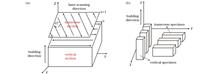
ObjectiveSelective laser melting (SLM) is a commonly used technology for the additive manufacturing (AM) of metal material. It uses a high-energy laser beam to melt the metal powder layer-by-layer and finally prints the desired parts. During the SLM process, the printed part on the top plane (the XOY plane in Fig. 2 in the vertical printing direction) and the printed part on the side plane (the YOZ plane in Fig. 2 in the parallel printing direction) have different heating histories and temperature gradients. Therefore, the two planes have significantly different microstructures. This anisotropy in the microstructure is bound to introduce anisotropy to the performance. Recently, several studies have been conducted on the effect of microstructural anisotropy on mechanical properties. The unified conclusion is that printed samples have better mechanical properties in the vertical printing direction than in the parallel printing direction. However, few studies have been conducted on the effect of microstructural anisotropy on the corrosion behavior of printed parts, and their conclusions are different. Therefore, it is necessary to further investigate this issue. The aim of this study is to investigate the corrosion behaviors in different directions (the XOY and YOZ planes) in 316L stainless steel (SS) prepared using SLM through electrochemical measurements and propose internal causes of these corrosion behaviors, which have not yet been described.MethodsThe 316L SS parts are first prepared using SLM. To obtain samples in different directions, including the XOY and YOZ planes, samples are cut according to the diagram shown in Fig. 3. In this study, the forged 316L SS is used as the counterpart after solution treatment. The body and surface density of 316L SS are measured using the Archimedes drainage and metallographic methods, respectively. The microstructures of the SLMed sample on XOY and YOZ planes are characterized by electron backscattered diffraction (EBSD) and a scanning electron microscope (SEM). The phase structures of all samples are measured by X-ray diffractometry (XRD). The corrosion behaviors are explored by measuring the open-circuit potential (OCP), potentiodynamic polarization, and electrochemical impedance spectroscopy (EIS). In addition, the internal causes of this effect can be explained by the potentiostatic polarization and characterization of the surface topographies of all parts after corrosion.Results and DiscussionsThe results show that the body density of 316L SS prepared using SLM is 99.38%, which is close to that of its forged counterpart (99.7%). The surface densities of the SLMed sample on XOY and YOZ planes are 99.7% and 99.87%, respectively, indicating that the surface densities in the different directions are almost similar. The XRD results confirm that the additive manufacturing technology does not change the phase structure of the 316L SS (Fig. 5). However, a clear discrepancy is evident in the grain orientation for both planes from the EBSD tests (Fig. 7). On the XOY plane, more (101)-oriented grains are observed, whereas on the YOZ plane, more (111)-oriented grains are observed. According to the literature [26], (111)-oriented grains are more resistant to corrosion. The grain sizes in both planes differ slightly according to the EBSD test results (Fig. 8). The average grain size of the SLMed sample on the YOZ plane (9.51 μm) is slightly larger than that of the SLMed sample on the XOY plane (7.35 μm). However, the grain sizes of SLMed sample on XOY and YOZ planes are significantly smaller than that of the forged counterpart (50-100 μm). The results from the electrochemical tests show that the corrosion resistance of the SLMed sample on the XOY plane is better than that of the SLMed sample on the YOZ plane, and the SLMed sample on both planes are superior to the forged counterpart, as confirmed by the OCP measurements (Fig. 9), potentiodynamic polarization curves (Fig. 10), and EIS measurements (Fig. 11). The improved corrosion resistance of the SLMed sample on the XOY plane is attributed to the fewer (111)-oriented grains on the XOY plane, and consequently, to the more compact passive film formed on the XOY plane based on the results of potentiostatic polarization measurements (Fig. 12). These conclusions are further confirmed by observing the SEM morphologies of the three corroded samples. The sizes of the inclusions on the XOY and YOZ planes of the printed samples are much smaller than those of the forged part (Fig. 13). In addition, the inclusion on the XOY plane remains closely combined with the matrix after corrosion, demonstrating outstanding corrosion resistance. However, for both the SLMed sample on the YOZ plane and its forged counterpart, the case worsens. A clear corrosion gap is present around the inclusions after corrosion, particularly for the forged counterpart, indicating poorer corrosion resistance.ConclusionsFirst, compact 316L SS samples are produced using SLM. Their densities are 99.38%, which are considerably close to that of the forged parts (99.7%). There is a notable difference in the microstructure between the XOY and YOZ planes in the printed part. On the XOY plane, more (101)-oriented grains are observed. However, on the YOZ plane, more (111)-oriented grains are observed. This microstructural anisotropy has a significant effect on the corrosion behavior of 316L SS printed using SLM. The corrosion resistance of the SLMed sample on the XOY plane is better than that on the YOZ plane, and the SLMed samples on both planes are superior to their forged counterparts. The better corrosion resistance of the SLMed sample on the XOY plane results from fewer (111)-oriented grains, leading to more compact passive films formed on the surface. The SEM morphologies of inclusions in the three corroded samples show that the size of the inclusions on the XOY plane is smaller than that on the YOZ plane and that of forged counterpart. In addition, the corrosion gap between the inclusion and matrix on the XOY plane is far less than that on the YOZ plane and that of forged counterpart, indicating better corrosion resistance.
Feb. 25, 2023Vol. 50 Issue 4 0402012 (2023)
Luzhong Zhang, Xiaonan Wang, Xiaming Chen, Wengang Chen, Xiang Li, and Hiromi Nagaumi
Results and Discussions The macro morphology of the welded joint (Fig. 3) indicates that a full penetration weld is obtained when the laser power is higher than 3.6 kW. Statistical analysis results of the welded joint indicates that as the laser power increases, the upper and root melting widths of the weld increase from 3.6 mm to 4.0 mm and 2.0 mm to 2.5 mm, respectively, while the reinforcement height decreases slightly (Fig. 4). The central area of the weld possesses the typical as-cast structure, containing several equiaxed grains and little porosity (Fig. 5). When the heat input increases, the cooling rate decreases, which leads to a decrease in subcooling and promotes the growth of columnar crystals. The average width of the columnar crystal band near the bond line is 134 μm, 152 μm, and 232 μm when the laser power is 3.6 kW, 4.2 kW, and 4.8 kW, respectively (Fig. 6). The microhardness distribution patterns of the three welded joints are similar, with the weld and heat affected zone (HAZ) hardnesses being significantly lower than those for the base material (~130 HV). The average hardnesses of the weld and HAZ show a decreasing trend with increasing laser power (Fig. 7). The lower weld hardness and porosity weaken the joint, which eventually leads to the fracture of the welded joint at the seam. The joint tensile strength is the highest (271 MPa) when the laser power is 3.6 kW, while the joint tensile strengths are 244 MPa and 220 MPa for laser powers of 4.2 kW and 4.8 kW, respectively. The highest weld tensile strength occurs at low laser powers, with the joint possessing the tensile strength of approximately 64% of that of the base material at the power of 3.6 kW (Fig. 8).ObjectivesAs a heat-treatable high-strength aluminum alloy with low density, good mechanical properties, easy forming, and corrosion resistance, Al-Mg-Si alloys have been widely used in high-speed railroads, automobiles, aerospace, and other fields. The addition of Cu to Al-Mg-Si alloys is more economical and applicable. It improves the mechanical properties and age-hardening efficiency at peak aging, resulting in ultimate tensile strength of 400 MPa at peak aging for high-strength Al-Mg-Si-Cu alloys, which is significantly higher than that of existing commercial Al-Mg-Si alloys. Softening the heat-affected zone during welding is a major problem that limits the use of heat-treatable aluminum alloys. Laser-CMT composite welding (CMT, cold metal transfer) is a promising high-performance, low-welding distortion technology that utilizes the advantages of laser and CMT welding to overcome the shortcomings of both single-laser and traditional arc welding, while increasing productivity and improving welding quality. Therefore, this study investigates the effects of laser power on the macroscopic morphology and tissue properties of the welded joints of high-strength Al-Mg-Si-Cu alloys and evaluates the possibility of applying laser-CMT composite welding technology to high-strength Al-Mg-Si-Cu alloys.MethodsIn this study, a high strength Al-Mg-Si-Cu alloy with a thickness of 2 mm and filler wire with a diameter of 1.2 mm were used. A 6-kW laser and arc welding machine were used for butt-welding laser-CMT hybrid welding experiments. The welding parameters were as follows: laser powers of 3.0, 3.6, 4.2, and 4.8 kW; wire-feeding speed of 4 m/min; welding speed of 4 m/min; laser beam diameter of 0.3 mm, and the distance of 3 mm between the laser beam and arc . The specimens were then etched using the Keller reagent (1 mL HF, 1.5 mL HCl, 2.5 mL HNO3, and 95 mL H2O). The microstructures of the fusion zone and bead dimensions for every welding condition were examined using an optical microscope (OM). The weld microstructure was analyzed using scanning electron microscopy (SEM) after polishing and without a chemical etchant. The Vickers microhardness was measured along the joint cross-section. Dogbone-shaped samples for tensile testing were cut from the weldment perpendicular to the weld fusion line. A tensile strength test of the hybrid joint was performed at room temperature on a tensile machine.ConclusionsLaser-CMT composite welding is developed to combine high strength Al-Mg-Si-Cu alloys. The characteristics of the welded joint are altered by changing the laser power. Full penetration joints are obtained when the laser power is higher than 3.6 kW. The weld width increases and the reinforcement height decreases slightly with increasing laser power. The weld consists of columnar and equiaxed crystals, and the columnar zone of the weld widens with increasing laser power (from 134 μm at 3.6 kW to 232 μm at 4.8 kW). Increasing the laser power also increases the weld dilution and Mg burnout; this decreases the Si and Mg concentrations in the weld, reducing their solid solution strengthening effects. Consequently, the weld hardness and strength decrease with increasing laser power. Overall, the best mechanical properties of the welded joint are obtained at a laser power of 3.6 kW, with the average hardness and tensile strength of the weld reaching 65% (85 HV) and 64% (271 MPa), respectively, of the base material.
Feb. 25, 2023Vol. 50 Issue 4 0402013 (2023)
Jiayu Liang, Wenyang Zhang, Wei Liu, and Bingqing Chen
Results and Discussions The size of the three heat exchange cores with different materials reaches 150 mm×150 mm, the heat exchange efficiencies are all greater than 1000 m2/m3 (Table 3), the dimensional accuracy is controlled within ±0.1 mm, and the surface roughness is less than 10 μm (Tables 5, 6, and 7). Compared with the traditional plate-fin heat exchanger with a heat exchange efficiency of 875 m2/m3, which has the same size as that of the heat exchange core, the volume and weight of the lattice heat exchange structure decrease by 24.9% and 66.6%, respectively (Table 4), and the heat exchange efficiency increase by 10%. However, because single cells used have the same size, the simulated heat exchange efficiencies of the three material lattice structures are the same, but the values measured by micro-nano CT 3D imaging are different. This study demonstrates that the simulated value, compared with the measured heat exchange efficiency of the TC4 alloy lattice structure heat exchanger, has the smallest deviation. The deviation between the simulated and actual heat exchange efficiency values is primarily caused by the difference between the actual value and digital model obtained by printing. Currently, TC4 alloy is the most mature material in laser-selective melting formation, and it has good adaptability to laser-selective melting formation; therefore, the component obtained by printing is closer to the digital model. For the B30 copper alloy, owing to the high reflectivity of the laser, high thermal conductivity, and other factors, the difference between its laser-manufacturing components and mathematical models is significant. The 316L alloy case is intermediate between those of the TC4 and copper alloys.ObjectiveTraditional radiators have a large volume, heavy weight, and low dissipation efficiency. Using the laser-additive manufacturing technology, the volume and weight of the heat sink with lattice structure significantly reduce under the same heat dissipation efficiency of the traditional radiator . Therefore, laser-additive manufacturing of heat sinks with lattice structures is a promising technology. In this study, three types of radiators with lattice structures are fabricated using laser-additive manufacturing technology with 316L, TC4, and B30 powder materials and compared with traditional radiators.MethodsBased on the confirmation of the powder characteristics, the laser-forming process parameters of the 316L stainless steel, TC4 titanium alloy, and B30 copper alloy are investigated. Alloy specimens with different metallographic parameters are formed, and their internal metallurgical properties are analyzed. Process parameters with good forming quality are selected as optimized technological parameters. Previous studies have shown that the Kagome lattice has a good heat dissipation effect, and the central vertex of the Kagome lattice acts as a vortex generator, which disrupts the basic flow and causes stillness and separation of media . The complex flow behavior simultaneously strengthens the conduction of the wall and connecting rod. In this study, the size of the Kagome lattice is optimized for laser manufacturing. Using laser selective melting, lattice-structured heat exchangers are fabricated with 316L stainless steel, TC4, and Cu alloys. A three-dimensional image of the lattice structure is reconstructed using computed tomography (CT), the heat exchange area value of the structure is also calculated, the core body size and the surface roughness of the laser-selective manufactured lattice structure are measured, and a self-made device is used to evaluate the heat transfer performance of the heat exchanger.ConclusionsIn this study, based on the Kagome lattice, the size suitable of lattice cell structure for additive manufacturing heat exchangers is optimized. Compared to the traditional plate-fin heat exchange structure with a heat exchange efficiency of 875 m2/m3, the volume and weight of lattice structure decrease by 24.9% and 66.6%, respectively, when the heat exchange efficiency is increased by 10%. The lattice-structured heat exchanger cores with 316L stainless steel, TC4 titanium alloy, and copper alloy are prepared by laser-powder selective melting. The size of the heat exchange core reaches 150 mm×150 mm, and the heat exchange efficiency is greater than 1000 m2/m3. The dimensional accuracy is controlled within ±0.1 mm, and the surface roughness is less than 10 μm. The lattice-structured heat exchanger achieves high performance and precision for all three different materials. The evaluation formula of the heat exchange efficiency should comprehensively consider the influence of physical parameters and other factors to improve further.
Feb. 25, 2023Vol. 50 Issue 4 0402014 (2023)
Xiuquan Ma, Libo Wang, Zhengwu Zhu, Chunming Wang, and Gaoyang Mi
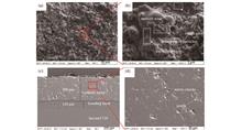
ObjectiveOwing to the excellent strength, plasticity, and corrosion resistance, 316L stainless steel is widely used in nuclear and chemical industries. The efficient cutting of thick plates is realized using lasers, which are high-energy-density heat sources. During the laser cutting process, the plate material melts and is blown off vertically under the action of a coaxial compressed gas. Therefore, a kerf is formed. During a rapid thermal cycle, an extremely thin recast layer (the order of microns) is formed on the surface of the kerf. During the solidification of the recast layer, a particular temperature gradient and fluid motion significantly influence the morphology and the texture of the structure at room temperature. In previous studies, researchers have mainly focused on the influence of parameters, such as laser power, cutting speed, and pressure of compressed gas, on the cut formation and its quality. Few studies have focused on the microstructural morphology and formation mechanism of the recast layer. The differences between the as-solidified microstructure and the substrate may lead to non-negligible changes in the properties of the edge, which in turn affects the overall characteristics. To study the morphology and microstructural growth of the recast layer, an 18 mm thick 316L austenitic stainless steel plate is taken as the object of laser cutting for this study. The solidification mechanism of the recast layer at different kerf sites during the laser cutting process is revealed.MethodsAn 18 mm thick 316L austenitic stainless steel plate was employed as the base metal for this study. A pulsed laser was used to cut the base metal to form a kerf. N2 was chosen as the compressed gas, and its flow direction was coaxial with the laser. Representative specimens were then sampled to analyze their surfaces. Transverse and surficial microstructural morphologies of the recast layer, under the laser action, were analyzed using scanning electron microscopy and electron back scattering diffraction (EBSD). In addition, the recast surfaces were cleaned using anhydrous ethanol. The transverse surfaces were treated using coarse grinding, fine grinding, and polishing techniques. The polished surface was then etched with diluted aqua regia (volume ratio of HCl, HNO3 and H2O is 3∶1∶4).Results and DiscussionsThe distribution of the main elements on the surface of the recast layer is analyzed using energy dispersive spectroscopy. The results indicate that no significant element change occurred along the thickness, except for a slight loss of Fe (Table 5). The grain growth mode of the recast layer is further analyzed using EBSD at the 1/3 site from kerf top and the kerf bottom site . The results indicate that epitaxial growth is the primary growth mode. However, the proportion of non-epitaxial growth at the 1/3 site from kerf top (Fig. 5) is observed to be higher than that at the bottom site (Fig. 7). A comparison between the IPF orientation distribution and pole figures in Figs. 9 and 10 also shows that the grain growth at the 1/3 site from kerf top exhibits some fluctuations with unmixed and unperturbed features.ConclusionsThe results show that a small amount of Fe evaporates from the recast layer surface. A variation in flow state from turbulent at the top to laminar at the bottom surface is observed, with an increase in thickness and needle-like grains. For crystal orientation, the ratio of the epitaxial growth at the top surface of the recast layer is lower than that at the bottom surface. Such a random distribution of epitaxial growth is caused by the turbulent flow at the former, whereas the dominant epitaxial growth is induced by the laminar flow at the latter. Considering the grain profiles, the γ phase in the base metal is equiaxed, whereas the δ phase is arranged in a banded form. The morphology of the γ phase grains in the recast layer is irregular and coarsen by approximately 2 times compared to those of the base metal. However, the δ phase is dispersed and refined from 1/6 to 1/2 of the base metal. Under the conditions of an extremely high-temperature gradient and a disordered disturbance owing to melting, a substantially reduced duration of δ phase formation with considerable dispersion is produced.
Feb. 25, 2023Vol. 50 Issue 4 0402015 (2023)
Wenfeng Yang, Dehui Lin, Mian Zhong, Shaolong Li, Ziran Qian, Guochun Liu, Yu Cao, Yi Xu, Guo Li, and Sai Zhang
ObjectiveUnderstanding the crater morphology on the surface of a paint layer after a single laser pulse can effectively suppress the superposition effects of multiple laser parameters and the photothermal and photomechanical effects of a pulse overlap. This helps reveal the laser-material interaction mechanism and provides a basis for the optimization of laser parameters. In recent years, many scholars have simulated the morphology of craters on the surface of a paint layer with the help of finite element software after nanosecond pulsed laser action based on the ablation mechanism. The laser parameters are then optimized based on the simulation results. For nanosecond pulsed lasers, the main mechanism of the laser-material interaction varies at different energy densities (the main mechanism is the ablation mechanism at low energy density, and the plasma shock and thermal radiation mechanism at high energy density). The ablation mechanism, plasma shock, and thermal radiation mechanism have different effects on the morphology of the crater. This study aims to establish a model of the damage form and the removal process of the paint layer during a single pulse of a nanosecond laser under different energy densities, to reveal the differences in the influence of the laser-material mechanism on the morphology of craters under different energy densities, and to provide a reference for the precise control and parameter optimization of the paint removal effect at high and low energy densities.MethodsA nanosecond pulsed laser with a wavelength of 1064 nm and beam energy following a Gaussian distribution was applied to the epoxy primer surface. The diameter, depth, and three-dimensional morphology data of the craters on the surface of the paint layer were measured using a 3D optical surface profiler after the laser pulse. A simulation model of crater morphology was established based on the ablation mechanism and the fitting relationship between the depth (d) of the craters and energy densities (F). MATLAB was used to simulate the morphology of the craters in the energy density range of 13.58-27.16 J/cm2, and an experimental verification was carried out. Error analysis of the experimental and simulation results under a high density revealed the influence of the plasma shock and thermal radiation mechanism on the morphology of the crater. The model correction and experimental verification were carried out based on the plasma shock and thermal radiation mechanisms.Results and DiscussionsThe simulation model of crater morphology based on the ablation mechanism has an error of less than 5% for crater depth and diameter at a low energy density (13.58-16.98 J/cm2), less than 5% for crater depth error at a high energy density (20.37-27.16 J/cm2), and up to 40% for diameter error (Fig.5). The error analysis shows that at a high energy density, the plasma shock and thermal radiation mechanisms are the main reason for the diameter error (Fig.7). After the model was corrected based on the above analysis, the diameter and depth errors of the craters under a high energy density were controlled within 5%, which significantly improved the accuracy of the model (Fig.9). The model shows that at a low energy density, the surface of the crater is approximately rotated paraboloid, and the profile of the crater is similar to a parabola; at a high energy density, the surface of the crater can be regarded as a combination of multiple normally-distributed surfaces, and the crater profile as a combination of multiple normal distribution curves.ConclusionsAt different energy densities, differences in the laser-material mechanism are noted; the ablation mechanism at a low energy density and the laser plasma shock and thermal radiation mechanisms at a high energy density are the main interaction mechanisms. Differences in the laser-material interaction mechanisms cause damage to the paint layer. Compared to the ablation mechanism, the plasma shock and thermal radiation mechanisms lead to an increase in the amount of paint removed near the surface of the crater and a wider profile near the crater surface. A simulation model of crater morphology is established for different laser-material mechanisms, thereby effectively improving the model accuracy. The study results provide a reference for the accurate control of the laser paint removal process and the optimization of paint removal parameters under high and low energy densities.
Feb. 25, 2023Vol. 50 Issue 4 0402016 (2023)
Jikang Fu, Hongjun Liu, Jibin Zhao, Yuhui Zhao, Chen He, and Zhiguo Wang
ObjectiveAiming at the dense porosity defects detected using X-ray in laser melting deposition connected AlSi10Mg alloy, which is manufactured using selective laser melting, the characteristics of the defect and its influence on the mechanical properties are analyzed, and the elimination method of the defect is also explored. Selective laser melting methods cannot prepare large-scale aerospace structural components, laser melting deposition overcomes the forming size limitations, and provides a feasible solution for the additive manufacturing of large structural components.MethodsIn this study, the AlSi10Mg alloy prepared using selective laser melting was used as the base, and a laser melting deposition connection experiment was performed. First, connection samples under different laser powers were prepared. The relationship between the distribution range of dense porosity defects and the laser power was analyzed by an X-ray inspection, and the effect of dense porosity on the microhardness of the connection region was measured. The dense porosity was observed and analyzed using scanning electron microscopy (SEM) to determine its type and formation mechanism. Then, a substrate preheating experiment was performed to explore the best preheating temperature, which is used to solve the dense porosity defects in the connection region. Finally, the microhardness and tensile properties of the connection region before and after preheating were tested, and the fracture morphology was analyzed.Results and DiscussionsThe inspection of the prepared connection samples with different energy densities shows that the dense porosity primarily appeared at the position of the interface fusion line between the connection region and substrate, and the dense porosity decreases the microhardness of the bonding zone (Fig. 7). Using SEM to observe the dense porosity, it is discovered that the porosity is primarily hydrogen porosity (Fig. 9). The solubility of hydrogen in molten pool decreases fastly, causing most bubbles to escape and form bubbles. However, the bubbles rise slowly, giving numerous bubbles no time to escape. So, some dense porosity defects are formed in this position. The preheating experiment shows that the optimum preheating temperature is higher than 100 ℃, which can effectively solve the dense porosity defects. The hardness at the fusion line reaches 90.8 HV after preheating (Fig. 14); the tensile strength is 287 MPa, and the elongation is 5.0% (Fig. 15). The observation of the fracture morphology shows that the fracture types before and after preheating are all brittle fractures and numerous dimples and quasi-cleavage morphologies can be observed on the fracture surface (Fig. 17).ConclusionsDense porosity is the primary defect of the AlSi10Mg alloy, which is produced using laser melting deposition. The defect is located at the position of the interface fusion line between the connection region and substrate, which is characterized as a watermark phenomenon on the X-ray inspection film. The accumulation of dense porosity results in a much lower hardness at the fusion line than in the connection zone and substrate. Preheating can effectively change the agglomeration effect of the dense porosity, making them evenly dispersed from the fusion line to the connection region. The mechanical properties of the samples after preheating were significantly improved. The hardness at the fusion line increased by 45% compared with that without preheating. The tensile strength increased by 19%, and the elongation increased to 5.0%.
Feb. 25, 2023Vol. 50 Issue 4 0402017 (2023)
Wei Wang, Xiangcheng Ji, Weijun Liu, Fei Xing, and Hongyou Bian
Objective5083 aluminum alloy is widely used in aircraft plate weldments and fuel tanks. The presence of anodized film on this alloy strongly impacts the welding quality, making a high-quality removal technique essential. Compared with traditional cleaning methods, laser cleaning characteristically achieves high positional accuracy, strong cohesion, good stability, and low damage. It also avoids generating unwanted residue that changes the surface appearance and roughness of the aluminum alloy, seriously affecting the follow-up welding, coating, and other processes. Differences in the surface appearance of aluminum alloys before and after laser cleaning have been widely studied but without a systematic explanation of the underlying reasons for changes in surface appearance and roughness. This study aims to explore the influence of laser-processing parameters on the cleaning surface appearance, surface roughness, elementary composition, and content changes, as well as to establish a laser cleaning process window for a 5083 aluminum alloy anodized film. Using optimized process parameters, the resulting improved cleaning can provide technical support for follow-up processing techniques.MethodsThis study uses a 5083 aluminum alloy plate coated with anodized film. First, the anodized film on the alloy surface is cleaned using a pulse fiber laser with different single-pulse energies, impulse frequencies, and spot travel speeds. The changes in the alloy surface morphology and roughness after cleaning are observed using the optical microscopy, laser confocal microscopy, and scanning electron microscopy. The composition and content of the elements on the sample surface are detected using an energy spectrum analyzer equipped with a scanning electron microscope. Finally, the mechanism of the removal of the anodized film on the alloy surface, achieved via laser cleaning, is analyzed.Results and DiscussionsFirst, it is concluded that the cleaning effect is optimized for single-pulse energy of 100 mJ and an impulse frequency of 9.67 kHz after analyzing the influence of single-pulse energy and impulse frequency on the cleaning effect. Second, under these conditions, the influence of the laser-spot travel speed on the optimization of the cleaning effect is studied. When the laser spot travels at 12.5 mm/s, the overlap rate of the light spot along the laser cleaning direction is large [Formula (5)], the residence time of the light spot on the oxide film per unit area is short, and large oxide film remains on the surface [Figs. 10(f) and 12(f)]. As the laser spot travel speed slows down to 6.5 mm/s, the overlap rate of the light spot increases, the surface after removing the oxide film is smooth and flat [Figs. 10(c) and 12(c)], the minimum roughness of the surface is Sa=0.608 μm (Fig. 13), the oxygen content(mass fraction) decreases to a minimum of 3.46%, and the aluminum content(mass fraction) increases to a maximum of 79.98% (Figs. 19 and 20). When the laser spot moves slowly, the matrix surface is burned and the piezoglypt is formed [Fig. 19(b)]. When it moves even more slowly, the bulged overlapping appearance at the edge of the piezoglypt becomes unstable and the wave-like appearance forms [Fig. 19(a)]. The removal mechanism of oxide film depends on the laser energy and mainly includes thermal ablation and hole blasting assisted by elastic vibration peeling [Figs. 15(a), 15(c), 17(i), 18, and 23 and Table 4].ConclusionsIn this study, the effects of the laser-cleaning process parameters on the surface appearance, roughness, elementary composition, and content of 5083 aluminum alloy after removing anodized film are studied. The pulse frequency affects the light-spot overlapping rate in the scanning-galvanometer direction, and the laser-spot travel speed affects its overlapping rate in the cleaning direction. We conclude that a high impulse frequency or a low laser-spot travel speed produces secondary oxidation. With increasing the single-pulse energy, the surface roughness first increases and then decreases, with a minimum value Sa=0.668 μm. With increasing the impulse frequency, the surface roughness decreases and then increases twice, with a minimum value Sa=0.660 μm. As the laser-spot travel speed increases, the surface roughness first increases, then decreases, and finally increases. The minimum roughness is Sa=0.608 μm. For single-pulse energy E=100 mJ, pulse frequency F=9.67 kHz, scanning galvanometer speed Vx=4000 mm/s, and laser-spot speed Vy=6.5 mm/s, the cleaning rate of the oxide film reaches 97.14%, and the surface roughness is Sa=0.608 μm. The roughness is lower than that of the mechanically polished oxide film Sa=1.180 μm. The laser removal mechanism of the anodized film of the 5083 aluminum alloy mainly involves thermal ablation and hole blasting assisted by elastic vibration peeling.
Feb. 25, 2023Vol. 50 Issue 4 0402018 (2023)
Ronggui Lu, Xinyue Zhang, Xu Cheng, Jia Li, Dong Liu, Yudai Wang, and Yiwei Liu
ObjectiveNickel-based superalloys are typically used as turbine disks and turbine blade materials in aeroengines owing to their excellent high-temperature performance. Because of the different service conditions of the turbine disk and turbine blade, the premature failure of joints can be avoided using gradient materials. However, a change in the composition of the gradient transition zone can change the microstructure, which significantly affects the properties of the alloy. Therefore, the evolution of the microstructure and the hardness of laser melted nickel based superalloys must be investigated, providing a basis for the laser additive manufacturing of gradient nickel-based superalloys.MethodsThe materials used in this experiment are IC10 directional superalloy and FGH9X powder superalloy with a particle size of 0.15-0.25 mm. IC10 and FGH9X powders are prepared as nickel-based superalloy powders with different compositions, and alloy ingots with 11 typical gradient components are prepared by changing the ratio of the two alloys. (From samples F100 to F0, the mass fraction of FGH9X decreases by 10% intervals, and the mass fraction of IC10 increases by 10% intervals. For example, the FGH9X mass fraction of the F80 sample is 80% and the IC10 mass fraction is 20%). A 50 g nickel-based superalloy mixed powder is prepared and placed in a copper crucible. The laser power and opening time are set to 5 kW and 2 s, respectively. A melting experiment is performed in an argon atmosphere, and the alloy ingot samples are obtained after air cooling. The microstructures of the samples are observed using an optical microscope (Leica DM4M) and scanning electron microscope (Apreo S LoVac). The primary dendrite spacing, γ' phase size, and γ' phase content are measured using the Image Pro Plus software. Thermo-Calc 2020b is used to simulate the nucleation driving force of the γ' phase in the alloys. A hardness test is performed using a micro Vickers hardness tester (MH-6) with a load of 4.9 N and a holding time of 15 s.Results and DiscussionsThe microstructure of the 11 nickel based alloy samples prepared via laser melting is composed of dendrites, and primary and secondary dendrites. When the sample changes from F100 to F0, the dendrite morphology of the alloys remains almost unchanged, and the primary dendrite spacing is in the range of 100-120 μm. Based on literature review, the dendrite morphology and dendrite spacing of the alloys are primarily affected by the cooling conditions, and the effect of alloy composition is insignificant. An analysis of the alloy microstructure shows that the 11 types of nickel-based alloys are composed of the γ and γ′ phase, carbides, and the γ/γ′ eutectic phase (Fig. 3). When the alloy composition changes from F100 to F0, the content and size of the γ′ phase increase continuously (Fig. 5), which is due to the gradual increase in Al and Ta contents in the alloys. The nucleation driving force of the γ' phase increases and more γ' phases precipitate. In addition, owing to element segregation, the content and size of the interdendritic γ' phase differ significantly from those of the dendritic trunk γ' phase. The content of γ' phase in interdendritic zone is more than that in dendritic trunk and the size of γ' phase in interdendritic zone is larger than that in dendritic trunk. In addition, the results show that the change in alloy composition does not significantly affect the microhardness, and that the overall hardness value is approximately 500 HV. This is because as the alloy composition changes from F100 to F0, the content of solid-solution strengthening elements and the content of carbides with high hardness and brittleness in the alloys decrease gradually, whereas the hardness and size of the γ' phase increase gradually; therefore, the hardness of the 11 types of nickel-based alloys is similar.ConclusionsPrimary dendrite and secondary dendrite arms are developed in the microstructures of the 11 types of nickel-based superalloy ingots prepared via laser rapid melting. The change in alloy composition does not significantly affect the dendrite morphology, and the average primary dendrite spacing is 110 μm. The microstructures of the alloys are composed of the γ phase, γ′ phase, carbides, and the γ/γ′ eutectic phase. As the powder nickel-based alloy content in alloy ingots decreases, the content and size of the γ 'phases increase continuously. As a result of element segregation, Al, Ti, Ta and Nb, which are the constituent elements of the γ 'phase, segregate in the interdendritic regions, thus causing the content and size of the γ' phase in the interdendritic regions are greater than those in the dendritic trunk. The microhardness values of the 11 samples are similar, and the overall hardness value is approximately 500 HV.
Feb. 25, 2023Vol. 50 Issue 4 0402019 (2023)
Dasong Liao, Qian Wang, Feisen Wang, Hui Chen, Fei Ji, Ting Wen, and Lei Zhou
Results and Discussions As the pulsed laser scanning speed is increased, the surface oxide film and oil stain are gradually removed, and the original dark-gray surface of the TC4 titanium alloy becomes golden-yellow, then light-yellow, and finally silvery-white (Fig. 2). The microscopic morphology of the TC4 surface changes with increasing scanning speed. When the scanning speed is low, ridge structures and cracks form on the surface, along with severe thermal oxidation. The surface becomes smoother and the thermal oxidation decreases with increasing scanning speed, but the effect of removing the oxide film is reduced at a large scanning speed (Fig. 3). The scanning speed affects the number of pulses in the unit spot area, the cumulative input energy, and the overlap rate of the spot; therefore, pulsed laser at different scanning speeds produces different surface morphologies of the titanium alloy substrate (Fig. 4). With an increase in scanning speed, the O content on the TC4 surface first increases then decreases, and then increases, while the Ti content shows the opposite trend. The main component of the oxide film on the TC4 surface is TiO2. When the scanning speed is 500 mm/s, TiO forms on the surface by thermal oxidation. When the scanning speed is increased to 9000 mm/s, the surface oxygen content is the lowest, the substrate material is exposed, and the cleaning quality is the best (Figs. 5, 6, and 7). The roughness of the TC4 surface first increases and then decreases with increasing scanning speed, which is closely related to the changes in surface morphology (Fig. 8). Due to the formation of a remelted layer with grain refinement and acicular martensite α′ and laser shock strengthening effect on the surface, the hardness of the TC4 surface increases after laser cleaning, and then gradually decreases with increasing scanning speed (Figs. 9 and 10). Compared to the original, the laser-cleaned TC4 surface has increased corrosion resistance due to the remelted layer, reduced roughness, and the formation of a dense oxide film by slight oxidation (Figs.11 and 12).ObjectiveTC4 titanium alloys have excellent overall performance and are widely used in the manufacture of key components for aerospace and military hardware. However, the oxide film on the surface can adversely affect its formation and performance, which results in porosity in the weld, reduced mechanical properties, reduced electrical conductivity, and weakened bonding of the plating or coating with the substrate. Therefore, the oxide film must be removed from the titanium alloy. Traditional methods for cleaning the oxide film on the surface of titanium alloys have many limitations. However, laser cleaning technology compensates for the shortcomings of traditional cleaning approaches with features such as being green, being efficient, and causing low damage. Several studies have discussed the influence of laser energy density on the cleaning effect. In this study, the effects of scanning speed on the cleaning effect of the oxide film on TC4 titanium alloy surfaces are studied. The results can help optimize the laser cleaning process and improve the cleaning quality and efficiency of titanium alloys.MethodsIn this study, a nanosecond pulsed fiber laser is used to remove oxide film and oil stain from a TC4 titanium alloy surface at different scanning speeds. The surface morphology of the cleaned TC4 titanium alloy is observed by scanning electron microscopy (SEM). The effect of different scanning speeds on the surface chemical composition and chemical bonds of the sample surface is analyzed by energy-dispersive spectroscopy (EDS), X-ray diffraction (XRD), and X-ray photoelectron spectroscopy (XPS). The surface roughness is measured using a laser confocal microscope and the hardness of the surface is measured using a Vickers hardness tester with a load of 200 g. Finally, the corrosion resistances of TC4 titanium alloy before and after laser cleaning are measured on an electrochemical workstation.ConclusionsThe scanning speed has a significant effect on the cleaning of oxide film and oil stain on the surface of TC4 titanium alloy. When the scanning speed is 500 mm/s, the surface becomes golden-yellow due to thermal oxidation, and significant remelting and cracking occur. The O content (mass fraction) reaches 24.86%, and the oxide TiO forms. With an increase in scanning speed from 3000 mm/s to 9000 mm/s, the original dark-gray surface of TC4 becomes silvery-white, and the amount of thermal oxidation is gradually reduced. When the scanning speed is 9000 mm/s, the O content(mass fraction) reaches its lowest value of 4.54%, and the Ti content (mass fraction) reaches its highest value of 84.2%. The oxide film and oil stain are removed, and the substrate material is exposed. The surface roughness of TC4 titanium alloy gradually decreases with increasing scanning speed. Laser cleaning technology can improve the hardness and corrosion resistance of a TC4 surface, and the enhancement effect is affected by the scanning speed.
Feb. 25, 2023Vol. 50 Issue 4 0402020 (2023)
Daoqi Li, Tao Wang, Zifan Yang, Yubin Li, and Shuwen Wang
Results and Discussion Laser polishing with the optimal combination of process parameters reduces the surface roughness of 304 stainless steel by approximately 67%. After laser polishing, the mass fraction of C and Cr in the polished layer decreases by 2.4% and 3.2%, respectively [Figs. 8(b), 8(d), 9(b), and 9(d)], while the average grain size decreases by 0.37 μm (Fig. 13). The polished surface generates the residual tensile stress of approximately (139.6±68.7) MPa (Table 4). The hardness test reveals that the surface microhardness of 304 stainless steel decreases by approximately 15% (Table 5). This is primarily due to the decrease in the C content, which reduces the amount of carbides on the surface of the material. Electrochemical tests reveal that the corrosion current density increases by 10.978 μA/cm2 after laser polishing (Table 6), primarily because the reduction in the Cr content weakens the passivation ability of stainless steel. Concurrently, grain refinement and residual tensile stress provide a rapid diffusion path for corrosive Cl-.ObjectiveAs a new technology for laser surface treatment, laser polishing has the advantages of being a no-contact and non-polluting approach with high controllability. Laser polishing is accompanied by rapid heating and cooling of the shallow metal layer in the area being polished. Changes in polishing layer performance and their causes must be multifaceted. Few studies have been conducted on the performance changes and mechanisms associated with the pulse laser polishing process. Moreover, the variation trend of element content has not been considered while analyzing the mechanism of polishing layer performance in previous studies. In this study, an orthogonal experiment of laser polishing of AISI304 stainless steel is conducted; the correlation among various process parameters is analyzed, and the optimal combination of process parameters for achieving high polishing performance is determined. In addition, the properties of the surface before and after laser polishing are evaluated, and the mechanism of the properties of the polishing layer is analyzed based on grain size, residual stress, and variations in the element content. We expect that our findings will serve as a reference for improving metal surface quality using laser-polishing technology in future.MethodsIn this study, the laser power, repetition frequency, defocus distance, and scanning speed of the pulse laser are considered as the influencing factors, and surface roughness is used as the evaluation index to design an orthogonal laser polishing experiment. The polishing route has a “bow” shape [Fig. 3(b)], with a 0.03 mm gap between the filling lines. The three-dimensional (3D) morphology of the surface is observed using an optical microscope, and the surface roughness is measured using a probe roughness instrument. The surface microhardness values of the samples are measured using a Vickers hardness tester. In addition, electrochemical polarization tests are conducted in an electrochemical workstation to detect the corrosion resistance before and after laser polishing. The polished layer is subsequently analyzed using scanning electron microscopy, electron backscatter diffraction, X-ray diffraction, and residual stress detection analyses.ConclusionsIn the orthogonal experiment of the pulsed laser polishing of AISI304 stainless steel, the laser power, repetition frequency, defocus distance, and scanning speed are considered as the influencing factors, and the surface roughness is used as the evaluation index. The optimal combination of laser polishing process parameters has been obtained. Before and after laser polishing, the changes and mechanisms of the surface properties have been systematically analyzed. The following conclusions are drawn. 1) According to the range analysis of the orthogonal experimental results, the defocus distance, laser power, repetition frequency, and scanning speed have the highest impact on the laser polishing effect. The optimized combination of process parameters is as follows: the laser power is 12 W; the defocus distance is 2 mm; the repetition frequency is 70 kHz; the scanning speed is 1750 mm/s, the energy density of a single laser spot is 2.82 J/cm2; the overlap rate of the transverse spot is 72%; the overlap rate of the longitudinal spot is 66%; the surface roughness of the sample can be rapidly changed from Ra=0.5724 μm to Ra=0.1903 μm. 2) Following laser polishing, the microhardness of the sample surface decreases by approximately 15%; the self-corrosion current density increases from 2.858 μA/cm2 to 13.836 μA/cm2; the mass fractions of C and Cr in the polished layer decrease by approximately 2.4% and 3.2%, respectively, and the average grain size is refined by approximately 0.37 μm. The polished surface has a residual tensile stress of approximately (139.6±68.7)MPa, and laser polishing enhances the conversion of γ to α. 3) Considering the analysis results, the decrease in the C element content reduces the amount of carbides on the surface of the material, thereby decreasing the surface microhardness of 304 stainless steel. The decrease in the Cr content in the polishing layer causes the newly formed oxide film on the surface of the sample to be less dense than that on the original surface. Simultaneously, the continuous action of residual tensile stress causes cracks in the newly formed oxide film, and grain refinement increases the grain boundaries, providing a rapid diffusion path for corrosive Cl-. Consequently, the corrosion resistance of 304 stainless steel is reduced.
Feb. 25, 2023Vol. 50 Issue 4 0402021 (2023)
Ye Ma, Cheng Lei, Ting Liang, Pengfei Ji, Yuqiao Liu, Bingyan Wang, and Guofeng Chen
Results and Discussions The prepared sapphire through hole diameter is 200 μm, the taper is 2?, the maximum hole edge damage width is 5.74 μm, and there is almost no heavy condensate at the hole edge (Fig. 9). In general, a suitable laser energy density enables the sample to melt and vaporize, which can reduce the splash of the molten material and improve the quality of the through-hole surface (Fig. 4). The higher the repetition frequency of the laser, the longer the corresponding pulse width, and the thermal effect of the laser is enhanced. Owing to the influence of the thermal action, spatter is produced around the processing zone, affecting the roughness of a through-hole surface (Fig. 6). The laser scanning speed directly affects the pulse overlap rate, and an appropriate pulse overlap rate can effectively remove materials and play an important role in reducing the taper of the through hole (Fig. 7).ObjectiveSapphire crystals are commonly used in high temperature pressure sensor chips because of their excellent physical and chemical properties. In particular, in the manufacturing process of an all-sapphire fiber Fabry-Perot cavity high-temperature pressure sensor, the sapphire base must be drilled, and the quality of the through-hole is an important factor to ensure that the fiber can be vertically inserted to realize the effective transmission of optical signals. It is difficult to ensure the quality of sapphire through-holes using traditional mechanical and chemical processing methods. Laser machining technology has non-contact, non-mask, and simple process characteristics, which make it prominent in the field of hard brittle material micro-machining. Recently, there have been reports on the use of ultrashort pulse lasers to punch holes in sapphire; however, its high cost and low processing efficiency make this machining method mainly used in high-precision surface microstructure etching. Short pulse lasers, such as 355 nm ultraviolet nanosecond lasers, are widely used in industrial production owing to their low cost and high efficiency; however, there are few reports on their application in sapphire through hole processing. In this study, we analyze the impact mechanisms of different laser energy densities, repetition frequencies, and scanning speeds on sapphire processing using the control variable method, as well as the parameter space of sapphire through hole processing. We aim to fabricate through holes with diameters of approximately 200 μm and tapering angles of less than 5? on 500 μm thick sapphires without notches, heavy coagulation, or other damages. We hope that our method can provide a new, low-cost, and efficient way to process and cut the internal structure of sapphire.MethodsThis study uses sapphire wafers with a diameter of 5.08 cm and thickness of 500 μm. Before and after the experiment, the sapphire is ultrasonically cleaned with anhydrous ethanol to remove impurities on the surface and avoid effects on the laser processing results. First, using the control variable method, different laser energy densities, repetition frequencies, and scanning speeds are adjusted to drill holes into the sapphire. Subsequently, scanning electron microscopy and laser scanning confocal microscopy are used to analyze the surface morphology and 3D structure of the through-hole under different conditions. The effects of different laser parameters on the surface morphology and taper of the through-hole are studied. Finally, the optimal parameter space to obtain high-quality sapphire through holes is selected based on the experimental results.ConclusionsIn this study, a 355 nm ultraviolet nanosecond laser is used to successfully prepare a through hole on a 500 μm-thick sapphire wafer with a quality identical to or better than that of the ultra-short pulse laser (Table 4). Through the analysis of the drilling results assisted by laser scanning confocal microscopy and scanning electron microscopy, we determine a combination of laser energy density of 31.12 J/cm2, laser frequency of 30 kHz, and laser scanning speed of 0.5 mm/s. The results show that a micro through hole with good surface morphology and small taper can be prepared on the sapphire wafer by adjusting the appropriate combination of laser parameters. The results indicate a certain reference value for processing and cutting sapphire internal structures with a 355 nm all-solid-state ultraviolet nanosecond laser.
Feb. 25, 2023Vol. 50 Issue 4 0402022 (2023)
© Copyright 2018-2021 | Chinese Laser Press.
All Rights Reserved 沪ICP备15018463号-20