


Please enter the answer below before you can view the full text.

Guang Yang, Kaibo Cheng, Shuo Zhao, and Da An
ObjectiveSelective laser melting (SLM) is a metal-additive 3D printing technology based on layer-by-layer printing. It is one of the most promising industrial additive manufacturing technologies for manufacturing metal components. SLM has the advantages of a high degree of freedom and high material utilization; however, the available surface roughness limits the industrial implementation of this technology. Surface roughness refers to the unevenness of the machined part surface with small spacing, small peaks, and valleys: the distance between two peaks or valleys is very small and belongs to the microgeometric shape error. The Ra value of the parts prepared via SLM is usually between 10 and 30 μm; surface roughness is an important indicator of surface quality, and good surface roughness is widely needed to avoid premature failure caused by surface-induced cracks. Poor surface quality not only reduces the strength, wear resistance, and corrosion resistance of the parts, but also affects the accuracy of corresponding processed parts. Excessive surface roughness can directly lead to an inability to meet assembly conditions, usually requiring surface post-treatment, which takes a significant amount of time and operational cost accumulation, reducing the flexibility advantages of SLM. Therefore, optimization of the manufacturing processes and improving the surface quality of metal parts prepared via SLM are crucial.MethodThe main factors that affect surface roughness were identified, their influencing mechanisms were understood, the roughness influencing factors that needed to be modeled were determined, and the step effect, powder adhesion, and warping deformation were comprehensively considered to establish a prediction model. Based on the processing principle of the SLM technology, a mathematical model was established for the step effect of the downward-inclined surface, determining the angle range without support, and improving the traditional roughness prediction model. To understand the influence of powder adhesion and warping deformation on the surface roughness, a schematic of powder adhesion and warping deformation was drawn, and the influence functions of powder adhesion and warping deformation on the surface roughness were calculated. A mathematical expression was further integrated to establish a downward-inclined surface roughness prediction model. The predicted values were compared with measured data, the accuracy of the model was verified, and the errors were analyzed.Results and DiscussionsThe step effect model adopts a method combined with the morphology of the melt channel, replacing the step effect function with the physical quantity of "maximum height difference between peaks and valleys" (Fig. 4). The powder adhesion model adopts an equivalent method to reduce the three-dimensional surface to a two-dimensional surface, and obtains a mathematical model of powder adhesion using the one-dimensional calculation formula for Ra (Fig. 5). The warping deformation is physically represented by the "correction angle" (Fig. 6), which is combined with the step effect model and the powder adhesion model to obtain a mathematical model for predicting the roughness of the entire downward-inclined surface. Comparing the measured data with the predicted data, in the first group, c=11.2 μm was calculated, while the second group of measured data verified the accuracy of the prediction model.ConclusionsThe step effect model optimizes the right-angle edge into a curved edge, calculates the "maximum height difference between the peaks and valleys," and obtains the step effect function. Powder adhesion, as an essential modeling factor, is calculated using the "equivalent transformation" method, which converts 3D to 2D. The metal powder particles that adhered to the surface were equivalent to a rectangular body next to the edge of the step, with a square cross-section of side length c. The uncertainty of side length c was considered to represent different degrees of powder adhesion. The first set of measurement data was used to fit and compare c, and the minimum average error was used as the standard to determine the value of c. The warping deformation was considered as a change in the inclination angle and the overhanging part as a cantilever beam with a constantly changing cross-section. Using the classical Euler-Bernoulli beam theory, the axial and bending deformations of the highest point in the overhanging area were calculated, its shape deviation was predicted, and expressed in the form of a "corrected angle." The comparison analysis between the predicted roughness values of the downward-inclined surface and the roughness measurement data shows that the prediction model can accurately predict the roughness of the downward-inclined surface, and the significant errors generated are due to two reasons: the maximum height difference between peaks and valleys and powder adhesion.
Sep. 25, 2023Vol. 50 Issue 20 2002301 (2023)
Chenghong Duan, Dazhi Shang, Xiangpeng Luo, Hanlin Chi, Xiankun Cao, and Xiaojie Hao
Objective316L stainless steel is widely used in large-pressure equipment parts in the petroleum and chemical industries. Improving the fatigue performance of parts is critical for maximizing the remaining material value. Directed energy deposition (DED) technology has the advantages of high forming flexibility and a short processing cycle, and is considered one of the best choices for pressure equipment remanufacturing. However, defects such as poor surface finish and the generation of tensile residual stresses occur during the DED process. The heat treatment process is typically used to reduce the internal stress of a material to improve its fatigue performance, which is explained in terms of microscopic grain modulation. However, few quantitative studies have been conducted on the residual stress-induced fatigue performance of parts. Therefore, in this study, the finite element method was used to investigate the quantitative influence of residual stress on fatigue crack propagation (FCP) behavior under different heat treatment processes.Methods316L stainless steel was employed in this study. Initially, 3D finite element models of DED and compact tensile (CT) specimens were developed. Subsequently, the effect of different heat treatment processes on the FCP rate of the DED 316L stainless steel parts was investigated by comparing it with conventional 316L stainless steel hot-rolled plates using a combination of experiments and numerical simulations. Based on the virtual crack closure technique, the quantified influence rules of the residual stress on the stress intensity factor (SIF) and effective stress ratio were examined. Finally, the specimen fracture morphology was analyzed using scanning electron microscopy.Results and DiscussionsThe residual stress distribution of DED stainless steel parts was accurately calculated using finite element simulation with an error of approximately 5.05% (Fig.4). The simulated specimen fatigue life matched the experimental results well with an error of approximately 4.71% (Fig.5). The effect of the SIF (Kres) caused by tensile residual stress on the minimum SIF (Kmin) was more significant than that of the maximum SIF (Kmax)(Fig.9). After the heat treatment process, the effective stress ratio of the DED stainless-steel parts decreased from 0.122 to 0.117, which reduced the FCP rate (Fig.10). When the effective stress ratio increased to 0.117 and 0.122, compared to the hot-rolled plate, the FCP rate of DED and heat-treated DED specimens increased by 43.51% and 52.62%, respectively. The FCP rate positively correlated with the effective stress ratio and SIF range, which were fitted using Walker’s formula with good agreement (Fig.11).ConclusionsThe fatigue performance of the conventional 316L stainless steel hot-rolled plate was superior to that of the DED stainless steel parts. The fatigue lives of the DED and heat-treated DED specimens were 63.9% and 69.0% of that of the hot-rolled plate, respectively. The formation of tensile stress zones around the internal dimples of the DED stainless steel parts accelerated crack propagation. After heat treatment, the crack length and the number of cracks at the dimples decreased, which reduced the FCP rate. The SIF (Kres) acts on the FCP rate of DED stainless steel parts by increasing the effective stress ratio (Reff). Based on Walker’s formula, a well-fitted equation correlating the FCP rate, SIF range, and effective stress ratio was obtained. This equation can be used to provide data support for predicting the FCP rate of 316L austenitic stainless steel.
Sep. 25, 2023Vol. 50 Issue 20 2002302 (2023)
Yan Shi, and Dengsong Wei
ObjectivePorosity defects significantly affect the performance of parts manufactured by laser powder bed fusion (LPBF). Reducing or avoiding defects is a key issue in the LPBF technology. The complex, small, and rapid characteristics of the melting and solidification reactions in the LPBF manufacturing process make monitoring and controlling the defects of the formed parts in real-time using existing methods challenging. Traditional trial-and-error methods cannot analyze the formation mechanism of porosity defects, owing to their shortcomings, such as long cycle time, high cost, and low efficiency. Recently, mesoscopic simulations using dynamic molten pools have provided a new method for studying the formation mechanisms and regulation of defects in the LPBF manufacturing process. However, existing mesoscopic simulation has not been sufficiently researched on the formation mechanism of interlayer porosity defects, which manifests as the following issues: the powder-spreading process does not conform to the actual situation and always uses a scanning strategy with the same scan direction, and the formation mechanism of multi-layer porosity defects under multiple processing strategies requires further research. Therefore, it is necessary to establish a multilayer additive mesoscopic model under a chess scan strategy with an interlayer angle, and comprehensively explore the porosity defect formation mechanism under this commonly used scan strategy.MethodsHerein, AlSi10Mg powder was used as the research object. First, an irregular powder bed that fits the actual manufacturing process was established by simulating the movement of the blade based on discrete element method (DEM), and computational fluid dynamics (CFD) numerical simulation was performed using the volume of fluid (VOF) method. Based on the established model, the thermal dynamic behavior of the molten pool was analyzed, and the main fluid driving forces in the change in the molten pool morphology were summarized. Using the above simulation method, the evolution mechanism of porosity defects in the formed parts during single track, multi-track, and multi-layer additive manufacturing processes was studied by adjusting the laser power and hatch space. Finally, using LPBF additive manufacturing equipment, the porosity morphology under the chess scanning strategy with an interlayer angle of 67° was experimentally verified through process tests.Results and DiscussionsIt is found in the single-track printing simulation that under a fixed scan speed, laser power plays a decisive role in the morphology of the tracks. At low laser powers, powder melting is incomplete, and the fluidity of the liquid droplet is poor. When the binding force of the loose powder is insufficient, the molten pool is prone to forming balling defects owing to the effect of surface tension (Fig.10), and porosity defects are formed because of the inability to fill the gaps between the powders entirely (Fig.11). In addition, the track is prone to distortion defects under the Marangoni effect [Fig.9(b)]. At a high laser power, the spatter phenomenon intensifies owing to the increase in the Marangoni effect and recoil pressure (Fig.12). For multi-track printing, a large hatch space leads to small overlapping areas between the tracks, resulting in the formation of porosity defects between tracks, as well as an increase in surface roughness as the penetration depth of the track edge is small and powder melting is incomplete (Fig.13). When the hatch space is small, the heat accumulation effect is aggravated, reducing the process efficiency (Fig.14). In multilayer printing, porosity defects are mainly affected by the nonuniform thickness of the powder bed. The height difference between the two ends of the tracks caused by the combined effects of the recoil pressure, Marangoni effect, surface tension, and gravity, as well as the central bump of the tracks formed by surface tension, are the main factors affecting the surface roughness of the formed parts (Fig.15). Interlayer porosity defects tend to form when the laser energy input is insufficient (Fig.16). Finally, the porosity evolution mechanism is verified through the LPBF process tests (Figs.19 and 20).ConclusionsThe results show that defects such as balling, distortion, and porosity tend to be formed under low laser power, whereas the spatter is aggravated under high laser power. A large hatch space causes porosity in the overlapping area, and a small hatch space aggravates the heat accumulation effect. Therefore, it is necessary to reasonably adjust the laser power, scan speed, and hatch space to maintain the laser energy input within suitable range when optimizing the processing parameters. For multi-layer printing with the chessboard scan strategy and an interlayer angle of 67°, the main factors affecting the roughness of a single-fraction solid surface are the different heights of the two ends of the tracks and the grooves between the tracks. An uneven solid surface affects the thickness uniformity of the powder layer, resulting in porosity between the layers, thus, affecting the bonding quality of the layers. An appropriate energy input will help form a surface with low roughness and provide sufficient penetration to reduce interlayer defects.
Sep. 25, 2023Vol. 50 Issue 20 2002303 (2023)
Yuhang Zhou, Mina Zhang, Xiaoxiao Chen, Qunli Zhang, and Wenwu Zhang
ObjectiveHigh-entropy alloy additive parts face certain difficulties in maintaining surface quality and machining. As a new class of materials, their processing is inevitably different from that of conventional alloys in terms of material removal mechanisms and surface processing methods. To investigate the material removal mechanism of laser-polished high-entropy alloys and to solve the technical problems encountered in their processing and expand the scope of the laser processing system, this study investigated the continuous laser polishing of high-entropy alloy additive parts. The material removal mechanism and the influence of the laser-polishing parameters on the surface quality are analyzed to provide process support for the optimization of the laser-polishing process.MethodsA high-entropy CoCrFeNi alloy was used as the experimental material. First, the high-entropy alloy additive parts were prepared via laser additive manufacturing and then polished using a continuous laser under different processing parameters. Subsequently, their surface roughness was evaluated through laser confocal microscopy. The screening test method was used to determine the contribution of each influencing factor on the surface roughness, followed by the single-factor test method to analyze the influence of the process parameters such as defocus, laser power, scanning pitch, scanning speed, and the number of scanning on the surface roughness of the polished specimen. Finally, scanning electron microscopy (SEM) and energy-dispersive X-ray spectroscopy (EDS) were used to analyze the material removal mechanism and the effect of laser polishing on the surface micromorphology and elemental distribution.Results and DiscussionsThe main factors that affect the surface polishing of the high-entropy CoCrFeNi alloy additive parts are defocus, laser power, scanning pitch, scanning speed, and the number of scanning (Fig. 4). The surface roughness of the polished sample tended to decrease at first and then increase with increasing defocus (Fig. 6). At a constant scanning speed (V=300 mm/s) and scanning pitch of 0.005 mm, the surface roughness decreased progressively with increasing laser power. At a scanning pitch of 0.01 mm, the surface roughness tended to increase and then decrease with increasing laser power, whereas it tended to decrease and then increase with increasing scanning speed (Fig. 8). At a scanning pitch of 0.05 mm, the surface roughness of the sample increased by approximately 166% with increasing scanning speed. Further, at V=300 mm/s, the surface roughness tended to increase and then decrease with increasing scanning pitch. At V>300 mm/s, the surface roughness exhibited a progressively larger increase with increasing scanning pitch. Furthermore, the surface roughness of the laser-polished specimen tended to increase, then decrease, and then increase again as the number of scanning increased (Fig. 11). The O and Cr contents of the polished material decreased significantly, whereas the Co, Fe, and Ni contents increased (Fig. 15), and no new solid-solution structures were generated (Fig. 13). The surface roughness of the sample was reduced by 90% at the optimized polishing parameters (PL=400 W, V=300 mm/s, d=0.05 mm, z=+2 mm, and n=6).ConclusionsIn this study, laser polishing of a high-entropy alloy was performed using a continuous laser to investigate the influence of the process parameters on its roughness. And the study analyzes the mechanism of laser removal of high-entropy alloy surface materials. The surface material removal under continuous laser illumination mainly occurs through instantaneous melting or the evaporation of the surface material after the absorption of the laser energy, resulting in "peak and valley reduction." Some metal solutes form new protrusions on the surface under surface tension and gravity. The surface roughness of the sample decreases as the laser power increases, and it tends to decrease and then increase with increasing scanning speed, defocus, and scan cycles. During the laser-polishing process, the material surface undergoes complex physical and chemical reactions, and the surface elemental distribution changes.
Sep. 25, 2023Vol. 50 Issue 20 2002304 (2023)
Yu Liu, and Juan Hou
ObjectiveSelective laser sintering (SLS) is a promising technology in polymer additive manufacturing (AM). It enables the selective melting and solidification of powders using a laser based on computer-aided design (CAD) data and production of three-dimensional prototypes or parts in a layer-by-layer sintering manner. SLS technology is increasingly used for the fabrication of complex structural components in many manufacturing areas owing to its short manufacturing cycle time, high geometric freedom, and possibility of low-cost customization. Polyetheretherketone (PEEK) is a semi-crystalline polymer with high-temperature resistance and excellent mechanical properties; therefore, researchers have been experimenting with its use in SLS technology to meet the demands of complex structural components designed to function in harsh environments. However, the high melting point and viscosity of polyetheretherketone cause significant equipment requirements; accordingly, only low-density parts can be manufactured using this material. Recently, the developments in PEEK for SLS technology and high-temperature laser sintering equipment have solved this problem, allowing to produce reliable parts. The tendency to form defects in SLS-prepared parts is an inherent feature of this technology, which can have a negative impact on the mechanical properties of the produced part. Therefore, studying the relationship between the porosity and processing parameters is a popular topic. Despite the importance of the mechanical properties of sintered materials, one of the research gaps that remains to be investigated is the lack of quantitative characterization of defects in laser-sintered PEEK. Accordingly, previous research has only focused on analyzing the microstructure of a small number of samples to improve the processing parameters. In this study, an attempt to address this issue is made by analyzing the microcomputed tomography (Micro-CT) results of sintered PEEK components. The main causes of defect formation during SLS forming are also explored, and the impact on the mechanical properties is analyzed. Consequently, an important theoretical and experimental basis for further in-depth research and practical engineering applications of this material is provided.MethodsThis study evaluated the microstructure and mechanical properties of PEEK parts prepared using the SLS technology and compared them to those of parts produced by injection molding (IM). The test samples were manufactured by a high-temperature laser sintering system and PEEK HP3 powder from EOS, Germany. The IM parts were cut from the PEEK injection-molded sheets using the computer numerical control (CNC) process. After that, microstructural characterization was conducted using optical microscopy (OM), scanning electron microscopy (SEM), and Micro-CT to evaluate the PEEK samples. The mechanical properties were determined using a universal material-testing machine. The tensile strength, elongation, and elastic modulus of each sample were measured. Furthermore, the thermophysical properties related to the material properties were determined. Finally, the differences in the mechanical properties between the samples manufactured by the two manufacturing methods were compared, and the causes of the phenomena were determined based on the microstructural results.Results and DiscussionsThe test results show that SLS PEEK has slightly lower tensile and flexural strengths and significantly poorer elongation at break but exhibits a higher modulus of elasticity and temperature resistance than the IM PEEK specimens (Figs. 5 and 6). The Micro-CT results show that defects can be classified into three categories based on their characteristics, namely, small, dense pores, band boundary defects, and large hemispherical defects (Fig. 7). Both pore and hemispherical defects contribute significantly to the overall porosity (Fig. 11), whereas only the number of hemispherical defects increases significantly when the porosity increases (Fig. 12). The defects in the SLS PEEK are mainly due to inadequate melt flow, uneven regional temperatures, and insufficient energy (Fig. 13). Accordingly, the defects that arise during SLS formation are the primary cause of low ductility. In addition, the long holding phase in the forming process causes the SLS PEEK to have a high crystallinity value (Table 1), which, while increasing the modulus of elasticity, also makes the material more sensitive to defects and accelerates its premature failure.ConclusionsHigh-performance PEEK samples were successfully prepared using SLS technology. The internal microstructure and defects of PEEK were studied, and the reasons behind its mechanical characteristics were explained. Compared with the traditional IM PEEK sample, the PEEK formed by SLS exhibited slightly lower tensile and bending strengths compared to the IM sample but with a higher elastic modulus. However, its ductility was significantly poor, resulting in a failure occurring in the elastic deformation zone. The crystallinity of the SLS PEEK sample was higher than that of the IM PEEK sample, which exhibited better temperature resistance. The Micro-CT results showed that the PEEK formed by SLS exhibited a global distribution of porosity defects, strip boundary defects on the sides, and large hemispherical defects inside. By examining the morphology of the defects under the scanning electron microscope, it was observed that the formation of defects was mainly related to poor fluidity caused by the irregular powder, insufficient energy, and uneven temperature distribution of the powder bed. The research shows that defects have obvious influence on the mechanical properties of PEEK formed by SLS. The main reason for this is that large hemispherical defects easily become stress concentration points, resulting in a macroscopic performance such that the mechanical properties deviate significantly and premature failure occurs.
Oct. 25, 2023Vol. 50 Issue 20 2002305 (2023)
Cong Chen, Yang Liao, Xiangzhao Guo, XinQiang Cui, Jijun Feng, Kai Zheng, Ke Liu, Shaomin Xie, Yujie Peng, and Yuxin Leng
ObjectiveIn recent years, the high-precision sealing welding of glass materials has attracted wide attention because of its potential applications in high-end optoelectronic devices and microfluidic chips. Traditional glass-joining methods typically utilize adhesives, which lead to limitations in high-temperature resistance, bonding strength, and durability. When nonlinear absorption at the interface is used between two materials, ultrafast laser welding offers several advantages, including high accuracy, high strength, and good thermal stability. However, achieving high strength and good sealing with high throughput remains challenging. In this study, we propose a picosecond laser sealing welding method based on two-step galvanometer scanning.MethodsFused silica glass pieces with a thickness of 1 mm were used as welding materials. An infrared picosecond laser emitting a laser beam with a wavelength of 1064 nm was guided into a galvanometer scanner and focused using an F-theta lens with a focal distance of 100 mm. The welding process included the following four steps: 1) a small amount of ethanol or ethanol dispersion containing SiO2 microspheres with different diameters was added into the glass gap to change the gap between the two glass pieces; 2) the laser pulses were set at a high pulse energy and a repetition rate of 100?300 kHz, and the laser beam focused at the joining interface was used to scan the glass pieces at a high speed of 200?500 mm/s; 3) the laser pulses were set at a low pulse energy and a repetition rate of 1000?1500 kHz, and multiple repeated scans were performed along the original path at a low speed of 20?50 mm/s; 4) the effects of various processing parameters on the two-step scanning welding, such as picosecond laser parameters, weld spacing, scanning speed, and scanning times, were investigated.Results and DiscussionsFor picosecond laser glass welding with a long focal length scan lens, one challenge is to reduce the thermal cracks caused by laser irradiation. However, the laser pulse energy must be sufficiently high to induce multiphoton absorption at the glass interface. To address this issue, fast scans relative to glass pieces with a high pulse energy were first performed to produce the initial welding microstructures at the joining interface, and then slow scans with a low pulse energy were conducted to enlarge the weld pool. To demonstrate the advantages of two-step scanning welding, several comparative experiments were performed between single-step scanning welding with a fixed pulse energy and two-step scanning welding with different pulse energies. Measurement results with optical microscopy show that the average weld joint widths by single- and two-step scanning are approximately 39 μm and 56 μm, respectively, revealing that two-step scanning welding can effectively enlarge the weld pool (Fig.3). However, the average shear strength of two-step scanning welding reaches 45 MPa, which is significantly higher than that of single-step scanning welding under a high pulse energy. The higher shear strength of two-step scanning welding could be attributed not only to the enlargement of the weld pool by secondary welding but also to the reduction or fusion of thermal cracking by lower pulse energy scanning (Fig.4). To explore the effects of the gap width between the two glass pieces on the welding strength, a small amount of ethanol dispersion containing SiO2 microspheres of different diameters was added to the glass gap. The results show that the glass pieces with a gap of 27 μm can be joined with a shear strength of ~2.4 MPa using two-step scanning welding, and the welding strength decreases with an increase in the gap width (Fig.5). To check the sealing performance, the welded samples were immersed in water for one week. For the sample obtained by single-step scanning welding, the original interference fringes inside the ring-shaped weld joint disappear, indicating that water penetrates the middle region through the weld joint. However, for the sample prepared by two-step scanning welding, no significant change was observed in the middle region of the ring-shaped weld joint after immersion. It can be deduced that two-step scanning welding not only achieves uniform and continuous welding but also has good sealing stability (Fig.6). To demonstrate the potential application of two-step scanning welding in microchannel packaging, an open microgroove fabricated by picosecond laser ablation in a single glass piece was sealed with another glass piece through fast scanning welding. It can be clearly seen that the dye solution is confined within the weld joint (Figs.7 and 8).ConclusionsTo achieve rapid glass seal welding, a two-step picosecond laser scanning strategy was proposed by combining fast and slow scanning approaches with high and low pulse energies, respectively. For two naturally stacked fused silica pieces, the welding strength and sealing performance of the sample prepared by the two-step scanning strategy with two different pulse energies were demonstrated to be better than those of the sample prepared by the conventional single-step scanning process with a fixed pulse energy. Based on this technique, rapid preparation of a packaged microchannel was successfully realized using picosecond laser scanning. This technique combines nonlinear multiphoton absorption induced by high-energy laser pulses and molten pool enlargement derived from low-energy and high-repetition-rate laser pulses. The technique can effectively alleviate the generation of thermal cracks in the glass welding process and has broad applications in the connection and packaging fields of optoelectronic devices, optical components, and microfluidic chips.
Sep. 25, 2023Vol. 50 Issue 20 2002101 (2023)
Baohua Zhu, Sicheng Niu, Qige Li, Shuming Zhao, Xing Lu, Caiwang Tan, and Xiaoguo Song
ObjectiveIn electronics and precision devices, achieving reliable connections for composite joints of thin metal sheets such as Al/Cu is critical, as this helps reduce Cu usage costs. Conventional welding methods such as brazing and stir friction welding are limited by the sample size and tend to introduce excessive heat input into the joint. Thus, they are not suitable for joining thin metals. Suitable methods for joining thin metal sheets include ultrasonic and laser welding. Laser welding, particularly short-pulse laser welding, has precise heat input, high energy density, and good controllability, making it suitable for connecting thin sheets. Accordingly, in this study, a short-pulse laser is used to weld Cu/Al/Cu laminar joints. The effects of scanning speed on the joint microstructures and properties are investigated to provide guidance in joining laminar metal sheets.MethodsA nanosecond-pulsed laser is used to join Cu/Al/Cu laminates. The laser scanning speed is used as a major parameter that affects the joint quality. First, the effect of scanning speed on weld formation is studied. The microstructural evolution of typical joints is then analyzed. Finally, the effects of welding speed on the mechanical properties are investigated, and the fracture mechanism of the joints is elucidated.Results and DiscussionsIn terms of weld formation, the heat-affected zone at the joint edge and the penetration depth both decrease as the welding speed increases (Fig.3). The pores in the weld migrate upward as the melting depth decreases, and the joint quality improves when the welding speed is 21 mm/s (Fig.4). In terms of microstructures, the interface produces numerous bulk CuAl2 phases at a low welding speed (15 mm/s) (Fig.6). As the welding speed increases, the number of interfacial compounds decreases. In addition, the compound Cu9Al4 phase appears near the copper base material, whereas the part near the aluminum is mainly subeutectic, eutectic, and perieutectic structures composed of α-Al and CuAl2 phases. When the welding speed reaches 27 mm/s, the Cu4Al3 phase appears in the Cu clusters (Fig.6). In tensile tests, the maximum shear force of 95.1 N is obtained in the joint at a welding speed of 21 mm/s (Fig.9). Following fracture analysis, three fracture modes are observed. When the welding speed is low, the joint experiences the tearing failure, which is caused by deep longitudinal cracks in the outer ring of the welded joint due to considerable heat input, and brittle compounds such as CuAl2 are produced at the weld edges (Figs.10 and 11). As the welding speed increases (21 mm/s), the cracks and porosity defects in the weld decrease, and the joint has a certain melting depth, resulting in a combined failure mode (weld shear and nugget pullout failure) in the joint (Fig.11). As the welding speed becomes excessively high, the molten nucleus has difficulty resisting the tensile shear force because of the smaller penetration depth, resulting in a button pullout fracture mode.ConclusionsA nanosecond-pulsed laser is used to weld three-layer Cu/Al/Cu lamellar structures, where defects such as porosity and cracking at the joint interface can be reduced by adjusting the welding speed. The joint formation quality is found to be excellent at a welding speed of 21 mm/s. The diffusion of Al into the upper and lower Cu base materials to produce nail-shaped areas improves joint strength. The Al/Cu binary compound type is found to be related to the welding speed. The CuAl2 phase is prevalent in the Cu welds, whereas Cu9Al4 and Cu4Al3 are present only near the Cu base material or Cu clusters. The maximum joint shear force of 95.1 N is obtained at a welding speed of 21 mm/s. Three types of fractures occur in the Cu/Al/Cu joints at different welding speeds, namely, joint tearing, mixed-mode fracture (weld shear and nugget pullout failure), and button pullout failure. The nail-shaped structure has a hindering effect on joint fracture.
Oct. 25, 2023Vol. 50 Issue 20 2002102 (2023)
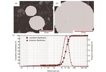
Siyu Chen, Yelin Xia, Xingyu Liu, Jianbo Lei, and Tao Wang
ObjectiveNiCu alloy is a crucial material used in the aerospace industry and petrochemical and other fields because of its excellent corrosion resistance, thermal conductivity, and ductility. However, problems of low hardness and poor wear resistance need to be solved to extend its service life and expand its scope of application. Currently, laser-directed energy deposition (L-DED), with a Gaussian or near-flat-top laser heat source, is applied to fabricate metal-ceramic composites to improve their performance, and the ceramic particles employed include tungsten carbide (WC), titanium carbide (TiC), and titanium nitride (TiN). However, proven drawbacks have been reported using these heat sources; these include easily emerging cracks, higher temperature gradient, greater residual stress, and an uneven distribution of WC particles. Meanwhile, laser oscillation provides a new technological approach for L-DED. Some research has offered evidences that employing this advanced technology in L-DED can mitigate the above-mentioned defects. In this study, NiCu alloy and NiCu/30%WC composite materials are fabricated by L-DED with a circular oscillating laser beam to improve the hardness and wear resistance of NiCu alloy and reveal the strengthening mechanism. This work can provide technical and data references for the preparation of new wear-resistant composite materials.MethodsThe experimental materials are NiCu alloy powder and spherical WC particles (Fig.1), with average particle sizes of 45-106 μm and 53-109 μm, respectively. A circular oscillating laser beam is chosen as the heating source to conduct the experiment, and the process parameters are given in Table 2. The laser beam shape is converted into a circular ring by a pair of scanning galvanometers. Upon irradiation with the high-energy laser, the substrate is partially melted, resulting in the formation of a molten pool on the surface. Compared with a Gaussian laser, forced convection occurs in the molten pool as a result of the stirring effect of the circular oscillating laser beam (Fig. 2). The phase composition, residual stress, microstructure, microhardness, and friction and wear of NiCu alloy and NiCu/30%WC composite materials are ascertained using an X-ray diffractometer (XRD), an X-ray stress tester, a scanning electron microscope (SEM), a microhardness tester, and a pin disk wear testing machine, respectively (Fig. 3). The impacts of the circular oscillating laser and WC particles on the phase composition and microstructure of NiCu alloy are investigated, along with their effects on the strengthening mechanism of its microhardness and friction and wear properties.Results and DiscussionsThe experimental results demonstrate that the NiCu/30%WC composite comprises NiCu eutectic, WC, W2C, and M23C6 phases (Fig. 4). By adding WC particles, the residual stress on the surface of the sample transforms from (44.5±12.0) MPa to (-212.4±19.0) MPa, the diffraction peak of the NiCu eutectic phase significantly shifts leftward, and the peak width increases. The reason for these changes is a combined effect of multiple factors of WC particles hindering grain growth and promoting grain refinement, lattice distortion, and dislocations.In addition, the stirring effect of the circular oscillating laser promotes convection in the molten pool, facilitates solute diffusion, decreases the temperature gradient, disrupts the columnar crystal structure, and provides more nucleation sites for equiaxed crystal growth. As a result, there is a uniform distribution of WC particles within the deposition layer (Fig. 5), and more equiaxed crystals are generated in the NiCu alloy (Fig. 6). Moreover, WC particles can also hinder grain growth, promoting the formation of more equiaxed crystals and cellular crystal around them (Figs. 6 and 8). Compared with the grain size (14.02 μm) of the NiCu sample, the average grain size of the NiCu/30%WC sample is 7.71 μm, a reduction of 45% (Fig. 7). Furthermore, partially decomposed WC particles and newly formed carbides are distributed in the structure (Figs. 9 and 10), encouraging grain refinement and improving the performance of the NiCu alloy.Moreover, the average microhardness value of the NiCu/30%WC deposition layer is 418 HV, which is 19% higher than that (351 HV) of the NiCu alloy (Fig. 11). The improvement in microhardness is a consequence of the joint action of fine grain strengthening and dispersion strengthening of WC particles and carbide. The results of friction and wear experiments indicate that the addition of WC-reinforcing particles greatly enhances the wear resistance of the deposition layer (Fig. 12). This is due to the ability of the unfused WC particles to hinder the wear of the NiCu alloy substrate by grinding balls, as well as the dispersion strengthening effect resulting from the formation of WC particles and carbides. This change in strengthening mechanism also leads to a conversion from adhesive wear, which occurs in the pure NiCu alloy, to abrasive wear (Figs. 13 and 14). As a result, the width of the wear scar slightly increases but the depth significantly decreases, and the mass loss is reduced by 56%.ConclusionsThe NiCu alloy and NiCu/30%WC composite is manufactured by L-DED using a circular oscillation laser. The results suggest that the stirring effect of the circular oscillating laser in the molten pool can effectively promote melt flow and enhance thermal convection, thereby reducing the temperature gradient, remelting columnar crystals to generate more fine equiaxed crystals, and refining grains to enhance performance. In addition, the WC particles and the generated reinforcing phases are also evenly distributed in the deposited layer under stirring, achieving dispersion strengthening. In summary, the properties of NiCu alloy are significantly improved through the combined effects of fine grain strengthening and dispersion strengthening.
Oct. 25, 2023Vol. 50 Issue 20 2002103 (2023)
Zhehe Yao, Jinyuan Hong, Weixin Fan, Yunfeng Liu, Deqing Mei, and Jianhua Yao
ObjectiveThe miniaturization and customization of corrugated sheets have become development trends to meet the demand of the high-efficiency heat and mass transfer in methanol reforming microreactors. To avoid problems such as springback, cracking, and wrinkling caused by conventional metal-forming processes, laser-forming technology becomes a potential solution to manufacture such structural components. However, when laser forming is adopted to fabricate specialty-shaped microcorrugated sheets, the sheets are prone to plane distortion defects owing to the uneven distribution of the energy input and free-end constraint in the curved scanning process. The plane distortion may lead to a gap between the corrugated sheets in the microreactor assembly, resulting in fluid leakage and a significant reduction in the heat and mass transfer performance of the microreactor. Because studies focusing on the laser forming of specialty-shaped microcorrugated sheets remain limited, the heat accumulation in laser scanning and the relationship between the temperature field and bending angle with various scanning strategies are analyzed in this study based on numerical simulations and experimental studies. A segmented variable-velocity strategy is explored to suppress the plane distortion. The forming quality of the corrugated sheets is further evaluated. This study provides a reference for the analysis and suppression of the plane distortion in the laser forming of specialty-shaped components.MethodsThe heat accumulation and temperature field distribution during the laser scanning along a double-arc curve are studied via numerical simulation, and the temperature difference between the top and bottom surface on the scanning path is analyzed using a segmented variable-velocity strategy. An experimental setup for the laser forming of a specialty-shaped corrugated sheet is developed (Fig. 6). The material of the specimen used in the experiments is 304 stainless steel with the size of 65.0 mm×65.0 mm×0.2 mm. A 1.5 kW oscillator continuous fiber laser with a laser power of 250 W and velocity range of 70-140 mm/s is used. Twelve cycles of scans are performed with the interval time of 10 s. During the experiments, one end of the sheet is fixed with a clamping width of 10 mm and can therefore be turned 180° using a three-jaw chuck. The laser scanning path can be drawn during the experiments and modeling process using the definition of a double-arc specialty-shaped line (Fig. 1). The x-directional and normal-plane bending angles are defined (Fig. 7), and the angles after laser forming are measured using a confocal microscope.Results and DiscussionsThe segmented variable-velocity strategy effectively reduces the heat accumulation in the scanning process along the double-arc curve by discretely controlling the energy distribution along the scanning line. Using the segmented variable-velocity strategy, the heat accumulation at the exit is reduced, and the overall peak temperature decreases (Fig. 3). In addition, the segmented variable-velocity strategy improves the uniformity of the temperature distribution owing to the varying laser irradiation time and heat input (Fig. 5). After the local thermal stress generated during the forming process is balanced by the constraint force of the free end to the laser heating location, a relatively uniform thermal deformation is generated along the scanning line, thereby suppressing the distortion of the forming plane during laser forming. Without considering the heat accumulation, the thermal stress must maintain a downward trend while balancing the binding force at each part of the scanning line (Fig. 4). Combined with the double-layer model, the variation trend of the bending angle of the normal plane depends on the change of the temperature difference (Fig. 5). The accuracy of the numerical model is verified by comparing the numerical simulation and experiment results of the sheet surface temperature during laser bending forming (Fig. 8). The results demonstrate that a suitable number of velocity-varying segments can balance the energy distribution and reduce the unevenness of the bending angle in the normal plane, whereas the velocity should be set within a reasonable range. The angular difference is reduced to less than 1.0°. The forming efficiency of the corrugated sheet is also improved by using the segmented variable-velocity strategy (Figs. 9 and 10). By using the segmented variable-velocity strategy, the parallelism between the top and bottom surfaces of the corrugated sheet increases by 87.5% and the waviness values of the bottom and wall surfaces decrease by a maximum of 51.2% (Figs. 11 and 12).ConclusionsA numerical model for the laser forming of a 304 stainless-steel sheet is developed, and the temperature distribution of the sheet at different numbers of velocity-varying segments is investigated. The results demonstrate that an increase in the segmental velocity can reduce the peak temperature of the top surface and heat accumulation at the exit. Meanwhile, the temperature gradient decreases as the velocity increases. Compared to constant-velocity scanning, the peak temperature at the terminal is significantly reduced by using the segmented variable-velocity strategy. For example, the peak temperature at the exit with eight velocity-varying segments is reduced by 13.4%. The experimental studies based on various scanning strategies and the detection of the normal-plane bending angle demonstrate that the distribution of the normal-plane bending angle is more uniform with an increase in the segmental number and velocity. Owing to the use of the segmented variable-velocity strategy, the forming plane distortion is significantly suppressed and the angle difference is reduced from 5.6° to 1.0° compared to constant-velocity scanning. Furthermore, the parallelism between the top and bottom surfaces of the corrugated sheet increases by 87.5% and the waviness decreases by a maximum of 51.2% by using the suppression strategy. The segmented variable-velocity strategy can be concluded to significantly improve the quality of specialty-shaped corrugated sheet forming.
Oct. 25, 2023Vol. 50 Issue 20 2002104 (2023)
Chenpeng Jia, Yiming Huang, Shengbin Zhao, Jiong Yuan, Feng Zhang, and Lijun Yang
ObjectiveIn the laser deep-penetration welding process, a high-energy-density laser produces intense melting and evaporation on the metal surface, generating a keyhole inside the molten pool. The keyhole gives rise to a plasma plume, composed of metallic vapor and plasma, induced by the evaporation and ionization of the molten metal. Previous studies generally believed that the plasma plume eruption process is periodic; however, elements of randomness are also present, specifically reflected in the random plasma eruption period and the difference in plasma plume eruption intensity. However, systematic research on the thermodynamic behavior of plasma plumes is still lacking. Therefore, it is of great significance to further study mass and energy transfer in laser welding by measuring the basic thermodynamic data of the plasma plume and analyzing its distribution.MethodsIn this study, a TC4 titanium alloy was used to study the thermodynamic behavior of a plasma plume in laser deep-penetration welding. A titanium alloy plate with a thickness of 3 mm was welded using an Nd∶YAG laser. During the welding process, a plasma photoelectric signal synchronous detection system with a passive dual-probe device was used to obtain the photoelectric information of the plasma plumes under different welding heat inputs. The thermodynamic parameters, including the eruption velocity and temperature of the plasma plume, were measured to study the thermodynamic behavioral characteristics of the plasma plume.Results and DiscussionsThe plasma plume expanded and contracted frequently during laser welding. In this study, the plasma eruption velocity and spatiotemporal distribution characteristics of the plasma plume temperature were studied by analyzing the characteristics of electrical signals in the plasma eruption process. Under the welding heat inputs of 75 J/mm, 50 J/mm, and 37.5 J/mm, the maximum probability plasma erupting velocity was 13 m/s, 14 m/s, and 15.5 m/s, respectively (Fig. 6). In the eruption process, the decrease degree of the plasma plume temperature (k) was primarily distributed in the range of above 0.5 (Fig. 9). The time interval for the two probes to sense the same plasma temperature exceeded twice the time it took for the plasma plume to make contact with both probes. Moreover, the maximum probability value of k decreased with an increase in welding heat input. In the late eruption period, the sequence of the two electrical signals that began to rise was closely related to the plasma eruption intensity (Fig. 10).ConclusionsIn this study, laser welding experiments on titanium alloys were conducted using a plasma photoelectric signal synchronous detection system, and the thermodynamic behavior of the plasma plume during laser welding was analyzed. Under the experimental parameter of 1500 W laser power and a welding heat input range of 37.5?75 J/mm, the main findings of this study are as follows.1) The plasma eruption velocity was mainly distributed in the range of 6?70 m/s. With an increase in the welding heat input, the maximum probability of the plasma eruption velocity tended to decrease, and there was no evident change in the distribution range.2) The temperature of the plasma plume decreased with an increase in the plasma plume size, and the decrease in the plasma plume temperature tended to decrease with an increase in the welding heat input.3) In the later stages of the plasma eruption process, when the electrical signal of the lower probe began to rise earlier than that of the upper probe, the plasma plume eruption was stronger; otherwise, the plasma eruption was weaker.
Sep. 25, 2023Vol. 50 Issue 20 2002105 (2023)
Zhaoyang Li, Zhongliang Li, Nan Nan, Teng Liu, Chenming Yang, Xinjun Wan, Yiheng Zhang, and Xiangzhao Wang
ObjectiveIn the laser welding, the welding fusion depth can characterize the weld bonding strength and affect the welding quality. An accurate measurement of the keyhole depth can prevent potential welding defects and improve the laser welding quality. However, conventional welding monitoring methods cannot achieve accurate keyhole depth measurements. The measuring beam of the optical coherence tomography (OCT) can be coaxial with the machining laser and has horizontal and longitudinal resolutions at the micron level. It is a proven detection method that can measure the keyhole depth in a nondestructive manner during welding, thus achieving a high-precision measurement of the keyhole depth. However, the multiple reflections of the OCT detecting beams in the metal keyhole, as well as the welding splash during the measurement process and other factors, may lead to the measurement signals of OCT not only containing the signals reflected from the bottom or side wall of the keyhole but also containing the metal vapor and welding splash reflections as well as the signals reflected from the inner wall of the keyhole. Consequently, OCT cannot accurately measure the depth of the bottom of the keyhole. To solve this problem, a method of laser welding keyhole depth detection using polarimetric OCT is proposed in this study, which eliminates the influence of multiple reflected lights on the keyhole depth measurement and improves the measurement accuracy.MethodsBased on the principle that the phase retardation of light reflected on a metal surface varies with the incidence angle, the polarization sensitive OCT (PS-OCT)system is used to image a laser-welded keyhole. Circularly polarized light is incident at the bottom of the vertical keyhole, and a phase retardation of π/2 is considered as the reference value. The phase retardation obtained from the keyhole measurements using PS-OCT is compared with the reference value. The PS-OCT signal corresponding to the phase retardation, which is the same as the reference value, is marked as the effective signal, and the remaining PS-OCT signal generated by multiple reflections is marked as an invalid signal. An effective PS-OCT signal is used to accurately calculate the keyhole depth. Two keyhole models of copper and aluminum are established, and a ray-tracing method is used to simulate the proposed method. Based on the simulation, a keyhole imitation sample is designed and the OCT is used to illustrate the multiple reflection artifacts of the sample. Subsequently, a PS-OCT experimental system is built, and M-scan- and B-scan measurements are performed at different positions of the samples using polarimetric OCT. The depth screened using the proposed method is compared with that using the commonly used 80-percentile filtering method.Results and DiscussionsSimulation parameters are determined based on the X-ray images (Table 1), and a ray-tracing simulation analysis is performed using a software [Fig. 4(a)]. The results demonstrate that the proposed method can significantly improve the accuracy of the keyhole depth calculation by screening the PS-OCT signals [Fig. 4 (c)] and is better than the current commonly used 80-percentile filtering method [Fig. 4 (b)]. The keyhole sample is designed [Fig. 6 (a)], and multiple artifacts in the keyhole are first described based on the scanning sample of an ordinary OCT system [Fig. 6 (b)]. Based on the established PS-OCT experimental system, M-scan imaging (Fig. 7) and B-scan imaging (Fig. 8) are performed at different locations of the samples, and the original PS-OCT images, corresponding phase retardation images, and PS-OCT images screened in this study are obtained. It can distinguish between single reflected signals, multiple reflected signals, and stray light signals in the keyhole, which effectively improves the accuracy of the keyhole depth measurement.ConclusionsThe existence of multiple-reflection artifacts is proven in the simulation, and the measurement errors of the OCT keyhole depth are 16.8% and 45.6% for copper and aluminum, respectively. The measurement errors of the keyhole depth are 3.27% and 6.42% for copper and aluminum, respectively, which are determined by using the 80-percentile filtering method. The errors in the keyhole depth measured by using this method are 1.05% for copper and 0.12% for aluminum. The designed keyhole samples are imaged using the established polarimetric OCT system. It is proven that multi-reflection artifacts are eliminated after screening by the proposed method, and a real image is obtained, which can reflect the real structure of the sample. The keyhole depth measurement error obtained using the original PS-OCT image combined with the 80-percentile filtering method is 23%, whereas that obtained using the proposed method is only 1.6%.
Oct. 25, 2023Vol. 50 Issue 20 2002106 (2023)
Caiding Ni, Zhaoxin Lao, Zhongguo Ren, Chao Chen, and Dong Wu
ObjectiveTemplate-guided capillary force-driven self-assembly technology is increasingly being considered as an alternative for fabricating a range of micro/nanostructures. Because of the advantages of rapid preparation of large-area and controllable complex hierarchical microstructures, the combination of femtosecond laser and capillary force-driven assembly (LPCS) technology has become an attractive method. In the LPCS method, the stability of the microstructure depends on the competition between the contact force, e.g., the van der Waals force, and elastic force of the microstructure after self-assembly. The contact force between microstructures is positively correlated with the contact area of the microstructure. A larger contact area corresponds to the larger van der Waals force and more stable assembly. When the contact area is greater than the critical value, the microstructure assembly behavior is irreversible. In our previous research, we found that microstructures with linear contact, such as microwalls, or even microstructures with surface contact could not be restored to the upright state after immersion in a liquid because of the large contact area after assembly, which greatly limits the application range of microstructures. In this study, the reversible self-assembly of linear contact microstructures prepared by LPCS is realized by taking advantage of the significant deformation ability of temperature-responsive hydrogels.MethodsIn this study, the temperature-responsive hydrogel is mainly composed of N-isopropylacrylamide, acrylamide, and phosphine oxide, where N-isopropylacrylamide is the monomer, acrylamide is the crosslinking agent, and phosphine oxide is the photoinitiator. We successively put the 400 mg N-isopropylacrylamide, 30 mg acrylamide, 30 mg phosphine oxide, and 450 μL glycol into a bottle and then place the bottle in a water bath at 50 ℃ for ultrasound. Finally, the 50 mg polyethylene pyrrolidone is added as a viscosifier. The femtosecond laser source used in the experiment has a pulse width of 75 fs, repetition frequency of 80 MHz, average output power of 2.5 W, and wavelength of 800 nm. The microscope system consists of a lens with a numerical aperture of 1.35. A scanning galvanometer is used to control the movement of the laser in the xy plane, and a nanostage is used to control the precise movement of the sample in the z direction to realize 3D printing of any shape. During processing, the measured average laser power is 24 mW, and the hatching distances used for anisotropic microstructures are 150 nm and 350 nm. After processing, the samples are placed in a developer (ethanol) for 10 min to remove any unpolymerized hydrogel.Results and DiscussionsWe investigate the effects of different hatching distances (HDs) on the degree of hydrogel polymerization. With an increase in HD, the shrinkage rate of the hydrogel increases. To achieve significant deformation and good surface appearance, HDs of 150 nm and 350 nm and their area width ratio of 3∶7 are selected, as shown in Figs.1(c) and (d). Anisotropic arm microstructures with a length of 30 μm are designed as shown in Fig.2. When the solution temperature is lower or higher than the critical temperature, arm bending deformation occurs in the opposite direction and exhibits good reversibility. In addition, the arm shows good transportation ability. As shown in Fig.3, we apply LPCS technology to temperature-responsive hydrogels to prepare a variety of assembly patterns. Compared with the traditional LPCS preparation, the requirements for spatial distribution are reduced. Finally, Figure 5 shows that based on the remarkable shrinkage property of temperature-responsive hydrogels at high temperatures, linear contact microgrippers with reversible assembly are prepared, and their applications in the field of microsensing are explored. Microgrippers with good airtightness and fatigue resistance can be repeatedly used.ConclusionsIn this study, anisotropic hydrogel microstructures are printed using a femtosecond laser, and the direction of their movement is controlled by temperature regulation to realize the directional transport of micro-objects. Second, laser-printed hydrogel microstructures are combined with capillary force-driven self-assembly to obtain rich micropatterns. This further demonstrates the flexibility of femtosecond laser two-photon processing and the convenience of preparing hierarchical microstructures combined with capillary force-driven self-assembly. More importantly, microgrippers with line contacts can be reversibly prepared using the deformation characteristics of temperature-responsive hydrogels. The closed microgrippers can be opened through the deformation force generated by the significant shrinkage of the hydrogel at high temperatures, which resolves the irreversibility of the assembly behavior of line contact microstructures prepared by the previous LPCS method. By sensing the surrounding environment, the microstructures can be closed and opened, greatly enriching the application of LPCS technology in the field of sensors.
Oct. 25, 2023Vol. 50 Issue 20 2002401 (2023)
Xiubao Zhao, Renchun Guo, Yuzhao Zhang, Jingang Wang, Jianchen Zheng, and Xiaoduo Wang
ObjectiveSoft microactuators, usually characterized by a small structural size and flexibility, have good application potential in biomedical fields, such as in drug delivery and tissue repair, and have therefore received significant attention from researchers. Hydrogels have good biocompatibility and are considered to be ideal materials for fabricating miniature flexible actuators. Hydrogels can not only be doped and chemically modified to impart stimulus responsiveness but also used to fabricate microscale soft actuators with certain deformation or actuation functions by optimizing their structural design. However, significant research efforts have focused on enhancing the material performance and optimizing the process, and only few studies have explored the effect of the actuator structure itself on its shape deformation capabilities. In this study, the design of a curved double-layer membrane structure is proposed based on the two-photon polymerization technology combined with the existing micro-robot bilayer membrane joint structure. A curved double-layer structure prepared from a pH-responsive hydrogel using optimized parameters exhibited 573% improvement in the deformation capacity compared with that of a straight-sided joint. This study provides a new design concept for the efficient driving and wide application of micro-robots.MethodsFirst, the effects of the laser power and scanning speed on the performance of the machined structures were explored. We varied the parameters to process a set of microhand-shaped structures. As shown in Fig.1(a), the scanning speed was varied from 10000 to 25000 μm/s at 2500 μm/s intervals, and the processing power was varied from 15 to 35 mW at 5 mW intervals. Figures 1(b), (c) show the optical and SEM images of the microhand-shaped structure. By varying the processing power and scanning speed, 35 sets of data were obtained with pH response thresholds between 7 and 8 for the pH-responsive materials used in the study [see Figs.1(d), (e)]. Different laser powers or scanning speeds allow the printing of sparse and dense layers with different crosslinking densities. The dense layer printed by increasing the laser power or decreasing the scanning speed increases the cross-linking density of carboxyl groups in the hydrogel, while the sparse layer printed by decreasing the laser power or increasing the scanning speed decreases the cross-linking density of carboxyl groups in the hydrogel. This allows the dense and sparse layers to undergo differential swelling in the same pH environment. In this study, the dense layer was processed using a processing power of 25 mW and a scanning speed of 10000 μm/s, and the sparse layer was processed using 20 mW power and a scanning speed of 22500 μm/s.Results and DiscussionsFirst, the initial degree of bending of the arc has a significant effect on the deformation capacity of the curved double-layer joint with the same arc length (Fig.2). To further investigate the effect of the initial bending degree on the deformation performance of the curved double-layer joint, the deformation performances of different curved structures were compared (Fig.3). Second, to verify the superiority of the bending deformation performance of the curved joints, we designed straight-sided joints and characterized the bending deformation of the latter using the same characterization method as that of the curved joints (Fig.4). In addition, to demonstrate the superior deformation capability of the curved joints, the data for the curved and straight-sided joints with the greatest deformation were obtained separately and compared (Fig.5). Furthermore, the dissolution curves of the curved joints with and without the double-layer structure were compared (Fig.6). Finally, the application of the curved joints in the structural design is demonstrated (Fig.7).ConclusionsIn this study, various curved double-layer joint structures were prepared by varying the laser power and scanning speed of a two-photon polymerization process of the two-photon polymerization printing technology. The effect of processing parameters on the deformation of the curved double-layer structure with the same length of the curved structure was systematically analyzed, and then the design of the curved double-layer joint was optimized. The experimental results reveal that the curved double-layer membrane joint has a greater bending ability. When the length of the curved structure is the same, the deformation performance increases with increasing central angle of the corresponding curved double-layer joint structure. The curved structure studied in this investigation can be applied with a central angle range of 180°?240° and exhibits the best deformation capability (central angle is 240°). The curved joints perform better than the conventional straight-sided joints, both in terms of the deformation capacity and number of cyclic deformations. Therefore, it is inferred that the arc-shaped joint structure can be a novel alternative for designing micro-nano-robotic joint structures that respond to pH and other stimuli, and they have good prospects in biomedical applications based on micro-nano soft body robots (e.g., drug delivery and tissue repair).
Sep. 25, 2023Vol. 50 Issue 20 2002402 (2023)
Jianfeng Gu, Jinpeng Fang, Chuanzong Li, Yue Wang, Zhixiang Gu, and Yi Xiao
ObjectiveIn recent years, bionic functional surfaces have played an important role in the manipulation of microfluidic dynamics. Among these, droplets and bubbles have been extensively studied as common interfacial fluids owing to their important application in fields such as droplet microreactors and cell screening . Therefore, it is highly meaningful to achieve a targeted transport and effective collection of droplets and bubbles. Researchers have achieved stable surface-wetting properties, as well as the ability to drive droplets and underwater bubbles simply and efficiently by preparing statically anisotropic structures. However, these static anisotropic structures are prepared by composite structures composed of multiple materials or by electrochemical etching. The preparation process is complex, susceptible to environmental pollution, and only a single target is considered, which significantly limits the application range. In this study, a static anisotropic superhydrophilic asymmetric double rail (SHADR) structure is prepared on the surface of a titanium sheet via nanosecond laser ablation. Based on the Laplace pressure gradient generated by the asymmetric structure, the SHADR structure achieves a spontaneous unidirectional transport of liquid droplets and underwater bubbles. This functional surface provides new ideas for microfluidic manipulation, biomedicine, and other fields.MethodsThe titanium sheet is ultrasonically cleaned in deionized water for 10 min to remove surface impurities before processing. A nanosecond fiber laser is used to vertically scan the surface of the titanium sheet to increase the surface roughness. Subsequently, the samples are ultrasonically cleaned once again and modified with a commercial superhydrophobic reagent to enhance the surface hydrophobicity and reduce the surface adhesion. Finally, the modified superhydrophobic surface is scanned using a nanosecond fiber laser-marking machine, and the SHADR structure with a length of 40 mm and an end spacing of 1 mm is processed. The contact angles of 5 μL water droplets on the surface of the titanium sheet are measured using a contact angle measurement system to characterize the surface wettability of the titanium sheet with different structures. The optical images of the droplets and motion of bubbles are captured by a high-speed camera.Results and DiscussionsInspired by the conical spines of a cactus and the long-billed beak of a bird, a simple and effective droplet and underwater bubble manipulation platform, that is, a SHADR struture, is prepared on the surface of a titanium sheet via nanosecond laser ablation (Fig.1). Using the Laplace pressure gradient generated by the static anisotropic structure, a SHADR structure achieves the spontaneous unidirectional transport of both droplets (Fig.2) and underwater bubbles (Fig.4). In this study, the effects of the structural parameters, such as the single-rail width (w) and branching angle (α), on the transport performances of the droplets and underwater bubbles are quantitatively investigated (Fig.3) and a simplified mechanical model is analyzed.ConclusionsIn this study, a simple and effective droplet and underwater bubble manipulation platform is prepared on the surface of a titanium sheet using nanosecond laser ablation.The SHADR struture enables the anisotropic spontaneous transport of droplets and bubbles based on the Laplace pressure difference. The droplet transport is recorded by a high-speed charge-coupled device camera, systematically quantifying the droplet transport performances in the horizontal SHADR struture under different parameters (branching angle, single rail width, and bubble volume). This functional surface is not only simple to operate but will also have wide applicability in the fields of microfluidics and interface science.
Oct. 25, 2023Vol. 50 Issue 20 2002403 (2023)
Wenbin Chen, Jijun Feng, Yang Liao, Xincheng Xia, Wei Jiang, Wenbo Ren, Tao Luo, and Xinluo Zhao
ObjectiveResearch on carbon nanotubes (CNTs) and graphene is very mature, and has led to substantive breakthroughs in electronics; however, some problems remain. For example, the experimental process for obtaining high-purity, semiconducting CNTs is complex, and the ability to adjust the bandgap of graphene is restricted. However, both these materials encounter limitations when used in electronic devices, among which, Young’s modulus and stiffness are the key criteria. Theoretical research has shown that polyynes exhibit better Young’s modulus and stiffness than graphene, CNTs, and diamond. In particular, polyynes have very high tensile strength, and their performance is unaffected by bending deformation, which cannot be achieved using CNTs and graphene. Thus, the limitations of single-walled CNTs (SWCNTs) and graphene can be overcome. Moreover, polyynes demonstrate excellent electrical properties (such as π-electronic system) and good hardness (i.e., 40 times that of diamond), providing potential applications in aerospace and nanotechnology. However, polyynes suffer from instability, high preparation costs, and low concentrations. In this study, based on femtosecond laser ablation technology, polyynes were prepared using a Ti ∶sapphire femtosecond laser with the repetition rate of 1 kHz to ablate SWCNTs suspended in methanol. The optimal laser power and processing time for preparing polyynes were explored, and the mechanism of polyyne synthesis was detailed, which will play an important role in the large-scale preparation of polyynes.MethodsVarious methods have been adopted to synthesize polyynes, which can be roughly divided into electrochemical (e.g., oxidation couples and electric arcs) and laser ablation (e.g., gas and liquid phases) techniques. Oxidation coupling is complex and impurities can be easily introduced. Arc discharge is commonly used to generate carbon chains, with the arc discharge in water. However, it cannot control the groups capped at both ends, which limits the stability and electronic properties of polyynes. For laser ablation, gas-phase facilities are complex, and typically require high airtightness and temperature control. Nevertheless, owing to its comparatively low cost, variety of target materials, and ablation surroundings, liquid-phase laser ablation has been widely employed to prepare carbon nanostructures at room temperature. Nanosecond and femtosecond lasers are the most commonly used to achieve this. However, nanosecond lasers have a significant thermal effect, which is not conducive to the formation of polyynes at room temperature. In contrast, femtosecond lasers have little thermal effect and high photon energy, which is beneficial for breaking the chemical bonds of SWCNTs for polyyne preparation. Accordingly, liquid-phase laser ablation with a femtosecond laser was selected for this study.Results and DiscussionsIn this work, for SERS characterization, the sample solution was mixed with a silver colloid at the volume ratio of 1∶5 and then spin-coated onto a silicon substrate for Raman spectrum measurement. The characteristic peak intensity of single-pulse laser energy increases with the increasing laser energy from 0.04 to 0.52 mJ, and decreases with the increasing laser energy from 0.52 to 1.48 mJ. When the single-pulse laser energy is 0.52 mJ, the highest intensity is obtained with the highest yield of polyynes. Because there is considerable overlap between the characteristic peaks of the short and long polyyne chains, further validation could be realized using the UV absorption spectrum. The corresponding absorption peaks of C8H2, C10H2, C12H2, C14H2, and C16H2 are approximately 225, 250, 275, 298, and 326 nm, respectively. Thus, long-chain polyynes containing more than 12 carbon atoms are generated. The characteristic peak of the C8H2 molecule was the most evident. In particular, the strongest peaks are realized for the ablation case with the pulse energy of 0.52 mJ, which is consistent with the SERS analysis. A pulse energy that is too low or too high deteriorates the generation of polyynes. Therefore, 0.52 mJ can be determined as the best single-pulse laser energy for preparing polyynes. The corresponding peak areas for sp and sp2 are further calculated. The peak area of sp carbon chain in the spectral range represents the polyyne concentration. The sp carbon peak area is the largest with the femtosecond laser ablation time of 1.5 h. This indicates that the optimal processing time is approximately 1.5 h. For the femtosecond laser with the repetition rate of 1 kHz, a continuous strong ionization region can be formed, where the laser pulse energy exceeds the saturation threshold (1.33×10¹⁵ W/cm2) and affects the connections between C2 radicals. Further increasing the laser power enhances the extent of fragmentation, but does not appreciably change the number of ionized molecules. Subsequently, the C2 radical is destroyed and cannot form sp orbital hybridization. Thus, the polyyne yield initially increases and then decreases. Moreover, with an increase in the ablation time, the bond would also be destroyed, and thus, the yield would decrease.ConclusionsLaser ablation of SWCNTs suspended in methanol was performed using a Ti∶sapphire femtosecond laser. From characterization via Raman spectroscopy, high-performance liquid chromatography, and ultraviolet absorption spectroscopy, linear hydrogen-capped polyynes (CnH2: n=6, 8,10, 12, 14, and 16) were confirmed, and the main product was C8H2.The highest yield of polyynes was realized at 1.5 h ablation with the laser power density of 1.33×10¹⁵ W/cm2. This saturation threshold may correspond to the extent of C2 radical fragmentation. The presented optimal laser ablation conditions for polyynes will facilitate the preparation of polyyne-based films and favor other practical applications.
Sep. 25, 2023Vol. 50 Issue 20 2002404 (2023)
Yunpeng Ren, Xincheng Tu, Kun He, Li Cheng, Yunxia Ye, Xudong Ren, and Naifei Ren
ObjectiveWith the rapid development of modern industrial technology, silicon carbide has broad application prospects owing to its excellent physical and chemical properties. Compared to conventional cutting methods, laser stealth dicing has the benefits of less debris with higher cutting accuracy. The research on the effect of laser parameters on surface ablation, edge chipping and cross-section roughness, and the development of new laser cutting techniques are of great practical significance to the development of silicon carbide cutting technology.MethodsIn this study a high power ultrafast laser processing system is used to cut out 300 μm thick SiC wafers with the diameter of 4 inch (1 inch=2.54 cm). Firstly, the effects of laser single pulse energy, feed distance, pulse repetition frequency, pulse width and scanning speed on cutting results are investigated using the control variables method. Based on the results of the multi-pulse mode (Fig.5(a)), the burst mode (Figs.5(b) and (c)) is used to reduce the edge chipping size and cross-section roughness. In burst mode, sub-pulses with the same pulse repetition rate as the output pulse sequence are selected from seed source pulses by adjusting the transistor-transistor logic (TTL)signal in the acousto-optic modulator (Fig.4). The surface ablation, edge chipping size and cross-section roughness are analyzed using laser confocal microscopy.Results and DiscussionsThe effects of laser single pulse energy, feed distance, pulse repetition frequency, pulse width and scanning speed on cutting results under the multi-pulse mode are investigated. If the pulse energy is lower than 4 μJ, modified layers cannot be formed inside the SiC wafers, resulting in failure to separate the wafer (Fig.6). The feed distance has little effect on kerf width, however, the significant effects on edge chipping size and cross-section roughness are observed (Fig.7). A too low or too high pulse repetition frequency results in large kerf width, large edge chipping size and high cross-section roughness (Fig.8). Appropriately increasing pulse width can improve the quality of surface, edge and cross-section (Fig.9). Utilizing the appropriate scanning speed can reduce kerf width, edge chipping size and cross-sectional roughness (Fig.10). Based on these results, the burst mode is used to cut the wafers. It is confirmed that the cutting accuracy significantly improves under the burst mode (Fig.11). Because interaction time between the laser and material is too short in multi-pulse mode, the density of free electrons is too low and the internal material modification is insufficient, which affects the quality of the edge and cross-section. The burst mode extends the interaction time between the laser and material which induces a high density of free electrons and good internal crack continuity. Therefore, the edge chipping size and cross-sectional roughness are reduced.ConclusionsThis study investigates the effects of laser pulse energy, feed distance, pulse repetition frequency, pulse width and scanning speed on the top and bottom surfaces, edge chipping and cross-section of SiC wafers in multi-pulse mode using the control variable method. It is identified that the best cutting results are produced under the single pulse energy of 6 μJ, +5 μm feed distance, 100 kHz pulse repetition frequency, 10 ps pulse width, and 100 mm/s scanning speed. The kerf width on the top and bottom surfaces is 15.9 μm and 5.1 μm, respectively, the top and bottom surface edge chipping size is 7.8 μm and 2.1 μm, respectively, and the cross-section roughness is 3.1 μm. To further improve the edge size and cross-section morphology, the burst mode effect on the cutting results is investigated. It is confirmed that burst mode improves the continuity of modified cracks and reduces edge chipping size. When the number of sub-pulses is five, the kerf width on the top and bottom surfaces is 21.4 μm and 7.6 μm, respectively, and the minimum edge chipping size on the top and bottom surfaces is 1.2 μm and 1.0 μm, respectively, which is 85 and 52% less than those under the same cutting parameters in multi-pulse mode. Also at five sub-pulses, the lowest cross-section roughness is 2.3 μm, which is 26% less than that under the same cutting parameters in multi-pulse mode. This is because of the high density of free electrons generated in multi-pulse mode, which results in full and homogeneous material modification, thus reducing cross-section roughness. The burst mode increases dimensionalities of the laser stealth dicing parameters compared with multi-pulse laser stealth cutting and facilitates better cutting results.
Oct. 25, 2023Vol. 50 Issue 20 2002405 (2023)
Yujie Fan, Bin Li, Junjie Lu, Jing Xia, Fanghua Liu, and Xiaohu Qiu
ObjectiveLaser process parameters have a significant effect on surface texture morphology. Existing research has focused on the influence of laser process parameters on the morphology of micropits and the processing mechanism. However, in the laser ablation of metal materials, the geometry and size of the surface texture are not stable with changes in the laser process parameters. To solve this problem, based on a laser ablation test, this study systematically investigates the influence of laser energy density on the evolution process of the surface texture geometry of GCr15 steel, analyzes the formation mechanisms of different morphologies, and describes the geometric size and shape stability of the surface texture of GCr15 steel, which provides a theoretical basis for the processing and size control of the surface texture of GCr15 steel.MethodsIn this study, GCr15 steel is used. First, the samples are ground and polished to avoid the additional influence of surface roughness and flatness on the laser ablation test. Second, a laser ablation test is performed on the pretreated samples. The laser energy density is increased from 54.585 W/mm2 to 473.968 W/mm2, spot diameter is 350 μm, pulse number is 1, and laser incident angle is 90°. After the ablation test, the surface texture of the ablated sample is analyzed and measured by a three-dimensional confocal microscope.Results and DiscussionsThe point texture of the laser ablation surface is mainly divided into four stages (Figs.2 and 3). With an increase in the laser energy density, the central region of the point texture changes from a pit to a bulge, gradually becoming a pit again, and finally becoming an irregular pit. The bulge structure of the edge region of the point texture becomes increasingly obvious with an increase in the laser energy density.The variation in the geometric size of the point texture differs at different stages (Fig.4 and Table 2). In the first stage, the laser ablation point texture forms a pit shape. When the laser energy density increases from 54.585 W/mm2 to 129.992 W/mm2, the diameter and depth of the point texture increase. The maximum pit diameter and depth are 342 μm and 73 μm, respectively. When the laser energy density increases from 129.992 W/mm2 to 151.113 W/mm2, the pit depth gradually decreases to zero. In the second stage, the laser ablation point texture has a bulge shape. When the laser energy density increases from 151.113 W/mm2 to 181.988 W/mm2, the height and diameter of the bulge gradually increase, and the maximum diameter and height are 513 μm and 97 μm, respectively. As the laser energy density continues to increase, the height and diameter of the bulge gradually decrease. In the third stage, the diameter and depth of the point texture are smaller than those in the first two stages, while the depth of the point texture changes significantly compared with that of the first two stages. The diameter of the point texture first decreases and then increases. The maximum diameter and depth of point texture are 220 μm and 127 μm, respectively. In the fourth stage, due to plasma shielding, the diameter and depth of the point texture change slowly with increasing laser energy density, and the diameter and depth of the pit remain stable at 216 μm and 156 μm, respectively.The average structure error of the point texture morphology first decreases and then increases with increasing laser energy density (Fig.10). When the laser energy density is 54.585 W/mm2, the average structure error of the point texture morphology is 3.16%. When the laser energy density reaches 181.988 W/mm2, the average structure error of the point texture morphology reaches its minimum value of 2.08%. When the laser energy density continues to increase from 233.985 W/mm2 to 363.977 W/mm2, the average structure error of the point texture morphology also increases from 5.03% to 8.03%.ConclusionsWhen the laser energy density is 181.988 W/mm2, the melt flow increases significantly with increasing laser energy density, the surface texture morphology changes from pit to bulge, the texture diameter and height reach their maximum values with increasing laser energy density, the average structure error of the morphology is minimized, and the single point morphology becomes stable. As the laser energy density increases to 223.985 W/mm2, the melt flow effect is strong, surface texture morphology changes from bulge to pit, texture depth increases sharply with increasing laser energy density, texture diameter decreases first and then increases, and the average structure error of the morphology reaches 5.03%. When the laser energy density exceeds 311.980 W/mm2, the geometric size of the pit changes slowly, average structure error of the morphology increases, and texture morphology structure becomes unstable.
Oct. 25, 2023Vol. 50 Issue 20 2002201 (2023)
Zhe Zhang, Qi Song, Kunpeng Zhang, Mei Xue, Yu Hou, and Zichen Zhang
ObjectiveSilicon is an important material utilized in various fields, such as biology and energy, particularly in the realm of integrated circuits. With advancements in semiconductor manufacturing toward large formats and thin substrates, the wafer-edge chipping and damage caused by traditional blade dicing have become increasingly significant in the field of semiconductor packaging. The introduction of low-dielectric-constant materials in the 90 nm integrated circuit technology node has presented a significant challenge to wafer dicing processes. The industry has responded by implementing a combination of laser surface grooving and mechanical dicing to address the low-dielectric-constant material separation issue. Laser processing equipment manufacturers have redirected their focus from nanosecond laser processing equipment toward ultrafast laser processing equipment that offers reduced thermal affected zones. However, existing research mainly focuses on optimizing the laser power, frequency, defocus, and feed speed, and comparatively analyzes multi-beam laser scribing spot distributions. A comprehensive theoretical analysis remains lacking. To address this gap, the current study utilizes a 517 nm femtosecond laser as a light source and shapes the energy of the focal spot into a flat-top distribution via a diffractive optical element for the surface grooving of silicon materials. The mechanism and quality of the groove process are investigated and discussed.MethodsThe experimental setup comprises a diode-pumped femtosecond fiber laser as the light source, while a galvanometer and an F-theta lens served as the beam movement and focusing tools. A diffractive optical element (DOE) is used to shape the near-focus spot into a top-hat square distribution on the surface of silicon for grooving. First, a one-dimensional simulation model is established using finite element analysis software, and the dual-temperature model is coupled with the excess carrier balance equation to analyze the interdependence among the material electrons, lattice, and carrier density in the femtosecond laser ablation process. This results in the establishment of a theoretical model for the femtosecond laser ablation process for silicon materials. Subsequently, a two-dimensional simulation model is established to simulate the morphology evolution during the silicon laser ablation process, and the impact of multipulse lasers with different spot intervals and energies on the groove quality is calculated. Finally, an experimental optical system is constructed for the grooving experiments, and the actual morphology is tested using a laser confocal microscope and the results are compared with those of the two-dimensional simulation.Results and DiscussionsThe one-dimensional model (Fig. 1) demonstrates that the temperature of the free electrons in the silicon material increases rapidly during the 517 nm femtosecond laser irradiation, reaching a maximum temperature of approximately 28000 K, while the lattice temperature remains constant. The energy of the electrons is transferred to the lattice system after the laser pulse, causing the temperature of the electrons to decrease and that of the lattice to increase (Fig. 2). This suggests that the femtosecond laser primarily damages the silicon material through electron excitation, thereby achieving "cold" processing and reducing thermal damage to the material. The two-dimensional model (Fig. 7) demonstrates that ablation occurs when the laser flux exceeds 0.3 J·cm-2 and the ablation depth increases significantly. The simulation results indicate that the thermal effect of the femtosecond laser ablation is small when the luminous flux is below 1.5 J·cm-2, and the ablation depth remains relatively stable (Fig. 8). The experimental results confirm that the top-hat square spot produces a flat-bottomed inverted trapezoidal groove with a width of approximately 35 μm and a depth of approximately 16 μm (Fig. 11). The sidewalls of the grooves are vertical and their shapes are consistent. However, the actual groove depth is slightly smaller than the depth calculated from the two-dimensional simulation model owing to the non-ideal fluence distribution of the light spot and the presence of plasma clusters generated during processing. These results indicate that the model produces better results with fewer processing pulses.ConclusionsThis study proposes the use of a DOE element to shape a femtosecond Gaussian spot with a wavelength of 517 nm into a top-hat square spot to achieve laser grooving on silicon surfaces. First, a theoretical model for the femtosecond laser ablation of silicon materials is established. The simulation results demonstrate that the femtosecond laser can excite a significant number of free electrons within the pulse duration, causing the electronic system temperature to surpass the damage threshold, while the crystal lattice temperature remains constant. A flat-top Gaussian distribution function is utilized to establish a two-dimensional flat-top spot ablation model, and the laser single-pulse ablation depth is calculated. The results indicate that the ablation groove shape of the flat-top square spot closely resembles an inverted trapezoid, with a high energy utilization rate and a linear relationship between the ablation depth and the number of pulses when the number of pulses is small. A self-constructed silicon wafer femtosecond grooving system is used to adjust the grooving process by modifying the processing speed of the galvanometer and laser power at a constant laser frequency. Under the conditions of an incident light power of 22 W and a stage speed of 2000 mm/s, silicon wafer grooving is obtained with a high groove bottom level, good side wall verticality, and a depth of 16 μm. The experiments demonstrate that the use of flat-top laser grooving significantly improves the processing efficiency and spot utilization, with a flat groove bottom and vertical side wall, which are advantageous for subsequent processing technologies.
Oct. 25, 2023Vol. 50 Issue 20 2002202 (2023)
Peng Zhao, Shouren Wang, Gaoqi Wang, Zhen Xiao, Shaoping Gao, and Xiaoping Liu
ObjectiveWith the increasing demand for automobiles, automobile brake discs are increasingly being used. The weight of traditional gray cast iron brake disc is 4-5 times that of aluminum alloy casting brake disc. Lightweight car design not only reduces energy consumption but also enable cars to achieve faster initial speeds. However, when excessive wear occurs on the surfaces of brake discs, the braking distance is significantly affected, which impairs driver safety. Compared with those of traditional gray cast iron brake discs, the hardness of aluminum alloy brake discs is low and the wear resistance is poor, and these are more likely to cause plastic deformation and other problems in cars. Thus, the application and development of aluminum alloys for use in car brake discs are greatly limited. As a new surface modification technology, laser cladding can be used to clad aluminum alloy brake disc surfaces with stronger mechanical and anti-wear properties. Not only can this technology reduce the weight of brake discs, it also can overcome the shortcomings of aluminum alloy brake discs and address actual working conditions. In this study, Al-Si-Ni-WC composite coating is prepared on the surface of the ZL108 aluminum alloy using laser cladding technology, where the hardness and wear resistance are greatly improved.MethodsFirst, a ZL108 aluminum alloy sheet is used as the matrix material, which is prepared according to the proportions listed in Table 2. It is then placed in a ball mill for mixing for 6 h and dried in a drying oven for 5 h. The experiment is conducted using the fiber laser cladding equipment with a maximum laser power of 2 kW. After the coating is prepared on the Al alloy plate, it is cut along the direction perpendicular to the laser-scanning direction. After the sample is obtained, the surface is polished using SiC sandpapers. The polished sample is then placed in a prepared Kellers reagent for surface corrosion, and the surface microstructure is observed. The morphology is observed using scanning electron microscopy (SEM), and the phase composition of the substance and hardness of the cladding coating surface are measured using an X-ray diffractometer (XRD) and dimensional hardness tester, respectively. A friction and wear testing machine is used to test the friction and wear properties of the samples. A GCr15 steel ball with a hardness of 240 HV and diameter of 4.6 mm is used as the friction pair during the test. The load is 20 N and the wear time is 20 min. Finally, the substrate and coating materials are tested through electrochemical experiments using a NaCl solution at normal temperature to analyze their corrosion resistance.Results and DiscussionsFollowing the hardness test and friction and wear test on the cladding coating and substrate, it is found that the Al-18%-Si-30%-Ni-5%-WC composite coating forms a more uniform cladding surface. The main phases in the coating include AlNi, AlNi3, WC, SiC, and other hard alloy phases, and the hard alloy phases generated in-situ are evenly distributed within the cladding layer. The substrate and coating bond tightly, and the grains inside the cladding coating are refined. In addition, the average hardness value of the cladding coating surface is found to be 272 HV when the mass fraction of Ni is 30%, which is 3.1 times the average hardness value of the ZL108 substrate surface, and the hardness values of the cladding coatings increase with an increase in Ni content. The wear volume of the composite coating is approximately 1/4.47 of that of the matrix, and the wear volume at high temperatures is lower than that at the normal temperature. The main reason for this is that Ni, which has strong high-temperature resistance, is added to the coating. Meanwhile, hard phases such as WC and SiC generated in situ also significantly improve the wear resistance of the coating.ConclusionsCompared with that of the ZL108 aluminum alloy, the hardness of the coating prepared by laser cladding technology is greatly improved. NiAl, Ni3Al, SiC, and other hard phases generated in situ inside the coating are evenly distributed inside the coating, thereby supporting and strengthening the coating. The main wear mechanisms of the substrate and cladding coating at room temperature are found to be abrasive wear. The wear mechanism of the substrate at high temperatures is adhesion wear and a small degree of oxidative wear, whereas the wear mechanism of the coating mainly consists of abrasion, oxidative, and adhesion wear. With an increase in ambient temperature, the thermal oxidation reactions are aggravated, and composite oxide films are generated by the coating, which alleviates the friction loss derived from adhesive and abrasive wear. This results in a lower wear volume at high temperatures than at room temperature. In the saturated NaCl solution, the corrosion resistance of the coating is significantly higher than that of the substrate. The improvement in corrosion resistance greatly increases the service life of the brake disc.
Oct. 25, 2023Vol. 50 Issue 20 2002203 (2023)
Fuyu Ye, Jian Yang, Panjie Sun, Xingyu Wang, and Chengyun Cui
ObjectiveTo improve the relatively low hardness and unsatisfactory wear resistance of 304 stainless steel, corresponding surface coatings with high hardness and wear resistance are prepared in this study using the laser cladding surface modification technology. Accordingly, the service life of 304 stainless steel is extended. Medium-entropy alloys (MEAs) are derived from high-entropy alloys (HEAs) and primarily comprise three to four major elements. Compared with traditional alloys, MEAs have unique phase structures and excellent mechanical properties. Based on the design concept of HEAs with unequal atomic and eutectic structures, Ta is incorporated into FeCrNi MEAs and its content is adjusted to realize FeCrNiTax eutectic medium-entropy alloy coatings (EMEACs). Using this in-situ nanoscale laminate structure which combines both soft and hard phases, the overall strength and wear resistance of the alloy are greatly improved, while considerable plasticity is maintained, achieving a balance between strength and plasticity. In addition, the rapid laser cladding solidification technology is beneficial for refining the characteristic structure and improving the mechanical properties of the coating.MethodsIn this study, five FeCrNiTax (atomic fraction x=0, 0.2, 0.4, 0.6, and 0.8) alloy coatings with varying Ta contents are designed as research samples. The 304 stainless steel is chosen as the substrate for laser cladding. Elemental powders with different components are uniformly mixed and preplaced on a polished substrate using a planetary ball mill. The coatings are prepared using a laser cladding device with the laser power of 1400 W, scanning speed of 8 mm/s, spot diameter of 3.6 mm, and overlap rate of 35%. The crystal structures of the coatings with different Ta contents are analyzed using X-ray diffractometer (XRD), and their microstructures and chemical compositions are characterized via scanning electron microscope (SEM). Subsequently, the Vickers hardness values of the coatings from the cladding layer to the substrate are measured using a Vickers hardness tester and the change curves are recorded. Finally, a friction and wear tester is employed to measure the friction coefficients of the coatings, and an electronic balance is used to measure the mass loss. The wear morphologies and elemental compositions of the coatings are then characterized using SEM and XRD .Results and DiscussionsFrom the XRD patterns, only the face center cubic (FCC) phase diffraction peak is detected for the FeCrNi MEAs. After the addition of Ta, the Laves phase corresponding to the hexagonal structure appears when x=0.2, and the respective diffraction peak becomes clearer with increasing Ta content. Meanwhile, the FCC phase diffraction peak continuously weakens, indicating that the volume fraction of the Laves phase increases from x=0.2 to x=0.8 (Fig. 2). A clear boundary line between the coating and substrate is observed in the cross section of the laser-melted alloy coating (Fig. 3), indicating good metallurgical bonding of the alloy. Moreover, the microstructure of the coating cross section (Fig. 4) shows that the primary phase is the FCC phase when x=0.2, accompanied by a small amount of the Laves phase, which is a typical hypoeutectic structure. With increasing Ta content (x=0.4), the Laves phase increases significantly and a completely layered eutectic structure forms. When the Ta content further increases, the primary phase also changes from the FCC phase to the Laves phase, and large Laves phase blocks precipitate in the structure, forming a peritectic structure. From the hardness measurement results of the coatings (Fig. 7), the corresponding curves generally show a downward stepwise distribution, and the higher the Ta content, the higher the hardness value. The alloy with x=0.2 exhibits the highest hardness value of 705.3 HV, approximately 3.7 times that (190 HV) of the 304 stainless steel substrate. In addition, the improvement in hardness significantly influences the wear resistance (Fig. 9). The wear surface of the substrate exhibits obvious plastic deformation and severe adhesive wear. After the addition of Ta, the wear of the coating decreases. The coating with x=0.8 is generally smoother and flatter with the best wear performance, and the wear mechanism is slight adhesive and oxidative wear.ConclusionsIn this study, FeCrNiTax EMEACs with different Ta contents are successfully prepared on the surface of 304 stainless steel using the laser-cladding technology. The coating exhibits good metallurgical bonding with the substrate and no obvious defects appear on the surface. The microstructural analysis shows that an increase in the Ta content results in the transition of the coating structure from the sub-eutectic to fully eutectic, and finally to super-eutectic structure. In addition, the coating hardness gradually increases with increasing Ta content, and the hardness value of 705.3 HV is the highest when x=0.8, which is approximately 3.7 times that of the 304 stainless steel substrate. The solid-solution strengthening and precipitation strengthening caused by the addition of Ta are important factors in improving the coating hardness. Regarding the wear resistance of the coating, the Laves phase generated by the addition of Ta has an inhibitory effect on the coating wear, and the friction coefficient is the lowest and the wear resistance is the best when x=0.8. The wear mechanisms mainly include adhesive and oxidative wear.
Oct. 25, 2023Vol. 50 Issue 20 2002204 (2023)
Wei Gong, Wenhua Zhao, Xintian Wang, Zhenze Li, Yi Wang, Xinjing Zhao, Qing Wang, Yanhui Wang, Lei Wang, and Qidai Chen
Artificial intelligence technology provides a new idea to solve the bottleneck problem in the current laser processing field, and has a significant supplementary effect on laser micro/nano processing. It performs tasks through statistical techniques and numerical algorithms, without explicit program instructions, and can realize prediction, optimization of processing parameters and construction of complex dynamic models. For example, neural networks is used to model the physical process of laser-matter interaction without the physical model. Machine learning-based classification technology has significantly accelerated the intelligent process of defect detection in laser processing, and significant innovation has been achieved in the traditional laser processing process control method that relies on pre-defined processing paths.Progress With artificial intelligence technology development, laser industrial manufacturing intelligence has become an important trend. Machine learning, as one of the main artificial intelligence technologies, is widely used in related fields, promoting a significant breakthrough and demonstrating specific potential to drive the next generation of ultrafast laser processing technology. This study therefore reviews key machine learning applications in various processes in the laser-micro and nano-processing field. This includes laser processing parameter optimization and process window prediction, real-time monitoring and control of the processing process, processing results prediction, and the investigation of auxiliary physical mechanisms. It summarizes and anticipates future applications and currently available improvement solutions where machine learning and laser processing are expected to intersect.Conclusions and Prospects Firstly, intelligent laser micro/nano machining is an interdisciplinary direction, encompassing the two major fields of laser micro/nano processing and artificial intelligence. In recent years, the technological advancement of laser micro/nano processing has been relatively slow compared to that of artificial intelligence. Therefore, to promote the development of laser micro/nano processing research, it’s a good choice to continuously keep up with the advancements in artificial intelligence. Secondly, because the neural network approach is data-driven, model generalizability and accuracy are directly related to the amount of available data. The model generation method enables data augmentation and the random generation of new data that is extremely similar to the training data, thus artificially expanding the dataset. Finally, although deep learning is an extremely useful machine learning model, its “black box” nature prevents users from effectively controlling the neural network, hence, this has created doubts including skepticism regarding the “black box” concept. Consequently, artificial intelligence technology represented by machine learning technology has begun to empower all stages of laser micro/nano processing. In the future, it is expected to bring innovation to the process of laser micro/nano processing and form a new model of “artificial intelligence-driven scientific research”.SignificanceSince laser was invented, laser processing has completely transformed technologies such as cutting, cleaning, drilling, engraving, ablation, additive manufacturing, and welding. Laser technologies are used in a wide range of applications including aerospace, automotive, electronics, batteries, medical, 3D printing, semiconductors, sensors, and solar energy. With the development of technology, laser micro/nano processing is developing in the direction of finer (from millimeter to micron or even nanometer), more efficient (processing speed of hundreds of square millimeters per second), conformal (three-dimensional), and random (multiple materials) . However, due to the complexity of the physical mechanism of the interaction between laser and matter, its further development is restricted, accurate modeling cannot be achieved, and there are still obvious deficiencies in processing quality and conformal processing.
Oct. 25, 2023Vol. 50 Issue 20 2000001 (2023)
© Copyright 2018-2021 | Chinese Laser Press.
All Rights Reserved 沪ICP备15018463号-20