


Please enter the answer below before you can view the full text.

Boyu Liu, Xiangming Wang, Guang Yang, and Bendong Xing
SignificanceOwing to the continuous developments in the Chinese aerospace industry, aviation structural parts need to ensure lightweight, high efficiency, long flight time, and high maneuverability characteristics. Therefore, it is a significant challenge in structural optimization design to further reduce the structural quality coefficient. Traditional lightweight designs are mostly based on the replacement of classical structures with equivalent parts, such as lean improvement and excavation of structural potential using the new processes and new materials, and have now approached the “ceiling”.Topology optimization technology, as an important branch of structural optimization design, determines the optimal material distribution and best load-bearing path by defining material properties, load conditions, and constraints. It is an effective design method for obtaining lightweight structure design and high-performance innovative configurations, and has been widely used in aerospace, automobile manufacturing, and other fields.However, topology configurations are usually complex. Limited by traditional manufacturing processes, designers often need to simplify the optimal topology configurations, which fails to fully reflect the structural advantages of topology optimization design. Additive manufacturing technology uses high-energy laser beams and adopts the superposition mode of “bottom to up” layer-by-layer material melting, which can realize rapid prototyping and solid-free manufacturing of complex topology configurations without molds. This method addresses the problem of “manufacturing determines design” in structure optimization, which greatly broadens the design space. However, additive metal manufacturing technology is not completely a “free manufacturing” technology, and it is limited by unique manufacturing constraints. Therefore, considering additive manufacturing constraints in topology optimization design, researching and developing topology optimization design for additive metal manufacturing has a broad application prospect.ProgressThis study reviews the progress of structural topology optimization design for metal additive manufacturing technology. First, it summarizes the common methods and characteristics of continuum structure topology optimization (Table 1) and compares the cantilever beam topology optimization results obtained with different methods (Fig.1). From the perspective of optimizing topology algorithms, it concludes the effective measures to improve structural continuity and manufacturability based on topology optimization methods of elements and boundary evolution (Figs.2-4). Then, it expounds on the principle, processing characteristics, and application range of the mainstream metal additive manufacturing technology (Fig.5). After that, it summarizes the topology optimization methods considering the geometric size (Fig.8), structural forming (Figs.9 and 10), and material property constraints (Fig.11) of metal additive manufacturing technology (Fig.7 and Table 2). Finally, it prospects the development directions of metal additive manufacturing and topology optimization technology.Conclusions and ProspectsIn this study, the structural topology optimization of an advanced design technology is integrated with the metal additive manufacturing technology that is an advanced manufacturing technology. This study summarizes the methods, characteristics, and improvement measures of continuum structure topology optimization design. Moreover, it expounds on the principle, characteristics, and application of metal additive manufacturing technology. In addition, it summarizes and prospects the topology optimization methods considering the constraints of metal additive manufacturing, which will provide a reference for researchers to further study the topology optimization design for metal additive manufacturing technology.Topology optimization design has shortcomings of numerous design variables, weak convergence, and low computational efficiency. It is often difficult for existing topology optimization algorithms to output the optimal structural performance solution that can be directly used in additive manufacturing. Therefore, combined with the parallel computing technology, it is crucial to carry out algorithm research with fewer design variables and better convergence, and output the optimal solution that can be directly used in additive manufacturing.The research on macroscopic topology optimization and microscopic lattice structure is becoming increasingly improved. By effectively integrating the two, fully leveraging the high-performance configurations of topology optimization design and broad design space provided by additive manufacturing technology, the pursuit of high-performance lightweight design has broad development prospects.The topology optimization methods considering the constraints of metal additive manufacturing adopt relatively ideal material models, which differ from the actual printing materials used in metal additive manufacturing technology. Therefore, establishing a precise topological model of material anisotropy under multiple process parameters, quantification of process parameters of metal additive manufacturing equipment, simulation of the metal additive manufacturing process, and prediction of warping deformation and cracking of parts can effectively reduce residual stress and deformation, and improve forming accuracy and surface quality.Topology optimization design for metal additive manufacturing technology is often based on the optimization of a single material. Effectively combining multi-material topology optimization and metal additive manufacturing, studying the topology optimization design and metal additive manufacturing technology of functional gradient materials, and realizing the integrated design of materials, structure, process, and performance, are breakthrough points in the pursuit of high-performance, multi-function, and lightweight.
Jun. 25, 2023Vol. 50 Issue 12 1202301 (2023)
Jun Li, Tingting Liu, Wenhe Liao, Huiliang Wei, Jinhui Xu, and Qingyuan Yin
ObjectiveGH3536 superalloy is a typical difficult-to-machine material with high micro-strengthening phase hardness, severe work hardening, high shear stress resistance, and low thermal conductivity. When processing GH3536 superalloys using traditional methods, problems such as low-quality machined surfaces and serious tool breakages are often encountered. The preparation of GH3536 superalloy parts using selective laser melting (SLM) has become an important research topic. However, forming defects of the structural parts of SLM restrict the rapid manufacturing and application of nickel-based superalloys. Hence, research on the corresponding basic scientific issues is urgently required. This study focuses on the forming process of GH3536 superalloys; the printing process of an SLM GH3536 alloy is systematically studied by simulating the temperature and flow fields in the transient process and typical experiments. Heat transfer, liquid metal flow, the formation of inter-track pore defects, and temperature-time variations are explored, providing a basis for the optimization of the manufacturing process parameters and the improvement of the manufacturing quality.MethodsNumerical simulation can comprehensively reveal the complex changes in the temperature and stress fields during the printing process and visualize multi-physics and molten pool's behavior and distribution characteristics under dynamic control conditions, and then support the prediction and real-time control of manufacturing defects. Our simulation can be summarized in the following steps. First, a heat and mass transfer model was established to simulate the SLM GH3536 superalloy printing process. Second, the temperature and flow fields of the molten pool during SLM were studied by changing the laser power, scanning speed, scanning distance, and number of printing layers. Finally, the GH3536 SLM experiment was carried out, and the deposition morphologies were characterized using an optical microscope. The simulation and experimental data deepened our understanding of the temperature and flow fields of laser additive manufacturing and the mechanism of their correlation with defects.Results and DiscussionsComputational fluid dynamics is widely used to simulate the heating and melting effects of a laser on metal particles, enabling the complex flow behavior of liquid metal between particles to be studied. In this paper, a heat-flow coupled model at the powder scale is established to simulate the printing process of an SLM GH3536 superalloy (Fig. 1). As the scanning speed increases from 0.94 m/s to 1.25 m/s, the width of the molten pool formed by a single-layer and single-pass SLM decreases from 126 μm to 113 μm, and the depth of the molten pool decreases from 86 μm to 60 μm (Fig. 2). When the laser power increases from 190 W to 250 W, the width of the single-layer and single-track increases from 126 μm to 140 μm, and the depth of the molten pool increases from 86 μm to 93 μm (Fig. 5). When the scanning distance is 110 μm for multi-layer and multi-track printing, some unmelted powder and surface-pore defects occur in the intertrack (Fig. 9). Using key parameters such as laser power, scanning speed, scanning distance, and the number of printing layers, changes in the flow of molten pool and temperature field during SLM are studied to comparatively analyze pore distribution under different conditions.ConclusionsTo achieve the forming quality and process parameter optimization requirements of an SLM GH3536 superalloy, we study the characteristics and defect formation mechanisms of the printing process of a GH3536 superalloy under different process parameters. Our results find that the interaction time between the laser heat source and powder layer decreases as the scanning speed increases, which results in a decrease in the size of the molten pool; the photothermal action area increases with the increase of laser power, which results in an increase in the area of molten pool. For multi-layer multi-track printing, we used a laser power of 190 W, scanning speed of 1.08 m/s, and a scanning distance of 90 μm, which can remelt the deposited metal and eliminate some of the pores from the previous printed layer.
Jun. 25, 2023Vol. 50 Issue 12 1202302 (2023)
Fei Liu, Yichuan Tang, Haiqiong Xie, Chenke Zhang, and Junjie Chen
ObjectiveBecause of their excellent performance with lightweight and multifunctional integration, lattice structures have been widely used in aerospace, heat exchangers, and bone tissue engineering. Triply periodic minimal surface (TPMS) lattice structures with smooth surface morphology reduce the stress concentration under load, exhibiting higher specific strength, specific stiffness, and energy absorption capacity. Therefore, TPMS has potential applications in lightweight and energy-absorbing buffer devices in the aerospace industry. Sheet and network lattices have been proposed to utilize their advantages, which require further performance improvements with an optimal design. Thus, there is an urgent need to develop a reliable simulation analysis method to reveal the mechanism of structural strengthening and determine optimization direction.MethodsIn this study, a new surface offset method was developed to design a TPMS lattice structure (Fig. 2) to improve mechanical properties and energy absorption. Diamond, Primitive, Gyroid, and I-WP TPMS lattice structures (Fig. 3) were optimized using this method and fabricated via selective laser melting (SLM). The compression tests of the lattice structures were repeated three times to reveal the mechanical properties. In comparison, finite element models with the Johnson-Cook model were established to reflect the deformation behaviors of the lattices and predict their mechanical strength, as confirmed by the experimental results. In this study, the influence of surface offset design on the mechanical properties and energy absorption capacity under quasistatic compression was investigated, which provided insight into the optimization strategies and analysis methods of lattice structures.Results and DiscussionsThe experimental and simulated compression stress-strain curves show that the finite element analysis method based on the Johnson-Cook model can precisely replicate the experimental results, including similar linear growth, stress drop, and stress plateau stages. The deviations in the mechanical strength of the lattice structures obtained via the experiment and simulation are all less than 14%, particularly for sheet structures, whose ultimate strength error is within 2%. This indicates that the finite element method can accurately predict the mechanical properties and deformation behavior of lattice structures.The mechanical properties of the four lattice types were improved significantly using the proposed design method, as can be seen from Table 4 showing the critical mechanical properties of all the samples. With the continuous increase in the surface offset, the mechanical strength of Diamond, Gyroid and I-WP lattices increase by 101.5%-244.9% owing to the increase in the second moment of area. Among them, the I-WP sheet 45-30 exhibits the most outstanding performance, demonstrating an increased mechanical strength (111.64 MPa) compared with that of the rod lattice (32.37 MPa). However, Primitive lattices significantly differ from the other three types. The surface offset helps to improve the stability of the Primitive lattices, avoiding the sudden collapse of the entire structure. The mechanical strength was increased by 47.1%, but continuous growth of the shell offset reduced the mechanical properties owing to the weakening effect of the plastic hinges.The cumulative energy absorption (Figs. 15 and 16) reveals that the surface offset design effectively improves the energy absorption capacity of the lattice structure. Specifically, Diamond, Gyroid, and I-WP continuously improve the cumulative energy absorption by 139.8%, 279.2%, and 312.9%, respectively, compared with the corresponding rod-type lattices. Similar to strength, the most outstanding performances are contributed by the I-WP sheet 45-30, whose cumulative energy absorption increases from 11.32 to 46.72MJ/m3, and the plateau stress (σpl) increases from 22.68to 98.81 MPa.These results highlight the optimization effect of the surface offset on the energy absorption capacity. The shear failure mode of rod-shaped lattice structure changes into the deformation behavior of layer-by-layer collapse using this method. The large-scale collective collapse of lattice structures can be prevented to obtain a smooth, continuous stress-strain curve, which increases the plateau stress of the sheet lattices.Conclusions1. In compression experiments, the rod lattice structure is prone to a 45° shear fracture. A continuous surface offset can effectively improve the deformation behavior of an abrupt collapse, enhance the mechanical strength and plateau stress, and increase the energy absorption capacity.2. The simulation analysis method based on the Johnson-Cook plasticity and damage model can accurately predict the mechanical strength and energy absorption performance of the TPMS lattice structure, revealing the failure process and fracture behavior of the lattices. This provides essential guidance for structural optimization and performance improvement.3. The I-WP sheet exhibits the best performance among the four typical TPMS lattice structures through surface offset. Compared with rod-shaped lattices, the mechanical strength, plateau stress, and energy absorption of sheet-shaped lattices increased by 244.9%, 335.7%, and 312.7%, respectively. This is mainly attributed to the transformation of the deformation mode contributed by the surface offset, which minimizes the 45° shear fracture behavior and improves the plateau stress of the lattice structure, accompanied by a layer-by-layer collapse for deformation optimization.In summary, the surface offset design and Johnson-Cook simulation model were adopted for TPMS lattices in this study, which provides a reference for optimization strategies of lattice structures. Further studies on the fatigue performance of TPMS lattice structures should be conducted to facilitate the development of new lightweight structures in laser additive manufacturing.
Jun. 25, 2023Vol. 50 Issue 12 1202303 (2023)
Shijie Qi, Lin Xiong, Mingyuan Chen, and Jikui Zhang
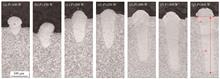
ObjectiveCompared with conventional fabrication methods, such as casting and forging, additive manufacturing (AM) presents high material utilization, outstanding mechanical behaviors, and near-net-shape fabrication; therefore, it has garnered considerable popularity in recent years. Laser powder bed fusion (LPBF) is common in metal AM and utilizes a scanning laser to melt parallel lines in each successive layer of powder, developing fine 3D structures with excellent material properties. The LPBF process exhibits a clear shortage in manufacturing efficiency, and numerous studies have been conducted to improve manufacturing efficiency by optimizing the process parameters. However, the design space of process parameters is limited because unreasonable parameters may lead to a lack of dimensional accuracy or internal defects. Therefore, studying the relationship between the process parameters and the quality of the formed parts is crucial. Most of the published studies focus on molten pools in “conduction mode”. The motion of “key-hole” mode molten pools, during which key-hole collapse may appear and lead to pore defects, still lacks sufficient investigation. In this study, experiments are performed to build the relationship between laser power and single-track morphology, thereby revealing the boundary of the parameter design space during the LPBF process. Furthermore, the key-hole motion behavior is exhibited with a finely built numerical model, and the formation mechanism of pore defects is analyzed. We hope this study will help in the optimization of LPBF process parameters and provide an academic reference for the analysis of pore defects.MethodsTC4 powder was used as a starting material. First, single tracks were fabricated using the LPBF method at various laser powers. Then, the samples were sliced and polished, and the cross sections of the single tracks were characterized using an optical microscope (OM). Subsequently, the depth and width of the single tracks were measured, and the relationship between these dimensions and process parameters was analyzed. Next, a finely built powder bed model was established to simulate the physical behavior within the molten pool. The accuracy of the numerical model was verified by comparing the dimensions of the molten pool acquired by simulation with the experimental results. In addition, the morphology of the molten pool was analyzed using a numerical model, and the development of pore defects was investigated.Results and DiscussionsWhen the laser power grows from 100 W to 400 W, the depth of the single-track increases from 40 μm to 348 μm (Fig. 2). The width of a single-track grows from 82 μm to 97 μm when the laser power increases from 100 W to 150 W; however, when the laser power continues to increase to 400 W, the width increases slowly from 97 μm to 109 μm (Fig. 3). The simulation result is consistent with the experiment result, as the width acquired by the simulation shows a 5.8% deviation, while the simulated depth shows a 12.2% deviation. The simulation shows that as the laser power increases, the key-hole becomes deeper because of the stronger recoil force, which explains the reason for the sharp increase in single-track depth with the increase in the laser power. However, the energy travels slowly in the horizontal direction by heat conduction, and the single-track width shows no notable change when the laser power increases (Fig. 5). When the high laser power is adopted, a “J” shaped key-hole appears, and the collapse may occur at the bottom of the key-hole, with bubbles formed during the collapse persisting around the bottom of the key-hole and transforming into pore defects as the pool solidifies (Figs. 8 and 9).ConclusionsIn this study, single tracks are fabricated by the LPBF method using various laser powers and powder bed thicknesses, and a novel fine numerical model is established to analyze the physical phenomena within the molten pool. The width of a single-track shows no discernible change when the laser power increases from 150 W to 400 W, implying that the increase in hatch spacing is not feasible by continually increasing the laser power. Moreover, both the experimental and simulation results indicate that the depth of a single-track is sensitive to the laser power. When a low laser power (100-150 W) is used, the powder bed cannot fully melt, which may lead to unexpected unmelted regions in the fabricated structures. However, if the laser power is exceedingly high (350 W or more), the key-hole beneath the molten pool will be narrow and deep; this type of key-hole can easily collapse, and the air captured during the collapse may finally generate pore defects. Therefore, in this LPBF process (scanning speed is 1200 mm/s and laser diameter is 100 μm), 200-300 W is considered a reasonable design range for laser power. This study provides an academic reference for the design of parameters in the LPBF process.
Jun. 25, 2023Vol. 50 Issue 12 1202304 (2023)
Xiaohong Zhan, Yue Li, Yanqiu Zhao, Jianfeng Wang, Xuesong Gao, and Jun Zhou
ObjectiveHigh-strength 2195 aluminum-lithium (Al-Li) alloy exhibits excellent strength and fracture toughness both at room and low temperatures and is mainly used in the cryogenic storage tanks of space launch vehicles to satisfy the weight reduction requirements of key structures in the aerospace sector. Laser welding technology is a high-energy beam connection method with high energy density, good welding quality, high precision, high production efficiency, significant weight reduction, and other characteristics. Laser welding is an ideal joining technology for spacecraft tank structures. Alloying elements influence the type, size, volume fraction, and distribution pattern of precipitates in aluminum alloys, while precipitates and microstructures determine the mechanical properties of these alloys. Therefore, optimizing the composition of welded joints fabricated from 2195 Al-Li alloy can considerably improve the joint properties. In this study, 4047 filler wires and 2319 filler wires are used to conduct laser welding experiments on 2195 Al-Li alloy to compare and analyze the effects of different filler elements on the microstructure, alloy element distribution, and mechanical properties of laser-welded joints.MethodsThe dimensions of welded parts used in this work were 100 mm×50 mm×2 mm (Fig. 1). The utilized wires included 4047 filler wires with a diameter of 1.2 mm and 2319 filler wires with 2% (mass fraction) TiC particles. Al-Li alloy laser fillet welding was performed using a laser. Laser welding was conducted with a 6-axis robot, and the welded specimens were clamped using a special welding fixture. Wire-filling welding was performed using a wire feeder. Scanning electron microscopy (SEM) was conducted to observe the microstructure of the joint cross-section and tensile fracture morphology. The obtained tissue morphology was utilized to study the microstructural characteristics of joints with different welding wires and their tensile fracture mechanism. Chemical compositions of different areas in joint cross-sections were characterized by energy-dispersive X-ray spectroscopy (EDS) to determine elemental distributions and their influence on the joint properties.Results and DiscussionsLaser self-melting welding and laser welding with 4047 filler wire produce the microstructure with a fusion line passing close to the equiaxial fine crystal zone (EQZ), columnar crystal zone, and central dendrite zone (Figs. 4 and 5). The presence of EQZ near the fusion line is caused by the presence of Zr and Li elements in the alloy. The laser wire filling welding using 2319 significantly improves the properties of the welding seam (Fig. 6) containing fine equiaxial crystals owing to the addition of TiC particles to the center of the melt pool. This increases the number of nucleation centers and substantially compresses the growth space for columnar crystals, thus promoting the transformation of columnar branch crystals to equiaxial crystals. Grain boundary segregation and elemental burnout strongly influence the weld, leading to the redistribution of its elements and accumulation of Cu atoms at the grain boundaries (Tables 2-5). The 2195 aluminum-lithium alloy laser-welded joints undergo significant softening with a reduction in the number of strengthening phases due to the strong lithium and copper elemental burnout in the weld area and significant strength loss without wire filling. After wire filling, the mechanical properties of the joint are significantly improved owing to the refinement of weld grains and increase in the number of weld strengthening phases. In particular, using 4047 wires as a filler considerably increases the tensile strength of the laser-welded joints produced from 2195 aluminum-lithium alloy (Fig. 11).ConclusionsThe self-melting welding joint of 2195 aluminum-lithium alloy and joint by laser wire filling welding with 4047 consist of equiaxed fine crystals, columnar crystals, and equiaxed dendritic crystals. The laser wire filling welding joints using 2319 consist of equiaxed fine crystals and equiaxed dendritic crystals. In contrast to laser self-melting welding, the weld by laser wire filling welding using 2319 contains a large fraction of Cu atoms distributed at the grain boundaries with a Cu element supplementation rate of 6.5%. After 4047 wire filling, the 2195 aluminum-lithium alloy laser welding process is supplemented with Si atoms; the weld tissue grain boundaries contain a large number of Si atoms, and the Si phase strengthening effect is enhanced. Compared with laser self-melting welding, laser filler welding is more energetically intense, and its Li element burnout is more significant. Both 4047 filler wires and 2319 filler wires increase the tensile strength of the laser-welded joints fabricated from 2195 aluminum-lithium alloy with a stronger effect observed for the 4047 filler wires. As a result, the tensile strength of the 2195 Al-Li alloy laser-welded joints is 14.19% higher than that of the joints produced via laser self-melting welding.
Jun. 25, 2023Vol. 50 Issue 12 1202101 (2023)
Zhenjia Zhao, Baoqi Zhu, Jianglin Zou, Shihui Guo, and Hua Kong
ObjectiveLaser-arc hybrid welding combines a low-cost process-stable arc heat source with a highly efficient laser heat source, reducing the material demand for laser power and enhancing the material absorption rate of the laser. This increases the depth of fusion, enhances the welding speed, and improves the quality of the welding. However, due to the instability of the welding process, excessive spatter, humping, and porosity can occur, which seriously limit further development of this technology. The existence of pores inside the weld necessitates the use of instruments for detection, which increases the difficulty of detection and weakens the effective working section of the weld; this negatively impacts the strength and toughness of the joint. Studying the influence of porosity in composite welding is important for further understanding the physical process of laser-arc composite welding and the optimization of composite welding process parameters. In this study, the influence of laser-to-steam on composite welding keyhole porosity was investigated by linearly varying the laser power during the welding process. Subsequently, in combination with high-speed camera observation of the composite welding plasma morphology, the impact of the arc on the keyhole porosity was studied. Finally, considering the weld depth, weld width, weld formation and variation rules of porosity in the weld, the formation rules and influencing factors of keyhole porosity in the weld during the fiber laser-TIG hybrid welding were analyzed to establish the theoretical foundation for optimizing the laser-arc hybrid welding technology and understanding the energy coupling mechanism in laser-arc hybrid welding process.MethodsThe distribution of internal pores in the weld was first observed at different arc currents using a linearly varying laser power composite welding method. Then, the distribution of internal pores in the weld using fixed laser power composite welding and linearly varying laser power composite welding was compared, proving that the linearly varying laser power approach is feasible. Subsequently, the plasma morphology, surface morphology and internal porosity distribution of the weld were analyzed using a high-speed camera and an ultra-deep field microscope under different arc currents. Finally, the weld formation, weld depth, and weld width at different currents were compared by linearly varying the laser power.Results and discussionsAlmost no pores are observed in the weld during fiber laser welding; there is only the effect of laser-induced steam on the molten pool of the keyhole wall in the deep penetrating keyhole. It is more conducive to improving the stability or maintenance of the keyhole than the existence of an arc. The keyhole does not collapse; therefore, the more laser-induced steam in the hole, the fewer pores in the weld (Fig. 2). A comparative experiment was conducted, and the results showed that the distribution trend of the pores in the weld was the same when the linearly varying laser power composite welding and the fixed laser power were used (Fig. 3). The greater the force of the arc on the molten pool (i.e., the greater the shielding gas flow rate), the more likely the deep penetration holes will be unstable and collapsed, and the more pores are in the weld (Figs. 6, 7). In the fiber laser-TIG hybrid welding, the penetration width and penetration depth are significantly improved compared with single fiber laser welding, and the surface forming quality of the weld and the spatter effect are significantly improved, as shown in Figs. 8, 9. When the laser power is between 0.8 and 2 kW, the laser power is roughly equivalent to the arc power, that is, the hybrid welding mode at this stage changes from the laser-assisted type to the laser-based type.At this time, the force of the arc acting on the convex liquid column on the rear wall of the small orifice cannot be ignored compared with the eruption of the steam caused by the laser in the hole. The force will press the convex liquid column behind the small orifice to the small orifice when the arc acts on the small hole and the force along the convex liquid column is too large (Fig. 11).ConclusionsIn the composite welding process, we obtained the variation law of small pores in the weld with the laser power, when the laser power increases linearly from 0 to 3 kW within 2 s. No pores were observed inside the weld when the laser power was less than 0.8 kW and more than 2.2 kW. When the laser power was approximately 0.8-2.2 kW or the shielding gas flow rate was more than 15 L/min, more pores were seen inside the weld. These pores were distributed in the middle of the weld. The introduction of the TIG arc significantly improved the surface formation of the weld seam in fiber laser welding and substantially increased the melt depth and melt width. When the laser power was 2 kW, the TIG arc at 150 A increased the depth width by 94% and the melt depth by 35%. In fiber laser-TIG arc hybrid welding, the formation of small hole-type pores in the weld is caused by the arc acting on the small orifice, which results in instability and collapse of the small hole. Increasing the shielding gas flow can significantly increase the porosity in the weld. The change in laser-induced evaporation in the hole caused by the change in laser power is the main factor that causes the change in the number of pores in the hybrid welding seam.
Jun. 25, 2023Vol. 50 Issue 12 1202102 (2023)
Peizuo Jiang, Hao Dong, Mingyue Gao, and Yan Cai
ObjectiveAZ31 magnesium alloy is widely used in the aerospace, automotive, and electronic fields because of its low density, high tensile strength, good conductivity, and electromagnetic shielding effect. Laser welding has the advantages of high energy density, small heat input, easy automation, and good flexibility compared to other welding methods. Therefore, laser welding has significant potential in the field of magnesium alloy welding. However, magnesium alloys have a series of material characteristics, such as a high linear expansion coefficient, easy oxidation, low surface tension, and high reflectivity to lasers. Therefore, magnesium alloy welding joints are prone to defects such as poor weld formation and pores. Researchers have proposed methods to solve such defects. However, most of these methods require the adoption of other methods or processes. Recently, sinusoidal modulation laser welding has been proposed for copper laser welding, and researchers utilized this method for magnesium laser welding. In this study, a regression formula between welding parameters and weld depth is developed. However, limited research has been conducted on the effect of sinusoidal laser power modulation in magnesium alloys, and the relevant mechanism is not completely clear. In this study, the influence of sinusoidal laser power modulation on AZ31 magnesium alloy weld penetration and pores is studied to provide new ideas for the efficient and high-quality welding of magnesium alloys.MethodsSinusoidal modulation laser welding with a wavelength of 1080 nm is utilized for the AZ31 magnesium alloy with a thickness of 4 mm. The average laser power is 1500 W, and the modulation amplitude is 500 W at different frequencies. The welding speed increases from 3.0 m/min to 4.0 m/min with an interval of 0.2 m/min and the modulation frequency increases from 0 to 200 Hz with an interval of 50 Hz. Pure argon is used as the shielding gas at a flow rate of 20 L/min. During the welding process, the molten pool and keyhole are monitored using the combination of an illumination laser and a high-speed camera. After welding, the cross section and longitudinal sections of the weld are observed to obtain the weld depth, weld seam solidification profile, and porosity.Results and DiscussionsWith the increase in the welding speed, the weld depth gradually decreases, whereas a slight fluctuation occurs in the weld width (Fig. 3). Under the test conditions used in this study, when there is no laser power modulation, the fluctuation frequency of the keyhole depth is approximately 160 Hz. After sinusoidal modulation laser power welding, the solidification contour period is close to the laser power modulation period (Fig. 4). When the welding speed is lower than 3.4 m/min, laser power modulation helps increase the penetration. However, when the welding speed is higher than 3.4 m/min, the penetration decreases at the power modulation frequency, indicating that less energy is absorbed by the keyhole (Fig. 7). From the perspective of porosity, when the welding speed is high, the number of process pores is not large, and laser power modulation does not cause a significant increase in porosity. When the welding speed is lower than 3.4 m/min, the porosity is significantly increased, particularly after laser power modulation, and the porosity is high. The average porosity is relatively lower under 150 Hz, which is close to the intrinsic fluctuation frequency of the keyhole, and it is highest at 50 Hz (Fig. 9).ConclusionsAs a highly reflective material with low laser absorption, the absorption of laser energy by the magnesium alloy depends on the reflection numbers of the beam in the keyhole. When the number of reflections is greater, the energy absorbed by the lower part of the magnesium alloy keyhole is significantly higher than that absorbed by the upper part. The higher the energy gathered at the bottom of the keyhole, the more significant the hysteresis effect of the keyhole depth change. Utilizing sinusoidal modulation laser welding for the AZ31 magnesium alloy in the deep penetration welding mode, the deep keyhole with hysteresis effect will be further deepened, although the depth increase is small. For the keyhole without the hysteresis effect, with the decrease in laser power, the keyhole rapidly shrinks and the energy absorptivity decreases. Therefore, the depth is difficult to recover when the power is in the first half cycle, and the weld penetration decreases and fluctuation increases. The magnesium alloy keyhole exhibits periodic opening and closing changes, and the instability of the keyhole is the main reason for the pore in the magnesium alloy weld. The statistical results show that sinusoidal laser power modulation interferes with the keyhole, particularly for a weld with a high depth width ratio, and the process porosity significantly increases. In terms of the modulation frequency, 50 Hz low-frequency modulation has the highest impact on the intrinsic period of the keyhole, and the stability of the keyhole is the worst. When the modulation frequency is 150 Hz, the fluctuation frequency is close to the intrinsic frequency of the keyhole. The porosity is similar to that of a weld with constant power.
Jun. 25, 2023Vol. 50 Issue 12 1202103 (2023)
Zhao Liu, Lihua Pan, Xiaoqiang Li, Jian Gao, and Ke Zhang
Objective30Cr3 steel, developed in China, is a new type of ultra-high-strength steel mainly used in the manufacture of aerospace solid rocket engine shells. However, few studies have conducted welding tests on this material. The primary welding methods used in production are tungsten arc welding and electron beam welding; however, tungsten arc welding has disadvantages such as arc energy divergence, a wide heat-affected zone, and large welding deformation. Electron-beam welding must be performed in a vacuum environment. The shape and size of weldment are limited by the size of vacuum chamber as engine size increases. Laser welding has the advantages of high energy density and fast welding speed. The application of laser welding to the manufacture of solid rocket engine shells can significantly reduce costs and improve production efficiency. The present study systematically investigates the laser welding characteristics of 30Cr3 aerospace ultra-high-strength steel, providing an experimental basis and theoretical support for the efficient and high-quality welding of this material.MethodsThe base metal used in the test is a 30Cr3 ultra-high-strength steel plate with the dimension of 150 mm×75 mm×2.5 mm. The 30Cr3 base metal is in a quenched and tempered state, and the room temperature microstructure is tempered sorbite, composed of strip ferrite and granular carbide. A butt form is used for the welding joint. Based on the previous study, the laser power range selected is 3.4-3.7 kW, the welding speed is 1.2 m/min, and the defocusing amount is 0. During the welding process, a high-speed photographic system is used to obtain images of the welding pool, and the dynamic behavior of the laser keyhole is directly observed through a high-temperature resistant quartz glass. The recording rate is 5000 frame/s. Based on laser Doppler effect, a laser vibrometer is used to collect the micron-level vibration signal of the molten pool surface during the welding process at a sampling frequency of 78000 Hz. Following welding, metallographic samples are cut perpendicular to the weld. After the samples are ground and polished, the optical microscopy (OM) and scanning electron microscopy (SEM) are used for observations, and the weld area is analyzed using electron backscatter diffraction (EBSD) and X-ray diffraction (XRD) methods. The tensile properties and impact toughness of the welded joints are evaluated at room temperature. A microhardness tester is used to determine the hardness distribution of the welds. The test load and pressure holding time are 4.9 N and 15 s, respectively.Results and DiscussionsThe dynamic behaviors of the keyhole, which affect the stability of the welding process, vary significantly under different weld penetration modes. The instability of the keyhole critical penetration mode is primarily manifested by large fluctuations in the keyhole profile, frequent necking, and collapse in the lower part of the keyhole (Fig. 3). In the keyhole unpenetrated and critical penetration modes, the convection flow on both sides of the molten pool is asymmetrical, and the shape and size of the convection change continuously with the welding process (Fig. 4). In the keyhole critical penetration mode, the surface of the molten pool oscillates considerably, and the average amplitude increases to 34.1 μm (Fig. 5). For 30Cr3 ultra-high strength steel, because of the high alloying element content and high hardening tendency, a martensitic structure easily forms during the very fast cooling process of laser welding (Fig. 8). In the keyhole critical penetration mode, the residual strain level of the weld microstructure is the highest, and the average KAM (kernel average misorientation) value reaches a maximum of 1.58° (Fig. 9). In the keyhole stably penetrated mode, the impact toughness of the weld is significantly improved, and the impact absorption energy reaches a maximum value of 14.36 J, which is 76.8% of that of the 30Cr3 base metal (Table 2). In the keyhole critical penetration mode, the area of obvious hardness fluctuation expands, and the standard deviation of the hardness distribution reaches a maximum value of 16.36 (Fig. 13).ConclusionsThe laser welding of a 2.5-mm-thick aerospace 30Cr3 ultra-high strength steel plate is studied. During the welding process, through real-time observation of the keyhole and molten pool by high-speed photography, three weld penetration modes are identified within the selected laser power range: keyhole unpenetrated fusion mode, keyhole critical penetration fusion mode, and keyhole stably penetrated fusion mode. When the keyhole fails to form a stable opening at the bottom, the molten pool surface fluctuates significantly. When a stably penetrated keyhole is formed, the liquid metal flow in the molten pool is stable, and a dynamic balance between the keyhole and molten pool is reached. In the keyhole critical penetration mode, keyhole necking and collapse occur frequently, which interferes with the absorption of laser energy by the molten pool. This in turn leads to an uneven grain size distribution of the weld microstructure and poor joint plasticity and toughness. However, in the keyhole stably penetrated mode, the dynamic stability of the welding process is significantly improved, the weld microstructure is refined, and the impact absorption energy of the joint reaches a maximum value of 14.36 J, which is 76.8% of that of the base metal. For the laser welding of 30Cr3 ultra-high-strength steel, the keyhole stably penetrated mode is helpful in obtaining dense and uniform weld microstructures, resulting in excellent comprehensive mechanical properties of the welded joints.
Jun. 25, 2023Vol. 50 Issue 12 1202104 (2023)
Xuhui Sun, Zhiwen Wang, Kaichun Zhao, and Hongyu Zheng
ObjectiveThe focal plane polarimeter (DoFP) polarization imaging is one of the most popular polarization imaging methods. It works in real time, has a simple optical path, and can be easily integrated. The polarization filter is an important part of the DoFP. Typical polarization filter fabrication methods include photolithography, focused ion-beam etching, and nanoimprint lithography. A filter prepared using these methods has the advantages of high resolution and favorable imaging effects. However, these methods have significant fabrication difficulties, complex processing steps, and strict requirements for the operating environment. Moreover, the prepared polarizer exhibits a low extinction ratio. Compared to the above fabrication processes, laser processing has the advantages of a simple process and flexible operation and does not require a mask. In this study, a fabrication process for a multi-directional polarization filter is proposed. This process employs a picosecond laser to ablate the unidirectional subwavelength metal grating polarizer to form a regular polarization array and then obtain a multi-directional polarization filter by cementation. This method can achieve large-area fabrication of polarization grating arrays with a high extinction ratio.MethodsCommercial subwavelength metal grating polarizers are ablated by a picosecond laser to remove the polarization effects in the ablation zone and obtain regular three-directional polarization arrays. A polarization filter is obtained by alignment and cementation in their respective directions. During the fabrication process, the laser power is strictly controlled to avoid excessive ablation on the TAC substrate and retain the high transmittance of the substrate. Meanwhile, residue deposition during laser ablation should be minimized to reduce the influence of the non-ablation area on polarization. The influence of the main laser parameters on ablation morphology is investigated. To verify the ablation results, optical microscopy and environmental scanning electron microscopy are used to characterize the surface morphology, and a spectrophotometer is used to test the transmittance. The polarization filter is affixed to a camera for the verification of polarization imaging. The influence of optical crosstalk is analyzed using the camera aperture. The performance of the polarizer is verified by the polarizing film covering or semi-convering camera lens.Results and DiscussionsThe total laser energy projected onto the surface of the polarizer must be strictly controlled during laser processing. Three main laser processing parameters are identified: the laser power density, pulse overlapping ratio, and scan line spacing. During the experiments (Fig. 3), the uniformity of the ablation morphology is mainly determined by the laser pulse overlapping ratio and scanning line spacing. The laser power density determines the energy that a single laser pulse projects onto the polarizer and affects the ablation area, thereby affecting the ablation uniformity. Simultaneously, these three parameters also have coupling effects on the laser ablation process. The main laser ablation parameters are experimentally optimized with an optimized laser power density of 5.89×10⁵ W/cm2, a pulse overlapping ratio of 82.17 %, a scanning line spacing of 0.008 mm, and a laser scanning ablation speed of 3000 mm/s. The morphological characterization (Fig. 4) of the laser-ablated polarizers shows that there are still some grid structures and residues in the ablated area. Removing these residues without damaging the substrate is difficult. According to experimental observations and light transmission tests (Fig. 5), these residues show almost no influence on the transmittance and polarization properties. There are no polarization properties in the ablation area, and the light transmission of the ablation area is 0.96, which is high enough to meet the requirements of the polarization array.In this study, grating array polarization filters with pixel sizes of 100 μm and 200 μm are fabricated (Fig. 6). An imaging test is performed for the prepared polarizer, and the negative effects of the extinction ratio and optical crosstalk are analyzed and discussed (Fig. 7). The test results demonstrate that the polarization calculated by this polarization filter is accurate, and the angle error between the calculation and actual value is less than 0.5° (Fig. 8).ConclusionsIn the present study, a novel fabrication process for polarization filters is proposed for polarization imaging using the DoFP method. A picosecond laser is used to ablate the subwavelength metal grating polarizer, which eliminates polarization in the ablated area while retaining polarization in the non-ablated area to form a regular polarization array. The 0°, 45°, and 90° polarization arrays are fitted together by cementation to obtain a polarization filter with three-directional polarization channels. In the laser ablation area, the polarization properties diminish, and the light transmittance becomes greater than 0.96. The prepared polarizer retains the high extinction ratio of commercial polarizers and reduces optical interference and pixel registration. The polarization imaging results show that the polarization angle error calculated using the polarization filter is less than 0.5°, and the polarization state can be accurately identified. In summary, the polarization filter has good application prospects in the field of image recognition and polarization imaging.
Jun. 25, 2023Vol. 50 Issue 12 1202105 (2023)
Hengquan Zhang, Xiaohui Zhou, Lianfeng Wei, Chao Sun, Shaojun Long, Fuyun Liu, Caiwang Tan, and Xiaoguo Song
ObjectiveWelding technology is essential for equipment assembly and repair in nuclear-power engineering. To reduce the influence of nuclear radiation, it is necessary to perform underwater welding and repair of in-service nuclear power facilities. Commonly used methods include argon tungsten arc and laser welding. Owing to the long transmission distance and good accessibility of laser welding, it has application significance. Underwater welding is divided into wet, dry, and local dry methods. The local dry method exhibits good quality, low cost, and good prospects. Therefore, in this study, underwater local dry equipment is designed and developed to evaluate the influence of laser welding parameters on the microstructure and properties and to provide technical guidance for underwater welding and repair of nuclear power equipment.MethodsIn this study, independently designed double-layer drainage was used in the local dry underwater laser welding of 316L stainless steel with a thickness of 3 mm. First, the appropriate welding parameters were obtained on land, and the influence of the drainage air pressure on the welding quality was explored under these laser welding parameters. Finally, the welding quality at different water depths was evaluated, and the weld seam forming quality, microstructure distribution, microstructure evolution, and mechanical properties of the joint were analyzed.Results and DiscussionsIn terms of the weld formation, compared with welding on land, the effective heat input was decreased owing to insufficient drainage under a low drainage air pressure of 0.3 MPa and a water depth of 35 mm. Thus, the base material hardly melted under these parameters (Fig. 3), and pores were found in the weld (Fig. 4), resulting in unstable weld surface formation. With an increase in water depth, the area of the fusion zone was reduced to 4.7 mm2. In terms of the microstructure, typical austenite and δ-ferrite were formed in the weld (Fig. 7), which is consistent with the Schaeffler diagram (Fig. 6). Compared with observations for welding on land, evident dendrites with larger sizes and spacings were formed in the weld with increasing water depth. Widmanstatten austenite was obtained under a low drainage air pressure of 0.3 MPa and water depth of 35 mm owing to the higher cooling rate of the molten pool. The tensile strength of the welded joints obtained by welding on land was 595 MPa, and fractures occurred in the base metal (Fig. 9). A poor tensile strength was obtained when the drainage air pressures were 0.3 and 0.4 MPa, whereas a high tensile strength (584 MPa) was obtained under 0.5 MPa. The fracture surface of the tensile specimen obtained under 0.3 MPa of drainage air pressure was dominated by intergranular fracture morphology, indicating a brittle fracture mode and poor ductility (Fig. 11). However, the fracture surface of the specimen under 0.4 and 0.5 MPa presented dimples and micro-crack morphology, indicating better tensile properties. Additionally, a fracture of the welded joint at a water depth of 15 mm occurred in the base metal. With a continuous increase in water depth, the tensile strength and ductility decreased to 547 MPa and 31.8%, respectively.ConclusionsHigh-quality underwater welding of 316 L stainless steel was achieved using an independently designed local dry device. By adjusting the welding parameters, we deduced that the best drainage effect was achieved at a drainage air pressure of 0.5 MPa. Meanwhile, the base metal was melted, and the mechanical properties of the welded joints were satisfactory. The area of the fusion zone increased with an increase in drainage air pressure. The microstructure of the weld consisted of austenite and ferrite. The heat-affected zone was barely formed owing to the high cooling rate of the molten pool. The highest tensile strength of 584 MPa was obtained at a drainage air pressure of 0.5 MPa. With an increase in water depth, larger dendrites and greater dendrite spacing were obtained owing to the higher cooling rates. Moreover, Widmanstatten austenite was formed at a water depth of 35 mm. The tensile strength of the welded joints was 547 MPa (90% of the joints were welded on land). At a water depth of 15 mm, the fracture of the joint occurred in the base metal, achieving satisfactory properties, including good tensile strength and ductility.
Jun. 25, 2023Vol. 50 Issue 12 1202106 (2023)
Yafeng Zheng, Shuangren Liu, Qunli Zhang, Liang Wang, Huaxia Zhang, Rangda Wu, and Jianhua Yao
ObjectiveWith the development of high-power fiber lasers, laser energy has increased from 100 W a few years ago to 10000 W or even 100000 W. Bottlenecks such as high cost, low efficiency, and limited penetration that previously restricted the development of laser-arc hybrid welding are expected to be overcome. Compared with traditional welding, laser-arc hybrid welding has the advantages of high efficiency, good weld quality, high degree of digitization, and environmental friendliness. However, the welding mechanism associated with thick plates is relatively complex, and welds are prone to defects such as splashes, pits, and pores, which degrade the welding quality significantly. Therefore, research on the suppression of defects during the welding process is particularly important. In this study, laser-arc hybrid welding experiments under different arc powers were conducted to clarify the mechanism(s) causing welding spatter, and the effect of arc power on the droplet transfer behavior and welding spatter was studied using high-speed camera technology.MethodsLaser-arc hybrid welding was performed on a 10 mm Q345 steel plate using a welding system consisting of a 12 kW fiber laser and SKS welding systems equipment. A high-speed camera was used to observe the welding process. The laser wavelength was (1080±10) nm with a nominal focusing spot of 0.2 mm. The angle between the laser beam and the electrode axis was 45°, and the arc torch was applied in a tilted leading position. The laser power and defocus distance were 7.5 kW and 0 mm, respectively. The shielding gas was 90% Ar+10% CO2, which was injected at a flow rate of 20 L/min. The droplet transfer mode and number of droplet transfers within 500 ms under each parameter were counted to calculate the corresponding droplet transition frequency within 1 s. The images were binarized and filtered to obtain statistics regarding the diameter and number of splashes within 100 ms for each experimental condition. The metallographic samples were prepared by cutting, grinding, polishing, and etching the Q345 plate with 4% nitric acid alcohol. Finally, a visual microscope was used to observe the cross-sectional morphology of each weld.Results and DiscussionsArc power significantly affects the weld morphology and droplet transfer behavior in laser-arc hybrid welding (Table 3). When the arc power was 4096 W and 7986 W, a deep depression was apparent on the weld surface (Fig. 2), whereas the weld surfaces were sound and smooth without undercut or underfill defects when the arc power was 6860 W. The form of the droplet transfer mode changes as the arc power increased (Fig. 3). With an increase in arc power, the droplet transfer mode gradually changed from the hybrid transfer mode with short-circuiting transfer to the single spray transfer mode. The former includes a hybrid transfer mode consisting of globular transfer, projected transfer, spray transfer, and short-circuiting transfer (Fig. 4). When the arc power is low, the droplet is separated from the welding wire by gravity, and the transfer frequency of the droplet is low. With an increase in arc power, the heat at the tip of the welding wire increases, the surface tension of the droplet decreases, and the droplet is gradually refined. Moreover, the electromagnetic and plasma flow forces promote droplet transfer, and the droplet transfer frequency increases significantly. Furthermore, the short-circuiting transfer in the overall hybrid transfer process is the main cause of spatter, and the amount of spatter during the welding process increases with an increase in the droplet transfer frequency. At low arc power, the attraction of the droplet by the laser can promote globular transfer (Fig. 6). In the projected transfer mode, the vapor plume at the keyhole promotes the occurrence of a short-circuit transition (Fig. 9). In the spray transfer mode, the vapor plume at the keyhole changes the flight trajectory of the droplet, resulting in the generation of large particle splashes with diameters close to the droplet diameter (Fig. 14).ConclusionsIn this study, the effect of arc power on weld morphology, droplet transfer behavior, and welding spatter in high-power laser-metal active gas (MAG) hybrid welding was investigated. The results revealed that oversized or undersized arc power could lead to a deep depression on the weld surface, whereas the weld surfaces were sound and smooth without undercut and underfill defects when the arc power was 6860 W. When the arc power was lower than 6860 W, the droplet transfer mode was a hybrid transfer mode, and the corresponding short-circuiting transfer caused the generation of spatter. With an increase in arc power, the droplet transfer frequency increased, leading to a larger number of spatters. In the single spray transfer mode, the vapor plume that erupted at the keyhole may promote the generation of spatter.
Jun. 25, 2023Vol. 50 Issue 12 1202107 (2023)
Yuhui Huang, Xi’an Fan, Yanxi Zhang, and Xiangdong Gao
ObjectiveAs a reliable technology for material joint processing, laser-MIG hybrid welding (MIG welding, melt inert-gas welding) has been applied to various fields of the product manufacturing industry for decades. Due to its characteristics such as deep penetration, high welding speed, and high-quality shaping, laser-MIG hybrid welding has become the research focus. However, all kinds of defects troubling many scholars often occur in laser-MIG hybrid welding, and root hump is one of the common defects. Unlike instantaneous defects such as undercut and non-penetration, root hump defects are caused by the accumulation of molten metal flowing to the end of the pool over a a period of time. During the formation of the root hump, the weld quality is continuously affected by it. When the molten metal has solidified to form a hump, the new molten metal will continue to accumulate in the next position to form a new hump, resulting in the periodic occurrence of the root hump within a certain range. This study presents an online detection of root hump based on invariable moment characteristics of the tail molten pool, which can detect accurately root hump defect in the strong noise environment of laser-MIG hybrid welding. We hope that our innovative approach could provide the basis for the online detection of defects in laser-MIG hybrid welding.MethodsThe laser-MIG hybrid welding process detection system is established by a high-speed camera, six-axis robot, arc welding machine, high-power fiber laser, and image processing computer. During laser-MIG hybrid welding, the images of the molten pool outlines are collected by the high-speed camera. To reduce the gray difference between the two sides of the molten pool when the arc is retracted or released, the multi-scale Retinex (MSR) enhancement method based on Retinex theory is used. After threshold segmentation and morphological processing, the binary images of the tail molten pool are obtained. Whereafter, the four kinds of invariant moments of the tail molten pool images are calculated. For suppressing the interference of local noise caused by random error on the tail molten pool invariant moments, the moving average method is adopted to reduce the influence of noise. The one-dimensional convolution neural network model using the improved dynamic learning rate algorithm is established, and the moving average values of the four normalized invariant moments from the tail molten pool images are used as input. The model is successful to realize the online detection of hump defects at the root of the weldment based on images of the weldment surface during laser-MIG hybrid welding.Results and DiscussionsAccording to the comparison of the moving average values of the four normalized invariant moments from the tail molten pool images between root hump and full penetration samples, the moving average values of root hump samples are higher than those of full penetration samples. The values of the root hump are almost higher than the specific moving average value, and the full penetration is lower than it (Fig.5). The occurrence of the root hump defect in the welding process can be preliminarily judged by the moving average values of the invariant moment. To accurately detect the root hump defects in the laser-MIG hybrid welding process, the one-dimensional convolution neural network model using the improved dynamic learning rate algorithm is established. The best accuracy of training set from training samples is 99.73%, and the best accuracy of the validation set from training samples even reaches 99.88% (Fig.8). A continuous weld bead, whose the first half of the weld bead has root hump and the second half is normal, is used to verify the reliability of the model. The samples are detected as root hump defect samples in the first 3604.5 ms. The false detection occurs in 2750-2900 ms. The reason for false detection is that this position is close to the boundary between the root hump area and no defect area. At this time, the moving average values of invariant moment decrease. In the latter part, the detection result alternates between 0 and 1 in 3950-4100 ms (Fig.9). A weak hump on the back of the weld bead leads to this false detection. Although the model has some detection errors, it can still accurately detect most root hump defects with 94.7% accuracy (Table 2).ConclusionsThis study adopts invariable moment characteristics of the tail molten pool to detect root hump in laser-MIG hybrid welding. Aiming at the problem of uneven illumination on both sides of the molten pool, the MSR enhancement method based on Retinex theory is adopted to reduce the gray difference on both sides of the molten pool. The moving average values of the four normalized invariant moments from the tail molten pool images coming from the image process can be used to judge the occurrence of the root hump defects. It is observed that the moving average values of the root hump samples are higher than those of the full penetration samples. A one-dimensional convolution neural network model with an improved dynamic adjusting learning rate algorithm is established to detect the root hump defects. The experimental result shows that the accuracies of the training set and the verification set can reach 99.73% and 99.88% respectively. The model is applied to detect root hump defects in continuous weld bead, whose accuracy reaches 94.7%. The root hump defects in laser-MIG hybrid welding are detected accurately, which provids a new idea for the realization of welding status and welding quality detection in laser-MIG hybrid welding.
Jun. 25, 2023Vol. 50 Issue 12 1202108 (2023)
Songyuan Li, Li Cao, Jingbo Wang, Rongshi Xiao, and Ting Huang
ObjectiveHigh-capacity lithium-ion batteries are essential to the rapid development of electric vehicles. Typically, the capacities are improved by increasing the thicknesses of electrodes, but this leads to inefficient diffusion of lithium ions, particularly at high current rates. Laser texturing of three-dimensional (3D) structures can provide channels for lithium-ion diffusion in thick-film electrodes. However, laser texturing using conventional laser sources suffers from electrode material melting, leading to failure of the active material. This is accompanied by capacity loss or a reduced number of lithium-ion diffusion paths, which limits the improvements to high-rate performance. This study proposes a method of texturing using a green femtosecond laser with a wavelength of 515 nm for high-capacity NCM811 cathodes. The effects of the green femtosecond laser on NCM811 ablation and the enhancement of the laser-textured structure on the electrochemical performance are investigated.MethodsA laser texturing experiment is conducted using a green femtosecond laser with a wavelength of 515 nm and pulse width of 800 fs. A scanning galvanometer is used to control the laser-scanning paths. Laser-textured structures with various structural features are fabricated in a slurry-coated NCM811 cathode with a thickness of 100 μm (Fig.1). The morphological evolution and phase constitution of the laser-textured structures are characterized by scanning electron microscopy and X-ray diffraction, respectively. The electrochemical performance is tested under a working current density of 0.1-3.0 C (1 C=180 mA·h/g) and a voltage range of 2.8-4.3 V.Results and DiscussionsThe effects of the femtosecond laser parameters on the material removal of the NCM811 cathode are first investigated. With an increase in the energy density or a decrease in the scanning speed, the laser ablation depth and width gradually increase (Figs. 2 and 4). The laser ablation threshold for NCM811 is determined (Fig. 3), which provides a reference for selecting texturing parameters. The green femtosecond laser irradiation changes the morphology of the NCM811 cathode and has little effect on its phase constitution (Fig. 5), demonstrating that no material melting occurs during laser irradiation. Two laser-textured structures, that is, the line structure (Fig. 6 and Table 1) and grid structure (Fig. 8 and Table 2), are then fabricated with various feature sizes to identify the effects of structural features on electrode performance (Figs. 7 and 9). The results show that the grooves in the laser-textured structures increase the contact area between the active material and electrolyte and provide available channels for lithium-ion diffusion. The grid structure with a groove width and column width of 50 μm and 100 μm, respectively, shows superior high-rate performance with remaining specific gravimetric and areal capacities of 92 mA·h/g and 1.37 mA·h/cm2, respectively, at 3 C.ConclusionsThis work successfully improves the rate performance of a thick-film NCM811 cathode through green femtosecond laser texturing. The effects of laser parameters on the morphology and phase constitution of the textured cathode are studied to realize controllable and accurate texturing. Compared with the original NCM811 electrode, laser texturing significantly improves the rate performance of textured electrodes. In addition, compared with the line structure, the grid structure provides more channels with the identical feature sizes (i.e., groove and column widths) for electrolyte wetting and lithium-ion diffusion. This leads to significant improvements in both the specific gravimetric and areal capacities at high rates.
Jun. 25, 2023Vol. 50 Issue 12 1202401 (2023)
Zhou Long, Yingxiong Qin, Wenqiang Xu, Qinquan Qin, Jinling Xiao, jie Tong, and Guangqian Duan
ObjectiveMicro-hole structures are widely used in devices such as aerospace turbine blades, automotive engine injector nozzles, and probe cards. With the improvement of the device performance requirements, the requirements of diameter and taper for micro-holes are also further raised. Conventional micro-hole processing methods include electrical discharge machining (EDM) and electrochemical machining (ECM). The shape of micro-hole cannot be precisely controlled by EDM, and the micro-hole machining precision is unsatisfactorily controlled by ECM. The general laser drilling methods include single-pulse drilling, multi-pulse drilling, and circular drilling. In all three drilling methods, the focusing position of beam is only controlled, but the beam incidence attitude is not controlled, and there were taper problems for the micro-hole. As an upgrade, the helical drilling can control the diameter and taper of micro-hole by precisely controlling the beam incident position and focusing orientation during the processing procedure. The research on helical drilling and related processing equipment is mainly aimed at the circular hole processing, and the irregular micro-hole processing still needs to be further studied. To obtain the square holes with adjustable tapers and controllable hole diameters on probe card materials, relevant studies and experiments are conducted in this study.MethodsA new type of laser helical drilling system is presented. The system is composed of four-axis galvanometer groups controlled by linkage and Z axis moving device controlled independently. The processing plane is divided into two directions (X and Y directions) by double galvanometer groups, and the beam focusing position and incident orientation in each direction are controlled by two galvanometers. The physical model of micro-hole laser helical drilling is established. First, a coordinate system is applied to the micro-hole, and the shape of the micro-hole is determined by the edge profile. Second, the micro-hole is processed by a layer-by-layer filling method, while the laser focusing position is determined during processing. Third, the beam is controlled to shift in the opposite direction so that the focused beam is not blocked by the upper layer material during the process, and the minimum deflection motion of the galvanometer is required by optimizing the filling path. According to the above principles, the deflection angles of four galvanometers (X1, Y1 and X2, Y2) are determined. Finally, by changing the data of edge profile endpoint, the diameter and taper of micro-hole can be conveniently controlled.Results and DiscussionsIn this study, a 15 W ultraviolet picosecond laser, two sets of identical galvanometers, a telecentric lens with a focal length of 32 mm, and a three-dimensional translation stage are used to build the laser helical drilling hardware system, and the polygon laser helical drilling control software is developed. The relevant experiments are completed on a 250 μm-thick Si3N4 sample. The processing parameters are as follows: the power of the laser is 12 W, the repetition frequency is 50 kHz, the scanning speed of the galvanometer is 0.4 m/s, and the Z-axis movement speed is 2 mm/s. In the experiment, the taper of micro-hole is adjusted by changing the offset distance of the beam, and 55 μm×55 μm square micro-holes with positive taper, zero taper, and negative taper are achieved (Fig. 6). The cross sections of the hole wall are observed (Fig. 7). The beam offset distance for the square micro?hole with the zero taper is determined by the taper adjustment, and the 30-80 μm square micro-holes with zero taper are realized by adjusting the data of the edge profile endpoints (Fig. 8). Finally, by adjusting the number of profile endpoints to change the shapes of micro-holes, the triangular, pentagonal, hexagonal and other shapes of micro-holes are realized (Fig. 9).ConclusionsIn this study, a new type of laser helical drilling system is presented. The physical model of micro-hole laser helical drilling is established, in which the shape of the micro-hole is determined by edge contours and the laser focusing position is determined by the layer-by-layer filling method. The beam is controlled to shift in the opposite direction so that the focused beam is not blocked by the upper layer material during the process, and the minimum deflection motion of the galvanometer is required by optimizing the filling path. According to the above principles, and the deflection angles of four galvanometers (X1, Y1 and X2, Y2) are determined. Finally, by changing the edge profile endpoint data, the size and taper of micro-hole can be conveniently controlled. A 15 W ultraviolet picosecond laser, two sets of identical galvanometers, a telecentric lens with a focal length of 32 mm, and a three-dimensional translation stage are used to build the laser helical drilling hardware system, and the polygon laser helical drilling control software is developed. By adjusting the processing parameters for relevant experiments, the micro-holes with different tapers under the same diameter and the micro-holes with the zero taper and different diameters are realized, and the micro-holes with different shapes are completed.
Jun. 25, 2023Vol. 50 Issue 12 1202402 (2023)
Changheng Li, Shengwei Cui, and X. Steve Yao
ObjectiveLaser technology has become increasingly widespread in various research fields in recent years. Compared with continuous laser processing, femtosecond laser processing can improve or even eliminate the thermal effects caused by laser reactions, while being highly designable and controllable because of the wide range of materials that can be processed. Currently, the atomic force microscopy is widely used for the inspections of the morphology of femtosecond laser etching processes. This method can achieve nanoscale precision measurements of the sample morphology; however, the inspection process is slow and expensive and can only detect the physical dimensions of surface etching, which is a significant constraint when studying the morphology of transparent materials after femtosecond laser internal processing. A bright-field microscope can only qualitatively measure the edges of the process without information on the refractive index. In contrast, quantitative phase imaging (QPI) is an imaging method that can measure the phase information of transparent samples by allowing light beams to pass through the processed area while quantitatively detecting the optical properties around the processed area. Due to its non-contact nature, high sensitivity, and wide field of view, QPI has been used extensively in industrial inspection and biomedicine. However, to the best of our knowledge, its application in femtosecond-laser processing has not yet been reported. Therefore, this study proposes performing QPI measurements on femtosecond laser-processed glass samples. The results demonstrate the potential of this method in detecting the sizes and refractive indices of machined cavities inside glass cubes, as well as verifying the effects of different glass dopants with different femtosecond laser pulse energies.MethodsIn this experiment, a femtosecond laser was focused on a glass sample, creating linear cavities inside the glass with the aid of high pulse energy. Initially, the processed sample inside the calcium-sodium glass was characterized using a bright-field microscope and QPI system to determine the size of the machined cavity. During this process, the changes in the modified region around the cavity can be quantitatively measured using a QPI system. To analyze the three-dimensional physical characteristics of the laser processing area from a side view, a four-sided polished K9 glass cube was employed. Finally, to further investigate the effects of cavity processing on undoped glass materials, the same process was performed on fused silica and analyzed quantitatively using the QPI system.Results and DiscussionsFemtosecond lasers with different pulse energies were used to process cavities inside doped (calcium-sodium glass and K9 glass) and undoped (fused silica) glass cubes, and the cavity structures were characterized in three dimensions using QPI. After femtosecond laser processing, the doped glass exhibits a symmetrical area of tubes and bands in the top-view direction. In this region, the phase undergoes a semicircular change, with the phase falling in the center and rising at the edges of the cavity (Fig. 3). In the side-viewing direction, there is an extension, and the phase first increases and then decreases. By analyzing the processing area inside the glass from various angles, we restore the morphological changes in the modified area around the processing location inside the calcium-sodium and K9 glasses and describe them in three dimensions (Fig. 5). For undoped glass, the phase decreases in the processed area in the top-view direction and increases on both sides. However, there is no semicircular modified area or abrupt phase change at the edge of the processed cavity. In the side-view direction, the phase drops and rises rapidly in the machined area, whereas the average phase is slightly higher than that in the unmachined area (Fig. 6).ConclusionsQPI is an important technique for analyzing optical-microscopic characteristics and has the potential to be a valuable tool in ultrafast laser processing. Unlike atomic force microscopy, QPI can probe the interior of transparent materials and recover their internal morphology using quantitative phase information. Through the three-dimensional analysis of the machined areas inside the glass, it is possible to restore and depict the morphological changes around the modified areas of calcium-sodium and K9 glasses. The results indicate a significant difference in the range of the modified areas produced by different doped glass materials, when processed at the same energy. When the undoped fused silica is subjected to femtosecond laser processing, a “pearl chain” structure appears and the semicircular modification of the refractive index around the processed position is not readily apparent. This phenomenon is related to a change in the refractive index of the glass itself caused by the doped materials. In conclusion, QPI holds promise for playing an important role in the field of laser processing inspection.
Jun. 25, 2023Vol. 50 Issue 12 1202403 (2023)
Wenyuan Mao, Xiaolei Liu, Shuo Chen, Pengyun Song, and Hengjie Xu
ObjectiveThe core technology of hydrodynamic mechanical seals, represented by a dry gas seal and an upstream pumping mechanical seal, is the precision machining of hydrodynamic grooves. Laser ablation has gradually become the main machining method for hydrodynamic grooves, and the accuracy of the groove depth can generally be controlled on the order of magnitude of microns, while the hydrodynamic groove depth is usually set to 5-10 μm. For hydrodynamic mechanical seals, the insufficient stiffness and opening force may be caused by small variations in the groove depth, leading to instability or failure of the sealing operation. Thus, there is a strict requirement of accuracy for the groove depth and achieving dynamic groove precision machining with high efficiency and at a low cost remains a challenge. Taking hydrodynamic mechanical seals as an example, a novel theoretical calculation model for hydrodynamic groove depth is proposed based on laser energy density and actuation duration in this study. The influence of the process parameters on the groove depth is fully investigated by calculating the groove depth and comparing it with the experimental value, which provides a reference for the laser processing of hydrodynamic grooves of mechanical seals and microgroove processing in other fields.MethodsA novel theoretical calculation model for hydrodynamic groove depth was established based on the relationship among the groove depth, laser energy density, and actuation duration. For a silicon carbide (SiC) sealing ring, a theoretical analysis on the laser machining of square hydrodynamic grooves was carried out by the control variable method. Moreover, an experimental comparison investigation was implemented by employing a fiber laser marking machine and a surface roughness profile shape measuring machine to explore the influence of the process parameters (e.g., laser power, repetition rate, scanning speed, filling spacing, and number of marking) on the hydrodynamic groove depth.Results and DiscussionsThe depth of the hydrodynamic groove depends on the laser energy intensity acting on the material surface; that is, the groove depth is related to the laser energy density and actuation duration. According to the theoretical calculation model of the hydrodynamic groove depth, the laser energy density increases as the laser power increases. The groove depth calculation values are in good agreement with the experimental data, and they follow a linearly increasing trend with an increasing laser power value (Fig. 6). The higher the repetition rate, the lower is the laser energy density. The calculated and experimental groove depths decrease as the repetition rate increases and are consistent with each other (Fig. 7). With an increase in the scanning speed, the actuation duration shows a decreasing trend, resulting in both the calculated and experimental values of the groove depth decreasing inversely (Fig. 8). Similarly, the actuation duration decreases as the filling spacing increases, resulting in the calculation and experimental values of the groove depth decreasing. This reduction variation is found to be approximately inverse in proportion to the increase in the filling spacing (Fig. 9). With an increase in the number of markings, the actuation duration increases, and the calculated and experimental values of the groove depth increase linearly (Fig. 10). Within the range of the investigated process parameters, the maximum relative errors between the calculated and experimental groove depths are 7.25%, 5.83%, 15.07%, 7.81%, and 2.89% for the five process parameters of laser power, repetition frequency, scanning speed, filling spacing, and number of marking, respectively, indicating that the groove depth calculation model proposed in this study has a high calculation accuracy.ConclusionsTheoretical and experimental investigations on the hydrodynamic groove depth of mechanical seals were conducted in this study. The influence of the process parameters (e.g., laser power, repetition rate, scanning speed, filling spacing and number of marking) on the hydrodynamic groove depth were explored and a comparison with the experimental data was done, which indicates that the variation trend in the calculation and experiment results is similar and their values are close to each other, the maximum deviation between both results is 15.07%. Laser power and repetition rate are usually utilized to adjust the laser energy density, and the actuation duration depends on the scanning speed, filling spacing, and number of marking. The law according to which the process parameters affect the hydrodynamic groove depth can be revealed by looking at the laser energy density and actuation duration; that is, the higher the laser energy density, the longer the laser acts on the material, leading to a deeper hydrodynamic groove. During the laser machining process, increasing the laser power, scanning speed, and filling spacing, and lowering the number of marking and repetition rate can effectively contribute to an improvement in the processing efficiency of hydrodynamic grooves. The groove depth calculation method proposed in this study has a high adaptability for hydrodynamic groove depth calculations for different materials and design depths, which provides theoretical and engineering guidance for various types of hydrodynamic grooves of mechanical seals or the laser precision machining of microgrooves in other fields.
Jun. 25, 2023Vol. 50 Issue 12 1202404 (2023)
Wenfeng Liu, Mingying Sun, Yiqun Shi, Yajing Guo, Yingming Xu, Zhaoyang Jiao, Zijian Cui, and Jianqiang Zhu
ObjectiveIn recent years, ultrashort pulsed laser material micromachining based on the burst mode has received extensive attention, and the burst mode is an effective method to improve the efficiency and quality of material removal. For higher processing efficiency, the subpulse repetition frequency is increased to GHz, which enables the precise regulation of both electron dynamics and thermal effects and thus the control and optimization of the ablation mechanism and effect. However, pulse train ablation involves complex physical processes and experimental phenomena. It is important to study the physical mechanisms of pulse train ablation. Research on laser micromachining of GHz pulse trains mainly focuses on femtosecond lasers; however, the ablation effect of pico-pulse trains is still less studied, although picosecond lasers are currently the most widely used in industry. Pico- and femto-pulses have significant ablation effect differences. Among them, dual-pulse (pump-probe) is the simplest form of the burst mode, which is the main method used to study the physical process of pulse train ablation. Therefore, the study of picosecond dual-pulse ablation is important to reveal the physical mechanism of picosecond burst ablation. In this study, we combined a dual-pulse train and temporal shaping to investigate the ablation process and mechanism of the K9 glass surface.MethodsWe proposed the temporal shaping of a dual-pulse train at the sub-nanosecond scale to study laser ablation on a glass surface. First, the time interval of the dual-pulse was fixed at 667 ps. The effects of single- and dual-pulses with various shapes on the laser ablation characteristics were studied by adjusting the energy ratio of the dual-pulse. The ablation morphology under different fluences was classified based on similarities with various dual-pulse shapes. Then, the distribution curve of the characteristic morphology with fluence was used to analyze the law of subpulse ablation. Second, we further reduced the time interval of the flat-shaped dual-pulse to 333 ps and analyzed the variation law and factors of the ablation characteristics under two delays. Finally, the physical process of surface ablation modulation based on the temporal shaping of the dual-pulse train is discussed based on the experimental results.Results and DiscussionsThe experimental results show that the temporally shaped dual-picosecond pulse train at the sub-nanosecond scale has a significant effect on the ablation morphology, size, and threshold of K9 glass surface. With a subpulse interval of 667 ps, the ablation morphology at different fluences was grouped into five characteristic types based on the dual-pulse ablation morphology with various shape factors (Fig. 4). The ablation morphology depends mainly on the pump pulse fluence. The pump fluence below the ablation threshold has no effect or only weakly modified areas on the sample surface, and the ablation characteristics of dual-pulse are similar to those of a single pulse. With a pump pulse above the threshold, the dual-pulse ablation morphology has concentric rings (Fig. 5). The distribution curve of the characteristic morphology with fluence (Fig. 6) demonstrates that the characteristics of the core ring depend only on the pump pulse, whose size and threshold are similar to those of the single pulse, whereas the outer size is the result of the combined effect of the two sub-pulse ablations. Dual-pulses of various shapes have different ablation thresholds (Fig. 8), and the ramp-up-shaped train has a higher threshold. In addition, we compared the ablation morphology of flat-shaped dual-pulses with subpulse intervals of 333 and 667 ps (Fig. 9). A smaller interval has a lower threshold and higher ablation efficiency at a low fluence, whereas the ablation outcome of the pump pulse above the threshold prevents the energy deposition of the probe pulse (Fig. 10). A qualitative analysis of the schematic of the ablation process is shown in Fig. 11. By adjusting the fluence of the pump and probe pulses, the temporally shaped dual-pulse can flexibly control the initial ablation size and plumes caused by the pump pulse, laser propagation, and energy deposition of the probe pulse, resulting in various types of ablation morphologies.ConclusionsBased on the dual-pulse with sub-nanosecond intervals, we investigate the regulation of dual-pulse temporal shaping on the picosecond ablation characteristics of the K9 glass surface, including ablation morphology, size, and threshold. First, with a subpulse interval of 667 ps, the dependence of the ablation morphology on the laser fluence is significantly different for various shapes of dual-pulses, and the pump pulse plays a critical role. When the pump fluence is below the threshold, the dual-pulse ablation characteristics are similar to those of a single pulse. When the pump fluence is near the threshold, the ablation of pump pulse on the surface at the submicron scale significantly enhances the ablation effect of the probe pulse. When the pump fluence is more than 1.3 times of the threshold, the pump pulse generates a shock wave near the surface, and the probe pulse is reflected and interfered by the high-density shock front, which produces concentric rings around the central ablation region. The core size of dual-pulse ablation is related to the pump fluence, whereas the outer diameter size is related to both the dual-pulse shape and fluence. Second, we compare the ablation morphology of flat-shaped dual-pulses with subpulse intervals of 333 and 667 ps. A smaller interval enhances the ablation effect at a low fluence, whereas the ablation outcome of a pump pulse above the threshold prevents the energy deposition of the probe pulse. The difference in concentric ring morphology between the two intervals reflects the transmission of the shock front caused by the pump pulse. Finally, the physical mechanism of surface ablation regulation by dual-pulse temporal shaping is discussed based on the experimental results, which contributes to further understanding and optimization of the laser ablation of transparent materials in GHz.
Jun. 25, 2023Vol. 50 Issue 12 1202201 (2023)
Zhehe Yao, Fabo Wang, Zhenqiang Sun, Zhijun Chen, Rong Liu, and Jianhua Yao
ObjectiveCore components of high-end equipment are prone to surface damage owing to harsh service environments. Reinforced coatings with great surface properties are able to be prepared via laser melt injection to prolong service life of core components. However, particles can easily locally aggregate during the process of laser melt injection, resulting in stress concentration and crack initiation in the coating layer. Presently, the approaches to control particle distribution mainly include process optimization, material optimization, adding reinforcement or rare earth elements, and applying external energy field. Because the acoustic cavitation and acoustic flow produced by the ultrasonic energy field in the molten pool have significant effects on microstructure regulation, defect suppression, and performance improvement, ultrasonic vibration has been applied to the fields of laser cladding and laser welding. Meanwhile, several studies on the microstructures and properties of the coating layer deposited by ultrasonic-assisted laser melt injection have been carried out. However, there are few reports on the effect of ultrasound on the distribution of laser melt injected reinforced particles. In this study, ultrasound is introduced into laser melt injection process to realize the distribution regulation of enhanced particles. Meanwhile, the variability coefficient of Voronoi cell area is adopted to analyze the distribution uniformity of WC particles, which provides a novel approach to evaluate the particle distribution in the laser melt injection layer.MethodsThe experimental setup for ultrasonic-assisted laser melt injection (Fig. 1) is mainly composed of fiber-coupled semiconductor laser, cooling system, motion control system, powder feeder, and ultrasonic generator. The substrate used in the experiments is 316L stainless steel plate with size of Φ 100 mm×4.8 mm. The particles used in the laser melt injection are spherical WC particles with phase compositions of WC and W2C with an average particle size of 75 μm (Fig. 2). Based on the developed experimental setup (Fig. 1), the laser melt injection experiments with and without ultrasound considering various powder feeding rates are carried out. The process parameters are reported in Table 1. After conducting the laser melt injection experiments, the cross-section (perpendicular to the laser scanning direction) and longitudinal section (parallel to the laser scanning direction) of the laser melt injection layer are sampled, polished, and etched. The number density and distribution of WC particles in the melt injection layer are observed and analyzed using optical microscope.Results and DiscussionAggregation position of WC particles in the coating layer is analyzed using the quadrat method (Figs. 4 and 5). With an increasing powder feeding rate, WC particles gather at the edge of the coating layer without ultrasound, while the number densities of WC particles in different cells of laser melt injection layer are relatively uniform with ultrasound. Meanwhile, a Voronoi diagram of the laser melt injection cross-section is constructed (Figs. 7 and 8). It is found that the area distribution of Voronoi cell is more concentrated with ultrasound (Fig. 9) and variability coefficient of Voronoi cell area is significantly reduced (Fig. 10). These results indicate that ultrasound significantly improves the local aggregation of particles and uniformity of particle distribution. The effects of ultrasonic vibration on the distribution of laser melt injected reinforced particles are revealed. The acoustic cavitation and acoustic flow produced by ultrasound significantly promote the flow of the molten pool and increase the drag force of particles. WC particles continuously move from the edge of the molten pool to the center of the molten pool with a large drag force. Furthermore, the uniform distribution of particles prevents the stress concentration and inhibits the crack initiation in the laser melt injection layer. Under the condition of non-ultrasound, the macroscopic cracks appear in the laser melt injection layer with a powder feeding rate of 6 g/min, while the macroscopic cracks appear in the laser melt injection layer when the powder feeding rate reaches 8 g/min with ultrasound; accordingly, the number of cracks is significantly reduced (Figs. 11 and 12).ConclusionsIn this study, laser melt injected WC particle strengthening layer in a 316L substrate is prepared. The results demonstrate that WC particles gather at the edge of both sides of the laser melt injection layer. Accordingly, numerous macroscopic cracks appear on the surface of the laser melt injection layer without ultrasound with a powder feeding rate of 8 g/min. The application of ultrasonic vibration suppresses the local aggregation of particles and promotes the uniform distribution of WC particles. The Voronoi cell area dispersion coefficient of molten pool decreases by 18.7%-43.52% with ultrasound with powder feeding rates of 2-8 g/min. Meanwhile, improving the WC particle distribution uniformity prevents the initiation of cracks in the coating layer; accordingly, the number of cracks in the laser melt injection layer are significantly reduced with ultrasound.
Jun. 25, 2023Vol. 50 Issue 12 1202202 (2023)
Shuping Zhang, Yu Cao, Wenfeng Yang, Yan Cai, Wenwen Liu, Dehua Zhu, and Huan Zhang
ObjectiveThe accelerated advancement of contemporary society has augmented the demand for diverse material properties, including but not limited to, fatigue properties, strength, and damage resistance, in aerospace, transportation, and navigation domains. However, conventional metallic materials, such as aluminum and titanium alloys, cannot always fulfill the high-performance frame member prerequisites specified in the aforementioned sectors. Carbon fiber-reinforced plastics (CFRP), a novel material renowned for its high-performance attributes, presents a promising potential for employment in the mentioned fields. Hence, the association of CFRP with metals is an inescapable prospect. As a connection method with a simple structure and low cost, adhesive joints have special advantages such as smooth adhesive joints, good sealing, and uniform stress distribution. The pretreatment of the bonding interface had a significant influence on joint strength. Laser processing offers significant advantages due to its environmental friendliness, high repeatability and stability, and excellent surface modification ability. Prior research has shown that laser surface treatment and chemical surface modification can enhance the strength of joints between CFRP and aluminum alloy. However, there have been limited studies on the strength changes of adhesively bonded joints between CFRP and aluminum alloy under the combined influence of both treatment methods. Therefore, this study employs a laser step scanning method to create a barb array on the surfaces of both the aluminum alloy and CFRP, and then investigates the effects of the barb array structure and silane coupling agent on the strength and failure mode of the adhesively bonded joint between the two materials.MethodsThe objective of this experiment is to compare the changes in the bonding strength of the aluminum alloy and CFRP surfaces resulting from different treatment methods. Three surface treatment methods are employed: first, the surfaces of the aluminum alloy and CFRP are ground using sandpaper to increase surface roughness. Second, a barb array structure is prepared on the aluminum alloy and CFRP surfaces using a laser step-scanning method. Third, the silane coupling agent is used for surface modification. The treated CFRP and aluminum alloy surfaces are bonded together, and the tensile strength of the adhesive joint is tested using an electronic universal tester. In addition, the X-ray photoelectron spectroscopy (XPS) is employed to test the surface chemical bonds after the silane treatment.Results and DiscussionsThe laser step scanning method is used to prepare a barb array with good morphology (Fig. 4). The orientation of the barb structure on the aluminum alloy surface is found to be highly uniform. In addition, the surface of the gradual slope features independent spiky structures, which can effectively increase the contact area between the adhesive and aluminum alloy, thus, enhancing the bonding strength. Both the aluminum alloy and CFRP barb arrays demonstrate better interlocking effects (Fig. 5). An aluminum alloy barb array can be embedded in a CFRP to enhance mechanical interlocking. Upon applying a tensile load, the structure of the joint exhibits enhanced tensile strength. The XPS is employed to investigate the chemical bonding components at the interface between the aluminum alloy and CFRP, which has been modified by the silane coupling agent. Following the silane treatment, a novel Si—O—Al chemical bond emerges on the surface of the aluminum alloy, and a silane transition layer is formed between the aluminum alloy and adhesive (Fig. 6). Compared to sandpaper, the strength after laser treatment increases by 24.6% to 16.7 MPa. After the silane modification, the strength increases slightly, reaching 17.4 MPa (Fig. 7). After the silane modification, the adhesive effect on the aluminum alloy surface is further enhanced, resulting in the appearance of carbon fiber tear failures (CFTs) and an overall improvement in the joint strength. However, the proportion of such carbon fiber tear failures is relatively low after silane modification, thus limiting the strength enhancement (Fig. 8).ConclusionsThe laser step-scanning method can form a regular barb array on aluminum alloy and CFRP surfaces and mesh perfectly. The utilization of this structure can significantly enhance the joint strength, resulting in the formation of a high-strength and highly stable adhesive joint. The XPS analysis confirms that the surface of the aluminum alloy can be effectively modified by a silane coupling agent, forming an Al—O—Si bond at the surface, which verifies the formation of a silane transition layer between the adhesive and the aluminum alloy interface following the surface modification. This not only leads to an enhancement of the joint strength, but also increases its stability. The fracture diagram shows that with an increase in joint strength, cohesion failure begins to occur on a large scale. Simultaneously, owing to the further increase in the bond strength after treatment with the silane coupling agent, a small part of the carbon fiber surface is torn, and carbon fiber tear failures begin to occur at the fracture.The three aforementioned experimental outcomes suggest that silane modification and laser texturing can effectively enhance joint strength and form a high-strength adhesive joint, thereby strengthening the vulnerable connection between CFRP and aluminum alloy composite structural parts. This improvement significantly enhances the overall strength of composite structural parts and makes them more suitable for lightweight applications that use CFRP.
Jun. 25, 2023Vol. 50 Issue 12 1202203 (2023)
Peiyuan Lv, Min Yu, Bin Luo, Qin Chen, and Hui Chen
ObjectiveLaser cladding has been used to repair damaged axles worldwide because of its low dilution rate, high metallurgical bonding strength, and controllable coating thickness. However, the heat input during the cladding process induces martensite transformation in the heat-affected zone (HAZ) of the steel substrate. The low plasticity and fracture toughness of martensite reduce the performance and service life of the axle. Therefore, reducing and eliminating the brittle and hard characteristics of martensite in HAZ have become a research focus. In this study, considering the deposition characteristics of no heat effect on the substrate of cold-spraying, the cold-spraying-laser cladding sequential coupling technology is preliminarily used to prepare a composite structure composed of a laser-cladded Fe314 coating and a Ni30 cold-sprayed intermediate layer on the axle steel EA4T. This study aims to explore the influence of the cold-spraying interlayer on the microstructure and properties of laser-clad axle steel.MethodsNd∶YAG IPG-4000 laser and cold-spraying systems were used to prepare laser cladding and cold sprayed coatings, respectively. First, a cold-sprayed Ni30 coating with a thickness of approximately 1 mm was prepared on the EA4T axle steel substrate, and then a Fe314 coating was laser-cladded on the cold-sprayed coating, the oxide film of which was removed by grinding. Simultaneously, a single laser-cladding Fe314 coating was prepared using the same process parameters for comparison. An optical microscope and a scanning electron microscope were used to observe the coating, HAZ, and micro-shear fracture morphologies. The distribution and content of the chemical elements in the samples were studied using an energy dispersive spectrometer equipped with a scanning electron microscope. The Vickers hardness of the coatings was tested using a digital microhardness tester with the loading of 200 g and the holding time of 15 s. A micro-shear test was performed on a mechanical testing machine.Results and DiscussionsThe cold-sprayed Ni30 coating is composed of extensively deformed Fe particles and unevenly distributed Ni particles. The pores and interfaces are clarified in the coating, and the coating is mechanically bonded to the substrate [Fig. 5(a)]. The average hardness of the cold-sprayed Ni30 coating is (229.89±11.80)HV, and the hardness of the substrate is (234.63±7.60)HV. The clad zone of the composite coating and that of single cladding coating are similar: owing to the effects of the temperature gradient G and solidification rate R, the grain morphology transfers from the plane crystal to the columnar crystal, and then to dendrites at the cladding layer bottom from the upward interface (Fig. 8), and the microstructures of both HAZs are martensite. The addition of the Ni30 layer has no effect on the morphologies of the cladding layer and HAZ, although it has a dilution effect on the laser cladding Fe314 layer in terms of the decrease in Fe content and increase in Ni content. This occurs at different alloy element contents at the interface after mutual diffusion. In addition, the absorption of laser heat by the cold- sprayed Ni30 reduces the area of the HAZ by 13.39% (Fig. 10). The laser heat causes the extensive plastic deformed Ni30 particle interface to melt, and the mechanical bonding of the cold-sprayed Ni30 coating with axle steel is changed to metallurgical bonding, increasing its shear strength from 35.9 MPa to 224.4 MPa. The average hardness of the clad zone of the composite sample is 275.1 HV, which is lower 56 HV than that of the single cladding, and the shear strength of the clad was slightly lower 25 MPa than that of the single cladding, and the cutting rate of the cross section increases by 53% (Fig. 13). Owing to the lower laser heat input into the HAZ of the composite cladding, the shear strength of the HAZ for the composite layer is lower (233.2 MPa) than that of the single cladding (Fig. 13). Finally, the fracture surfaces of the cladding and HAZ zone for the composite sample are covered with dimples and dense tear edges, suggesting a quasi-cleavage fracture (Fig. 14).ConclusionsThe cold-sprayed Ni30 interlayer has no effect on the microstructure of the cladding or HAZ zones, although the area of HAZ decreases by 13.39%. The interface of the as-sprayed Ni30 intermediate layer is dissolved via laser heating.The clad hardness of the composite sample is reduced to 275.1 HV, which is lower than the hardness value (331.8 HV) of the single cladding. The hardness of HAZ for the composite sample is reduced from 478.3 HV to 458.2 HV for the single cladding sample.The shear strength of the cold-sprayed Ni30 interlayer and substrate for the composite sample is 224.4 MPa, which is lower than that (339.6 MPa) of the single cladding interface. The strength of the HAZ of the composite coating is lower by 233.2 MPa than that of the single cladding layer because of the lower heat input absorption of the cold-sprayed Ni30 interlayer.
Jun. 25, 2023Vol. 50 Issue 12 1202204 (2023)
Chenyu Jin, Honghao Ge, Yazhou Zhang, Gang Dong, Qunli Zhang, Lin Li, and Jianhua Yao
ObjectiveIn the laser cladding process, a multi-cladding layer with a large thickness is required to satisfy the requirements of industrial production. To improve the performance of the cladding layer, the powder metal is different from the matrix, and therefore, the elements in the cladding layer need to change from matrix to powder elemental composition. The properties of the cladding layer are affected by the distributions of elements. The faster the cladding elements change from matrix elements to powder elements, the more metal powder elements are contained in the cladding layer, which has better abrasion resistance. Therefore, it is of great significance to analyze the transient changes in the temperature field, flow field, and element distribution by numerical simulation of the laser cladding 316L powder multilayer stacking process as well as study the distribution mechanism of Cr elements in the cladding layer, providing a theoretical basis for the cladding layer to contain a higher proportion of powder elements and fewer matrix elements.MethodsThe multilayer laser cladding process of 316L powder on a 45-steel matrix is studied using a three-phase melting and solidification model based on the volume averaging method. The distribution mechanism of elements in the process of cladding layer stacking is clarified by comparing and analyzing the changes of temperature field, flow field, and solute field in the first three layers. The simulation results are verified from four aspects: the geometric morphologies and Cr concentrations of the first and second cladding layers.Results and DiscussionsThe geometric morphologies of the molten pool and element distributions of the cladding layers are verified by comparing the experimental and simulation results of the first and second cladding layers in the stacking process (Figs. 4, 5, and 6). The Cr element is used as a tracer element to analyze the distribution mechanism of the cladding layer element (Fig. 10). The simulation results show that the molten pool morphologies and Cr element distributions of the first three layers are highly similar to the experimental results. During laser cladding, the matrix and powder continuously absorb energy, leading to a rapid increase in temperature and the formation of a small molten pool. As the laser beam moves, the molten pool continues to increase and becomes stable after a certain period (Fig. 7). Under the influence of heat accumulation, a W-shaped temperature field distribution is formed during the cladding of the second and third layers, forming longer and deeper molten pools (Fig. 8). The maximum flow velocity in the molten pool appears on the upper surface of the molten pool and decreases in the cladding process of the second and third layers. When cladding the second and third layers, the original cladding layer is partially remelted (Fig. 9), and the matrix elements in the remelted area enter the molten pool under the force of Marangoni and mix with powder elements. As the molten pool moves, the powder is continuously sent into the molten pool, leaving a stable area with a higher Cr concentration at the back end of the molten pool.ConclusionsTo study the element distribution mechanism in the cladding process of the first three layers, combined with experimental verification, we simulate the stacking process of multilayer laser cladding, and achieve an accurate prediction of element distribution after cladding layer stacking. The technological parameters to form the elements of the cladding layer similar to the metal powder elements with a minimum layer number can be subsequently studied. This provides a theoretical basis for the repair of high-end parts. The main conclusions are as follows. The reliability of the model is verified by comparing the molten pool morphologies and Cr element distribution results of the first and second layers obtained by simulation and experiment. The results indicate that the melting height error of the first layer is 5.81%, the melting depth error of the first layer is 3.23%, the melting height error of the second layer is 2.33%, and the melting depth error of the second layer is 3.23%. The slight errors in the molten pool morphology and the Cr distributions in the cladding layer obtained by the experiment and simulation are consistent, which proves that the current numerical model is reliable. In the first three layers during multilayer laser cladding, clockwise vortices exist in the front of the pool and counterclockwise vortices exist in the back of the pool, caused by the Marangoni effect in each layer. The length and depth of a molten pool increase because of heat accumulation. For the first three layers, the temperature gradients in the molten pool on the upper surface are G1>G2>G3. The decrease of the temperature change rate leads to the decrease of the maximum velocity. The original cladding layer partially remelts for the second and third layers, and the matrix elements in the remelting area enter the molten pool and are diluted by powder elements. Therefore, the cladding layer elements further transition from matrix elements to powder elements. After selecting Cr element as the tracer element of powder element, we find that the mass fraction of Cr element progressively increases with the height in the cladding layer, approximately 0.004 for each layer. Cr is easily enriched near the interface between the remelting and nonremelting areas, and the mass fraction of Cr increases by approximately 0.002 in the enrichment area.
Jun. 25, 2023Vol. 50 Issue 12 1202205 (2023)
Qiang Lu, Weihong Xu, Shouyu Wang, Yan Kong, and Cheng Liu
ObjectiveLasers are widely used in laser processing, laser medical treatment, optical communication, inertial confinement, and nuclear fusion. With the continuous development of laser technology, the output power and single-pulse energy of lasers are increasing. Under high energy density conditions, the laser damage resistance of optical elements is one of the main factors affecting further development of high-power laser systems. Laser-induced damage shortens the working life of optical elements and considerably reduces the peak power output of high-power laser systems. Therefore, it is necessary to investigate the damage characteristics of optical materials under high-power laser irradiation. The mechanism of laser damage is very complicated and involves several physical processes, such as laser energy deposition, temperature and stress changes, and material phase transformation. During these processes, stress leads to damage of optical components, such as pits and cracks, and the residual stress in optical components increases the difficulty of laser repairing optical components. Therefore, it is crucial to investigate the thermal stress characteristics of laser-irradiated optical materials. However, current research on thermal stress properties is focused on optical materials with smooth surfaces, and the results are not applicable to uneven-surface optical elements with various defects and periodic structures. The thermal stress characteristics of complex surfaces under laser irradiation should be analyzed using thermodynamic models and related experiments.MethodsBased on the theories of electromagnetic fields, heat conduction, and elastic-plastic mechanics, thermal stress numerical models of optical materials are established for different types of nanosecond pulse laser irradiation to investigate the uneven-surface thermal stress characteristics of optical materials under laser irradiation. This thermal stress numerical model can simulate the temperature and stress field distributions of optical materials with smooth and uneven surfaces under laser irradiation. Moreover, it can analyze the modulation effect of the surface structure on the incident laser and the relationship between light field modulation and the temperature and stress fields. During laser irradiation, the energy absorbed by the material is regarded as a heat source. It considers the classical heat conduction and heat loss induced by heat convection and radiation to improve the accuracy of the model. Moreover, the thermal stress model reflects the diffraction and interference of the incident laser near the material surface structure by introducing the relative light intensity factor. The temperature and stress field distributions in optical materials can be determined by solving heat conduction and thermoelastic equations.Results and DiscussionsThe simulation results for fused silica with smooth surface irradiated by a single pulse indicate that when the laser energy distribution in the fused silica does not change, the temperature and stress distributions are consistent with the Gaussian distribution of laser energy (Fig. 2). The simulation results for fused silica with scratch surface under single-pulse irradiation show that owing to the light field modulation via surface scratching, the fused silica with scratch surface reaches the melting point at a low laser energy density, and the temperature and thermal stress fields in the scratch surface appear as streaking phenomena (Fig. 3). The simulation results for the stress induced by the smooth surface under laser irradiation are compared with the experimental results. The results demonstrate the accuracy of the proposed model for simulating the thermal stress characteristics of the fused silica with smooth surface induced by laser irradiation (Fig. 5). The experimental and simulation results for laser-irradiated fused silica with scratch surface also demonstrate the accuracy of the model for simulating the thermal stress characteristics of laser-irradiated scratch surfaces (Fig. 9). Under the same laser energy density irradiation, more significant stress is generated in the fused silica with scratch surface because of the modulation effect of the surface scratch on the incident laser, and the stress enhancement is related to the surface scratch size (Fig. 11).ConclusionsIn this study, a thermal stress model is established to show the interaction between laser and optical materials with uneven surface. The thermal stress characteristics of the fused silica materials with a smooth surface and a scratch surface irradiated by a 355 nm nanosecond pulse laser are evaluated using the proposed model, and a laser damage test and stress online-measurement system are built to verify the model. The experimental and simulation results show that the established numerical model for the laser-material interaction can precisely simulate the stress distribution generated via laser irradiation on fused silica with smooth surface. The computed results for the stress distribution generated by laser irradiation on the scratch surface are consistent with the experimental results. Compared to that generated by the fused silica with smooth surface, the light field modulation generated by the fused silica with uneven surface enhances the thermal stress inside the fused silica after laser irradiation, and the size of the surface structure significantly influences the stress. The thermal stress model is valuable for analyzing the laser damage mechanism and residual stress of optical elements with uneven surfaces and provides a theoretical basis for controlling thermal stress during laser processing.
Jun. 25, 2023Vol. 50 Issue 12 1202206 (2023)
Liang Wang, Ke Jiang, Siyuan Fan, Jinbang Huang, Honghao Ge, Guolong Wu, Gang Dong, and Jianhua Yao
ObjectiveLaser polishing, as a new type of surface treatment technology, offers the advantages of non-contact, high precision, high efficiency, and minimal pollution. Continuous laser polishing is usually referred to as laser macro polishing. The object to be polished possesses a high-roughness surface with undulations in the range of 10-80 μm. In contrast, a pulse laser is normally used for polishing low-roughness surfaces. However, the surface morphology and formation mechanism of the molten pool after continuous laser polishing of low-roughness surfaces have not been studied in detail. In this paper, samples with a low-roughness surface are polished by a continuous laser. The surface morphology of the molten pool after continuous laser polishing, as well as the mechanisms of single-pass and multi-pass overlapping polishing, are studied, which provide an optimized laser scanning strategy for continuous laser polishing technology.MethodsLow-roughness austenitic stainless steel samples with an original surface roughness of Ra=0.95 μm are used in this study. First, a metallographic microscope and a laser confocal microscope are used to analyze the size of the molten pool and the three-dimensional morphology of the molten pool surface after continuous laser polishing using different laser process parameters to identify the optimal continuous laser single-pass polishing process parameters. Second, on the basis of single-pass polishing, the effects of line spacing and multi-pass overlapping polishing on the surface morphology are studied, and an optimized continuous laser polishing scanning strategy is determined. Finally, the hardness and element content of the cross section after continuous laser polishing are analyzed to determine the influence of continuous laser polishing on the surface properties.Results and DiscussionsIn this paper, continuous laser polishing of a low-roughness surface is studied (Fig. 1). Under the same laser energy density, with increasing laser power and scanning speed, the surface fluctuations of the molten pool gradually increase, and the surface fluctuation difference increases from 0.450 μm to 10.436 μm. The morphology of the molten pool exhibits a middle bulge on both sides of the depression (Fig. 6). As the line spacing increases from 0.01 mm to 0.08 mm, the probability of fluctuations in the non-overlapped area increases, and the surface fluctuation difference increases from 1.037 μm to 3.201 μm (Fig. 9). The method of “orthogonal scanning + non-overlapped area backfill scanning” is therefore proposed. First, the orthogonal scanning method is used to compensate for the fluctuations caused by the first laser polishing. Then, after the orthogonal scanning laser polishing, non-overlapped area backfill scanning is carried out. Using this method, the roughness can be reduced to Ra=0.048 μm (Figs. 11, 12, and 14). In addition, laser polishing can improve the work hardening of 316L stainless steel (Fig. 16) and restore the hardness value to 200 HV. There is no obvious influence on the surface element content after laser polishing (Fig. 18).ConclusionsIn this paper, a continuous laser is used to further polish low-roughness surfaces with high quality and precision. The influence of laser power and scanning speed on the surface morphology and size of single-pass laser polished molten pool is analyzed. The influence mechanism of the surface morphology and profile using double-pass lap polishing under different line spacings is analyzed. The scanning strategy using continuous laser polishing is then further optimized, and the influence of laser polishing on the surface properties of stainless steel is studied. The results demonstrate that with increasing laser power and scanning speed, the surface is prone to undulations, and the depth of the depressions on both sides of the single-pass laser polished surface is increased. The overall surface topography caused by continuous laser polishing is significantly influenced by the line spacing. When the line spacing is 0.02 mm, surface undulations after laser polishing are minimal. By optimizing the scanning strategy, the surface roughness is reduced to Ra=0.048 μm by orthogonal scanning and non-overlapped area backfilling scanning. This polishing strategy restores the surface hardness to 200 HV with no significant change in surface element content.
Jun. 25, 2023Vol. 50 Issue 12 1202207 (2023)
Yajun Chen, Wenting Lu, and Yating Yang
ObjectiveThe paint layer on the surface of aircraft skin, automobile bodies, and ships adds a visual appeal and helps in corrosion prevention and improvement of aerodynamic shape. However, because of the requirements of equipment overhaul, substrate maintenances and paint layer repair, the old paint layer needs to be removed, and the surface needs to be repainted periodically. Traditional paint removal processes, such as chemical and mechanical paint removal, are laborious, easily cause substrate damage, and significantly reduce the service time of parts. Laser paint removal is an emerging paint removal technology with the advantages of high efficiency, environmental protection, controllable parameters, and automation, and it has potential for industrial applications. Response surface optimization is a process parameter optimization method that requires fewer operations, has shorter test cycles, and yields higher accuracy of results. Based on this background, we investigate the effect of laser parameters on varnish removal on the surface of carbon fiber composites using the response surface optimization method. Process parameters are also optimized to obtain a combination of process parameters with excellent paint removal effect, moderate efficiency, and guaranteed repainting quality.MethodsA three-factor, three-level Box-Behnken experimental design with laser power P, pulse frequency f, and scanning speed v as input factors was used for laser paint removal tests. The optimization parameters were determined using Design Expert’s three-dimensional graphics technology, which significantly reduces the complexity of the technical study caused by the low damage threshold and poor thermal conductivity of the composite material. After the paint removal test, Image Pro Plus software was used to calculate carbon fiber exposure percentage E. Laser confocal microscopy was then used to determine the depth of paint removed, ten-point height of irregularities of the paint removal surface, and the single-pulse paint removal depth D, also known as the paint ablation rate. Process parameters were optimized by constructing a mathematical model between the input factors and the paint removal cleanliness, process efficiency, and industrial reapplication index to obtain a combination of process parameters with excellent paint removal, moderate efficiency, and guaranteed repainting quality.Results and DiscussionsLaser power P has the greatest effect on carbon fiber exposure percentage, and the fiber exposure percentage increases significantly with the increase in P. This is because, during laser paint removal, the laser energy absorbed by the system per unit time increases as P increases. The most significant factor affecting the depth of single-pulse paint removal is the pulse frequency f, and D decreases rapidly with increasing f. This is because the laser quality of low-frequency pulses is superior, and the acceleration of the light output speed cannot compensate for the decrease in the laser output quality when the pulse frequency increases. The ten-point height of microcosmic irregularity, Rz, decreases significantly with the increase in laser scanning speed v. This is due to the high lap rate of adjacent spots and the increase in the diameter and depth of the ablation craters on the paint surface at slow scanning speeds. It is observed that low-frequency (f<25 kHz), high-power (P>14 W) laser slow scanning (v<130 mm/s) results in higher paint removal cleanliness, higher fiber exposure percentage, and higher paint-removal efficiency, whereas medium-frequency (40 kHz<f<60 kHz), low-power (P<11 W) laser fast scanning (v>180 mm/s) results in ten-point height of microcosmic irregularity closer to the standard value (45-55 μm), which ensures the quality of paint removal.ConclusionsFor the composite matrix, the fiber exposure percentage on the surface after laser paint removal increases significantly with the increase in laser power but decreases with the increase in pulse frequency and scanning speed, where the laser power has the most significant effect on carbon fiber exposure percentage. The scanning speed has no significant effect on single-pulse paint removal depth, but it changes rapidly when the pulse frequency changes. The high-frequency pulse decreases the single-pulse laser energy, resulting in a significant decrease in paint removal depth. The laser power, scanning speed, and pulse frequency affect the ten-point height of microcosmic irregularity, which will increase with increasing laser power. At low scanning speeds and pulse frequencies, the scanning speed has a greater degree of influence than laser power and pulse frequency. When the laser power is 14.4 W, the scanning speed is 200 mm/s, and the pulse frequency is 20 kHz, the fiber exposure percentage E on the paint removal surface is 0.073%, the ten-point height of microcosmic irregularity is 55.3 μm, and the single-pulse paint removal depth D is 46.05 μm·pulse-1. In addition, the single-pulse paint removal capacity and efficiency are moderate, and the quality of the repainting process is guaranteed.
Jun. 25, 2023Vol. 50 Issue 12 1202208 (2023)
Hongyou Bian, Ziming Liu, Weijun Liu, Qingsheng Huo, Xiaowen Xu, and Fei Xing
ObjectiveGH738 alloy showcases commendable high-temperature performance, rendering it a prevalent choice for the production of crucial aeroengine components, including sealing rings, turbine discs, and fasteners. Nevertheless, GH738 sealing rings are susceptible to accelerated wear in strenuous service environments, leading to surface deterioration and eventual failure of the sealing mechanism. To improve the wear resistance of the surface of the GH738 sealing ring and prolong its service life, the GH4169 alloy, which has a slightly higher hardness than the GH738 alloy, is selected for repair. However, because of the rapid melting and coagulation during the laser deposition repair process, the sedimentary microstructure is typically metastable. Heat treatment is necessary to optimize the microstructure and improve the performance. Therefore, the study of the microstructural properties resulting from heat treatment is a research priority for the laser deposition repair of superalloys. Consequently, the GH738 alloy undergoes laser deposition repair using GH4169 alloy powder, followed by analyses of the resulting microstructural properties, microhardness distribution, and friction and wear behavior of both the deposited and subsequently heat-treated specimens. This study aims to establish a theoretical foundation for the repair of GH738.MethodsThe laser deposition repair test performed in this study employs a synchronous powder-feeding laser additive manufacturing system. The process parameters used are the laser power of 1200 W, scanning speed of 7 mm/s, powder feeding rate of 6 g/min, spot diameter of 3 mm, and lap rate of 40%. Subsequently, aging heat treatment tests are performed on the repaired specimens in a vacuum tube high-temperature sintering furnace under vacuum conditions. The microstructure of the specimen is observed using an optical microscope and scanning electron microscope (SEM) with energy dispersive X-ray spectroscopy (EDS), which is followed by a regional chemical composition analysis. The microhardness of the deposited specimens is tested by a digital microscopic Vickers hardness tester with the test load force of 3 N. A rotary microcomputer-controlled universal friction and wear testing machine is used to test the friction and wear performance at room temperature with constant load of 15 N, speed of 200 r/min, and wear time of 15 min. An electronic balance is used to measure the mass before and after specimen wear to calculate the amount of frictional wear. Friction and wear morphologies are examined using a digital microscope.Results and DiscussionsThe lowest microstructures within the sedimentary repair zone exhibit columnar dendrites, while the middle and upper microstructures of the repair zone comprise both columnar and equiaxed dendrites (Fig. 2). A Nb-rich Laves phase is distributed between the dendrites in the repair zone (Fig. 3). Compared with the substrate, the heat-affected zone exhibits a lower number of γ′ phases and shows a coarsening trend, and the MC carbides decompose to form M23C6 carbides (Fig. 4). Upon the completion of aging heat treatment, fresh grain boundaries are established in the repair zone microstructure, accompanied by the fragmentation of certain Laves phases and the uniform precipitation of the γ′ and γ″ enhanced phases (Figs. 5 and 6). The average hardness of the repair zone of the sedimentary specimen is approximately 291 HV, which is lower than the average hardness of the substrate (361 HV). The average hardness of the repair zone of the heat-treated specimen is approximately 461 HV, which is higher than the average hardness of the substrate (388 HV) (Fig. 8). After the heat treatment, the average friction coefficient of the specimen repair zone is approximately 0.40, the average friction coefficient of the substrate is approximately 0.51, and the wear resistance of the repair zone is better than that of the substrate. The wear mechanism of the repair zone is abrasive wear and that of the substrate is abrasive and adhesive wear (Figs. 9 and 10).ConclusionsIn this study, the repair of GH738 alloy is performed using GH4169 alloy powder via laser deposition. The outcomes indicate that lower microstructures of the sedimentary repair zone exhibit columnar dendrites, while middle and upper microstructures of the repair zone comprise both columnar and equiaxed dendrites. After the aging heat treatment, the columnar dendrite structure in the repair zone demonstrates a tendency to transform into equiaxed dendrites, and the grains are refined. The hardness of the sedimentary specimen substrate decreases from the heat-affected zone to the repair zone, with the hardness of the repair zone being higher than those of the substrate and heat-affected zone after the aging heat treatment. The average hardness of the sedimentary repair zone is approximately 291 HV, that of the heat-treated repair zone is approximately 461 HV, and the hardness of the heat-treated repair zone is higher than that of the substrate. The wear resistance of the heat-treated repair zone surpasses that of the substrate, with the abrasive wear mechanism being prominent in the repair zone, while the substrate exhibits a combination of adhesive and abrasive wear mechanisms.
Jun. 25, 2023Vol. 50 Issue 12 1202209 (2023)
Jieliang Ye, Yueqiao Feng, Zhuguo Li, and Xunguo Zhang
ObjectiveTo prolong the service life of the hydraulic telescopic cylinder of a roadheader, it is necessary to introduce wear- and corrosion-resistant metal coatings on its surface. Existing research shows that wear resistance requires high material hardness, which usually requires the introduction of a hard strengthening phase in the coating. However, the reinforced phase often has a certain potential difference from the metal matrix, which leads to local galvanic corrosion, thus reducing the corrosion resistance of the material. In addition, the interface area of the hard martensite matrix and hard phase lacks the necessary phase transition. Owing to the difference in the thermal expansion coefficient and interfacial defects of the hard martensite matrix and hard phase, the material is prone to crack defects during the rapid cooling of the laser cladding. Therefore, it is difficult to avoid cracking and corrosion owing to the existing high-hardness coating. Based on this, it is expected that the transition zone of residual austenite between the hard martensite matrix and the reinforced phase can be increased through composition design, which can reduce the cracking tendency of the coating. The presence of the austenite phase may also be beneficial for the improvement of corrosion resistance. In this study, four types of Fe-based cladding materials with different components were designed, and the wear and corrosion resistances of the coatings were compared. When the optimized components were determined, the mechanism of achieving a good balance between wear resistance and corrosion resistance in the coating materials was explored from the perspective of the alloying elements and microstructure.MethodsIn this study, the laser power, scanning speed, and powder feeding rate were considered as the influencing factors, while the cladding layer thickness, dilution rate, and width of the heat-affected zone were taken as the evaluation indexes to design an orthogonal laser cladding experiment. Formal laser-cladding experiments were performed on the four Fe-based coatings designed according to the optimal processing parameters obtained from the orthogonal test. The microstructures of the cladding layers were analyzed in detail using scanning electron microscopy (SEM), energy dispersive X-ray spectrometry (EDX), and electron backscattering diffraction (EBSD). The wear and corrosion resistances of the cladding layers were characterized using a friction and wear testing machine and an electrochemical workstation, respectively.Results and DiscussionsThe microstructures of all four types of Fe-based coatings are characterized by martensite and carbide phases (Figs. 4, 5, and 6). The hardness of the four coatings is more than twice that of 42CrMo. The S4 coating has the highest hard carbide content and the highest hardness of 847 HV. The hardness of the S2 coating reaches 701 HV through fine-grain strengthening and dispersion strengthening of fine carbides in the grains [Fig. 7(a)]. Owing to the high hardness of the coatings, the wear mass losses of the S1, S2, and S3 coatings are more than 70% lower than that of the matrix, and the wear mass loss of the S4 coating is 86.9% lower [Fig. 7(b)]. The salt-spray corrosion test results show that the corrosion resistances of the four coatings surpass that of the substrate (Figs. 8 and 9). Further electrochemical corrosion test results show that the S2 coating has the highest corrosion potential of -0.37 V and the lowest corrosion current density of 0.017 mA/cm2 (Table 4), proving that the corrosion resistance of the S2 coating is the best.Conclusions1) The four coatings have a good forming effect without cracks or other defects, and all exhibit the microstructure form of martensite + carbide. The average grain size of the S2 coating is the smallest, and well-dispersed distributed fine carbide particles are present inside the grain, whereas the proportion of eutectic carbide in the S4 coating is the highest. 2) The hardness of the four coatings is more than twice that of the 42CrMo matrix, owing to the strengthening effect of the martensite matrix and grain-boundary carbides. The hardness of the S4 coating is the highest, followed by that of the S2 coating. The high hardness of the coating is the main factor contributing to its excellent wear resistance. 3) The corrosion resistances of S2 cladding coating is the best. The high corrosion resistance of the S2 coating is due to a few reasons. First, the coating has a relatively high Cr content; Cr can increase the steel passivation current, maintain the stability of the passivation membrane, and improve the ability of the material to repair after passivation membrane damage and other beneficial effects, which improve the corrosion resistance of steel. Second, the S2 coating has a relatively high residual austenite content in the weak corrosion area near the grain boundary, and the corrosion resistance of austenite is better than that of the matrix martensite. Third, the scarcity of strong carbide-forming elements in the alloy system reduces the formation of Cr23C6 carbide at the grain boundaries and weakens the formation of the Cr-poor zone. 4) The residual austenite located between the brittle carbide at the grain boundary and the martensite matrix in the S2 coating material alleviates the stress concentration at the interface during the solidification process and provides a potential transition, achieving a good balance of wear resistance, corrosion resistance, and crack resistance. This coating can be applied to the surfaces of various construction machinery parts.
May. 25, 2023Vol. 50 Issue 12 1202210 (2023)
© Copyright 2018-2021 | Chinese Laser Press.
All Rights Reserved 沪ICP备15018463号-20