


Please enter the answer below before you can view the full text.

Yunbo Hao, Kai Zhao, Yeling Huang, Chaoqi Qi, and Yang Du
Objective TC11 titanium alloy is lightweight and has high strength, and it has a great potential to replace high-strength steel as the main bearing components of aerospace, allowing for lightweight application. Traditional manufacturing of large titanium alloy structural parts generally requires large forging equipment and moulds, resulting in considerable manufacturing challenges, such as low material utilisation, long manufacturing cycles and high equipment and production costs. Laser melting deposition uses metal powder or wire as raw materials to form layer by layer via laser rapid melting, and it can directly realize the near-net shape of complex metal parts from the CAD model. Because this technology does not involve thermal-mechanical processing, the amount of removal is small, and it can avoid the dependence on moulds and large forging equipment, it can significantly reduce the manufacturing cost and cycle of large metal components in the aerospace field. The microstructure of titanium alloy deposited using laser melting is complex and the mechanical properties are anisotropic. To meet the application requirements of aerospace main load-bearing components, the heat treatment of TC11 titanium alloy components formed using laser melting deposition must be studied to homogenise the structure and anisotropy and improve the overall performance of laser melting deposited parts.Methods The as-deposited TC11 titanium alloy was subjected to double annealing heat treatment in this study to investigate the effects of different annealing temperatures on the microstructure and mechanical properties of the TC11 titanium alloy. In this study, a Z-shaped scanning strategy was used to perform laser melting deposition of TC11 titanium alloy bulk. The scanning trajectory between the layers was deflected by 90°, and argon gas was introduced during the forming process to reduce the amount of water and oxygen volume fraction in the glove box less than 5×10 -5. The deposited sample and the heat-treated test bar were processed into standard tensile samples, and their tensile properties at room temperature were tested on a universal tensile testing machine. Kroll’s reagent was used to corrode a TC11 titanium alloy sample (the volume ratio of HF, HNO3, and H2O is 1∶2∶7). The structure, element distribution, phase composition, and fracture morphology of the deposited and heat-treated titanium alloy were detected and analysed using an optical microscope (OM), scanning electron microscope (SEM), and energy dispersive X-ray spectrometer (EDS), and the relationship between heat treatment-structure-performance was established, providing guidance for improving the comprehensive properties of TC11 titanium alloy components deposited by laser melting. Results and Discussions Along the deposition direction, the structure of TC11 titanium alloy exhibited alternate growth of columnar grain zone and equiaxed grain zone (Fig.2). The deposited state’s micro-structure was composed of the Widmanstatten and mesh basket structures, and a portion of the clustered phase in the equiaxed zone grew through the entire grain. The phase of the intragranular basket structure gradually coarsened as the annealing temperature increased and the aspect ratio gradually decreased. When the annealing temperature rose to 1025 ℃, the intragranular structure abruptly changed into a fine needle-like basket structure and the aspect ratio increased. With the increase of the temperature, the grain boundary α phase gradually appeared discontinuous, spheroidised and disappeared. When the annealing temperature was 1025 ℃, the continuous grain boundary α phase was reformed in the equiaxed grain boundary (Fig.4). With the increase of annealing temperature, the overall tensile strength (Rm) showed a slight decrease; when the annealing temperature was 1025 ℃, Rm increased, and the range of variation in tensile strength was ≤3.76%. With the increase of the high-temperature annealing temperature, the yield strength (Rp0.2) did not change much, and the range of variation in yield strength was ≤1.16%. The percentages of elongation after fracture (A) of transverse sample showed a slight change as the high-temperature annealing temperature increased, and the longitudinal sample increased first and then decreased. In general, the reduction of area (Z) showed an overall trend that increased first and then decreased. The yield ratio increased as the high-temperature annealing temperature increased, reaching its maximum at 1010 ℃. The laser melting deposition of TC11 titanium alloy had a strength that was nearly isotropic, and heat treatment had little effect on the anisotropy of tensile and yield strength.Conclusions The deposited structure of TC11 titanium alloy exhibits columnar/equiaxial alternate growth along the deposition direction owing to competition between heterogeneous nucleation and epitaxial growth nucleation. The deposited microstructure is mainly composed of the Widmanstatten structure composed of grain boundary cluster α phase and the intracrystalline fine needle-like basket structure. As the annealing temperature increases, the aspect ratio of the intragranular α phase decreases, and the grain boundary α phase appears discontinuous, spheroidised, and partial disappeared. When the annealing temperature is 1025 ℃, the grain boundary reforms a continuous grain boundary α phase, and the intragranular structure abruptly changes to a refined mesh basket structure. Both the mechanical properties of deposited and heat-treated TC11 titanium alloy can meet forging standards, and double annealing can significantly improve the deposited mechanical properties. Owing to the intragranular and grain boundary structure, as the annealing temperature rises, the strength of the TC11 titanium alloy first decreases and then increases, whereas the plasticity increases first and then decreases. With the increase of annealing temperature, the yield ratio first increases and then decreases, reaching the maximum at 1010 ℃. The strength anisotropy of TC11 titanium alloy in the as-deposited and dual-phase zones is less than 3%, which is close to isotropy; the plasticity anisotropy first increases, then decreases, and is smallest at 995 ℃. The transverse and longitudinal tensile fractures of the deposited state exhibit intergranular fracture characteristics as a result of the intragranular structure and continuous grain boundaries; after double annealing, the grain boundaries appear discontinuous, spheroidised, and disappeared, and the cracks continue to grow by the mechanism of micropore aggregation, and the fracture surface shows the characteristics of ductile fracture, and the dimple fractures are the most uniform at 995 ℃.
Oct. 28, 2021Vol. 48 Issue 22 2202001 (2021)
Yu Wu, Pengzhao Ma, Wenqian Bai, and Jingqing Chen
Objective During the laser cladding process, the heat input of the laser heat source is not uniform, which will cause an uneven temperature field. The residual stress produced by the uneven temperature field will increase the crack tendency and affect the size, structure, and performance of the cladding layer, thereby considerably reducing the quality of the specimen. The cladding scanning method will affect the heat conduction and accumulation, thus affecting the stress and deformation of the work piece. Furthermore, the heat accumulation of the laser heat source considerably influences the morphology of the solidified structure of the cladding layer. An improved scanning method can produce a small heat-affected zone, stress, deformation and a fine and more uniform microstructure when using the same process parameters of laser cladding, thereby improving the manufacturability of laser cladding. The internal temperature change of the molten pool is difficult to measure using the existing test methods. Using numerical simulations to study the temperature and stress fields in the laser cladding process can greatly reduce the experimental cost and time. The temperature and stress field simulation results can be used to explain the influence of different scanning strategies on the characteristics of the cladding solidification structure and the distribution of residual stress.Methods AISI304 stainless steel and 316L stainless steel powder are used in this study. The 316L stainless steel coating is fabricated on the surface of AISI304 stainless steel via coaxial powder feeding laser cladding using codirectional and reciprocating scanning methods. Then, the cladding layer is sampled for metallographic analysis. The metallographic corrosion solution is the FeCl3 hydrochloric acid ethanol solution. Furthermore, the temperature and stress fields in the laser cladding process under different scanning strategies are calculated using the finite element simulation software ABAQUS. The influence of scanning strategies on the temperature and stress field distributions is studied. Finally, to verify the simulation results, the residual stress in X and Y directions of the cladding layer is analyzed using an iXRD residual stress analyzer.Results and Discussions Heat accumulates in the laser cladding process. The peak temperature of the cladding layer under the reciprocating scanning path is considerably higher than that under the codirectional scanning path, and the heat accumulation of the cladding layer under the reciprocating scanning path is more severe (Fig. 8). As the cladding of the first two layers preheats the cladding of the third layer, the temperature gradient and cooling rate in the bonding zone of the second and third layers are less than those in the bonding zone between the bottom cladding layer and the matrix (Fig. 10); hence, the grain size of the third cladding layer is larger than that of the first cladding layer (Fig. 9). Compared with reciprocating scanning, the grain size of the cladding layer under codirectional scanning is smaller and the microstructure is more uniform (Fig. 9). The Mises stress in the reciprocating scanning path is greater than that in the codirectional scanning path, and the maximum residual stress is located at the junction between the cladding layer and the matrix at the beginning of the heat source scanning (Fig. 13). The distribution law of residual stresses σx and σy of the cladding layer under the codirectional and reciprocating scanning paths is similar. The tensile stress of the work piece is located on the substrate adjacent to the cladding layer, and the compressive stress is located on the substrate far away from the molten pool. The distribution position of the tensile and compressive stresses is relatively vertical (Figs. 14 and 15).Conclusions In this study, the 316L stainless steel powder is cladded on the surface of AISI304 stainless steel using laser cladding technology. The microstructure and residual stress of the cladding layer are studied, and a finite element simulation is performed. The codirectional and reciprocating scanning methods are used for multi-layer and multi-pass cladding. Based on the cross-section morphology of the 316L laser cladding layer, the composite heat source model is established using the finite element simulation software ABAQUS, and the temperature and stress fields are calculated. The test results of the residual stresses σx and σy of the cladding layer show good agreement with the simulation results, thus verifying the reliability of the finite element models. The temperature field simulation results show that a larger amount of heat is accumulated using the reciprocating scanning method than using the codirectional scanning method. By combining the temperature field results and microstructure morphological results, the grain size of the cladding layer using the codirectional scanning method is more even than that using the reciprocating scanning method. The stress distribution of the cladding layer and the stress mechanism in the reciprocating scanning method is better than those in the codirectional scanning method based on the temperature field results. The tensile stress of the residual stresses σx and σy on the work piece is located on the cladding layer and the substrate close to the cladding layer. The compressive stress is located on the substrate with a vertical distribution relative to the tensile stress.
Oct. 28, 2021Vol. 48 Issue 22 2202002 (2021)
Xiaming Chen, Xiaonan Wang, Qipeng Dong, Zhen Zhu, and Nagaumi Hiromi
Objective Al-Mg-Si alloys are widely used as structural materials in automobile and shipbuilding industries. In industrial production, fusion welding, e.g., metal inert gas (MIG) welding, cold metal (CMT) welding, laser welding, and laser-arc hybrid welding, are mainly used to join parts. Laser-CMT welding is a spatter-free method that can connect aluminum alloy sheets with lower heat input, reducing the heat-affected zone’s softening. However, the softening of water stress (WS) limits the ability further to improve the properties of laser-CMT aluminum alloy joints. As a result, reducing weld seam softening contributes to increased joint strength and toughness. According to some research, using Si-rich filling materials or filling powders has the advantage of increasing the microhardness of the weld seam. Although the effect of Si content of filling powers on the microhardness and tensile strength of Al-Mg-Si alloy laser welded joints was studied in previous years, using the Si-rich filling powders was not suitable for industrial production. Thus, this article uses the Si-rich filling materials with different Si content to weld the Al-Mg-Si alloy by laser-CMT welding. Recently, we report that the Si-rich filling materials improved the Si content in the weld seam, which helped enhance the microhardness and strength of WS by solution strengthening. We hope that our basic strategy and findings can help fill materials selection of Al-Mg-Si alloy laser-CMT welding in the manufacturing industry and understand the relationship between Si content and the mechanical properties of the weld seam.Methods 6082-T6 alloy plates with dimension of 150 mm×100 mm×3 mm are used as the base metal, and Al-Si filling materials with different Si content (mass fraction is 5% and 10%). First, the 6082-T6 alloy plates area butt-jointed with the laser-CMT welding (Fig. 1). During the welding process, the angle of the CMT torch to the laser is 45°, and pure argon with a flow rate of 25 L/min is selected for shielding a high-speed camera with a resolution of 2000 Hz to collect droplet transfer behavior and current curves. The microstructure of WS is then examined using an optical microscope, a scanning electron microscope (SEM), and an electron beam scanning device (EBSD). The energy-dispersive X-ray embedded in the SEM is used to analyze the composition of the phases. The effect of Si content on the grain and phase size of weld seam are studied. In the next step, the microhardness and tensile strength of the weld seam with different filling materials are tested by an automatic Vickers hardness tester and a universal testing machine.Results and Discussions The filling materials with high Si content improve the weld seam’s Si content (Table 2). The higher the Si content, the lower the thermal conductivity (Fig. 3). As a result, the cooling rate of the Al-Si10 weld seam is lower than the Al-Si5 weld seam, leading to grain coarsening (Fig. 2). However, due to the higher Si content in the weld seam, the Si content in the weld matrix is higher than the Al-Si5 weld seam (Table 2). Thus, using the Al-Si10 filling materials is a benefit to improve the average microhardness of the weld seam. The softening of the Al-Si10 weld seam is the same as that of the heat-affected zone (Fig. 5). However, the weld joint is still broken at the weld seam because of millimeter pores (Fig. 6). The analysis of keyhole morphology (Fig. 8) shows that the periodic shrinkage expansion of keyhole is the important reason for the formation of millimeter pores. Although the weld joint is still broken at the weld seam, the tensile strength increased to 235 MPa, 14.1% higher than the Al-Si5 joints. According to the strength model calculation, it can be seen that the solution strengthening with higher Si content improves tensile strength. As a result, filling materials with a higher Si content benefit the mechanical properties of laser-CMT aluminum alloy joints.Conclusion A serious investigation was conducted to examine the influence of filling materials with different Si content (Al-Si5 and Al-Si10) on the microstructure and properties of laser-CMT aluminum alloy joints. Owing to the higher Si content of Al-Si10 filling materials, the solute element Si content for the Al-Si10 weld seam is reached 0.60%, which corresponds to a ~1.7 times improvement than the Al-Si5 weld seam. The grains size of the Al-Si10 weld seam (~104 μm) is higher than the Al-Si5 weld seam because of the lower cooling rate with lower thermal conductivity. However, the enhancement of yield strength of the Al-Si10 weld seam is mainly attributed to the strong solute strengthening with a higher Si content. As a result, the average hardness, yield strength, and tensile strength of weld seam using Al-Si10 filling materials were increased to (69.7±2.0) HV, 150 MPa, and 235 MPa, respectively.
Oct. 28, 2021Vol. 48 Issue 22 2202003 (2021)
Lisha Ren, Hui Chen, Yong Chen, Jun Qian, and Xiong Yang
Objective The 24CrNiMo alloy steel has good strength and toughness matching, as well as thermal stability, making it a suitable material for manufacturing high-speed train brake discs. Traditional alloy steel brake disc manufacturing techniques have a complex manufacturing procedure and a long processing cycle, which cannot meet the increasingly complex design requirements. Selective laser melting allows for the free design and production of parts with complex structures, high forming precision and good surface quality, significantly shortening the product development and production cycle. The fabrication of the 24CrNiMo alloy steel using advanced selective laser melting technology has some research value. The process parameters of the selective laser melting technology are critical to the brake disc’s performance. Scanning strategy is an important process parameter for selective laser melting (SLM) brake disc manufacturing. This study aims to analyse the effect of scanning strategy on the microstructure and thermal fatigue performance of SLM formed parts of 24CrNiMo alloy steel. During long-term service, high-temperature thermal fatigue will crack the brake disc. When the crack reaches a certain length, the brake disc will fail. It is necessary to investigate and evaluate the high-temperature performance of SLM formed parts made of 24CrNiMo alloy steel before they can be used in actual production.Methods To analyse the microstructure and properties of SLM parts under different scanning strategies, EP-M250 selective laser melting equipment was used to fabricate 24CrNiMo alloy steel samples under four scanning strategies: 0° linear scanning, 45° rotating scanning, 90° rotating scanning, and 67° rotating scanning. The Archimedes drainage method was used to determine the density of samples under various scanning strategies. The optical microscope and scanning electron microscope were used to analyse the microstructure of the formed parts. For phase analysis of the formed parts using different scanning strategies, an X-ray diffractometer was used. The scanning strategy’s effect on the microstructure of formed parts was investigated. A thermal fatigue test device was used to evaluate the thermal fatigue performance of the formed parts with different scanning strategies on a flat specimen with a V-shaped notch.Results and Discussions The grain orientation distribution reflects the effect of the laser scanning strategy on the microstructure of SLM samples. The grain growth under the 0° linear scanning strategy has a strong orientation when compared to the rotating scanning strategy. The grains growing along each orientation intersect at the centre of the molten pool during solidification, and the microstructure boundary is formed at the centre of the molten pool [Fig.7 (a) and (c)]. The rotation scanning strategy shifts the direction of heat dissipation between adjacent layers, disrupting grain epitaxial growth. The grain orientations are random, and the texture is poor [Fig. 7 (b) and (c)]. When the 0° linear scanning path is parallel to the direction of the thermal fatigue notch, the molten pool’s centre has high microstructure heterogeneity and becomes a weak area, and the thermal fatigue specimen has a high crack growth rate. Under rotating scanning strategy, the grain orientation is random, and the formed part had no obvious microstructure boundary and molten pool weak zone, which hinders thermal fatigue crack growth. Under different cycles, the rotating scanning strategy sample has a lower thermal fatigue crack growth rate than the 0° linear scanning sample (Fig. 10).Conclusions In this study, the 24CrNiMo alloy steel was fabricated by SLM technology. The effects of scanning strategy on microstructure, phase composition and thermal fatigue properties of the formed parts were studied. The change of scanning strategy changes the morphology of the molten pool. Under different scanning strategies, the microstructure of SLM formed part of 24CrNiMo alloy steel consists of granular bainite, martensite, and residual austenite. The phase compositions of the formed parts using various scanning strategies are alpha-Fe with a trace of gamma-Fe. The grains have a strong orientation when using the 0° linear scanning strategy. The rotation scanning strategy has a crushing effect on the crystal grain’s prolonged growth, and the orientation is weakened. When the laser scanning path is parallel to the notch direction of the thermal fatigue samples, the crack length increases fastest and finally reaches 1162 μm. The molten pool’s centre has a high degree of microstructure heterogeneity, making it easy for the thermal fatigue crack to spread. Crack propagation is hampered by the random distribution of grain orientation in rotating scanning mode. Thermal fatigue crack propagation is caused by the combined action of thermal stress and high-temperature oxidation.
Oct. 28, 2021Vol. 48 Issue 22 2202004 (2021)
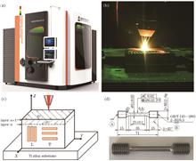
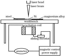
Yi Rong, Donghai Cheng, Zhenyu Xiong, Yiping Chen, and Zhaoze Liu
Objective Universal demands to reduce energy consumption and emissions have elevated the role of lightweight design in the fields of aviation, ship, and automobile. These demands can be satisfied using Mg/steel dissimilar materials welding; however, many problems must be considered when attempting to realize a high-quality connection between Mg alloy and steel. The physical, chemical, and mechanical properties of Mg alloy and Fe are quite different. In addition, they are immiscible, and no intermetallic compounds are produced between Fe and Mg. Currently, to solve this problem, the formation of interfacial compounds is promoted by adding or coating an Ni, Cu, Ag, Zn, Sn, Cu-Zn, and Zn-xAl interlayer. Applying alternating magnetic field during laser welding process mainly brings two effects, including skin effect and electromagnetic force. When an alternating magnetic field is applied, liquid metal will produce an alternating induced current, which has a skin effect. In addition, the magnetic field and induced current produce an electromagnetic force; the alternating electromagnetic force promotes the positive and negative rotation of the molten pool, and convection in the molten pool is intensified. Previous studies have shown that the external alternating magnetic field can improve the weakness of joint compounds in the welding process of Mg/steel dissimilar materials. Ni can form intermetallic compounds and a solid solution with Mg and Fe, respectively. An alternating magnetic field is expected to regulate the distribution of compounds, which will improve the mechanical properties of joints. Therefore, laser welding-brazing technology assisted by alternating magnetic field is adapted to Mg/steel dissimilar materials welding with Ni interlayer. Microstructure and mechanical properties of the joint with and without alternating magnetic field are compared. The Mg/steel dissimilar metal connection with the Ni interlayer technology is further improved by applying an alternating magnetic field, and relevant data support is provided.Methods Experimental materials included AZ31B Mg alloy and Q235 low carbon steel. The dimensions of Mg alloy and steel plates were 120 mm×60 mm×1 mm. A 0.1 mm thick pure Ni foil (99.9%)was used as the interlayer. The dimensions of the Ni foil were 60 mm×10 mm×0.1 mm. A 6 kW fiber laser (IPG YLS-6000CUT) was used for welding, and the laser beam was focused as a spot with a 0 mm diameter on the plates. During welding, the top surface of the plates was protected by argon with 99% purity at a flow of 15 L/min. AZ31B Mg alloy was lapped on Q235 low carbon steel with a clamp, and a 0.1 mm Ni foil was sandwiched between Mg alloy and the Q235 low carbon steel. After welding, the sample was cut along the direction perpendicular to the weld seam using a wire cutting machine, and the inlay was made using an XQ-1 hot mosaic machine and then polished. According to a preliminary test, the optimum welding parameters were P=1250 W, v=20 mm/s; the alternating magnetic field parameters were excitation current, IE=0.8--2.0 A (every 0.2 A is an increasing unit) and excitation frequency, f=15--55 Hz (every 10 Hz is an increasing unit). Scanning electron microscope and energy dispersion spectrometer were used to study the cross-section morphology, Mg side weld zone, steel side weld zone, and intermetallic compound (IMC) layer of the joint under longitudinal alternating magnetic field. A WDW-100 electronic universal tensile testing machine was used to conduct tensile and shear tests on the joint. The tensile rate was 0.5 mm/min. Three groups of samples were stretched with each parameter. The average value of the three groups of parameters was calculated to determine the corresponding tensile and shear strength.Results and Discussion The diffusion and reaction of Mg, Ni, and Fe elements in weld metal were promoted by strong electromagnetic stirring after applying the alternating magnetic field (Figs.3 and 4). The appearce of zonal structures of Fe-Ni solid solution in the weld pool of Mg side weld zone and the serrated Mg2Ni in the brazing zone of the IMC layer enhanced the mechanical bite effect. A continuous nanoscale AlNi layer was formed in the fusion welding zone, and this strengthened the joint (Figs.5 and 6). With increased excitation current IE and excitation frequency f, the tensile and shear strength σb of the joint initially increased and then decreased. For P=1250 W, v=20 mm/s, IE= 1.2 A, and f=35 Hz, the maximum σb of the joint reached 228 MPa, which was approximately 15% higher than that without the magnetic field (Fig.8).Conclusions It is expected that the compound distribution of Mg/steel joints can be controlled by applying an alternating magnetic field, and the mechanical properties of the joints can be improved. The diffusion and reaction of Mg, Ni, and Fe elements in weld metal were promoted via strong electromagnetic stirring after applying the alternating magnetic field. The appearance of zonal structures of the Fe-Ni solid solution in the weld pool of the Mg side weld zone and the serrated Mg2Ni in the brazing zone of the IMC layer enhanced the mechanical bite effect. A continuous nanoscale AlNi layer was formed in the fusion welding zone, and it strengthened the joint. With increased excitation current IE and excitation frequency f, the tensile and shear strength σb of the joint increased initially and then decreased. For P=1250 W, v=20 mm/s, IE=1.2 A, and f=35 Hz, the maximum σb of the joint reached 228 MPa, which is approximately 15% higher than that without the magnetic field.
Oct. 28, 2021Vol. 48 Issue 22 2202005 (2021)
Wentao Qin, Yongqiang Yang, Changwei Weng, and Changjun Han
Objective Directed energy deposition (DED) is a popular additive manufacturing technology that uses a high-energy beam to melt metal powders and deposit them onto a substrate. It has the advantage of printing large-scale metal parts efficiently. Common high-energy sources for DED systems include laser, plasma arc, and electron beam. Laser DED (L-DED) is considered to print parts with better mechanical performance but low printing efficiency compared to plasma arc DED (PA-DED). Furthermore, there is a significant difference in the metallurgical mechanism between the two processes. In this study, we compared the geometry, microstructure, and mechanical properties of 316L stainless steel deposited by L-DED and PA-DED processes. The underlying mechanisms of the difference in geometry, microstructure, and mechanical properties of samples printed by the two processes were discussed.Methods An in-house developed DED system that consists of a fiber laser with a maximum power of 6 kW, two robot arms, one L-DED module, and one PA-DED module was used. A 316L stainless steel powder with a particle size ranging from 60 to 125 μm was adopted as the feedstock for the two printing processes. Single tracks with a length of 80 mm were printed via the two processes, and their cross-sections were etched for geometry measurement. A quadratic regression orthogonal experiment was designed to investigate the effect of energy input, scanning velocity, and powder feeding velocity on the geometry of printed thin walls. The dimensions of the thin walls are 80 mm×3 mm×100 mm. The average layer width and height were measured from the middle location of the thin walls. The L-DED process parameters included a laser power of 2000 W, a scanning speed of 10 mm/s, and a powder feed rate of 24 g/min. The PA-DED process parameters included a current of 30 A, a scanning speed of 5 mm/s, and a powder feed rate of 12 g/min. Samples perpendicular to the build direction, parallel to the build direction, and inclined at 45° were machined for tensile testing. Microstructures of the printed thin walls were also observed from their cross-section locations.Results and Discussions The average powder utilization rate of the two printing processes was calculated by measuring the weight difference before and after the deposition (Table 4). The average powder utilization rates of L-DED and PA-DED were 35.9% and 72.9%, respectively. The twice powder utilization rate of PA-DED compared with L-DED was attributed to the high-velocity of plasma arc that could accelerate powder particles deposited into melt pools during printing. The cross-sectional morphologies of the single tracks indicated that L-DED enabled a better metallurgical bonding between the melt pool and substrate than the PA-DED process. This was ascribed to the higher energy density of L-DED, increasing the penetration of the melt pool. The entire process was similar to deep penetration welding. In contrast, the small current used in PA-DED led to slight melting of the substrate surface, where the process was similar to conduction welding with a shallow melt pool. Therefore, a preheating process for the substrate or the utilization of a high current for the first printing layer should be conducted in the PA-DED process to enhance the bonding. The regression equations of layer width and height for PA-DED and L-DED were realized. The variance analysis of orthogonal experimental results (Tables 6 and 7) indicated that the process parameters of PA-DED and L-DED exhibited different influence orders on layer geometry. In the PA-DED process, the process parameters that influenced the layer width by the descending order were current, powder feed rate, and scanning speed, whereas the parameters that influenced the layer height by the descending order were powder feed rate, current, and scanning speed. Comparatively, in L-DED, the process parameters that influenced the layer width by the descending order were scanning speed, powder feed rate, and laser power, whereas the parameters that influenced the layer height by the descending order were powder feed rate, scanning speed, and laser power. The influence trend of process parameters on the geometry of the two processes was consistent when only a single factor was considered. As the energy input increased, the floor width increased and the floor height decreased; the layer width and height increased with an increase in the powder feeding quantity and decreased with an increase in the scanning speed. The microstructure morphologies (Fig. 5) of samples printed by the two processes were slightly different. PA-DED samples were dominated by directional growth long columnar grains with sizes up to millimeters, and many secondary dendrites could be obtained. However, L-DED samples showed shorter columnar grains and various growth directions in different regions. Particularly, the grains grew mainly perpendicular to the melt pool boundary. Tensile and microhardness testing results (Fig.6 and Fig.7) showed that samples fabricated by PA-DED achieved comparable mechanical properties to those printed by L-DED. The tensile strength of the samples was 593 and 570 MPa for L-DED and PA-DED, respectively.Conclusions The powder utilization rate of PA-DED was significantly higher than that of L-DED. However, the dilution rate of the first layer of PA-DED was low on the substrate without preheating, leading to insufficient interfacial bonding strength. The prediction equations of the layer width and height of 316L thin-walled parts by L-DED were established. The effects of process parameters on the geometry of the two printing processes were compared. Current had a great influence on the layer width and height during PA-DED, whereas the influence of laser power on the layer width and height during L-DED could not be compared with the powder feed rate and scanning speed. The microstructure of PA-DED samples tended to grow directionally and their columnar grains were longer. L-DED samples obtained smaller columnar grains, which possessed various growth directions in different regions.
Oct. 28, 2021Vol. 48 Issue 22 2202006 (2021)
Yanhu Zhang, Faquan Tang, Xiaoling Gu, and Hao Fu
Objective High-speed laser cleaning mainly uses two independent and controlled orthogonal motors to realize the spiral filling and ablation in a two-dimensional area. A galvanometer motor is used as the positioning motor. In the fixed trajectory mode, the ablation points of spiral filling are distributed in a network. The intersection points of the network are overlapped and ablated, and there are non-ablated grid gaps. In the laser-cleaning process, the scanning speed of an edge area is slower than that of a centre area, the thermal action time becomes longer and the ablation is too heavy. The above mentioned problems can easily lead to two aspects of undesired results. First, the laser-cleaning surface left marks and large format edge area exhibits severe overlap ablation, even high-power laser-cleaning edge cutting phenomenon. Second, repeated and excessive ablation in the local area for a long time causes severe heat accumulation, easily damaging the substrate. Therefore, this study aims to solve the abovementioned problems during the laser-cleaning process.Methods The double-motors spiral-scanning mode was adopted to separate the motor drive board from the cleaning gun head. A random yaw factor was used to regulate the noise voltage introduced by the wire group between the motor driving plate and the cleaning gun head. The introduced factor was adjusted to make the galvanometer motor spiral and yawed randomly to ensure that each coordinate position in the plane was unique and not repeated, which greatly reduced the probability of excessive ablation. In the edge area, the simple opening and closing method of controlling the laser was changed. Then, the laser energy was controlled in the edge area by modulating the laser frequency, reducing the degree of accumulation of thermal effects. Therefore, separating the machine and card of the galvanometer motor and introducing a random factor into the spiral-cleaning path was designed for achieving more uniform cleaning effect and more stable control system and thermal environment.Results and Discussions The uniformity problem and excessive edge ablation are destructive for the two-dimensional laser cleaning. Aiming at a series of problems exposed by the traditional progressive ablation-cleaning method, a random spiral-filling path is designed to control the independent movement of X/Y motors (Fig.4). The initial angles of the two motors differ when setting the swing, i.e., the initial phases are different. Dual motors swing at full speed according to the designed trajectory, and the dynamic phase difference forms a network distribution to fill the entire surface area (Fig.5). The scanning speed of the galvanometer in the non-edge area is the combined speed of the two motors due to their independent movement, and the cleaning efficiency is improved. A certain motor is always maintained in the edge area to reduce the dwell time of the laser in the non-edge area (Fig.6) and weaken the edge over-burning. Similar to progressive ablation, there are still gaps in the mesh distribution under fixed trajectory scanning, which can be controlled by adjusting the subdivision degree of phase difference. For a large mesh gap (larger than the laser spot), there are still gullies between the gaps after the ablation process (Fig.8). By introducing a random yaw factor (Fig.7), the position of the motor is not required to be fixed each time when scanning back and forth, thereby avoiding the formation of a fixed net-like distribution. the removal amount is uniform under random scanning and the removal amount of fixed trajectory scanning is unevenly distributed (Fig.9). Uniform cleaning is difficult to achieve via regular spiral scanning. It is more likely to produce cracks in the transition zone and cause damage to the substrate. Under the random spiral trajectory, the probability of the occurrence of sample’s subsurface cracks is reduced (Fig.10).Conclusions The two motors are linked to fill a two-dimensional area during the scanning process of a high-speed laser-cleaning system using a spiral path. The scanning efficiency is improved compared with that in the case of using only a single motor during line-by-line cleaning. However, spiral filling appears at a mesh-crossing position and repeated ablation occurs. Although line-by-line cleaning has no ablation and intersection area, the cleaning efficiency is low. When the area overlaps, the spiral or progressive scanning has the problem of excessive area overlap and ablation, resulting in area overlap marks during laser cleaning. Therefore, this study separates the motor drive board from the cleaning head and actively introduces the random superimposed noise factor into the control system to improve laser-cleaning efficiency. The random yaw factor is introduced into the cleaning path planning of the galvanometer spiral surface filling, which helps to prevent repeated ablation with the reticular cross for the fixed track scanning. Meanwhile, the laser frequency is modulated in the scanning period to reduce the laser energy near the cleaning edge and avoid excessive ablation during the motor deceleration process. The results show that the random spiral scanning in the non-edge region is useful for making the random distribution of laser ablation points and avoiding repeated ablation at a single point during laser cleaning. The laser scanning speed at the edge is slowed down, and the ablation energy is reduced. Thus, considerably reducing the probability of crack formations in the transition zone of the substrate. Therefore, the cleaning system with position modulation of the laser frequency under the spiral random scanning mode can effectively address the problem of uneven distribution of laser ablation degree and vulnerability of substrate after cleaning.
Oct. 28, 2021Vol. 48 Issue 22 2202007 (2021)
Gaolei Zhang, Hua Kong, Jianglin Zou, Zhenjia Zhao, and Rongshi Xiao
Objective Because of its high power, flexibility, compact size, and low operating cost, high-power fibre lasers have sparked widespread interest in laser welding. However, because of the high energy density of high power fibre lasers, producing a large number of spatter particles during welding is easy, which has a serious negative impact on welding. On the one hand, spatters will pollute the focusing mirror or be located in the laser beam transmission path, resulting in a change in the focusing characteristics of the laser beam and a loss of laser energy transmission, which will seriously affect the welding process’s stability; on the other hand, spatters will cause weld metal loss, resulting in welding defects such as depression and incomplete weld. As a result, studying spatter generation is crucial for understanding the physical process of high power fibre laser welding and optimising welding technology.Methods In this paper, a high-speed camera was used to observe the formation of spatters and the fluctuation behaviour of the molten pool during high-power fibre laser welding. The dimension and quantity of spatter were measured after welding using a scanning electron microscope, and the plate mass loss before and after welding was calculated. The power density of the fibre laser was altered by adjusting the defocus, and the number of spatters and plate mass loss were investigated. Finally, the effect of defocus on mass loss and spatter formation is investigated using the experimental results.Results and Discussions The formation of typical spatter particles in fibre laser deep penetration welding was observed using a high-speed camera (Fig.2). The spatter particles collected from the glass cylinder after welding were measured using a scanning electron microscope. The results show that the spatter particles were mostly distributed in the >50--100 μm range (Fig.3). The relationship between plate mass loss and spatter number was then established, and the variation of spatter number and plate mass loss with defocus was demonstrated (Fig.6). Finally, the spatter was related to the inclination angle of the front keyhole wall, the laser-induced vapour on the front keyhole wall, and the surface tension of the molten pool; the reason why the number of spatters increased with defocus was summarised.Conclusions The spatter behaviour and effect of defocus in high power fibre laser deep penetration welding are investigated in this paper through in-situ optical observation of the molten pool and measurement of plate mass loss. The results show that the formation of spatter in fibre laser molten pool can be divided into three steps: molten pool bulges on the edge of keyhole→ the bulge is elongated to form a liquid column→ the liquid column breaks up to overcome the surface tension and form spatter particles. The spatter particles are mainly distributed between 50 and 100 μm. With the increase in laser defocus, the spatter number, plate mass loss and weld width gradually increase, whereas the penetration gradually decreases. Further investigation reveals that the eruption of spatters is related to the inclination angle of the front keyhole wall, impact force of laser-induced evaporation of the front keyhole wall, and molten pool surface tension. Increasing the defocus reduces the inclination angle of the front keyhole wall and the surface tension of the molten pool, which increases the impact force of the evaporation vapour from the front wall to the upper edge of the rear keyhole wall, resulting in more spatters.
Oct. 28, 2021Vol. 48 Issue 22 2202008 (2021)
Lairong Xiao, Wei Tan, Liming Liu, Xiaoxuan Tu, Zhenwu Peng, Huan Wang, and Xiaojun Zhao
Objective In recent years, additive manufacturing of GH3536 alloy has made it an appealing nickel-base superalloy for aircraft engine applications. At the moment, much attention is being paid to the as-deposited alloy, with particular emphasis on the forming process, microstructure, and tensile properties. However, there are only a few reports on low cycle fatigue properties in the open literature. The anisotropic fatigue properties of as-deposited alloys have been demonstrated. Furthermore, the as-deposited alloy’s flaws will considerably reduce its fatigue lifetime. Fortunately, hot isostatic pressing (HIP) and solution treatment (ST) are viable methods for improving the alloy’s fatigue properties. The goal of this study is to evaluate the low cycle fatigue properties of GH3536 alloy treated with HIP and ST at room temperature and 800 ℃, as well as to identify the deformation and fracture mechanisms. In addition, a plastic strain energy model for predicting fatigue lifetime is developed.Methods GH3536 alloy was prepared using Farsoon FS 271m selective laser melting equipment with argon gas protection. The HIP was performed in QIH-62 equipment for 3 h at 1175 ℃ under a pressure of 160 MPa in a vacuum environment, after which the alloy was furnace-cooled to room temperature. ST was performed in SX-12-16 equipment at 1175 ℃ in a vacuum environment for 2 h, followed by argon cooling. Low cycle fatigue specimens were processed according to GB/T 15248—2008 and tested on MTS 810 fatigue testing machine at room temperature and 800 ℃ under strain control. The loading waveform was a triangular wave; the total strain amplitude was 0.25%--1.2%; the strain rate was 0.01 s -1, and the strain ratio was -1. The TESCAN MIRA3 scanning electron microscopy was used to examine the fracture morphology of the fatigue specimens, and the Tecnai G2 20 transmission electron microscope was used to examine the microstructure after the fatigue test. Results and Discussions Temperature and strain amplitude appear to have an impact on fatigue life and cyclic deformation behavior. The fatigue life of the alloy at room temperature is greater than that at 800 ℃. At room temperature, the alloy exhibits cyclic hardening before cyclic softening. However, at 800 ℃, the specimens with 0.25% and 0.4% strain amplitudes show cyclic hardening at first, cyclic stabilization subsequently, and then cyclic softening until the final rupture. After cyclic hardening, the specimens with 0.8% and 1.2% strain amplitudes only show softening (Fig. 3). The Basquin-Coffin-Manson model accurately describes the relationship between total strain amplitude, elastic strain amplitude, plastic strain amplitude, and fatigue cycles. The transition fatigue life at room temperature and 800 ℃ calculated using the Basquin-Coffin-Manson model is 12399 and 1152 cycles, respectively (Fig. 6). At room temperature, the fracture morphology exhibits a single fatigue source that originates from the resident slip band near the surface of the specimen (Fig. 7). Whereas, at 800 ℃, multicrack sources usually derived from defects near the surface can be observed (Fig. 8). The increase in dislocation density at room temperature makes dislocation slip more difficult and increases the alloy’s cyclic hardening degree (Fig. 9). As a result of dynamic recovery, the density of dislocations at 800 ℃ is lower than that at room temperature. High temperature and dislocations promote the heterogeneous nucleation of precipitates. Therefore, the interaction between precipitates and dislocations results in cyclic hardening of the alloy (Fig. 10). The plastic strain energy model is used to predict the life of the alloy. The intrinsic fatigue toughness (W0) and fatigue transition exponent (β) are 222.24 MJ/m 3 and 2.320 at room temperature and 673.15 MJ/m 3 and 1.225 at 800 ℃, respectively. The predicted lifetime is within 1.5 times of the dispersion band (Fig. 11). Conclusions The fatigue lifetime of GH3536 alloy treated with HIP and ST decreases as temperature or strain amplitude increases. At room temperature, the alloy undergoes cyclic hardening before cyclic softening at various strain amplitudes, and its fatigue crack source is a single one. The increase of the dislocation density is an important factor of cyclic hardening. However, at 800 ℃, the alloy initially exhibites cyclic hardening, then cyclic stabilization, and finally cyclic softening to failure at low strain amplitude. Meanwhile, at high strain amplitudes, the alloy exhibits cyclic softening after cyclic hardening. Furthermore, on the fracture surface of the fatigue alloy tested at 800 ℃, a number of crack sources are observed. The alloy hardens due to the pinning effect of the precipitated phases. The alloy’s fatigue lifetime and strain amplitude satisfy the Basquin-Coffin-Manson equation, and the transition fatigue lifetime at room temperature and 800 ℃ is 12399 and 1152 cycles, respectively. The plastic strain energy model accurately predicts fatigue life, and the predicted results are within 1.5 times of the dispersion band.
Nov. 02, 2021Vol. 48 Issue 22 2202009 (2021)
Hongyu Zhang, Min Yu, Junwei Hua, and Hui Chen
Objective Wear is one of the common failure modes of mechanical parts, and the preparation of anti-friction and wear-resistant coatings on the surfaces of parts susceptible to wear is an effective method to relieve wear. Molybdenum (Mo) is considered one of the best materials in achieving high resistance to wear. Although thermal sprayed Mo coating has excellent wear resistance and self-lubricating properties, the mechanical bond between thermal spray coating and substrates is difficult to meet the strength requirements of some key components. Due to its metallurgical bonding feature, laser cladding has received considerable attention in recent years. For steel substrates, iron-based, cobalt-based, and nickel-based self-fluxing alloy powders are the most commonly used cladding materials. A small amount of Mo element (mass fraction Methods Pure Mo powder was mixed with Fe-Cr powder using a YXQM-2L planetary ball mill, and five kinds of cladding powders (Fe-Cr, Fe-Cr+10%Mo, Fe-Cr+30%Mo, Fe-Cr+50% Mo, and Fe-Cr+70%Mo) were obtained. Multi-channel cladding layers with different Mo contents were prepared on the EA4T steel by laser cladding using a Nd∶YAG IPG-4000 solid-state fiber laser. The phase and microstructure of the coating were characterized by X-ray diffractometer (XRD), optical microscope (OM), scanning electron microscope (SEM), and energy dispersive spectrometer (EDS). The mechanical properties of the coating were tested by the microhardness and the micro-shear tests. The wear-resisting property of the coating was tested by the friction and wear test.Results and Discussions According to the XRD and EDS results of the coating (Fig.5, Table 5 and Table 6), the main phases of the Fe-Cr coating are the solid solution of Cr in α-Fe and the σ phase. When the mass fraction of Mo in cladding powder is 10%, Mo in the coating is mainly in the form of an intermetallic compound Mo5Cr6Fe18. When the mass fraction of Mo is 30%, there are some Mo5Cr6Fe18 and FeMo at the grain boundaries of the coating and few Mo atoms are dissolved in the crystal. The Mo content in the grains of the Fe-Cr+50%Mo coating is higher than that at the grain boundaries. There are more Mo simple substance phases in the coating and there are Mo5Cr6Fe18 and FeMo phases at the grain boundaries. When the mass fraction of Mo in cladding powder is 70%, more Mo atoms are dissolved in α-Fe, and more Mo5Cr6Fe18 and FeMo are formed at the grain boundaries. However, Fe-Cr+70%Mo coating cracks during cladding, so the performance of the Fe-Cr+70%Mo coating will not be discussed in the following. The hardness of the Fe-Cr cladding layer, Fe-Cr+10%Mo cladding layer, Fe-Cr+30%Mo cladding layer, and Fe-Cr+50%Mo cladding layer is higher than that of the substrate, and the addition of Mo reduces the hardness of the coating and the hardness gradient from the coating to the substrate (Fig.6). The micro-shear test results show that all coatings have higher strength and lower toughness and plasticity than other areas, and the toughness and plasticity of the coating first decrease and then increase with an increase in Mo content (Figs. 7 and 8). The results of the friction and wear test show that the four coatings can effectively reduce wear. Among them, the Fe-Cr coating has the lowest amount of wear, but its friction coefficient is higher than that of the substrate. The coefficient of friction of the coatings with Mo addition is lower than that of the substrate, and the coefficient of friction decreases with an increase in Mo content (Fig.12). The reason is that the addition of Mo reduces the hardness of the coating, and the oxide of Mo generated during friction exists in the surface and wear debris, which has a lubricating effect. According to the wear morphology, with an increase in Mo content, the wear form gradually changes from abrasive wear to adhesive wear (Fig.13).Conclusions In this study, Fe-Cr cladding layer, Fe-Cr+10%Mo cladding layer, Fe-Cr+30%Mo cladding layer, and Fe-Cr+50%Mo cladding layer prepared under the selected laser cladding parameters are well formed, uniform, dense, and have good bonding performance with the substrate, where Fe-Cr+70%Mo cladding layer cracked. When the mass fractions of Mo in cladding powder are 10% and 30%, Mo in the coating mainly forms intermetallic compounds with Fe-Cr. When the mass fraction of Mo in cladding powder exceeds 50%, several Mo simple substances begin to appear in the coating. The hardness and shear strength of Fe-Cr cladding layer, Fe-Cr+10%Mo cladding layer, Fe-Cr+30%Mo cladding layer, and Fe-Cr+50%Mo cladding layer are higher than those of the substrate, and the addition of Mo reduces the hardness of the coating. Fe-Cr cladding layer, Fe-Cr+10%Mo cladding layer, Fe-Cr+30%Mo cladding layer, and Fe-Cr+50%Mo cladding layer can effectively reduce wear, but the friction coefficient of Fe-Cr cladding layer is higher than that of the substrate, and the friction coefficient of Mo-doped cladding layer is lower than it. Besides, the friction coefficient of the coating decreases with an increase in Mo content, and the wear form changes from abrasive wear to adhesive wear gradually. The Fe-Cr+50%Mo cladding layer has the best anti-friction and wear resistance, and the coefficient of friction in the test is 0.66.
Nov. 05, 2021Vol. 48 Issue 22 2202010 (2021)
Guowei Yang, Nan Zhou, Min Yang, Yongshuai Zhang, and Yizhong Wang
Objective Weld tracking based on laser vision is widely used in automatic welding due to its noncontact, high precision, and other advantages. It is critical to obtain precise key position information such as the weld’s centerline, width, and groove edge. However, in the field, there will be welds with different groove forms, and the weld images will be disturbed to varying degrees by noise such as arc light, splash, and smoke. The traditional image processing methods cannot fully adapt to weld tracking in various complex environments. To overcome the noise interference in a complex welding environment and improve the accuracy and adaptability of weld tracking, a feature point extraction network based on a convolution neural network to locate weld feature points is proposed. To ensure accuracy and robustness, the network makes full use of its strong learning ability. It is not necessary to use the proposed convolution neural network to extract weld feature points in each weld image to improve welding efficiency in actual welding. The stable and predictable change of weld position can be used for weld tracking. Therefore, a reliable and fast automatic weld tracking can be realized by using the network to locate the feature point and fusing a kernel correlation filter (KCF) algorithm.Methods To overcome noise interferences and accurately locate the groove edge of the weld, a weld feature point extraction network with the powerful feature extraction ability and learning ability of the convolution network is proposed. The network’s convolution and pooling operations can extract the position and edge contour of the laser line in the weld image. A prior region generation module is used in the network to divide the input weld image into several prior regions. It transfers the key position detection of the weld from the entire welding image to the prior regions, reducing the difficulty of extracting the weld’s key positions and improving positioning accuracy. The recognition and location module in the network can combine the prediction of the position with the prediction of the confidence of the feature point, which effectively suppresses the interference of noise and improves the anti-interference ability of the network. The training weld data set is expanded to include multiple groove weld types, which improves the network’s generalization ability and adaptability to different groove weld types. To track the weld feature points and improve welding efficiency in actual welding, the proposed network and a KCF are fused. Because the shape and position of the laser line of the weld image of adjacent frames change little, which is stable and predictable, the cyclic shift method is used in the KCF to obtain enough training samples to ensure weld tracking accuracy. Simultaneously, the fast Fourier transform is used to reduce the time complexity of the algorithm, ensuring weld tracking speed.Results and Discussions The location results of feature points that were interfered by noises such as smoke and splash demonstrate that the weld feature point extraction network has a strong anti-interference ability (Fig.4). The weld feature points are located more accurately because the network combines the predictions of the position and confidence, which can suppress the noise interference. The location results of feature points lying in various groove types demonstrate that the network has strong adaptability and generalization ability in actual welding scenes (Fig.5). The training data set contains a variety of weld groove types, which improves the network’s robustness and generalization. Therefore, the network learns the welding characteristics of different groove types to improve adaptability. The tracking results under various noise interferences demonstrate that the proposed method can improve weld tracking accuracy (Fig.6). Furthermore, tracking results for various groove types show that the proposed method in this paper is widely applicable to multigroove welds with good generalization (Fig.8).Conclusions In this paper, an automatic weld tracking method that combines a convolutional neural network and a correlation filter are proposed. Various degrees of noise interference during welding pose significant challenges to the accurate positioning of weld feature points. The prior region generation module in the network transfers the feature point location to the prior region, which ensures the accuracy of the feature point location. The network’s identification and location module combine position prediction and confidence prediction to suppress noise interference and improve the network’s anti-interference ability. The proposed method overcomes noise interference in complex welding environments and avoids feature point misjudgment. The fusion of a correlation filter and a network enables the automatic tracking of weld feature points. Furthermore, the correlation filter employs a fast Fourier transform to reduce the time complexity of the algorithm, ensuring welding speed. In addition, for different groove types of welds, this method which has strong adaptability can locate feature points more accurately. To summarize, the proposed method has a certain anti-interference and generalization ability that meets the actual welding requirements.
Oct. 28, 2021Vol. 48 Issue 22 2202011 (2021)
Qiang Wu, Renjie Jiang, Xingtong Li, Jiangling Zou, and Rongshi Xiao
Objective 2060 aluminum-lithium alloy is a third-generation aluminum-lithium alloy, which has excellent performance, such as low density and high specific stiffness. It has broad application prospects in the aerospace field. Fiber laser welding technology is rapidly developing because of high welding speed and high efficiency. The lightweight material of the aluminum-lithium alloy, combined with fiber laser welding, can satisfy the lightweight requirements of aircraft. Because of the large thermal expansion coefficient of the aluminum-lithium alloy and easy burning of elements, the problems of cracks, pores, and mechanical properties are concerning. Although the crack-assisted process can effectively suppress cracks, the pores and mechanical properties still need to be improved. Moreover, the filler wire welding process causes problems such as high light wire matching and complicated melting and solidification behavior of the wire. In this study, focus rotation and filler wire were adopted in the fiber laser welding (denoted as laser welding-FRFW) of 2 mm-thick 2060 aluminum-lithium alloy to analyze the impact of laser focus rotation on the weld formation, porosity, distribution of microstructures in the weld, and the mechanical properties of the welded joint.Methods The test specimen was a piece of 2060-T8 aluminum-lithium alloy. We used 4047 welding wires with a diameter of 1.2 mm. The YLS-6000 fiber laser was used. The core diameter of the transmission fiber was 200 μm, the focal length of the collimating lens was 200 mm, and the focal length of the focus lens was 300 mm. The wedge angle of the wedge prism was designed to obtain the required laser focus rotation radius. A laser focus rotating device was used to regulate the rotational speed of the wedge prism. We adopted the process parameters as follows: laser power, 3.8 kW; welding speed, 3 m/min; wire-feeding angle, 45°; wire-feeding speed, 3 m/min; laser-wire distance, 0 mm. Furthermore, a color high-speed camera was used to observe the droplet transfer behavior in the welding process. When the welding was completed, we prepared metallographic specimens for analyzing the weld morphologies and porosity. Scanning electron microscopy was used to observe the microstructures of welded joints. A scanning electron microscope and an energy dispersive spectrometer (EDS) were used to analyze the ingredients of any selected area. Further, X-ray diffraction (XRD) was used to analyze phase compositions in different areas within the weld. We used a hardness tester to measure the microhardness of the welded joints with the load of 0.98 N loaded for 15 s. The tensile properties of welds were tested based on the ASTM E8m standard.Results and Discussions The weld morphology considerably changed after applying laser welding-FRFW (Fig. 1). The surface of the weld was smooth with shallower fish scale-shaped ripples; the width of the entire weld became more uniform; and the spatters around the weld were effectively suppressed. The laser focus periodically acted on the weld pool and the end of the welding wire, and the weld pool was stable with a small fluctuation range and no spatter (Fig. 3 and Fig. 4), and there were only tiny pores around the fusion line (Fig. 5). The laser focus periodically acted on the welding wire and weld pool. This action can make the weld pool longer, making it easier for bubbles to move upwards and escape the weld pool.There were four zones distributed from the fusion line to the center of the weld: HAZ, PMZ, EQZ, and CGZ (Fig. 6). When focus rotation was applied, the obvious thick grain boundary could still be observed in the PMZ near the fusion line. Further, the width of the EQZ was reduced, and the sizes of column grains near the equiaxed grain zone became smaller [Fig. 7(a) and Fig. 7(b)]. The main precipitated phases are α (Al) solid solution, θ phase (Al2Cu), and T phase (AlLiSi).The low hardness appeared in the PMZ in both cases(Fig. 13). In filter wire laser welding, the strength at the weld center was reduced to approximately 115 HV0.1. When focus rotation was applied, the strength of the entire welded became more uniform and increased to approximately 123 HV0.1. Compared with that of the filler wire laser welding without focus rotation, the microhardness of the welded joint prepared by filler wire laser welding with focus rotation was increased by 6.9%. According to the tensile test results (Fig. 14), the tensile strength of the welded joint of laser welding-FRFW was 365.0 MPa, which is slightly higher than 349.4 MPa (the joint of filter wire laser welding). Fracture of each welded joint occurred in the area near the fusion line of the welds. Fractures of the welded joints obtained in both welding processes were dimple-aggregation type intergranular fractures with features of mixed fractures.Conclusions Because of the high-frequency rotation of the laser focus, the laser focus could act periodically on the weld pool and one end of the welding wire. Based on the laser welding-FRFW, the weld pool was longer and more stable, which can improve the weld morphology, suppress spatters and reduce the number of pores. The width of the EQZ and sizes of the grains in EQZ as well as the sizes of the columnar grains near the equiaxed grain zone on the weld were reduced in the laser welding-FRFW. The microhardness near the fusion line and tensile strength of the welded joint were slightly increased compared with the filter wire laser welding without focus rotation. Moreover, the fracture of the welded joint, with features of mixed fractures, occurred near the fusion line.
Oct. 28, 2021Vol. 48 Issue 22 2202012 (2021)
Renjie Jiang, Zhiwei Cheng, Qiang Wu, and Rongshi Xiao
Objective Pure aluminum and pure copper have excellent electrical and thermal conductivities and corrosion resistance, and are widely used in aerospace, heat exchange equipment, electronic products and batteries. The density and cost of copper and aluminum are quite different. In order to give full play to the physical characteristics of these two materials and reduce the cost of components, the aluminum/copper composite structure has emerged as a great application requirement in the industrial field. How to achieve reliable welding of aluminum and copper is the key to the reliable application of aluminum and copper composite structures. This paper proposes a new method for laser brazing-fusion process based on the wire deep penetration mode, and conducts the welding process test and the analysis of the joint structure and performance.Methods Laser wire filler brazing-fusion was performed for 3 mm thick aluminum/copper dissimilar metals, and the influences of groove size, process parameters and the height of the intersection of laser beam and wire from the base material were studied. Cleaning and mechanical grinding are needed to remove the oxide film before welding. Before welding, the 1060 aluminum alloy was first cleaned with the 20%(mass fraction) NaOH solution at 50--60 ℃ for 5 min to remove the surface oxide film. Then it was soaked in the 30% (volume fraction)HNO3 solution for 5 min to neutralize the residual alkali. Finally, the aluminum alloy surface was rinsed with clean water, dried with compressed air, and stored in a sealed bag to avoid contact with air. T2 copper was pickled with the 30% (volume fraction) H2SO4 solution for 5 min, and the surface was washed with clean water to ensure that there was no acid residue on the surface. It was dried with compressed air and stored in a sealed bag. After chemical cleaning, the welding test shall be conducted within 12 h, otherwise the chemical cleaning of oxide film shall be conducted again. The aluminum alloy and pure copper plates with preset groove shall be assembled according to the zero gap butt joint method, horizontally placed on the surface of the worktable, and fixed with clamping tooling, so as to ensure that the assembly gap does not change during welding. High speed camera was used to observe and record the welding process. The high-speed camera was positioned at the welding pool, and the auxiliary light source was placed on the other side to irradiate the welding wire and pool. The CCD imaging system of the camera was used to transmit the image signal to the connected computer for real-time observation and recording. After the welding was completed, metallographic sample was prepared, and the sample was ground and polished. Then, the microstructure of the weld was observed with optical microscope and scanning electron microscope, and the joint performance was tested with universal tensile testing machine and microhardness tester.Results and Discussions Choosing a reasonable groove form can help reduce welding defects such as undercuts and sidewalls that are not fused, and improve the quality of weld formation. The shape and size of the groove are optimized, and the position of the laser in the groove is changed. When the laser beam is biased to the copper side, the laser energy will melt the welding wire and at the same time act on the copper side base material, which has a stronger preheating effect (Table 3). When the height of the intersection of laser beam and wire from the base material is 0, the top view of the weld is continuous and uniform, and the back view of the weld is completely penetrated. According to the observation of high-speed camera, the droplet transition is in the form of liquid bridge. And there is a bolling front in the front of the welding wire. This shows that when the laser beam with an enough high power density irradiates on the welding wire, the melting front will be formed. At this time, the welding wire absorbs the laser energy in a deep penetration mode (Table 4). Scanning electron microscope observation results show that the joint can be divided into aluminum side melting zone, weld zone, and copper side brazing zone. The brazing area at the copper side can be finely divided into the interface layer, the eutectic zone, and the weld zone (Fig. 2). The interface layer is mainly composed of Al2Cu intermetallic compounds, and a few Al4Cu9 phases are also generated (Fig. 4). The hardness distribution in the center of the weld is uniform, and the hardness of the interface layer is up to 296 HV (Fig.5). The average tensile strength of the joint with grinding is about 80 MPa. In contrast, the tensile strength of the joint without grinding is about 60 MPa (Fig. 6). The fracture surfaces of the two kinds of fractures are flat with tearing edges and typical river-like patterns, which can be judged as brittle fractures (Fig. 7).Conclusions The aluminum/copper laser brazing-fusion process based on the wire deep penetration mode was used to obtain a well-formed joint, the tensile strength can reach 80% of that of the aluminum base metal, the fracture of the joint occurs in the interface layer which can be judged as brittle fractures. The groove form and size have significant influence on the weld formation and joint quality. When the laser is biased to the copper side, it can produce a better preheating effect on the copper matrix, which is conducive to the infiltration and spreading of the weld pool, improve the weld forming, and inhibit the undercut defect of the base metal on the copper side. The brazing area on the copper side is subdivided into three areas: the interface layer, the eutectic area, and the weld area. The thickness of the upper interface layer is about 50 μm, and the thicknesses of the middle and lower interface layers are about 20 μm. The interface layer is mainly composed of Al2Cu and Al4Cu9 phases.
Oct. 19, 2021Vol. 48 Issue 22 2202013 (2021)
Penghui Zhao, Jing Feng, Linzhuang Xing, Dong Li, Bin Chen, and Dingying Liao
Objective At present, laser-induced optical breakdown has been widely used in biological sample detection, manipulation, laser-induced breakdown spectra and laser processing of transparent media (glass, etc.). Using the local plasma resonance effect of gold nanoparticles, the laser-induced optical breakdown effect can be enhanced by gold nanoparticles. Under the laser irradiation with strong pulse energy, the morphology of gold nanoparticles may gradually change into irregular spheres with sharp angles and convex edges, leading to significant changes in their photothermal conversion abilities. From the microscopic point of view, it is of great guiding significance to reveal the photothermal conversion rule inside gold nanoparticles in the process of nanosecond or femtosecond laser irradiation and to explore the mechanism of the morphology change of gold nanoparticles under the action of two kinds of lasers. In this paper, a theoretical model of high intensity pulsed laser irradiation of gold nanorods is constructed to study the effects of laser energy density and pulse duration on the photothermal conversion process. Combined with the experimental study of laser irradiation of gold nanorods, the difference in the microscopic melting characteristics of gold nanorods under nanosecond or femtosecond laser irradiation is analyzed.Methods In this paper, the electron-phonon dual temperature model under the action of laser is used to simulate the heating process of gold nanorods in water by intense laser pulses. Firstly, the basic properties of each domain are strictly defined, including the initial temperatures of gold nanorods and surrounding environment and the selection of boundary conditions for the surrounding water. The electron and lattice temperature variations are obtained by solving the governing equations based on the two-temperature model. According to the solved values of electron and lattice temperatures, we can use the energy conservation equation of water to obtain the transient changes of water temperature along the R and Z axes. By changing the pulse duration time and energy density of the laser, we can calculate the changes in lattice temperature and water temperature of the gold nanorods to compare with the experimental results.Results and Discussions After the femtosecond laser irradiation, the free electrons in the gold nano-rods first absorb the laser energy, leading to the temperature rise of electrons. After electron-lattice relaxation, the electrons transfer heat to the lattice. Because the laser action time is short, the lattice and electrons do not reach a thermal balance, so the electron temperature is much higher than the lattice temperature. In addition, the energy has not been transferred to the surrounding environment, so the surrounding water temperature is significantly lower than that of the gold nano-rods. The pulse duration is significantly prolonged under the nanosecond laser irradiation, the temperature difference between the lattices and the free electrons in gold nanorods is significantly reduced compared with that under femtosecond laser irradiation, and the surrounding water temperature is significantly increased.Comparing gold nanorods irradiated by nanosecond laser and those irradiated by femtosecond laser, we can find that when the gold nanorods are irradiated by 0.001 J/cm2 femtosecond laser, the gold nanorods will be melt, but at the moment, the temperature of gold nanorods around the water is far lower than the melt temperature of the gold nanorods, and the temperature difference between gold nanorods and water is as high as 1100 K. Such a large temperature difference results in that the surface and interior of the gold nanorods cannot change in thermal expansion volume at the same time. The huge internal stress is formed due to the different volume change of each part. As a result, the gold nanorod is prone to produce point defects and line defects from the inside, and these defects subsequently evolve into plane defects and then nanorods fracture. When the 0.1 J/cm2 nanosecond laser is applied to the gold nanorod and makes it melt above threshold, the gold nanorod melt temperature, the water temperature around the interface of gold nanorods and the water temperature are 550 K, far below the femtosecond laser heating threshold. The gold nanorod surface thermal stress is significantly reduced and the gold nanorods are not easily broken.Conclusions In this paper, the theoretical and experimental studies are carried out to analyze the photothermal conversion inside gold nanoparticles and the influence on environmental media during laser irradiation from the microscopic point of view. The results show that the changes in electron and lattice temperatures under nanosecond laser irradiation are basically the same as those under femtosecond laser irradiation. However, compared with those under femtosecond laser irradiation, the temperature difference between the lattices and the free electrons in the gold nanorods is significantly reduced and the surrounding water temperature is significantly increased due to the significantly long pulse duration under nanosecond laser irradiation. Since the high peak power is favorable for the formation of defects on the crystal surface, the melting threshold of gold nanorods under femtosecond laser irradiation (about 0.001 J/cm2) is 99% lower than that under nanosecond laser irradiation (about 0.1 J/cm2). By comparing the experimental results under femtosecond and nanosecond laser irradiations on gold nanoparticles, the difference in the photothermal conversion characteristics of gold nanoparticles under different pulsed laser irradiations are further analyzed. The results show that when the temperature of the gold nanorods reaches the threshold, the shape of the gold nanorods changes under femtosecond laser irradiation, while the morphology of the gold nanorods changes under nanosecond laser irradiation. The results here have important guiding significance for the future experiments of high intensity pulsed laser ablation of metal materials.
Oct. 19, 2021Vol. 48 Issue 22 2202014 (2021)
Yu Wang, Tuo Shi, Shihong Shi, Jie Wu, Qiang Yang, Mingyu Wang, and Jianbin Li
Objective Many components in the aerospace, ocean machinery, biomedical, and other fields have curved twisted structures, such as the axial flow blades of turbojet engines and rotor blades of marine propellers. The majority of these components have geometric features, such as a large-angle twist/overhanging structure and a spatially-gradually changing cross section. When using traditional techniques to process such parts, the processing costs are high, the production cycle is long, and the components may not meet the user requirements under certain working conditions. Because laser cladding technology can achieve near-net shaping of complex structural parts without the use of a mold and with high precision and high efficiency, it has broad prospects in the field of direct shaping of complex twisted structures. The curved twisted structure is circular in cross section and tapered by arcs, with a large-angle overhanging structure at its end. A few reports on path planning for this type of structure were published in China and abroad. To accomplish tool-path planning and generation, a discrete gradient slicing (DGS) method is proposed in this study. Based on the self-developed annular laser beam based on axially fed powder cladding, a twisted structural component with an arc curve spine line was successfully built.Methods Because the structural components studied in this paper had spatially-gradually horizontal and longitudinal section characteristics, as well as end faces with large-angle overhanging structures, the traditional horizontal slicing method did not meet the forming requirements. A DGS method based on the normal slicing principle was proposed to slice the curved twisted structural parts for realizing their laser cladding formation. First, the structural component’s central curve was extracted. Because the structural part’s longitudinal section was a circular arc with different radii and center angles at both ends, its change path was curved. There was no asymptotic growth axis of the longitudinal section in the base plate normal plane. The actual travel path of a cladding nozzle layer was used as the central arc.Subsequently, the structural component was sliced along the central curve in a normal direction, and the longitudinal sections at the start and end of the structural part acted as shape constraints for the slices. Then, the sliced layers were divided along the central curve with equal centric angle, and finally, the sliced layers were further discretized within the layers to obtain discrete cladding elements with different positions and directions. The direction of growth of elements within the same layer was tangential to the longitudinal cross sectional curve, and the direction of interlayer cladding was consistent with the central curve’s tangential direction. Finally, the cladding path was generated by slicing the discrete elements according to equal center angles. Due to the structure’s “inverted growth” characteristic, the arc length corresponding to the unit central angle of the central arc became larger layer by layer, and the number of cladding units on the splicing path increased accordingly. The vector formed by the centerlines of each discrete unit’s upper and lower surfaces was used to characterize the unit’s direction and height. The beam axis was kept consistent with the unit direction vector during the cladding process to ensure that the cladding layer does not accumulate dislocations. Results and Discussions The discrete gradual layering method is proposed to complete the layering of arc-shaped twisted structural parts, and discrete cladding units with different geometric characteristics are obtained [Fig. 3(d)]. By treating each discrete unit as a point in the base coordinate system and assigning it a tool coordinate system having independent motion, the homogeneous transformation matrix of each discrete unit relative to the base coordinate system is obtained via translational and rotational operations, and its position and posture information are determined [Fig. 6(a)]. Based on the translation and rotation of the tool coordinate system, where each unit is located relative to the base coordinate system with the substrate, the discrete cladding units with different spatial orientation information are spliced horizontally [Fig. 6(b)] to obtain the actual Cladding track. A self-developed optical internal powder-feeding nozzle combined with a six-axis robot line segment fitting technology was used in the experiment to achieve the cladding forming of arc-shaped twisted structural parts with “inverted growth” and cross sectional gradual characteristics [Fig. 9(a)].Conclusions Based on the optical internal powder-feeding cladding forming technology and the principle of normal layering, a discrete gradual layering method is proposed: the structure is sliced in a normal direction, and the sliced layer is constrained by the longitudinal sections at both ends. In addition, the sliced layer is longitudinally discrete in the layer to obtain discrete cladding units with different geometric characteristics, and the units are horizontally spliced with equal central angle curves to form actual melting channels. The twisted structure-layering problem with the arc acting as the gradual path is solved, and the laser cladding accumulation of the curved twisted structure is realized. The inspection results of the formed parts are as follows: the surface of the formed parts is bright and smooth; the surface roughness is between 1.323 and 9.638 μm; the average thickness of the formed parts is 6.49 mm; the thickness of each part is relatively uniform; and the shape and size error is between -2.1% and 3.05%. The forming accuracy is high; the microhardness of different areas of the formed part fluctuates in the range from 264.1HV to 277.2HV; the overall hardness difference is small; the tensile strength and elongation after formed part’s fracture are 765.81 MPa and 11.2%, respectively. The fracture mechanism is a mixed fracture of cleavage fracture and local quasi-cleavage fracture. Besides, the microstructure of the formed part is dominated by dendrites, and the overall structure is dense and uniform without obvious pores and inclusion defects.
Nov. 05, 2021Vol. 48 Issue 22 2202015 (2021)
Yuqiang Li, Lingyu Guo, Ping Jiang, Shaoning Geng, Chunming Wang, Song Gao, and Chu Han
Objective Aluminum alloy is widely used in aerospace, automobile manufacturing, and other fields. An oxide layer easily forms on the surface of aluminum alloy, which seriously affects the welding quality. As a result, there is an urgent need for high-quality removal technology. Compared with traditional cleaning methods, laser cleaning has obvious advantages in cleaning effect and process flexibility. Laser cleaning changes the surface morphology and roughness of aluminum alloy and seriously affects subsequent processing, such as welding and painting. At present, most researchers have only compared the differences in the surface morphology of aluminum alloy before and after laser cleaning. However, they have not systematically explained the reasons for the changes in morphology and roughness. Therefore, this article investigates aluminum alloy to explore the correlation between laser cleaning process parameters and surface morphology and roughness. A laser cleaning process window for the natural oxide layer on the surface of 6061 aluminum alloy was established. Based on this window, the process parameters were optimized to maximize surface roughness, which provides process guidance for adjusting the surface morphology of aluminum alloy.Methods This article uses a pulsed laser with a maximum power of 100 W (YDFLP-100-LM1) for laser cleaning experiments. The laser wavelength is 1064 nm, and the spot diameter is 70 μm. In this article, the fixed pulse width is 100 ns and the repetition frequency is 100 kHz. This paper uses 6061 aluminum alloy with a thickness of 2 mm as the substrate. Single-factor experiments are used to study the influence of average power, scanning speed, and line spacing on the laser cleaning effect. After laser cleaning, the FEI Sirion 200 scanning electron microscope was used to characterize the surface morphology, the energy spectrometer was utilized to test the changes in surface element content, and the OLYMPUS DSX 510 three-dimensional microscope was employed to test the changes in surface roughness. Furthermore, this paper uses the response surface analysis method to optimize the process parameters within the established process window.Results and Discussions When the average power is 15 W, only small craters are formed on the surface. Most areas do not have ablation craters of the same size. With an increase in power, apparent crater overlap morphology is gradually formed. When the power is increased to 75 W, the laser energy is too large, resulting in severe thermal ablation, and a large amount of metal splash destroys the lap morphology of the craters. As the power increases from 15 W to 75 W, the roughness increases from 0.608 μm to 1.636 μm. Consequently, the variation in aluminum alloy surface morphology with power can be divided into four stages (Fig.6). Since the scanning speed and line spacing change the positioning between adjacent laser spots, the changes in their surface topography exhibit similar laws. When the scanning speed is 2000 mm/s, and the line spacing is 0.02 mm, the surface is relatively flat, and the overlap marks of the craters are not noticeable. With increased scanning speed and line spacing, the crater morphology with regular arrangement can be observed with an increased degree of morphology fluctuation. As the scanning speed and line spacing increase, the roughness first increases and then decreases. As a result, the change in aluminum alloy surface morphology can be divided into three stages (Fig.10). Through the element content test, with the oxygen content below 2% as the indicator, the laser cleaning process window for the natural oxide layer on the surface of 6061 aluminum alloy is established as follows: the average power is between 30 W and 60 W, the scanning speed is between 3000 mm/s and 5000 mm/s, and the line spacing is between 0.03 mm and 0.05 mm. Based on the response surface analysis method, the function of the surface roughness change after laser cleaning is formulated. According to the analysis of variance results, average power, scanning speed, and line spacing influence roughness in the increasing order of significance. The optimal process parameters obtained theoretically include a laser power of 60 W, a scanning speed of 4950 mm/s, and a line spacing of 0.041 mm. The three verification experiments confirm that the results have high credibility.Conclusions In this paper, the influence of laser cleaning on the surface morphology of 6061 aluminum alloy was studied. The average power affects the crater morphology, which in turn changes the surface roughness. As the laser power increases, the roughness gradually increases. The scanning speed and line spacing affect the lap morphology of adjacent craters, thereby changing the roughness. As the scanning speed and line spacing increase, the roughness first increases and then decreases. According to the results of the elemental energy spectrum test, it is found that the process parameter window for laser cleaning the natural oxide layer on the surface of 6061 aluminum alloy is as follows: the average power is between 30 W and 60 W, the scanning speed is between 3000 mm/s and 5000 mm/s, and the line spacing is between 0.03 mm and 0.05 mm. Based on this window, a function model for the surface roughness change of 6061 aluminum alloy was established. The process parameters are as follows when the surface roughness reaches the maximum: the average power is 60 W, the scanning speed is 4950 mm/s, and the line spacing is 0.041 mm. Elemental energy spectrum test results demonstrate that the relative content of surface oxygen is less than 1%, which meets industrial application requirements.
Oct. 28, 2021Vol. 48 Issue 22 2202016 (2021)
Rongwei Zhang, Le Wan, Tuo Shi, Jie Wu, Geyan Fu, Rui Zhuang, and Mengying Cheng
Objective Manufacturing requirements for semi-enclosed or fully-enclosed hollow parts are common in the development of advanced aircraft manufacturing, nuclear power, chemical industry production, and national defense equipment. Scholars have also attempted to develop closed hollow parts using additive manufacturing in recent years, but the process technology is still in its early stages. For example, when using selective laser melting (SLM) and electron beam selective melting (EBSM) technology to form hollow spheres, internal support is usually required to aid in the forming process. The support structure and metal powder that remain in the hollow sphere after forming are difficult to remove, limiting the application and promotion of powder-bed metal additive manufacturing hollow spheres. The use of powder-feeding metal additive manufacturing [such as laser metal deposition (LMD) technology] can effectively avoid this problem; however, there are issues such as limit inclination angle limitation, step effect, forming collapse, and difficulty in closing the sphere at the same time. Several scholars have studied these problems in LMD forming technology. Wang Xuyue et al. used the variable z-axis lift method to form nonclosed 136-layer semicircular inclined thin-walled parts. Paul et al. conducted a study on the deposition inclination angle and the closure of structural parts. Shi Jianjun et al. optimized the process of upside deposition. Wang Cong et al. realized the formation of a closed cavity rotary thin-walled part. However, due to the limitation of the forming process, effective additive manufacturing forming of hollow spheres has not been realized yet. Therefore, in this study, we conduct hollow sphere LMD forming experiments to improve LMD technology’s forming ability for complex structural parts and closed parts, as well as to provide support for the expansion of its application fields.Methods A continuous multiposture LMD forming method is proposed. The original hollow sphere 3D model was segmented using the annular beam LMD experimental platform, and the continuous multiposture deposition path planning method was used for normal layering (Fig. 2). The force mathematical model analyses of the deposition process are conducted. And based on modeling analysis, the parameters of the forming experiment are optimized, multiple experiments are performed to achieve the best forming effect, and the hollow sphere formed by LMD technology are obtained. After deposition, the sample is cut into two hemispheres along the sphere’s centerline using wire electrical discharge machining and the size of the formed part is measured. Then, eight points are selected along the deposition angle α for cutting and sampling, and the sample is ground, polished, and corroded to observe its microstructure under an optical microscope. In addition, the Vickers microhardness tester is used to determine the microhardness of each point, a laser scanning confocal microscope (Keyence VK-X1000) is used to characterize the typical surface morphology, and the Mitutoyo SJ-210 portable roughness measuring instrument is used to determine the surface roughness (Ra) of the hollow sphere.Results and Discussions The deposition head’s posture transition was stable during the hollow sphere deposition process, as were the molten pools; there was little splashing, and there was no collapse during the deposition and forming process, and the sphere’s surface was uniform and flat. Forming process and the appearance of the parts met the expected requirements. The size difference between the original model and formed parts was slight (Fig. 8), indicating that with the increase of the deposition angle α, the grains were refined first and then coarsened; the microhardness of the equiaxed crystal structure shows a trend of first increasing and then decreasing (Fig. 11). The Ra value fluctuates at 3 μm from α=20° to α=100°. When α reached 100° and above, the roughness value gradually increased, finally achieving a higher value of 15.8 μm(Fig. 12). The average value was as low as Ra of 6.55 μm (Fig. 13).Conclusions This paper proposed a method for forming a continuous multiposture LMD. Stable hollow sphere LMD forming can be achieved through mathematical modeling analysis and process optimization, and the outer diameter and wall thickness of the sphere were generally uniform with the change of the deposition angle, whereas the sealing part fluctuated slightly. The microstructure of the formed part was dense and the grains were fine. With the increase in the deposition angle, the grain size decreased first and then increased, whereas the microhardness first increased and then decreased. The step effect on the surface of the hollow sphere is insignificant. The average roughness of the spherical surface of each deposition angle was as low as Ra of 6.55 μm, and even as low as Ra of 1.1 μm after remelting. Finally, the continuous multiposture LMD forming method significantly improves the forming ability of LMD technology for complex structural parts and closed parts, paving the way for its wider application.
Nov. 05, 2021Vol. 48 Issue 22 2202018 (2021)
Donglei Liu, Huihui Liu, Pin Li, and Huixia Liu
Objective Light metal and thermoplastic polymer have excellent material properties, and the mixed structure formed by the combination of light metal and thermoplastic polymer can meet the requirements of structural performance and lightweight design in automotive industry and aerospace field. The combined application of these two materials is an important way to improve structural performances and reduce energy consumption, so it can be seen that it is very important to realize the connection between them. Laser direct jointing technology has attracted extensive attention in the industrial sector due to the advantages of high welding efficiency, less defects, and flexibility. In existing studies, there are still some shortcomings of laser direct connecting of metal and polymer. On the one hand, when welding aluminum alloy materials with a high reflection property, most of laser energy is reflected which leads to low energy efficiency, and the reflected light is easy to damage laser optical elements. On the other hand, in order to improve the bonding strength, some scholars have proposed to pretreat the metal material surfaces, but the process is complex, the cost is high, and there is still the problem of chemical reagent pollution. More importantly, the treatment area of the material surface is not easy to control, which influences the appearance and performance of the unconnected area. Laser direct jointing technology has a broad application prospect. We hope that through the research in this paper, one can explore a more efficient, high-quality, low-cost laser direct connection and pretreatment process.Methods The research objects are A5052 aluminum alloy and PBT, which are widely used. Firstly, the upper surface of aluminum alloy is blackened with a black marker, and then the joint of the lower surface of aluminum alloy is oxidized locally by a nanosecond pulse laser. Then, the effect of oxidation power on the surface morphology of aluminum alloy is observed by the scanning electron microscope, and the oxygen content on the surface of aluminum alloy is analyzed by the EDS system. The surface roughnesses of aluminum alloys after oxidation are detected by laser confocal microscope under different laser oxidation powers, and the changes in the surface contact angles of aluminum alloys under different oxidation powers are measured by the contact angle measuring instrument, so as to further analyze the effect of laser oxidation treatment on the surface wettability of aluminum alloy. The effect of oxidation treatment on the laser bonding strength of aluminum alloy and PBT is tested by the tensile test, and the changes in the surface chemical compositions of aluminum alloys before and after oxidation are analyzed by X-ray photoelectron spectroscopy (XPS) to explore the effect of oxidation treatment on the surface chemical composition of aluminum alloy and whether a new chemical bond is formed at the bonding interface. Through these means, one can reveal the mechanism of connection.Results and Discussions A micro-nano structure is formed on the surface of aluminum alloy oxidized by laser, and with the increase of laser oxidation power, the more attachments appear on the surface (Fig. 3), the roughness gradually increases (Fig.6), and the oxygen content on the surface also gradually increases (Fig. 4). When the laser oxidation power is 19 W, the oxygen content (mass fraction) is 13.64% and the oxygen content on the untreated aluminum alloy surface is only 0.9%, which is increased by about 14 times. The surface energy of untreated aluminum alloy is 74.61 mN/m. With the increase of laser oxidation power,the surface energy of aluminum alloy first decreases to 44.68 mN/m, and then increases rapidly to 83.13 mN/m (Fig. 10). Laser surface oxidation treatment obviously improves the surface energy of aluminum alloy, which greatly improves the surface wettability of aluminum alloy. Through the XPS analysis, it is found that a large amount of Al2O3 is formed on the surface of aluminum alloy after laser oxidation, which is also the reason for the increase of oxygen content on the surface of aluminum alloy, and the thickness of the new Al2O3 layer is obviously thicker than that of the naturally formed Al2O3 film (Fig. 11 and Fig. 12). Based on the analysis of the interface of the stripped joint, it is found that the Al2O3 layer formed on the surface of aluminum alloy by laser surface oxidation treatment promotes the chemical reaction between aluminum alloy and PBT during welding, resulting in new bonds, which are Al—O—C and Al—C (Fig. 14). Chemical bonding is one of the key factors to improve the strength of the joint.Conclusions After laser surface oxidation treatment, the micro-nano structure is formed on the surface of aluminum alloy, and the surface roughness and the oxygen content increase obviously, which increase with the increase of laser oxidation power. During welding, the melted PBT material flows into the micro-nano structure of the surface, forming a strong anchoring effect. When the welding power is too large, the PBT material near the weld decomposes and produces large bubbles, and the existence of air bubbles adversely affects the strength of the joint. Laser surface oxidation treatment can effectively improve the surface wettability of aluminum alloy, which is conducive to the wetting and spreading of molten PBT material on the aluminum alloy surface, promote the anchoring connection between aluminum alloy and PBT, and effectively improve the strength of the two welded joints. Through the XPS analysis, it is found that a large amount of Al2O3 is formed on the surface of aluminum alloy after the laser oxidation treatment, which promotes the chemical reaction between aluminum alloy and PBT at the interface during welding, resulting in new bonds, namely Al—O—C and Al—C. Chemical bonding effectively increases the strength of the welded joint. Laser oxidation treatment of aluminum alloy and PBT in the laser direct connection results in mechanical connection, physical connection, and chemical connection, so it can effectively improve the strength of the joint.
Oct. 19, 2021Vol. 48 Issue 22 2202019 (2021)
Liangliang Zhang, Minjie Wang, Jiaqi Zhang, Jianye Liu, Liuhui Niu, and Jinhai Wang
Objective As one of the most promising additive manufacturing technologies, selective laser melting (SLM) is commonly used in metal mold forming. However, there are few types of materials used for SLM forming of the metal mold. Most die steels are prone to crack and porosity because of the effect of carbon content, limiting the application of SLM in metal mold manufacturing. A new type of maraging stainless steel, SS-CX (corrax stainless steel, referred to as CX stainless steel), can exhibit excellent mechanical strength and good corrosion resistance through the intermetallic compound precipitation and has a lower carbon content, which is considered to be an ideal candidate material for manufacturing metal mold. Because of the novelty of CX stainless steel, its SLM forming has not been systematically studied. The process parameters of SLM forming have been widely studied. Among them, defocus distance as one of the important parameters is rarely reported. The spot size and energy density can be adjusted, and the molten pool shape can be effectively controlled by changing the defocus distance, which is helpful to improve the production efficiency and obtains high-density parts. This study reports the CX stainless steel samples formed through SLM based on defocus parameters, combined with microstructure observation, phase analysis and experimental research, and the sample’s printing quality and forming performance. We believe that the research results obtained will provide a valuable reference for the SLM forming of CX stainless steel and help expand SLM’s range of materials used for metal mold manufacturing.Methods First, the SLM forming process of CX stainless steel is optimized and a reasonable process window is established by conducting the single weld channel test combined with the cross-section observation. Then, the square and tensile specimens are formed through SLM based on different defocus distances. The effects of defocus distance on the sample’s density, hardness, and surface roughness are analyzed through optical microscopy and scanning electron microscopy. Then, the microstructure and phase composition of the sample are studied using metallurgical microscope and X-ray diffraction. The effect of the mechanical properties of the sample is studied before and after heat treatment. The samples’ microstructure evolution and strengthening mechanism after solution, aging, and solution aging heat treatment are then investigated using metallographic observation, scanning electron microscopy, X-ray diffraction, energy dispersive spectroscopy, and hardness testing. Furthermore, the variation of mechanical properties of the sample before and after heat treatment is investigated in combination with the tensile test.Results and Discussions In the SLM forming process window, the welding channel in the stable melting region is continuous and straight and the cross section shows a fine wetting effect (Fig.6). The density and hardness of the sample are first increased and then decreased with the change of defocus distance, whereas the variation of surface roughness is opposite (Fig.12). The main composition of the sample is martensite and austenite. The grain refinement is visible as the defocus distance increases, which is beneficial in promoting martensitic transformation. Simultaneously, the tensile fracture transitions from quasi-cleavage to ductile fracture (Fig.18), the number of dimples increases, and the mechanical properties considerably improve. However, excessive defocus distance leads to incomplete powder melting and reduces the sample’s mechanical properties (Table 4). In addition, some differences are present in the microstructure and tensile fracture morphology of different heat-treated samples. After solution aging heat treatment, the boundary of the welding channel disappears; a large number of lath martensite exist in the structure. Meanwhile, the hard second phase particles of NiAl are precipitated to produce a precipitation strengthening effect. Consequently, the hardness and tensile properties of the sample are considerably improved, the tensile fracture appears as river-like morphology with a few shallow deformation dimples, exhibiting quasi-cleavage fracture characteristics (Fig.27).Conclusions The single weld channel test is used in this study to determine the SLM process window of CX stainless steel, which includes severe melting, stable melting, and incomplete melting regions. The molten liquid phase, for example, exhibits a good melt-wetting effect in the stable melting region. The shorter defocus distance causes an excessively high laser energy density, molten pool instability, and increased spheroidization. The results show that the density and hardness of the sample are reduced and the surface roughness is increased. The tensile characteristic shows quasi-cleavage fracture. With the increase in the defocus distance, the suitable energy density and spot size are conducive to forming a good metallurgical bond between the adjacent weld channels and layers and the sample’s mechanical properties are improved. Under the condition of 3.5 mm defocus distance, the sample’s maximum cross-section and longitudinal-section hardness are 35.94 HRC and 36.82 HRC, respectively, and the surface roughness is 7.315 μm. The tensile fracture mechanism is transformed into ductile fracture characteristics, and the maximum tensile strength is 1218 MPa. Simultaneously, the sample’s mechanical properties are considerably improved after the solution aging heat treatment due to the precipitation and precipitation strengthening effect of the hard second phase NiAl. The maximum hardness of the cross section and longitudinal section is 43.17 HRC and 44.52 HRC, respectively, and the tensile strength is 1746 MPa, which is 43.35% higher than that of the printed sample. When the defocus distance increases excessively, the laser energy density and penetration depth decrease and the liquid melt’s diffusion and infiltration effects become poor. Unmelted metal powder is present between the layers, resulting in the decrease of the density and mechanical properties of the sample.
Oct. 28, 2021Vol. 48 Issue 22 2202020 (2021)
Guolong Zhao, Hongjun Xia, Liang Li, Min Wang, and Ning He
Objective Poor rigidity of micro milling tools and a high milling force are the main causes of low machining efficiency, poor surface integrity, and severe tool wear in micro milling TiAl intermetallic alloys. In this study, an innovative hybrid machining process comprising laser-induced controllable oxidation assisted micro milling was proposed to address these problems. In the proposed process, a controllable oxidation reaction occurs in the cutting zone, and loose oxides, which are easy to cut, could be synthesized during the hybrid machining, thereby decreasing the milling force and achieving a mass removal rate. Subsequently, micro milling would be applied to the subsurface materials and high quality microstructures would be manufactured. Most importantly, in this study, nanosecond pulse laser-induced oxidation of TiAl intermetallic alloys was studied, and the influence of laser machining parameters together with an assisted gas atmosphere on the oxidation behavior was investigated. The micro-zone oxidation mechanisms of workpiece materials under both laser irradiation and oxidizer were investigated in detail, and the forming mechanisms of loose oxidation were studied. A control strategy of loose oxidation was proposed; then, the oxidation behavior was adjusted subjectively. The results of this study will provide both theoretical and technical supports in micro milling of TiAl intermetallic alloys.Methods TiAl intermetallic alloys were used in this work (Fig. 1). Laser-induced oxidation experiments were performed with high precision nanosecond (ns) pulsed laser equipment composed of a pulsed ytterbium fiber laser (YLP-F20, IPG Photonics Corporation) and CNC air floating platform. The laser spot diameter and pulse repetition frequency were fixed at 57 μm and 20 kHz, respectively. Laser-induced oxidation experiments were performed in a 99.5% pure oxygen-rich atmosphere and an injection velocity of 5 L/min. The laser energy density was varied from 6.86 J/cm 2 to 11.76 J/cm 2, and the laser scanning speed was 1 mm/s, 3 mm/s, 6 mm/s, and 12 mm/s (Table 3). The oxidation behavior in the atmosphere of air, argon (Ar), and nitrogen (N2) under the same laser parameters was studied. A scanning electron microscope (SEM, Hitachi S-4800) was used to observe the morphologies and cross-sections of both the oxide layer and sub-layer. The hardness of TiAl alloys before and after laser-induced oxidation was measured with a Vickers diamond pyramid indenter (HVS-50) with a static load of 196 N and a loading time of 15 s. The phase compositions with the laser energy density after laser irradiation were detected by X-ray diffraction (XRD, Bruker D8). Cu-K(α) radiation with a scanning step of 0.02° and a sweep speed of 6 (°)/min were used. Results and Discussions At the fixed laser pulse repetition frequency and laser spot diameter, the absorbed energy of the irradiated surface increased as the laser energy density increased. When the laser energy density was greater than the ablation threshold of the irradiated material, the oxidation reaction between the irradiated material and oxygen-rich atmosphere occurred, producing the titanium oxides. However, when the laser energy density was too high, the thermal effect accumulated on the surface of the irradiated material ablated the generated oxide (as shown in Fig. 5). The varied laser energy density significantly influenced the topographies of the sub-layer. At low laser energy density, the subsurface was flat, and residual oxides as well as micro-cracks existed. At lower laser energy density, the oxide layer primarily included low valent titanium oxides, such as TiO2 and Ti2O3, as well as Ti3O5 and Al2O3. As the laser energy density increased, stable and high valent titanium oxides were produced, and the phase compositions primarily consisted of anatase TiO2, rutile TiO2, and Al2O3 (Fig. 6). At high laser energy density, the subsurface had a recasting-layer and many tiny micro craters together with large cracks (Fig. 7). In addition, the thickness of the oxide layer and sub-layer increased as the laser energy density increased (Fig. 8). Moreover, the low laser scanning speed produced better oxidation results compared with the results produced under high scanning velocity at the fixed laser energy density and repetition frequency (Fig. 9). It was noted that at low scanning speed, the thickness of the oxide layer was better than that at high scanning speed (Fig. 10). Furthermore, the irradiated material had better oxidation results under the oxygen-rich atmosphere, compared with other assisted gas atmospheres (Fig. 11).Conclusions In this paper, the oxidation behavior of the irradiated material was studied under changing laser energy densities. All other laser parameters remained unchanged. In the oxygen-rich environment, the accumulated energy absorbed by TiAl material increased gradually as the laser energy density increased, which further promoted the oxidation reaction. In addition, the thickness of the generated oxide layer gradually increased. However, when the laser energy density was more than 9.80 J/cm 2, the produced oxides started to melt and a dense recast layer was formed. The heat-affected zone generated by thermal diffusion expanded rapidly and the thickness of sub-layer increased dramatically. At high laser energy density, the oxide layer was primarily composed of anatase TiO2, rutile TiO2, and Al2O3. For the varied range of laser parameters, the oxidation result was better at a lower laser scanning speed. However, the laser scanning speed and assisted gas atmospheres other than the oxygen-rich environment had no effect on the thickness of the sub-layer. Overall, at laser energy density of 8.82 J/cm 2 and laser scanning speed of 1 mm/s, as well as in an oxygen-rich environment, TiAl intermetallic alloys had better oxidation results, where the thickness of the oxide layer and sub-layer was 66 μm and 22 μm, respectively. After laser irradiation, the hardness of the sub-layer (200 HV) was lower than that of the substrate (365 HV, Table 1), which indicated that the laser-induced oxidation can improve the micro machinability of TiAl intermetallic alloys and promote the service life of micro end mills.
Nov. 08, 2021Vol. 48 Issue 22 2202021 (2021)
Liangliang Zhang, Minjie Wang, Jiaqi Zhang, Jianye Liu, Liuhui Niu, and Jinhai Wang
Objective As one of the most promising additive manufacturing technologies, selective laser melting (SLM) is commonly used in metal mold forming. However, there are few types of materials used for SLM forming of the metal mold. Most die steels are prone to crack and porosity because of the effect of carbon content, limiting the application of SLM in metal mold manufacturing. A new type of maraging stainless steel, SS-CX (corrax stainless steel, referred to as CX stainless steel), can exhibit excellent mechanical strength and good corrosion resistance through the intermetallic compound precipitation and has a lower carbon content, which is considered to be an ideal candidate material for manufacturing metal mold. Because of the novelty of CX stainless steel, its SLM forming has not been systematically studied. The process parameters of SLM forming have been widely studied. Among them, defocus distance as one of the important parameters is rarely reported. The spot size and energy density can be adjusted, and the molten pool shape can be effectively controlled by changing the defocus distance, which is helpful to improve the production efficiency and obtains high-density parts. This study reports the CX stainless steel samples formed through SLM based on defocus parameters, combined with microstructure observation, phase analysis and experimental research, and the sample’s printing quality and forming performance. We believe that the research results obtained will provide a valuable reference for the SLM forming of CX stainless steel and help expand SLM’s range of materials used for metal mold manufacturing.Methods First, the SLM forming process of CX stainless steel is optimized and a reasonable process window is established by conducting the single weld channel test combined with the cross-section observation. Then, the square and tensile specimens are formed through SLM based on different defocus distances. The effects of defocus distance on the sample’s density, hardness, and surface roughness are analyzed through optical microscopy and scanning electron microscopy. Then, the microstructure and phase composition of the sample are studied using metallurgical microscope and X-ray diffraction. The effect of the mechanical properties of the sample is studied before and after heat treatment. The samples’ microstructure evolution and strengthening mechanism after solution, aging, and solution aging heat treatment are then investigated using metallographic observation, scanning electron microscopy, X-ray diffraction, energy dispersive spectroscopy, and hardness testing. Furthermore, the variation of mechanical properties of the sample before and after heat treatment is investigated in combination with the tensile test.Results and Discussions In the SLM forming process window, the welding channel in the stable melting region is continuous and straight and the cross section shows a fine wetting effect (Fig.6). The density and hardness of the sample are first increased and then decreased with the change of defocus distance, whereas the variation of surface roughness is opposite (Fig.12). The main composition of the sample is martensite and austenite. The grain refinement is visible as the defocus distance increases, which is beneficial in promoting martensitic transformation. Simultaneously, the tensile fracture transitions from quasi-cleavage to ductile fracture (Fig.18), the number of dimples increases, and the mechanical properties considerably improve. However, excessive defocus distance leads to incomplete powder melting and reduces the sample’s mechanical properties (Table 4). In addition, some differences are present in the microstructure and tensile fracture morphology of different heat-treated samples. After solution aging heat treatment, the boundary of the welding channel disappears; a large number of lath martensite exist in the structure. Meanwhile, the hard second phase particles of NiAl are precipitated to produce a precipitation strengthening effect. Consequently, the hardness and tensile properties of the sample are considerably improved, the tensile fracture appears as river-like morphology with a few shallow deformation dimples, exhibiting quasi-cleavage fracture characteristics (Fig.27).Conclusions The single weld channel test is used in this study to determine the SLM process window of CX stainless steel, which includes severe melting, stable melting, and incomplete melting regions. The molten liquid phase, for example, exhibits a good melt-wetting effect in the stable melting region. The shorter defocus distance causes an excessively high laser energy density, molten pool instability, and increased spheroidization. The results show that the density and hardness of the sample are reduced and the surface roughness is increased. The tensile characteristic shows quasi-cleavage fracture. With the increase in the defocus distance, the suitable energy density and spot size are conducive to forming a good metallurgical bond between the adjacent weld channels and layers and the sample’s mechanical properties are improved. Under the condition of 3.5 mm defocus distance, the sample’s maximum cross-section and longitudinal-section hardness are 35.94 HRC and 36.82 HRC, respectively, and the surface roughness is 7.315 μm. The tensile fracture mechanism is transformed into ductile fracture characteristics, and the maximum tensile strength is 1218 MPa. Simultaneously, the sample’s mechanical properties are considerably improved after the solution aging heat treatment due to the precipitation and precipitation strengthening effect of the hard second phase NiAl. The maximum hardness of the cross section and longitudinal section is 43.17 HRC and 44.52 HRC, respectively, and the tensile strength is 1746 MPa, which is 43.35% higher than that of the printed sample. When the defocus distance increases excessively, the laser energy density and penetration depth decrease and the liquid melt’s diffusion and infiltration effects become poor. Unmelted metal powder is present between the layers, resulting in the decrease of the density and mechanical properties of the sample.
Oct. 28, 2021Vol. 48 Issue 22 2202101 (2021)
Guolong Zhao, Hongjun Xia, Liang Li, Min Wang, and Ning He
Objective Poor rigidity of micro milling tools and a high milling force are the main causes of low machining efficiency, poor surface integrity, and severe tool wear in micro milling TiAl intermetallic alloys. In this study, an innovative hybrid machining process comprising laser-induced controllable oxidation assisted micro milling was proposed to address these problems. In the proposed process, a controllable oxidation reaction occurs in the cutting zone, and loose oxides, which are easy to cut, could be synthesized during the hybrid machining, thereby decreasing the milling force and achieving a mass removal rate. Subsequently, micro milling would be applied to the subsurface materials and high quality microstructures would be manufactured. Most importantly, in this study, nanosecond pulse laser-induced oxidation of TiAl intermetallic alloys was studied, and the influence of laser machining parameters together with an assisted gas atmosphere on the oxidation behavior was investigated. The micro-zone oxidation mechanisms of workpiece materials under both laser irradiation and oxidizer were investigated in detail, and the forming mechanisms of loose oxidation were studied. A control strategy of loose oxidation was proposed; then, the oxidation behavior was adjusted subjectively. The results of this study will provide both theoretical and technical supports in micro milling of TiAl intermetallic alloys.Methods TiAl intermetallic alloys were used in this work (Fig. 1). Laser-induced oxidation experiments were performed with high precision nanosecond (ns) pulsed laser equipment composed of a pulsed ytterbium fiber laser (YLP-F20, IPG Photonics Corporation) and CNC air floating platform. The laser spot diameter and pulse repetition frequency were fixed at 57 μm and 20 kHz, respectively. Laser-induced oxidation experiments were performed in a 99.5% pure oxygen-rich atmosphere and an injection velocity of 5 L/min. The laser energy density was varied from 6.86 J/cm 2 to 11.76 J/cm 2, and the laser scanning speed was 1 mm/s, 3 mm/s, 6 mm/s, and 12 mm/s (Table 3). The oxidation behavior in the atmosphere of air, argon (Ar), and nitrogen (N2) under the same laser parameters was studied. A scanning electron microscope (SEM, Hitachi S-4800) was used to observe the morphologies and cross-sections of both the oxide layer and sub-layer. The hardness of TiAl alloys before and after laser-induced oxidation was measured with a Vickers diamond pyramid indenter (HVS-50) with a static load of 196 N and a loading time of 15 s. The phase compositions with the laser energy density after laser irradiation were detected by X-ray diffraction (XRD, Bruker D8). Cu-K(α) radiation with a scanning step of 0.02° and a sweep speed of 6 (°)/min were used. Results and Discussions At the fixed laser pulse repetition frequency and laser spot diameter, the absorbed energy of the irradiated surface increased as the laser energy density increased. When the laser energy density was greater than the ablation threshold of the irradiated material, the oxidation reaction between the irradiated material and oxygen-rich atmosphere occurred, producing the titanium oxides. However, when the laser energy density was too high, the thermal effect accumulated on the surface of the irradiated material ablated the generated oxide (as shown in Fig. 5). The varied laser energy density significantly influenced the topographies of the sub-layer. At low laser energy density, the subsurface was flat, and residual oxides as well as micro-cracks existed. At lower laser energy density, the oxide layer primarily included low valent titanium oxides, such as TiO2 and Ti2O3, as well as Ti3O5 and Al2O3. As the laser energy density increased, stable and high valent titanium oxides were produced, and the phase compositions primarily consisted of anatase TiO2, rutile TiO2, and Al2O3 (Fig. 6). At high laser energy density, the subsurface had a recasting-layer and many tiny micro craters together with large cracks (Fig. 7). In addition, the thickness of the oxide layer and sub-layer increased as the laser energy density increased (Fig. 8). Moreover, the low laser scanning speed produced better oxidation results compared with the results produced under high scanning velocity at the fixed laser energy density and repetition frequency (Fig. 9). It was noted that at low scanning speed, the thickness of the oxide layer was better than that at high scanning speed (Fig. 10). Furthermore, the irradiated material had better oxidation results under the oxygen-rich atmosphere, compared with other assisted gas atmospheres (Fig. 11).Conclusions In this paper, the oxidation behavior of the irradiated material was studied under changing laser energy densities. All other laser parameters remained unchanged. In the oxygen-rich environment, the accumulated energy absorbed by TiAl material increased gradually as the laser energy density increased, which further promoted the oxidation reaction. In addition, the thickness of the generated oxide layer gradually increased. However, when the laser energy density was more than 9.80 J/cm 2, the produced oxides started to melt and a dense recast layer was formed. The heat-affected zone generated by thermal diffusion expanded rapidly and the thickness of sub-layer increased dramatically. At high laser energy density, the oxide layer was primarily composed of anatase TiO2, rutile TiO2, and Al2O3. For the varied range of laser parameters, the oxidation result was better at a lower laser scanning speed. However, the laser scanning speed and assisted gas atmospheres other than the oxygen-rich environment had no effect on the thickness of the sub-layer. Overall, at laser energy density of 8.82 J/cm 2 and laser scanning speed of 1 mm/s, as well as in an oxygen-rich environment, TiAl intermetallic alloys had better oxidation results, where the thickness of the oxide layer and sub-layer was 66 μm and 22 μm, respectively. After laser irradiation, the hardness of the sub-layer (200 HV) was lower than that of the substrate (365 HV, Table 1), which indicated that the laser-induced oxidation can improve the micro machinability of TiAl intermetallic alloys and promote the service life of micro end mills.
Nov. 08, 2021Vol. 48 Issue 22 2202102 (2021)
© Copyright 2018-2021 | Chinese Laser Press.
All Rights Reserved 沪ICP备15018463号-20