


Please enter the answer below before you can view the full text.

Changfu Li, Haoxian Ren, Jiaqi Bu, Xiangming Wang, and guang Yang
Objective With the gradual intense provision of service requirements and service conditions, titanium (Ti) alloys have been increasingly challenged in terms of insufficient heat resistance, easy grain boundary softening, and poor wear resistance. The secondary phase strengthening is a direct and effective method for strengthening Ti alloys. The additive manufacturing (AM) technology can control the distributions and dimensions of strengthening particles at a high feasibility level. Borides (TiB2, TiB, or B4C) are usually added into the powder for AM instead of pure boron (B). An extremely high-temperature exothermic reaction occurs between pure Ti and B, which may affect the degree of dispersion and scale of the secondary phase particles, whereas limited research has been conducted. In this study, samples are prepared through laser deposition manufacturing (LDM) process with pure B added metal powder. The characteristics of the strengthening phase and its influence on microstructures and mechanical properties are evaluated.Methods Ti-6Al-4V spherical powder prepares through the plasma rotating electrode processing (PREP) with particle size distribution range of 45--180 μm. The particle size of the high-purity B powder is 5--20 μm. The two kinds of powder are mixed through the mechanical mixing method at five different mass fractions of B, i.e., 0.00%, 0.05%, 0.10%, 0.20%, and 0.50%. A AM system with a 6-kW fiber laser is used to prepare the test specimens. Before the deposition, the mixed powder is dried; the substrate is ground and cleaned. The LDM process is conducted at a laser power, scan rate, and scan interval of 1.5 kW, 8 mm/s, and 2 mm, respectively, with a layer thickness of 0.5 mm. The approximate size of the deposition blocks obtained is 25 mm×50 mm×8 mm. Two tensile samples are obtained from each metal sample block along the horizontal direction. Scanning electron microscopy (SEM) is used to observe the secondary phase's morphology and distribution. The mechanical properties are tested on an electronic universal testing machine. Furthermore, X-ray diffraction (XRD) phase analysis (Cu Kα, wavelength is 1.5418×10 -10 m) is conducted on X-ray diffractometer, and detailed microstructure observation and phase analysis are conducted on transmission electron microscope (TEM) with a working voltage of 200 kV. Results and Discussions XRD spectra of as-deposited Ti-6Al-4V with different B contents show that α phase and β phase are the overwhelming constitutions in Fig. 2. Boride diffraction peaks are observed with low level of relative intensity level with the increase of B content. Ti alloys prepared by LDM technology usually show a certain level of texture, and variation in the relative intensity of XRD diffraction peaks indicates changes in texture strength and type. Fig. 4 shows that with the increase of B content, the diameter of the original β columnar crystal is reducing, whereas the lamellar α phase is becoming short and wide. In LDM process, the addition of the secondary phase particles has a significant refining effect on metallography. In some cases, the columnar equiaxed transformation (CET) can be realized. The increase of B content would introduce more heat in the melting pool as the exothermic reaction between B and Ti. Additionally, the molten pool temperature would correspondingly be increased, and the holding time at high temperature is relatively prolonged, leading to the thickening and growth of TiB whisker. The tensile curves in Fig. 7 show that the alloy has the best strength plastic matching when mass fraction of B is 0.10%. When mass fraction of B is 0.20%, the plasticity decreases slightly. However, when mass fraction of B increases to 0.50%, the plasticity further decreases, which indicates that the more the secondary phase exists, the lower the plasticity.Conclusions Different contents of pure B are added to Ti-6Al-4V alloy prepared by LDM technology. The strengthening phase of the obtained alloy and its possible formation method are discussed, and the microstructure characteristics are observed. Combined with the phase and microstructure characteristics, the strengthening mechanism of the mechanical properties of borides is discussed. Under the condition of laser AM, pure B reacts with Ti in the molten pool to form in-situ TiB. TiB is easy to form in the high molten pool temperature zone, and its size increases with the increase of B content. TiB shows an evident strengthening effect, reflected in the refinement of the original β columnar crystals and the reduction of the aspect ratio of lamellar α phase. The strength and plasticity of the alloy are simultaneously improved with the increaseof B content. When mass fraction of B is 0.50%, the strength is the highest, and the plasticity is low but the plasticity is still higher than that of the alloy without B. When the TiB whisker deformed in the matrix, it is more likely broken, and microcracks may grow along continuous holes.
Sep. 06, 2021Vol. 48 Issue 18 1802014 (2021)
Mingchi Zhang, Ziyuan Liu, Ning Pan, Haiyan Tao, and Jingquan Lin
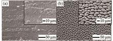
Objective The wettable functional surface in nature continues to be a great impetus to application of functional surfaces, which attracted widespread attention. Inspired by the porous surface of plants such as moss, many studies on the surface of superhydrophilic micro-nano structure have been carried out, which demonstrate that it has the ability to anti-fog and heat transfer enhancement. To further confirm that the surface wettability is unstable which will change with storage time in dark. Therefore, maintaining the stability of surface wetting has been challenging for the surface application of hydrophilic micro-nano structures. The current studies of wettability transition mechanism are built on different material surfaces and different storage environments, no systematic study concerning the influence of different wetting transition mechanisms on a single material has been published yet. In addition, there are relatively few studies devoted to surface wettability and surface morphology are also closely related, and for the same conversion mechanism, the effect of different surface morphologies on the overall macroscopic wettability. Therefore, it is necessary to comprehensively study the transformation and suppression of surface wettability from the aspects of surface morphology and surface energy, which is of great importance for maintaining the stability of the wettability of hydrophilic surfaces, and find application where the functional surfaces with hydrophilic properties is desired.Methods The employed laser was an amplified Ti: sapphire femtosecond laser system that generates light pulse at central wave-length of 800 nm, with pulse energy of 4 mJ and pulse duration of 50 fs at a 1 kHz repetition rate. Laser with different laser energy densities (adjusted via energy attenuator) were used to manufacture two kinds of sub-micron and columnar structure surfaces on the surfaces (304 stainless steel) via laser direct writing, denoted as SL and SH, respectively. The samples without chemical treatment were marked as SL-Air and SH-Air, respectively, and the sample after soaking in sodium hydroxide solution were marked as SL-NaOH and SH-NaOH, respectively, and all of samples were stored in a same dark environment. Optical contact angle measurement equipment was used to measure the contact angle and infiltration time every seven days in order to draw curves of contact angle with time. Meanwhile, scanning electron microscope (SEM) and X-ray photoelectron spectroscopy (XPS) were used to analyze the change of surface morphology and chemical composition.Results and Discussions Initially, 304 stainless steel surfaces with different structures had excellent hydrophilicity, but the changes of surface contact angle were more obvious for the surface via low-energy compare with high-laser energy (Fig. 3). Generally, the surface wettability is mainly affected by the surface morphology and surface energy. But, the surface morphology of SL was relatively flat, the influence of the surface morphology on the wetting characteristics could be ignored. Therefore, the change in the surface wettability was mainly depends on surface energy which caused by the adsorption of foreign chemicals at the surface defect sites. According to XPS analysis, the defect sites on the SL-Air could adsorb organic matter in the air (Fig. 6), resulting in a decrease in surface energy and reduced its wetting. The wettability of SL-NaOH also decreased (Fig. 3), this was because the surface defect sites of SL-NaOH were first occupied by hydroxyl groups, and then as the sample was stored in the air for time, the hydroxyl groups were replaced by oxygen (Fig. 8). But its surface energy decreased slower than SL-Air, so the rate of the contact angle change in SL-NaOH was smaller, which was the sodium hydroxide solution immersion method delays the transition of surface wettability. As for the surface process via high-laser energy, the contact angle of the sample surface was still 0° for a period of time in part due to the fact that the surface wettability was not only affected by surface energy, but also surface morphology and capillary effect. The increase in the infiltration time (Fig. 4) reflects the surface energy also decreased. However, the presence of roughness and capillary effect could slow down the influence of surface energy on wettability, resulting in a relatively stable surface in wettability for a period of time.Conclusions In this article, the wettability changes of 304 stainless steel surface after femtosecond laser irradiation were systematically studied. The contact angle measurement and surface energy spectrum analysis showed that the change in wettability, which mainly related to the adsorption of surface chemical substances. The change of surface wettability without chemical treatment was mainly related to the adsorption of organic substances while for the surface after soaked in sodium hydroxide was not, which demonstrates that the post-treatment could effectively intervene in the process of wetting transition and change the transformation mechanism (from the original organic matters adsorption dominanced to oxygen adsorption dominances), therefore make an optimization for the hydrophilic properties of the surface. The way of post-processing intervention is expected to become a new method to maintain the hydrophilic properties of the surface which has a more significant impact on the surface with low roughness prepared by low laser energy. Moreover, when a superhydrophilic surface with a larger degree of roughness is fabricated, the superhydrophilicity can be maintained for a longer period of time due to the stronger capillary effect even though the wettability is reduced. Therefore, this article provides an effective method and strategy for maintaining the hydrophilicity of the surface in terms of micro-nano structure and surface chemical composition, which is of great significance for the application of hydrophilic surfaces.
Sep. 06, 2021Vol. 48 Issue 18 1802001 (2021)
Chuang Cai, Jia Xie, Zhijie Liu, Hanping Wang, and Hui Chen
Objective Aluminum alloys are widely used in high-speed train manufacturing industry owing to their lightweight, high strength, and good wear resistance. Compared with conventional metal inert gas (MIG) welding, laser-MIG hybrid welding has great application prospects for the welding of aluminum alloys because this welding technology exhibits deeper penetration depth, higher welding speed, better gap and misalignment adaptability, and smaller welding residual stress and distortion. However, the suppression of porosity defect in the weld seam is one of the main problems for laser-MIG hybrid welding of aluminum alloys and needs further investigation. Currently, several studies have focused on the suppression of porosity defect using different methods, including optimization of the position and energy ratio of laser and arc sources, optimization of assist gas or welding shielding gas, welding under subatmospheric pressure, and welding with the weaving laser beam. However, previous studies on weaving laser welding were focused on single laser welding. Few studies have discussed the effects of weaving laser on the porosity defect of laser-MIG hybrid welded joints. In this study, the laser-MIG hybrid welding experiments of A7N01P-T4 aluminum alloys with different weaving diameters and frequencies were performed. The influences of weaving diameter and frequency on the droplet transfer behavior, weld formation, and weld porosity defect were investigated. Furthermore, the mechanism of porosity defect suppression was presented.Methods In this study, the A7N01P-T4 aluminum alloys with a thickness of 12 mm and ER5356 filler wire with a diameter of 1.2 mm were used. A 4-kW laser (IPG YLS-4000) and an arc welding machine (Kemp Arc-450) were used for the bead-on-plate laser-MIG hybrid welding experiments. A laser-leading hybrid welding with a circle-mode weaving laser was adopted during the welding process. The welding parameters are as follows: laser power of 4 kW, welding speed of 1 m/min, wire-feeding speed of 8.0 m/min, laser-weaving diameters of 0.2 and 2 mm, and laser-weaving frequencies of 30 and 50 Hz. A high-speed video (Photron Fastcam SA4) with a frame rate of 5000 frame/s was used to monitor the effect of weaving laser on the droplet transfer behavior. The porosity defects of the weld seams were observed using the digital X-ray detected machine (ERESCO 65MF4). The porosity ratio of the weld was measured using the ImageJ software. Furthermore, the mechanism of the porosity suppression was presented by discussing the keyhole and molten pool behaviors characterized by numerical simulation.Results and Discussions According to the images obtained from high-speed video, the spatters of the droplet during the traditional laser-MIG hybrid welding process could be efficiently suppressed using a weaving laser. The stability of the droplet transfer was improved. The weld penetration depth decreased with the increase of the weaving diameter. The weld penetration depth increased with the decrease of the weaving frequency. Large weaving frequency (Fig. 4) was used to obtain more concentrated energy distribution and high intensity of energy. The size of the keyhole opening was enlarged using the high-weaving frequency such that more laser energy could be absorbed. The porosity defects of the weld were suppressed efficiently. While the laser-weaving diameter was 0.2 mm, the weld porosity ratio was ~2.4%, which was efficiently reduced compared with ~7.8% weld porosity ratio of the conventional hybrid welding. The numerical simulation results showed that the size of the keyhole opening increased by 37% with a weaving diameter of 0.2 mm compared with that of the traditional laser-MIG hybrid welding (Figs. 6 and 7). The longitudinal lengths of the molten pool increased by 15% and 31% with the weaving diameters of 0.2 and 2 mm, respectively. The porosity defect in the weld seam was related to the keyhole stability and molten flow behavior. Compared with traditional welding, the fluctuation of the predicted keyhole depth was smaller (Fig. 10), which was beneficial for the suppression of bubbles formed during the welding process. Additionally, the fluid flowed downward at the middle of the keyhole rear, which was beneficial for the escape of bubbles from the molten pool while applying the weaving laser (Fig. 11). Consequently, the porosity defects were significantly suppressed during the weaving laser-MIG hybrid welding process.Conclusions During the laser-MIG hybrid welding process of aluminum alloys, the welding spatters can be suppressed and the stability of the droplet transfer can be improved by applying the weaving laser. The weld formation of the laser zone is improved, and a more uniform weld seam along the direction of the sample thickness can be obtained. Besides, the porosity defects of the weld are suppressed efficiently. When the laser-weaving diameter is 0.2 mm, the weld porosity ratio is ~2.4%, which is efficiently reduced compared with ~7.8% weld porosity ratio of the conventional hybrid welding. In the conventional laser-MIG hybrid welding, the bubbles generated at the bottom of the keyhole cannot escape from the molten pool because the fluid flows downward under the keyhole, and the vortex is formed. Consequently, more porosity defects are formed. A weaving laser with small weaving diameter is applied, the keyhole with a large size is formed and its stability is improved. Besides, the fluid flows downward at the middle of the keyhole rear, which is beneficial for the escape of bubbles from the molten pool.
Aug. 23, 2021Vol. 48 Issue 18 1802002 (2021)
Zhanjiang Zhai, Lin Zhao, Yun Peng, Jiao Zhu, and Yang Cao
Objective The fatigue properties of automobile body structural materials should be considered in design and material selection when the automotive body experiences a cyclic load. When the plastic deformation occurs under a certain cyclic load, the fatigue cracks initiate more easily from the stress concentration zone where the plastic deformation occurs. Therefore, it is very important to understand the low cycle fatigue performance of automotive steels. Under the condition of plastic deformation, the laser welded joints of automotive steel possibly undergo the process of cyclic hardening or cyclic softening, and they possibly maintain a cyclic saturation stage, so the strain-life curve and the hardening-softening behavior of a periodic cycle become a basis for material selection. After laser welding, the welding joints of DP980 steel are composed of fusion zone and heat affected zone (HAZ). The study of DP980 steel welding joints shows that the subcritical HAZ softening is due to the formation of tempered martensite. In this paper, DP980 steels are welded using a 2 kW fiber laser at different welding speeds with a constant laser power and defocus quantity. Three welding joints are obtained by adjusting welding speed. By studying the low cycle fatigue properties of base material and welded joints, it is a great significance to select suitable welding parameters.Methods Firstly, the laser welding experiment of DP980 steels was carried out using a YSL-2000 fiber laser system. The laser welding parameters were listed in Table 1. The welding direction was parallel to the rolling direction of base material. Second, the specimens were cut from the welding cross-sections and then mounted, ground, polished, and etched with 4% (volume fraction) Nital solution. The microstructures of welding joints were observed by an optical microscope (OM) and scanning electron microscope (SEM). The Vickers microhardness of welding joints was measured on etched specimens by the microhardness tester under a 100g load and a 10 s dwell time. Third, the dimensions of fatigue specimens were machined as shown in Figure 1. Lastly, the fracture surfaces were observed by SEM to examine the failure locations and fracture surface morphologies.Results and Discussions The welding joints are composed of fusion zone, supercritical HAZ, intercritical HAZ, and subcritical HAZ (Fig. 3). From the fusion zone to the base material, the microhardness decreases firstly and then increases (Fig. 4). The static tensile failure positions of welding joints are all in subcritical HAZ (Fig. 5). Under the same strain amplitude, the base material has the best anti-fatigue property. When the stain amplitude Δεt/2≤0.4%, the fatigue life of the 80 J/mm welding joint is better than those of the 100 J/mm and 133 J/mm welding joints (Fig. 11). When the strain amplitude Δεt/2=0.5%, the fatigue life of three laser welded joints is similar (Fig. 6). When the strain amplitude Δεt/2≥0.3%, the base material and the laser welded DP980 joints undergo three stages of cyclic softening stage, saturation stage, and cyclic softening stage. When the strain amplitude Δεt/2=0.25%, the base material and the laser welded DP980 joints undergo four stages of cyclic hardening stage, cyclic softening stage, cyclic saturation stage, and cyclic softening stage (Fig. 9). For the 100 J/mm and 133 J/mm welding joints, the fatigue fracture zone is located in the subcritical HAZ (Fig.11). The tempered martensite and a large amount of carbides are near the fracture surface, and a certain number of voids are formed near the fracture surface (Fig. 12). The fatigue fractures are composed of the fatigue crack initiation region, the crack propagation region, and the final fracture region. The base material and the 80 J/mm welding joint have a single crack source, and the crack propagation zone is radial. The 100 J/mm and 133 J/mm welding joints have a multi-source crack source, and the crack propagation zone is flat (Fig. 13). With the increase of strain amplitude, the cumulative damage of plastic deformation is more obvious, the spacing of secondary cracks becomes larger, and the fatigue striation is not obvious on the fracture surface. The fracture surface of the crack propagation region is of brittle fracture, which is sugar-like. The fracture surface is characterized by transgranular fractures (Fig. 14).Conclusions The microstructure and fatigue properties of laser welded DP980 steel joints under three different heat inputs have been studied. The results show that the subcritical heat affected zone is the main place of crack initiation for the 100 J/mm and 133 J/mm welding joints. When the stain amplitude Δεt/2≤0.4%, the 80 J/mm welding joints have a better anti-fatigue property. The fatigue crack propagation zones have fatigue striation. Fatigue fracture mode is a transgranular fracture.
Aug. 27, 2021Vol. 48 Issue 18 1802003 (2021)
Wei Wang, Jie Shen, Weijun Liu, Hongyou Bian, Qiang Li, and Yu Zhou
Objective TA15 titanium alloy is often used to manufacture aircraft partitions, wall plates, welding bearing frames, and aircraft engine parts. These parts often need to withstand high temperatures and various stresses. However, the oxide layer on the surface of such parts reduces its welding performance, electrical conductivity, and bonding with the coating; therefore, it is necessary to clean the oxide layer film regularly. Compared with the traditional cleaning methods, laser cleaning technology has the advantages of high precision, broad applicability, simple process, and clean and green. As a new type of laser, pulsed fiber laser has the advantages of high photoelectric conversion efficiency, good beam quality, and high reliability compared with other lasers. This can solve the problems of poor consistency and low efficiency for cleaning some parts of the existing aircraft. This laser cleaning breaks the technical bottleneck of the traditional aircraft cleaning process regarding the cleaning mechanism, which is conducive to improving aircraft re-service safety and service life. It provides the scientific basis and technical support for the popularization and application of laser cleaning technology in aviation and other major equipment. This also ensures the safety of equipment in service to promote the green and high-quality development of Chinese industries including aviation, marine equipment, and rail transit.Methods In this study, a TA15 titanium alloy plate with oil stain and an oxide layer on the original surface was used. First, we used an IPG pulsed fiber laser and different scanning speeds of galvanometers to clean the original surface of TA15. Then, the surface morphologies of TA15 before and after the laser cleaning were observed using an ultra-depth three-dimensional field microscope to determine the feasibility of laser cleaning the oil stain and oxide layer on the TA15 surface. Then, a scanning electron microscope, an energy spectrum analyzer, and an X-ray diffractometer were used to observe and analyze the effect of different scanning speeds of galvanometers on the surface morphology, surface-element content, and surface composition of the cleaned TA15 surface. Simultaneously, the removal mechanism of the oil stain and oxide layer on the TA15 surface was studied. Finally, the hardness of the TA15 surface before and after the cleaning was tested using Vickers hardness tester to explore the influence of laser cleaning on the TA15 surface and the relationship between the scanning speed of the galvanometer and hardness during the laser cleaning.Results and Discussions After pulsed laser cleaning, the original black surface of TA15 becomes white and bright. The scanning speed of the galvanometer has a certain influence on the cleaning effect [Fig.1(a) and Fig.4]. When other laser cleaning process parameters remain unchanged, the overlap ratio of galvanometer spot increases with the decrease of scanning speed. This leads to an increase in the laser energy absorbed by the cleaning surface so that the porous and loose oxide layer on the TA15 surface can be removed. Moreover, the surface cleaned with the small scanning speed of the galvanometer is smoother than the surface cleaned with the large scanning speed, and the removal effect of the oxide layer is also more obvious [Fig.1(b) and Fig.5]. Combined with the principle of laser cleaning and the oxide debris observed on the surface of the TA15 alloy, it can be inferred that gasification and phase-explosion mechanisms are followed during the laser cleaning process for the oxide layer and oil stain on the TA15 surface. Because the air and moisture contained in the porous structure of the original oxide layer explode under the irradiation of the laser, phase-explosion is caused in the cleaning surface. Additionally, some oil stain can be attached to the oxide layer debris generated by the phase-explosion and removed together (Fig.6). Due to the element content changes on the cleaning surface, as the scanning speed of the galvanometer increases from 7000 mm·s -1 to 10000 mm·s -1, the Ti-element content on the TA15 surface first increases and then decreases, while the O-element content first decreases and then increases (Fig.7). The oil stain and oxide layer on the TA15 surface cannot be well cleaned when very high scanning speed is used. However, very low scanning speed can easily cause thermal oxidation of the cleaned surface and generate new Al2O3 and TiO2 layers that adhere to the cleaned surface (Fig.8). Through the analysis of the change of the hardness of the cleaned surface, it is concluded that the plasma and phase-explosions can cause the plastic deformation of the TA15 surface and the refinement of the grain, which can produce the effect of laser shock strengthening and improve the surface hardness of TA15. With the decrease of scanning speed, the effect of laser shock strengthening is also improved (Fig.9). Conclusions The scanning speed of the galvanometer in pulsed laser cleaning is an important factor influencing the cleaning effect of oil stain and oxide layer on the TA15 surface, and the removal mechanisms of the oil stain and oxide layer on the TA15 surface are mainly gasification and phase-explosion mechanisms. When the scanning speed increases from 7000 mm·s -1 to 10000 mm·s -1, the surface cleaning effect of TA15 is the best at the scanning speed of 8000 mm·s -1. At this time, the Ti-element content of the cleaned surface reaches the highest value of 79.47%, and the O-element content reaches the lowest value of 8.62%; the surface Al2O3 is almost removed, and the TiO2 content is low. Laser cleaning can strengthen the TA15 surface by laser shock and improve the hardness of the cleaning surface. Reducing the scanning speed of the galvanometer will enhance the effect of laser shock strengthening and increase the hardness of the cleaned surface.
Sep. 06, 2021Vol. 48 Issue 18 1802004 (2021)
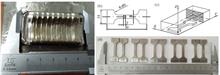
Genyu Chen, Peixin Zhong, and Shaoxiang Cheng
Objective With the rapid advancement in optoelectronic technology, laser-assisted glass frit bonding technology is being commonly utilized in the packaging process of photoelectric devices. Despite its popularity, there are defects such as pores, cracks, non-fusion, and low joint strength, whose formation is not yet well understood. To better understand and eliminate these defects, the glass frit bonding process needs to be accurately monitored in real time. Existing works focus on monitoring the important physical parameters but lacks a visual analysis of the bonding process. In this study, we directly observed the coupling process between the molten frit and the base metal surface in glass frit bonding. In addition, we expounded on the expansion mechanism of the glass frit and the formation of pores in the bonding process. The results point to new possibilities for eradicating defects in laser-assisted glass frit bonding.Methods In the test, we use a 0.7 mm thick borosilicate glass (Corning EAGLE XG) as the glass substrate and low-temperature frit (BASS) as the frit. The glass substrate is cleaned using ultrasonic waves with a mixture of distilled water and detergent and dried to remove dust, oxides, and other pollutants on the glass surface. The frit is printed on the glass substrate with a 400-mesh silk screen (18 μm steel mesh thickness and 10 μm film thickness). The silk screen pattern is a straight line (length of 30 mm and width of 0.8 mm). The sample is placed in a heating furnace to remove impurities. The heating process is divided into three steps: a) First, directly heating the coated glass substrate to 150 ℃ in air to remove the organic solvent; b) then, increasing the temperature to 300 ℃ to burn out the binder; c) finally, heating to the glazing temperature to complete the presintering of the glass frit. Before heating, the specimens are placed at room temperature for 10 min. In the heating furnace, the heating rate of the sintering process is maintained at 5 ℃/min, and the cooling rate is not controlled during the cooling process (Fig.1). Another glass plate is covered above the glass plate with the frit and laser is used to realize the bonding of two glasses (Fig.2). We build the laser test platform using a continuous laser semiconductor and capture the laser bonding process using a coaxial camera system (Fig.3).Results and Discussions When the input laser energy was sufficient, the frit coating area was completely connected with the glass cover plate. When the laser energy was insufficient, the connection width was insufficient to cover the frit coating area. When the laser energy was excessively high, the frit was fully melted because of the sufficient absorption of high energy. The molten frit moved to both ends, expanding the connecting region. Numerous pores appeared after the expansion of the bonding area (Fig.5). The particle impurity appeared before the molten frontier. Because the laser energy absorption of the impurity was higher than that of the surrounding glass frit, low-temperature glass frit around the impurities was decomposed and gasified. The gas in the gaps around the impurities and the gas from the gasification gathered and formed impurity-type pores (Fig.7). When the size of the impurity particle was relatively large, the size of impurity-type pores was positively correlated with the size of impurity particles and the laser power (Fig.8). At this time, the impurity particles were larger, and because of the formation of larger pores, the pores did not separate when moving with the melt front but formed a connected shape. When the input laser power was excessively high, part of the low-temperature frit in the melting frontier was decomposed and gasified, resulting in intensity-type pores when combined with the residual gas. The intensity-type pores surrounding the impurity-type pores were squeezed, and some of them were incorporated into the impurity-type pores (Fig.9). After the formation of impurity-type pores, they moved toward the center of the connecting position (Fig.10). When the intensity-type pores appeared, the movement was in the opposite direction. When the laser beam was biased upward by 0.2 mm, the pores formed in the melting frontier moved to the side edge and disappeared. Then, larger pores appeared. Those pores kept moving to the side of the melt pool while growing, but as they overflowed, only smaller pores remained.Conclusions In this study, we built a platform to observe the laser-assisted glass frit bonding process and visually analyzed the coupling behavior between glass substrates and frit. Such a platform can be used for real-time monitoring of bonding quality. Based on the observed results, we analyzed the coupling behaviors in various cases. In the coupling process between glass substrates and frit, the pores are divided into impurity- and intensity-type. The expansion of the bonding area is typically accompanied with the formation of intensity-type pores, and impurity-type pores are occasionally formed in any coupling behavior. When the intensity-type pores do not appear, they tend to move toward the center of the bonding area; when the intensity-type pores appear, they move to the side or even overflow the bonding area. If the impurity-type pores cannot be effectively controlled, the gas in the bonding area can be forced to escape by the way of biasing the laser beam, so as to avoid the formation of large pores almost throughout the whole bonding area.
Aug. 23, 2021Vol. 48 Issue 18 1802005 (2021)
Jinzhao Liu, Tingyan Yan, Xufeng Kang, and Xiaohong Zhan
Objective In recent years, the aerospace manufacturing industry has proposed the requirements for large-scale and lightweight aircraft, and weight reduction has become the first priority of the aircraft manufacturing industry. Dual-laser-beam bilateral synchronous welding (DLBSW) is an innovative manufacturing process for producing the skin-stringer T-shaped structure, which was first proposed by Airbus. Currently, the study of DLBSW has mainly focused on the skin-stringer T-joints of aluminum alloy, with only a few references to the Ti6Al4V alloy T-joints and their properties. This T-joint forms a molten pool under the action of bilateral laser beams during the process of DLBSW, and the thermal effect is superimposed at the bottom of the molten pool. Because the Ti6Al4V alloy is sensitive to thermal action, the equiaxial grain in the heat-affected zone (HAZ) is easily coarsened during welding, which weakens the mechanical properties and service performance of the T-joint. Therefore, a rational selection of heat input is necessary for the laser welding of the titanium alloy. This study aims to reveal the influence of laser power on the microstructure of the Ti6Al4V alloy T-joint and explore the influence of microstructure on the fracture performance of the joint.Methods In this study, the DLBSW experiment of the Ti6Al4V alloy T-joints was performed using two KUKA robots and a TruDisk 12003 laser produced by TRUMPF. The laser and the laser welding head are connected by two optical fibers. During the welding process, the laser beam and shielding gas were delivered symmetrically along the center line of the stringer (Fig. 1). Following the welding experiments, two groups of well-formed T-joints were selected for metallographic and tensile specimen preparation. The specimens were cut along the cross-section of T-joints, and the uneven area is avoided. The microstructure of the joint after polishing and corrosion was observed under an MR-5000 metallographic microscope. The tensile experiment was performed using an electromechanical universal testing machine at 25 ℃. The loading rate was set to 0.8 mm/min, and the fracture morphology was observed using a scanning electron microscope.Results and Discussions When the laser power is 2.1 kW, the HAZ above the upper fusion zone of the joint can be divided into the obvious coarse grain region (CGR), fine grain region (FGR), and transition region (TR) owing to the thermal effect of the molten metal on both sides of specimen. There is a large area of TR below the lower fusion zone without the obvious CGR and FGR (Fig. 6). The fracture surface of the joint is near the HAZ, and the tensile strength exceeds 800 MPa (Fig. 8). When the laser power is 2.3 kW, the α' phase that precipitated inside the columnar crystal in the weld bead zone coarsenes significantly because of the increase in heat input. Additionally, different from the joint adopting laser power of 2.1 kW, the HAZ below the lower fusion zone of joint No.2 can be divided into the CGR, FGR, and TR owing to the increase in laser power. A wide CGR appears below the lower fusion zone, where the grains have severely coarsened and some of the equiaxed grains have increased to 100 μm in size (Fig. 7). The joint is invalid in the weld bead zone, and the tensile strength is only 478 MPa (Fig. 8). The fractographs of the joint are mixed, except for the equiaxed dimples, and the exfoliated lamellar α' phase interface can be found on the fracture surface. It can be concluded that the fracture mode of specimen No.3 is a hybrid fracture, comprising both the cleavage and ductile fractures (Fig. 11).Conclusions Experimental results indicate that the Ti6Al4V alloy T-joint manufactured by DLBSW is more sensitive to changes in the laser power. When the laser power increases, a large area of CGR is observed below the lower fusion zone, with some grain size reaching 100 μm. However, the region below the lower fusion zone of the joint adopting the laser power of 2.1 kW is a wider TR, while those of the CGR and FGR are not obvious. The joint under the laser power of 2.1 kW failed in the HAZ on the skin when a higher tensile strength exceeded 90% of the strength of the base material. When the laser power is increased to 2.3 kW, the joint is fractured in the weld bead zone, and its strength is significantly reduced compared with the specimen adopting a laser power of 2.1 kW. According to the fractographs of the joint, the fracture mode of the joint under lower laser power is a microporous aggregation fracture, which is classified as a ductile fracture. When the laser power is increased to 2.3 kW, the fracture mode of the joint is a combination of the ductile and cleavage fractures, with a mixed morphology comprising equiaxed dimples and exfoliated lamellar α' phase interface.
Sep. 06, 2021Vol. 48 Issue 18 1802007 (2021)
Kangmei Li, Xingzhe He, Yu Cai, and Jun Hu
Objective Aluminum alloy has the advantages of low density and great strength; therefore, it is commonly used in several industries. However, aluminum alloy is difficult to be welded via fusion welding, which limits its utilization in the aerospace field. Friction stir welding (FSW) can conveniently solve this problem. Nevertheless, tensile residual stress is introduced by FSW during the welding process, affecting the mechanical properties of the joint; therefore, strengthening the joint is essential. Laser peening (LP) is a technology that uses instantaneous shock pressure to strengthen the impacted parts, and the mechanical properties of the impacted parts will be improved by introducing compressive residual stress on the surface and subsurface of the materials. Currently, LP is commonly utilized in the modification of metal materials. Simultaneously, research concerning the utilization of LP to modify metal welds is advancing. However, there are few studies regarding LP strengthening for friction stir welding zone, particularly the finite element simulation for the composite process. In this study, a finite element model of the FSW and LP composite processes was developed to investigate the effect of LP on the residual stress in the friction stir welding zone of aluminum-lithium alloy and examine the cause of stress wave attenuation under various processes.Methods In this study, a composite process model was developed using Hypermesh and ABAQUS software. The simulation analysis was divided into two processes: FSW and LP. First, the sequential coupling approach was adopted during the simulation process of FSW. The Dflux subroutine was called as the heat source program to calculate the welding temperature field, and the stress analysis was carried out based on the temperature field. Then, the LP simulation was performed with welding stress filed as the initial condition, and the Vdload subroutine was called as the shock pressure program for LP simulation. Finally, a stable residual field was achieved. Next, the residual stress values along the X, Y, and Z axes were extracted for comparative investigation, taking the center of the welding as the original node. Moreover, the attenuation law of stress wave was summarized by comparing the propagation phenomenon of stress wave after LP and composite process, and the reason for this phenomenon was explained.Results and Discussions By studying the residual stress distribution diagram of the sample under various treatment processes, we discovered that the tensile residual stress was caused by FSW, the residual compressive stress was caused by LP, and the tensile residual stress in the welding zone treated by the composite process substantially decreased (Fig.10). In addition, by studying the residual stress distribution diagram of the sample after the composite process, we discovered that the residual stress field generated by the composite process was not equal to the linear superposition of the residual stress field generated via LP and the residual stress field generated by FSW but was determined by the coupling effect of the two processes (Fig.11). The reduction of residual stress caused by LP and the value of residual stress caused by FSW were further studied, and we discovered that the reduction of residual stress was positively correlated with the residual stress caused by FSW (Fig.12). Based on the stress wave propagation law, we discovered that the attenuation of the internal stress wave of the sample treated by LP and the sample treated by the composite process exhibited an exponential changing trend. As the plastic wave transformed into an elastic wave, the stress wave decayed faster in the initial stage compared with the later stage (Fig.13). The stress wave generated by the composite process decayed slightly faster compared with the LP process. The possible reason for this phenomenon was that tensile residual stress caused by FSW. The introduced tensile residual stress increased the conversion rate of stress fluctuation energy into plastic deformation energy to offset the tensile residual stress. Consequently, the stress wave attenuation rate of the composite process rapidly decreased (Fig.14).Conclusions In this study, a finite element simulation model for the composite process of FSW and LP was developed. The accuracy of the model was proven by comparing it with the experimental results in a related study. The model was used to simulate the FSW, LP, and composite processes. The differences among the residual stress distribution of the samples treated via various processes were compared. The study discovered that FSW introduced tensile residual stress on the surface and subsurface of aluminum-lithium alloy, whereas the LP introduced compressive residual stress. In addition, the tensile residual stress in the welding zone treated by the composite process was effectively reduced. Furthermore, the residual stress caused by FSW was found to be positively correlated with the reduction of residual stress, whereas it did not affect the affected area of LP. The propagation law of the stress wave in the material was investigated, and we discovered that the composite process attenuated the stress wave faster than the LP process. Therefore, under the same laser parameters, the reduction of residual stress caused by the composite process was greater than that caused by LP. Thus, the strengthening impact of LP on the aluminum-lithium alloy’s friction stir welding zone was superior to that of aluminum-lithium alloy.
Sep. 06, 2021Vol. 48 Issue 18 1802008 (2021)
Yuchao Bian, Yingbo Peng, Lingfeng Song, Hongwei Tang, Guanglu Cai, Gaoyan Zhong, and Shoufeng Yang
Objective Currently, traditional engineering materials are facing the contradiction between strength and toughness. Several organisms in nature have comprehensive high strength and toughness properties owing to the long-term evolution of heterogeneous characteristics; thus, they have become a model for people to imitate. However, achieving heterogeneous forming using the traditional manufacturing process is difficult; the selective laser melting (SLM) with high degree of freedom and precision provides a new opportunity for forming parts with this feature. Currently, the heterogeneous forming of SLM is mainly achieved through multimaterial and different-layer forming. However, the studies regarding the same-layer forming are inadequate, and the same-layer formed parts’ performance is poor compared with different-layer formed parts. The reason is that the laser penetration is reduced in the same-layer forming, and the overlapping efficiency of the melt pool at the boundary is poor, leading to poor bonding quality between heterogeneous materials, making it difficult to achieve metallurgical bonding. Therefore, this study improved the interface bonding quality of SLM316 L/IN718 heterogeneous parts with the same layer based on optimizing the laser remelting process. In addition, the mechanical properties of the remelted parts were significantly improved compared with those without remelting, making further innovation and expansion to form SLM bionic structure materials.Methods The metal materials used in this study are atomized 316L and IN718 powders. After laser remelting, the top surface morphology and roughness of 316L were observed and measured using a laser confocal microscope. For heterogeneous forming of different layers 316L/IN718, the sequence of 316L-IN718-316L was used, and the upper surface of each material was remelted after forming. For heterogeneous forming of the same-layer 316L/IN718, the intermediate IN718 was formed after forming both sides of 316L, and laser remelting was performed at the interface joint. Scanning electron microscope (SEM) and energy dispersive spectrometer (EDS) were used to observe the microstructure and element distribution of the interface. The tensile test was performed at room temperature using DDL100 electronic universal testing machine at a strain rate of 3 mm/min, and the tensile strength and elongation were measured. Finally, SEM was used to observe and analyze the fracture morphology of tensile specimens.Results and Discussions The effect of different laser remelting parameters (laser power, scanning speed, and remelting times) on the surface roughness of 316L is different (Fig. 5). When the laser power is 300 W, scanning speed is 250 mm/s, and remelting times is 5, the surface roughness exhibits the lowest values of 2.4, 2.4, and 2.7 μm. After laser remelting, the surface quality of 316L parts is effectively improved, indicating that this optimization process is expected to improve the interface bonding quality of heterogeneous parts, and the interface transition zone of 316L/IN718 heterogeneous layer becomes smoother with a width of 450 μm (Fig. 7). However, the interface bonding quality of the 316L/IN718 heterogeneous layer is poor without remelting and the pore diameter is approximately 0.18--0.35 mm. Moreover, after remelting, the spheroidization and pores in the transition zone almost disappear, and the interface bonding quality is improved (Fig. 8). EDS analysis results show a gradient trend in the element diffusion of same-layer 316L/IN718 heterogeneous parts after laser remelting. Consequently, the distribution of Fe, Ni, and other elements is more uniform (Figs. 9 and 10). The tensile test results in Fig. 11 show that the tensile strength of remelted sample increases from (104.77±45.26) to (507.33±58.3)MPa and the elongation is approximately 11%. This proves that the laser remelting optimization process improves the performance of SLM 316L/IN718 heterogeneous components. The fracture morphologies of same-layer 316L/IN718 tensile parts before and after remelting were observed (Fig. 12). The crack was found to deflect at the poor joint, leading to rapid fracture failure of the sample without remelting; however, no obvious transition was observed at the fracture after remelting optimization, indicating that 316L and IN718 exhibit good metallurgical bonding. Both samples exhibit brittle fracture in macroscopic view. However, numerous dimples and tearing edges are observed at the fracture of remelted specimens, indicating that the fracture mode is brittle and ductile fractures.Conclusions After remelting, the surface roughness of 316L decreases from 7.1 to 2.7 μm by 62%; the flat micromorphology and good element diffusion of the 316L/IN718 transition zone exhibit the effect of remelting in improving the bonding quality of the 316L/IN718 heterogeneous interface. The increase in tensile strength of the sample from (104.77±45.26 )MPa before optimization to (507.33±58.3) MPa after optimization also verifies the feasibility of the optimized process. Both the unremelted and remelted same-layer 316L/IN718 heterogeneous tensile parts exhibit brittle fracture characteristics in the macroscopic view. Simultaneously, the interface joints of the remelted samples exhibit obvious dimple fracture characteristics and no secondary cracks and unmelted powders were observed, indicating that laser remelting can considerably improve the quality of interface bonding.
Sep. 06, 2021Vol. 48 Issue 18 1802009 (2021)
Yangshuai Li, Junyong Zhang, Jianqiang Zhu, Chang Li, Wenwu Zhang, Xiu Qin, Xiangyang Pang, and Mingying Sun
Objective With developing inertial confinement fusion technology, the damage of optical elements due to pollution has gradually become a critical bottleneck, limiting the efficiency of laser drivers. The pollutants on the surface of optical components of laser drivers comprise three types of particles, namely organic matter, metals, and minerals. The formation modes of particle pollutants primarily include microparticles produced on the surface of optical components irradiated by laser, environmental particles introduced during assembly, and particles produced because of the friction of components. The deposition of micron-sized and submicron-sized particles on the surface of optical components can reduce the transmittance of optical components and damage optical components because of local light intensity enhancement. Therefore, it is critical to realize the clean control of micron and submicron particles. Metal (supporting optical element) wall adsorption and particle splashing induced by laser irradiation are important sources of micron and submicron particle pollutants. Currently, the commonly used control methods include mechanical polishing, micro-arc oxidation, black anodization , hard anodizing, and surface microtexture of the metal tube wall. However, most of these methods have problems and shortcomings. Therefore, an effective method to realize the cleanliness control of metal pipe wall pollutants must be explored. Laser-shock processing (LSP) is a new surface strengthening technology with many advantages and application scenarios. However, few studies have been conducted on cleaning control. Therefore, in this study, 5052 aluminum alloy is taken as an example to study the effect of LSP on generating pollutants induced via nanosecond laser irradiation of aluminum alloy to provide new research methods and useful guidance for controlling and generating pollutants due to laser irradiation of aluminum alloy.Methods 5052 aluminum alloy was used in this study. First, 5052 aluminum alloy samples were shock-strengthened using a nanosecond laser with different power densities. The hardness and roughness were evaluated, and surface morphology was observed. Then, 5052 aluminum alloy samples after laser-shock strengthening and samples without laser-shock strengthening were irradiated using a nanosecond laser with different energy densities and cleanliness was evaluated. Finally, a comparative analysis of surface hardness, morphology, and roughness of 5052 aluminum alloy before and after LSP and changes in pollutants induced by laser irradiation were conducted. This study revealed the influence of LSP on the generation of pollutants induced by nanosecond laser irradiation of aluminum alloy.Results and Discussions The surface hardness of 5052 aluminum alloy after laser-shock strengthening under experimental parameters has been considerably improved (14%--20%) (Table 1 and Fig.3), indicating that laser-shock strengthening is effective for improving the surface strength of aluminum alloy. However, the roughness will increase to a certain extent because of the comprehensive macro and micro effects (Fig.3). The number of particles produced by 5052 aluminum alloy increases slowly at first and then increases rapidly, irrespective of LSP (Fig.5). The interaction between the laser and aluminum alloy includes laser cleaning and ablation (Fig.4). When the energy density of laser irradiation is less than 0.65 J/cm 2, the number of particles produced by 5052 aluminum alloy increases slowly as the energy density increases, and laser irradiation only shows the effect of laser cleaning (Fig.6). When the energy density of laser irradiation is less than 0.71 J/cm 2, the number of particles produced by 5052 aluminum alloy increases rapidly as the energy density increases, and laser irradiation shows the effect of laser ablation (Fig.6). Although the roughness of the samples is changed, the roughness of the three samples after strengthening has slight differences and the surface microstructure remains the same (Fig.8), and the roughness has a negligible effect on the laser damage threshold of the materials. Therefore, the number of particles produced in the laser cleaning and ablation stages of the three samples is similar (Fig.7). Conclusions LSP improves the strength of 5052 aluminum alloy, making the surface of 5052 aluminum alloy produce micro-pit structures, enhancing the adsorption capacity of micro-sized and submicron-sized particle pollutants on the surface. Thus, it reduces the probability of producing pollutants under low energy density laser irradiation. This technology is suitable for low energy laser cleanliness application scenarios, such as the low flux operation of laser drivers and clean environment maintenance of aerospace lasers. To further reduce the probability of aluminum alloy contamination under low energy density laser irradiation, the microstructure and distribution of the aluminum alloy surface can be improved by optimizing the laser impact strengthening parameters (such as power density, spot shape, spot overlap rate, laser impact strengthening times, etc.). Furthermore, the properties of the materials determine the laser damage or laser ablation thresholds of aluminum alloy materials and have nothing to do with laser impact strengthening. Therefore, the cleanliness control of high energy density laser irradiation application scenarios can be realized by replacing other high damage threshold metal or non-metallic materials.
Sep. 02, 2021Vol. 48 Issue 18 1802010 (2021)
Zheng Lei, Zongtao Zhu, Yuanxing Li, Yan Liu, and Hui Chen
Objective Laser-arc hybrid welding technology has advantages of high welding efficiency and good joint quality. However, it is currently based on the paraxial composite, which has high requirements for welding direction, and the keyhole instability causes welding defects and other problems. Laser-arc coaxial composite welding has advantages of good heat source symmetry, stable welding process, high joint quality, and good reachability of the welding torch joint. However, research on laser-arc coaxial composite welding is limited because of the difficulty of welding torch head processing. There are two kinds of coaxial recombination, and the structure of passing a laser through a hollow tungsten electrode is relatively simple and easier to achieve than splitting the laser into two beams and then converging them at the focus. However, research on the composite arc characteristics of lasers and hollow tungsten inert gas (TIG) arc has not been reported. Therefore, the study on the characteristics of laser coaxial composite arc in this paper can provide theoretical support for technology development.Methods The mathematical model of laser coaxial composite arc of a fiber continuous laser and 2 mm hollow TIG welding arc under steady-state conditions was established using GAMBIT software. The regional mesh was divided and the minimum mesh was 0.1 mm. The laser heat source, momentum source term, and energy source term were added, and reasonable material physical property parameters were set using user-defined functions (UDF) FLUENT software. The temperature field, velocity field, spatial pressure, electric field, and magnetic field distribution of the coaxial composite arc under 118-A current and 150-W laser power were calculated and compared with those of the hollow single TIG arc under the same conditions. Finally, experiments verify the penetration ability of laser coaxial composite arc.Results and Discussions The calculation results show that compared with the hollow TIG arc, the maximum temperature and high-temperature area of the laser coaxial composite arc increase significantly. The arc’s upper part becomes wider and the arc height increases. The middle temperature above the arc is concave, and the arc’s middle high-temperature area is heart-shaped (Fig.2). The laser coaxial composite arc’s maximum temperature is 19240 K in the cathode region near the electrode, the temperature of the laser irradiation point reaches 18737 K, and the hollow TIG arc’s peak temperature is 15512 K (Fig 3). The flow peak velocity of laser coaxial composite arc plasma is 52 m/s, whereas that of hollow TIG arc is 43 m/s. The plasma flow velocity in the middle and upper parts of the laser coaxial composite arc is faster than that of the hollow TIG arc, but the surface velocity of the workpiece changes little (Fig. 4 and Fig. 5). The maximum pressure of the laser coaxial composite arc on the workpiece surface is 22 Pa, whereas that of the hollow TIG arc is 32 Pa (Fig. 6 and Fig. 7). The pressure of the laser irradiation spot increases. The temperature of the hollow tungsten electrode and pressure in the cavity increase under the action of laser; therefore, the flow of protective gas and plasma flow in the upper part of the laser coaxial composite arc speed up. The reduction in arc pressure can suppress welding defects, such as burning through and gnawing, but the arc stiffness might be reduced. The maximum voltage of the laser coaxial composite arc is -1.7 V, and that of the hollow TIG arc is -6 V. The electric field intensity is reduced by 72% (Fig.8 and Fig.9). The longitudinal magnetic field intensity of the laser coaxial composite arc decreases from 30 mT to 5 mT in the hollow TIG arc, and the transverse magnetic field decreases from 65.6 mT to 1.87 mT, and the transverse magnetic field changes direction (Fig.10 and Fig.11). Under the same current conditions, the surfacing welding penetration of laser coaxial composite arc and hollow TIG arc on Q345 steel is 0.8 mm and 0.5 mm and the widths are 4.3 mm and 4.0 mm, respectively (Fig. 13).Conclusions In this study, FLUENT software was used to simulate the coaxial recombination of laser and hollow TIG arc. Compared with the hollow TIG arc, the peak temperature of the laser coaxial composite arc is increased by 24%, the width of the upper arc is increased, and the top center has a concave of 1.5 mm. The plasma velocity in the middle and upper parts of the laser coaxial composite arc is significantly faster, and the maximum velocity is increased by 21%. The increase in arc temperature and the pressure in the tungsten cavity is the main reason for plasma velocity acceleration, whereas the surface plasma velocity in the anode changes little. The pressure of the laser coaxial composite arc decreases by 31% on the anodic surface of the workpiece, and the pressure at the spots exposed by the laser increases. The electromagnetic field intensity of the laser coaxial composite arc decreases, and the transverse magnetic field direction is reversed. Compared with hollow TIG arc, laser coaxial composite arc has a better penetration ability under the same current conditions, welding depth, and melt width, and welding width increases by 60%, 12%, and 7%.
Aug. 23, 2021Vol. 48 Issue 18 1802011 (2021)
Peng Fan, Jiateng Pan, Yiming Ge, and Yu Zhan
Objective As the core technology which leads the future development direction of the manufacturing industry, laser additive manufacturing (LAM) of functionally gradient materials (FGMs) has attracted significant attention recently. This technology can achieve the gradient change of component composition, microstructure, and properties by adjusting the proportion of powder conveying and laser-forming process. TC4/TC11 gradient titanium alloy has broad application prospects in the manufacture of large and complex key titanium alloy components such as aircraft frame beams and engine blisks. However, because of the periodic, unsteady thermal cycling and the constrained rapid solidification of the moving molten pool in the additive manufacturing process, there is a high residual stress in the formed component. The nonuniformity of the composition of the gradient structure material further complicates the problem. Therefore, studying the temperature and stress fields in the LAM process is particularly important. In this study, the residual stress field of TC4/TC11 FGM fabricated via LAM was analyzed using the finite element method (FEM). The hemispherical heat source function and forced convection model were written in FORTRAN language and loaded into the model using DFLUX and FILM subroutines to achieve the thermal-mechanical coupling finite element analysis of the LAM process. This research has important reference significance for the measurement, control, and reasonable suppression of the residual stress in the additive manufacturing of FGM.Methods The residual stress of TC4/TC11 FGM fabricated via LAM was investigated using FEM. First, the hemispherical heat source model was used as the loading function of the laser heat source. The basic theory and method of composite materials were used to calculate the density, elastic modulus, Poisson’s ratio, yield strength, coefficient of thermal expansion, and specific heat capacity of gradient materials. Second, in the actual modeling analysis, to save the computational cost, half of the model was taken for modeling and symmetry constraints were set on the symmetry plane. Considering the size of the model and computational efficiency, a double-precision grid was selected. The fine grid was set in and near the sedimentary area, while the grid was sparse and far away from the sedimentary area. Finally, the birth-death element technology was used to simulate the additive manufacturing process. The synchronous loading of the moving heat source was achieved by killing and activating the element. The standard thermal-mechanical coupling analysis method was used to calculate the final residual stress.Results and Discussions Temperature and stress fields of the LAM process are calculated using FEM. The temperature distribution of each layer at different time is presented. The temperature of the laser action center is about 1600 ℃. The temperature distribution can approximately describe the situation of the molten pool. The temperature in the center of the molten pool is higher, and the temperature gradient is larger. In the region far away from the laser source, the temperature is lower and the distribution is flat (Fig. 2). The residual stress calculation results show that the residual stress mainly appears in the deposition area, the stress distribution in the middle area is uniform, the stress on the substrate is small, and there is a stress concentration effect at the junction of the substrate and sample. The residual stress along the laser scanning direction is larger than that in the other two directions. Most of the residual stress along the stacking direction is compressive stress; there is a small tensile stress around the specimen and substrate (Fig. 4). The maximum tensile and compressive stresses are 563 and -103 MPa, respectively, which appear in the transition mode Ⅲ. Results show that the stress discontinuity at the interface of the transition mode Ⅲ is obvious; the maximum stress jump value is 200 MPa. The stress distribution tends to be stable, and the stress jump value is smaller under the other two transition modes (Fig. 6).Conclusions In this study, the thermal-mechanical coupling finite element model for residual stress analysis of LAM is established based on the hemispherical heat source model, birth-death element technology, and composite theory. The temperature field calculation results show that the temperature gradient in the laser region is large and the temperature distribution is small and flat in the region far away from the laser source. The results show that the variation in the temperature field under different transition modes is similar. The temperature peak value at the interface of the transition mode Ⅱ is relatively small, whereas that at the interface of the transition mode Ⅲ is relatively large. The residual stress in the LAM process is mainly tensile stress. The residual stress along the laser scanning direction is larger than that in the other two directions. The results show that the distribution of residual stress at the interface of the three transition modes is similar, and the distribution is with the inverted bowl shape. The tensile stress is larger in the middle and then decreases sharply toward both ends; the compressive stress is smaller at both ends. The distribution of residual stress at the interface of different material components is discontinuous. The stress near the side with high TC11 content is larger than that on the other side. The residual tensile stress increases with the increase in TC11 content.
Sep. 06, 2021Vol. 48 Issue 18 1802012 (2021)
Zixun Li, Xiuli He, Gang Yu, Chongxin Tian, Zhiyong Li, and Shaoxia Li
Objective Due to the superior corrosion resistance of Ni and the good hot workability as well as low cost of 304SS, Ni and 304SS joints have been widely used in various industries, such as petrochemical, aerospace, and aviation. Laser welding has the advantages of high precision, high efficiency, and low residual stresses; therefore, it has been considered as a promising joining technology for dissimilar metals. The performance of a welded joint is affected by various factors. One of the most important factors is alloying element mixing within the weld pool (WP). However, processing parameters, such as laser power, scanning speed, and spot offset, can lead to a different element redistribution in the joint. Additionally, the physical mechanisms of element distribution affected by these processing parameters have not been fully investigated. Therefore, this study investigates the element-mixing process within the WP in the laser conduction welding of Ni and 304SS through numerical modeling. The effects of processing parameters on the element distribution in welded joints are investigated. The results show how processing parameters affect dissimilar-metal redistribution and how to obtain a more uniform element distribution with higher dilution by optimizing the process.Methods The transient fluid-flow and element-mixing processes within the WP are difficult to observe directly through experiments. Numerical simulations can be used to predict the dynamic evolution of WP and dissimilar-metal redistribution during laser conduction welding. Therefore, this study develops a numerical model based on the Navier-Stokes equation, coupled with the temperature field, fluid-flow field, and concentration field to analyze the mixing process of the three main alloying elements (Fe, Ni, and Cr). Additionally, the flow characteristics inside the WP are investigated, which are closely correlated to the concentration dilution. The numerical model is validated by comparing the calculated WP profile and distribution of the three alloying element concentrations with the experimental results. Then, the influence of processing parameters on Fe element redistribution in welded joints is analyzed using orthogonal parameter design and range analysis. Additionally, the underlying physical mechanisms of parameters affecting the element distribution are explored based on the model.Results and Discussions The order of magnitude of Peclet number in the transportation of the Fe element is estimated to be 10 4 in the laser welding of dissimilar metals, indicating that convection dominates the mass transfer process. The WP reaches a quasi-steady state for ~50 ms, and the fluid flow in the back section of the WP in the quasi-steady state facilitates the uniform distribution of elements along the z-axis (Fig. 6). Based on orthogonal simulation and range analysis, the range of each level of scanning speed is 9.45%; however, the range of spot offset and laser power is 9.17% and 1.11%, respectively. The scanning speed is negatively related with the average concentration of Fe, whereas the offset is positively correlated with it (Fig. 7). The model’s results show that scanning speed affects the dilution of the Fe element by changing the duration of WP (Table 5) and influences the mushy zone size of WP (Fig. 8). The offset affects the Fe redistribution by changing the longitudinal flow pattern of WP and the relative position of the cross-sectional branch flow to the joint interface (Fig. 9). Conclusions This study establishes a three-dimensional numerical model coupled with the temperature, flow, and multicomponent concentration fields to investigate the WP behavior during the dissimilar welding of Ni and 304SS using laser. The calculated geometry of the fusion zone and the concentration distribution of the main alloying elements (Fe, Ni, and Cr) agree with the corresponding experimental results, verifying the model’s validity. Based on the dimensional analysis, it is found that the transportation of alloy elements is dominated by convection. In the initial stage of WP evolution, the dilution of Fe occurs mainly in the middle section of the WP and tends to stabilize as the WP to reach a quasi-steady state. The WP geometry and velocity show an asymmetric distribution owing to the difference in thermal properties between Ni and 304SS. After WP reaches a quasi-steady state, the fluid flow in the back section of the WP contributes to the uniform distribution of elements along the z-axis. To characterize the element distribution in the WP, the average content of the Fe element flowing into the Ni side is used to design L25(5 3) orthogonal simulation. The most important factors for the distribution of Fe elements are scanning speed (range R=9.45%), spot offset (R=9.17%), and laser power (R=2.11%). Additionally, the average concentration of Fe element flowing into the Ni side is negatively correlated with scanning speed and positively correlated with offset. It is shown that properly decreasing the scanning speed and shifting the spot toward the 304SS side are beneficial for the full dilution and uniform distribution of Fe elements.
Sep. 06, 2021Vol. 48 Issue 18 1802013 (2021)
Jianjun Wang, Kai Tian, Zhijun Chen, Bo Li, Gang Zhang, Qunli Zhang, and Jianhua Yao
Objective Copper (Cu) and its alloys have excellent ductility and good electrical/thermal conductivity. However, their low strength, low hardness, and poor wear resistance restrict their application in industrial and military fields. Adding lubricating phase particles to Cu and its alloys can give the material excellent self-lubricating properties. The Cu-based graphite composite material not only has excellent thermal/electrical conductivity of Cu, but also have low thermal expansion coefficient and excellent solid lubricating property of graphite. Supersonic laser deposition (SLD) is a material deposition technology that combines laser irradiation and cold spray (CS). By introducing laser irradiation, instantaneous heating and softening of the sprayed particles and substrates improve their plastic deformation abilities, which can facilitate the deposition of low-plasticity materials, greatly broadening the range of sprayable materials for CS. Therefore, based on the characteristics and advantages of SLD, we use SLD technology to prepare Cu-based graphite composite coating on the surface of Cu substrate and systematically investigate the effects of different graphite contents on the microstructure, microhardness, and friction of the composite coating in this study. The study can provide a reference for surface modification and additive manufacturing of Cu-based materials.Methods Firstly, graphite/Cu composite coatings with different graphite contents are deposited on Cu substrates by SLD technology. Then, the microstructures and morphologies of the worn surfaces of the composite coatings with different graphite contents are analyzed by scanning electron microscope. The phases and compositions of composite coatings with different graphite contents are analyzed by X-ray diffractometer, energy dispersive spectrometer, and Raman spectrometer. Furthermore, the microhardnesses of composite coatings with different graphite contents are tested by automatic Vickers hardness tester. The effect of graphite content on the microhardness of composite coating is investigated. Finally, wear resistances of the composite coatings with different graphite contents are tested by friction and wear testing machine. The effect of graphite content on wear resistance of the composite coating is elucidated.Results and Discussions The thickness of the composite coating decreases as the proportion of graphite in the original powder increases. When the mass fraction of graphite in the original powder is 5%, 10%, and 15%, the thickness of the composite coating is 908.2, 741.2, and 688.9 μm, respectively (Fig. 3). Owing to the work hardening effect caused by particle impact during the deposition process, the average hardness of the pure Cu coating is as high as 133.60 HV0.2. When the mass fraction of graphite in the original powder increases from 5% to 15%, the hardness of the composite coating decreases from 122.48 HV0.2 to 95.02 HV0.2 (Fig. 7). The wear resistance study of the as-prepared composite coating shows that the mass loss of CuGr0 coating is 4.398 mg. However, when the mass fraction of graphite in the original powder increases from 5% to 15%, the mass loss of the composite coating decreases from 2.058 mg to 0.746 mg (Fig. 8). During the wear process, the graphite in the composite coating can generate continuous solid lubricating films, preventing direct contact between the grinding ball and composite coating and reducing further wear of the grinding ball to the composite coating. Additionally, the morphologies of the worn surfaces of the composite coatings with different graphite contents reveal that the wear mechanism of the coating without graphite is adhesive wear and the wear mechanism of the coating with graphite is abrasive wear (Fig. 11).Conclusions The deposition efficiency of the composite coating decreases as the content of graphite in the original powder increases. Graphite is a soft solid lubricant, increasing its content in the composite coating will reduce the ability of coatings to resist plastic deformation, microhardness, friction coefficient and wear rate.The wear mechanism of the graphite-free coating is adhesive wear. The wear mechanism of the coating changes from adhesive wear to abrasive wear when graphite is added to the coating.
Sep. 06, 2021Vol. 48 Issue 18 1802015 (2021)
Xiongmian Wei, Di Wang, Yongqiang Yang, Changjun Han, Jie Chen, Yunmian Xiao, Xin Zhou, Xinglong Wang, Cheng Deng, and Yingjun Wang
Objective The titanium alloy porous structure has great application prospects in medical implants and lightweight aerospace parts. Studies have shown that human bones suffer from more microdamage in tension than in compression. Currently, researchers have conducted several studies on the mechanical properties and failure mechanism of porous structures using static compression, static tension, and fatigue tests. However, few studies have been conducted on the comparative analysis of tensile properties between lattice porous structures, the relationship between porosity and tensile properties, and numerical simulation. In this study, the tensile specimens of three representative porous structures, namely, body-centered cubic (BCC), BCC with Z-struts (BCCZ), and honeycomb, each with five porosity values are designed. The porous tensile specimens are fabricated using laser selective melting (SLM). The tensile test and finite element analysis of porous structures with different types and porosity are conducted. The findings of this study indicate the influence of the structure type and porosity on the tensile properties of Ti-6Al-4V porous structure and provide a reference for the design and application of porous structures.Methods First, the cell bodies of BCC, BCCZ, and honeycomb structures with different porosities and their tensile specimens are designed using Rhino software. Then, ABAQUS software is used to perform static simulation analysis on the porous tensile specimens. Porous tensile specimens are prepared using the Ti-6Al-4V powder in Dimetal-100 equipment independently developed by the South China University of Technology. Next, tensile tests are conducted according to GB/T 228.1—2010 tensile test method. The fracture morphology of the porous tensile specimens is observed using environmental scanning electron microscopy, and the fracture mechanism is analyzed. The three-dimensional (3D) super depth-of-field microscope VHX-5000 is used to observe the forming condition of the porous structure struts and measure the dimensions of the struts. Finally, the effects of structure type and porosity on the tensile properties of the titanium alloy porous structure are analyzed based on simulation and experimental results.Results and Discussions The tensile mechanical properties of the three types of porous structures (i.e., BCC, BCCZ, and honeycomb) are linearly negatively correlated with porosity, and their elongations are extremely low compared with those of the solid structures (Figs. 7 and 8). Moreover, the study shows that the minimum cross-sectional area of the porous unit body exhibits a linear relationship with porosity (Fig. 12 (c)). This implies that the minimum cross-section of the porous structure decreases linearly with an increase in the porosity, resulting in a linear decrease in the tensile properties. Owing to the small cross-sectional area of the porous structure, the fracture of each porous unit will cause a larger load to be distributed over a smaller cross-sectional area. Therefore, the porous tensile specimens suddenly break after entering a short plastic stage, and their elongations are considerably lower than those of the solid structures. The low elongation of porous tensile specimens can be attributed to the brittle martensite structure (Fig. 4 (b)), powder-sticking phenomenon, and the formation of brittle fracture caused by void defects in the pillar (Fig. 10). The tensile properties of honeycomb porous structures are clearly higher than those of BCC and BCCZ porous structures. This phenomenon can be explained by two reasons. First, the minimum cross-sectional area of the honeycomb structures is larger than those of BCC and BCCZ structures (Fig. 12 (c)). Second, according to stability of Maxwell, honeycomb structures are tensile-dominated structures, whereas BCC and BCCZ structures are bending-dominated structures. Despite the influence of the experimental errors and external conditions, the finite element analysis and experimental results are highly consistent in the regular and elastic stages (Figs. 5 and 11), which can provide an effective reference for the structural design of porous implants in the medical field.Conclusions This study investigates the influence of structure type and porosity on the tensile properties of Ti-6Al-4V porous structures fabricated using SLM based on a combination of finite element analysis and experiments. Simulation and experimental results show that the ultimate tensile strengths of BCC, BCCZ, and honeycomb structures linearly decreased by 348.81, 375.45, and 217.20 MPa, respectively, with an increase in the porosity from 10.91% to 33.84%. This is attributed to a linear decrease in the minimum cross-sectional area of the structures as the porosity increased. All the printed Ti-6Al-4V porous structures exhibited brittle fractures because of the formation of brittle martensite microstructure, powder adhesion to struts, and pore defects inside the struts. Additionally, brittle fractures and the reduction of the cross-sectional area significantly decreased the elongation of the porous structures compared with those of solid structures. The honeycomb structure achieved the best tensile properties among the three, and its specific strength increased with an increase in its porosity. The simulation results are consistent with the experimental results in the regular and elastic stages. The deviation in the plastic stage is relatively large owing to the surface adhesive powder of the inner pillar, internal hole defects, and processing errors.
Sep. 07, 2021Vol. 48 Issue 18 1802016 (2021)
Hongbo Li, Qiangqiang Gao, Kangying Li, and Ban Li
Objective With the development of science and technology and its needs in practical engineering, metal parts are often subjected to extreme conditions, such as high alternating stress, high temperature, high speed, and high corrosion. Therefore, solving the problem of repairing failed parts under extreme conditions is urgent and complicated. It is necessary to analyze and evaluate the failure mode and service life of parts and seek suitable repair materials and process methods. In this study, the hot working die of H13 steel commonly used in engineering is taken as the background, and the strengthening and repair under extreme conditions are taken as the starting point, and investigates the laser cladding strengthening and remanufacturing technology to strengthen various parts suitable for operation under extreme conditions. Repair provides a certain reference significance. Recently, there have been successful study results based on laser cladding; however, the study on Cr3C2-NiCr powder as a laser cladding material is relatively rare. Therefore, Cr3C2-NiCr is selected herein as the cladding material where Cr3C2, as a reinforcing phase, can improve the wear resistance, heat resistance, and hardness of the mold surface. Its physical properties resemble those of H13 steel, thereby reducing the melting cracking caused by material mismatch during the coating process. As an adhesive, NiCr can play a transitional role between the substrate and cladding material and improve the heat and corrosion resistance of the bonded part.Methods Laser cladding technology is used to prepare a cladding layer of H13 and Cr3C2-NiCr composite powder on the surface of the H13 substrate. The microstructure and phase structure of the cladding powder and coating and the bonding characteristics of the coating and substrate are observed and analyzed using scanning electron microscopy (SEM), energy dispersive spectroscopy (EDS), and X-ray diffraction (XRD). The thermal fatigue property of the cladding layer is tested using a thermal shock test. The microhardness of the coating surface and section are measured using a microhardness tester. The influences of various factors on the wear resistance of the substrate and cladding layer are tested using a high-temperature friction and wear tester.Results and Discussions The quality of the cladding layer of the Cr3C2-NiCr composite powder prepared via laser cladding is related to its volume fraction ratio. Compared with other proportioning schemes in the experiment, the cladding layer quality achieves the best performance using the ratio of 85%H13 and 15%NiCr3C2 (Fig. 2). The grain distribution of the cladding layer is uniform; the direction of the dendrite is generally along the substrate and points to the surface of the cladding layer at a certain angle (Fig.3). The structure in the cladding layer is dominated by dendrite, and the main phases are martensite, Cr3C2, Cr7C3, and carbide (Cr·Fe)7C3, among which the martensite diffraction peak is the most obvious (Fig. 5). The surface scanning atlas show that the binding mode between the cladding layer and matrix is metallurgical bonding (Fig. 4). Thermal shock tests show that sample No. 3 with this ratio scheme achieves the best thermal fatigue performance (Fig. 8). The microhardness of the cladding layer surface of the six samples are tested, and the microhardness of the cladding sample surface significantly increased compared with the substrate (Fig. 12 (a)). The surface microhardness of the cladding layer of sample No. 3 is measured. The results show that the surface hardness of the cladding layer is the highest, with a microhardness value of approximately 1100 HV. With an increase in the distance from the surface of the cladding layer, the microhardness value of the cladding layer decreases gradually. At 0.8 mm from the surface, owing to many carbides and aciculate martensite dispersed in the tissue, the hardness is approximately 790.65 HV (Fig. 12 (b)). Due to the occurrence of self-quenching in the surface of the matrix, the hardness increases compared with other regions of the matrix. The microhardness of the laser cladding layer increases by approximately 350 HV compared with that of the substrate, which can strengthen the surface of H13 steel. The wear resistance test of the cladding layer showes that under the same conditions, the wear depth of the cladding layer is lower than that of the matrix, indicating that the wear resistance of the cladding layer is higher than that of the matrix (Fig.13).Conclusions Under the determined process parameters, the cladding layer quality of 85%H13+15%NiCr-Cr3C2 composite powder prepared via laser cladding achieves the best performance and the composite powder exhibits the Fe-Ni and Fe-Cr phases in the XRD pattern. The main phases of the cladding layer are martensite, Cr3C2, Cr7C3, and carbide (Cr·Fe)7C3, among which the martensite diffraction peak is the most obvious. This suggests that the martensite transformation is relatively complete in the structure obtained after cladding. After laser cladding treatment, the microhardness of the cladding layer is significantly increased and it increases with increase in the Cr3C2-NiCr content. The surface microhardness of the cladding layer is close to 1100 HV, which is approximately twice that of the substrate (570 HV). The average microhardness of the cladding layer (920 HV) is increased by approximately 350 HV compared with that of the substrate, achieving the purpose of strengthening the surface of the H13 steel. Under the same conditions, the wear depth of the substrate is significantly greater than that of the cladding layer, indicating that the wear resistance of the cladding layer is better than that of the substrate.
Sep. 07, 2021Vol. 48 Issue 18 1802017 (2021)
Weihong Cen, Huiliang Tang, Jiangzhao Zhang, Guixin Yuan, Honghao Yan, and Yu Long
Objective Selective laser melting (SLM) is widely used to manufacture complex parts in many fields, such as the biomedical and aerospace industries. However, due to the limited range of a single optical scanner, SLM cannot be used to manufacture large parts that exceed its building size. Therefore, SLM with parallel multilaser beams is attracting the attention of researchers. For the partition scanning strategy required in multilaser beam SLM, there are inevitably overlap areas, and the quality control of these areas has an important influence on the mechanical properties and surface quality of the part. Currently, the stripe scanning strategy with the overlap in parallel lines extension and chessboard scanning strategy with the overlap in vertical and horizontal lines are commonly used. The chessboard scanning strategy has a good controlling defect, alleviating the phenomenon of micropores and bulging in the overlap zones. However, the stripe scanning strategy has better heat dissipation and a smaller temperature gradient, resulting in better mechanical properties. Therefore, a new scanning strategy named “wave_stripe” is proposed to improve the quality of the overlap zones by taking advantage of the existing scanning strategies.Methods The scanning path generation principle of the wave_stripe partition scanning strategy proposed in this paper is as follows. First, we use the triangular wave as partition boundary of the bounding box of the sliced contour; it is divided into n regions (Fig. 1). Second, these regions experience merge processing into wave_stripe partitions (Fig. 2). Third, the intersection operation is performed between slice contours and wave_stripe partitions to get zones filled with scanning lines within its bounding box (Fig. 3). Finally, the scanning lines in each partition are arranged and connected into scanning paths. Moreover, the Dijkstra algorithm is used to optimize the beginning and end points of the scanning paths to reduce frequent path jumps and laser switching times (Fig. 4). In the experiment, the wave_stripe scanning strategy with the period T=4 mm, amplitude h1=1 mm, the length of the scanning line Ds=5 mm, and threshold value Df=0.5 mm, stripe scanning strategy, and chessboard scanning strategy with a partition width of 5 mm is used to manufacture 10 mm×10 mm×10 mm cube specimens, tensile specimens (Fig. 6), and cantilever (Fig. 7) with the condition of scanning speed of 700 mm/s, scanning hatch of 50 μm, preheat temperature of 80 ℃ of the substrate, layer thickness of 20 μm, 99.99% N2 as protective gas, and oxygen under 10 -4 in the chamber. The surfaces of overlap and pores of subsurfaces are examined using a metallurgical microscope. The residual stress is evaluated through the deformation amplitude of the cantilever. The density of specimens is measured using the Archimedes method. The tensile test is performed at the speed of 1 mm/min. The hardness of specimens is analyzed by the average value of the hardness at five different positions using the HVS-100 Vickers hardness machine under 9.8 N pressure for 7 s. Results and Discussions The specimens fabricated by the proposed scanning strategy have fewer spatters on the surface and sufficient energy phenomenon (Fig. 8), showing better overlap quality and metallic color compared with stripe and chessboard scanning strategies. Owing to the large heat-effect zone in the overlap zone, partially melted and unmelted powder particles were stuck on the solidified single track, leading to quality issues, such as discontinuous single tracks, spheroidization, and pores in the subsurface (Fig. 9). Based on the test results, it proves that the proposed scanning strategy performs better in terms of the density, reaching 99.74% (Fig. 11), and has similar deformation as that in stripe scanning strategy, but does better than chessboard scanning strategy, and has higher tensile strength (Fig. 12) due to better quality in the overlap areas, and slightly improves Vickers hardness due to fewer pores (Fig. 13).Conclusions In this study, the wave_stripe scanning strategy is showed to improve the quality of the junction zone, inheriting the advantages of a small number of partitions of the stripe scanning strategy and vertical and horizontal lines in the overlapping zone of the chessboard scanning strategy. Based on experiment results of the surface morphology of overlapping zone, residual stress, efficiency of space filling, tensile stress, and hardness, the wave_stripe scanning strategy achieves the quality of overlapping zone with fewer spatters and reduces the porosity of specimens, considerably improving the tensile strength, efficiency of space filling, and Vickers hardness when compared with chessboard and stripe scanning strategies. In the future, to discover a path planning method to optimize print quality of large parts in SLM using parallel multilaser beams, further study will be performed to optimize the parameters of the partition scanning strategy and to analyze the temperature field, microstructure, and its formation mechanism in the overlap zones.
Aug. 27, 2021Vol. 48 Issue 18 1802018 (2021)
Fengqiang Weng, Yongqiang Yang, Xin Chen, and Yang Li
Objective Selective laser melting (SLM) technology is one of the most important manufacturing methods for laser powder bed fusion (LPBF). SLM technology is based on the layer-by-layer manufacturing process. Even with the wide application of SLM technology, its working time cost has remained a crucial scientific problem in this technical field. The working time of SLM additive manufacturing equipment is becoming increasingly important in production applications. Predicting the working time of additive manufacturing equipment has great practical significance in the operation and maintenance of the whole equipment and cost control.This study provides an accurate algorithm and calculation method for predicting the printing time of themultilaser SLM system.Methods The algorithm is based on the basic working principle of powder-laying SLM equipment. We employed the software control system of the multi-galvanometer SLM equipment to program and integrate the algorithm into the equipment control system. First, the algorithm calculated the theoretical printing time of the scanning system of the SLM equipment using the model diagram and process parameters and then obtained the real-time operation time of the powder-laying module of each time unit using the equipment control system in the printing process. The average number of powder-laying modules in the time unit was used to improve the time-prediction accuracy of the powder-laying module in each time unit. Adjusting the correction parameters in real-time was conducted using the difference between the actual operation time and the time-prediction value of the scanning system of the SLM equipment. By accumulating the working time of each layer of the equipment, a more accurate prediction of the manufacturing molding time was obtained. The practicability of the algorithm was verified using the existing dual-galvanometer SLM equipment. The experimental prototype was DiMetal-450, developed independently by Laseradd Technology(Guangzhou)Co Ltd, with loading CLI file data and setting reasonable path planning. The scanning system can realize the printing of a dual-galvanometer laser with the same size of 425 mm×425 mm×450 mm, and the powder-laying module can realize one- and two-way powder-laying forms. The experiment adopted dual-galvanometer laser printing in the same plane and one-way powder-laying for sample printing. To facilitate the verification, the sample adopted the unsupported entity graphics and the practicability of the algorithm was verified by measuring the deviation rate between the actual working and predicted working times.Results and Discussions After verifying the algorithm via experiment, the following conclusions are obtained. First, from Table 4, the prediction error of the timing unit time of the powder-paving module can be ignored, indicating that after the motion logic of the powder-paving module is determined, the motion time in the timing unit will be relatively stable and the error of the running time for each timing unit is small. Second, from the analysis of Fig. 4 and Table 5, there is a relatively large error between the theoretical prediction and actual printing times in the scanning system. The deviation rate of the estimated time for the scanning system after β-corrections remain 95%. It shows that the method of β-correction is reasonable and effective. Third, the correction coefficient β decreases slowly with an increase in printing layers, indicating that the error accumulation of both the actual printing and theoretical prediction times of the scanning system increases with an increase in printing layers. Fourth, single-layer printing time decreases with a decrease in the area of the printing graphics. From the theoretical calculation of the scanning system, the number of curves determines the length of printing time. Fifth, from the analysis of Table 6 and Fig. 5, the deviation rate of the actual and predicted working times fluctuates between ±1%, verifying the effectiveness of real-time prediction of machining time. Finally, from Fig. 5, with the printing work, the fitting effect of the predicted and the actual total printing times is better, verifying the accuracy of the overall printing time prediction.Conclusions The processing-time-prediction algorithm of the SLM equipment control system can adapt to the existing equipment and can get ideal results. This algorithm provides an effective time-prediction method for the SLM control system, which helps enterprises plan production tasks reasonably, predict printing costs, and optimize the control system. It promotes a chain of continuous development of SLM equipment and control systems. Because the number of curves greatly influences the printing time of the scanning system, the prediction of the printing time of the scanning system will become an important evaluation index for optimizing the scanning path of SLM in future research.
Sep. 06, 2021Vol. 48 Issue 18 1802019 (2021)
Qingfei Zeng, Xuemei Liu, Yan Feng, and Nan Xie
Objective In the aircraft manufacturing field, compared with the traditional riveting method, the lightweight technology of laser welding can improve the workpiece stiffness and work efficiency. To improve the welding quality of T-joints on structural components of aircraft, the dual-beam laser welding equipment based on beam structure is used to weld the bilateral welding seam of T-joint simultaneously, enabling precise control of the position and posture of the welding head, stable welding speed and impact, high welding efficiency, and superior laser welding quality. Since the T-joint of the fuselage belongs to the aerospace field, the welding process requirements are higher than that of the general welding object, and further data extraction of the welding seam is required. While there have been many studies on trajectory planning of a typical single manipulator in the industrial welding robot, there is little literature on trajectory planning of multiple manipulators. The single manipulator is already a high-order, nonlinear, and strongly coupled multiple input multiple output system, and trajectory planning for a welding robot with multiple manipulators is complex. In this study, trajectory optimization of a novel dual-beam laser welding robot with multiple manipulators is investigated to obtain a smooth and efficient movement of the robot while meeting the position, velocity, and acceleration requirements of each joint.Methods Using coordinate transformation and quintic B-spline curve, the robot end effector representation and joint space trajectory interpolation propagate the dual-beam laser through bilateral welding seam of T-joint successively, which contributes significantly to the cooperative motion of robot multiple manipulators. First, the geometric features of the T-joint on the hyperbolic panel are obtained, followed by the extraction of the welding trajectory's key path points. According to the path-point transformation matrix of the local coordinate system relative to the base coordinate system, the position and attitude of three robot manipulators are obtained. Second, the displacement or rotation angle of each robot joint is calculated on the basis of the inverse kinematics solution of the dual-beam laser welding robot. Third, the displacement or rotation angle of 18 joints is interpolated by a quintic B-spline curve to obtain the continuous joint space trajectory. Fourth, the velocity and acceleration of each joint are taken as the optimization constraints, and the efficient and stable movements of the dual-beam laser welding robot are taken as the objectives to establish a trajectory optimization model of the cooperative robot with multiple manipulators. Finally, the non-dominated sorting genetic algorithm Ⅲ (NSGAⅢ) and non-dominated sorting genetic algorithm Ⅱ (NSGAⅡ) are used to solve the optimization model.Results and Discussions (1) The position and attitude of three robot manipulators' end effectors (Tables 1--3) are obtained as the basis for establishing the trajectory optimization model. (2) The Pareto set of the optimal time interval sequence for each joint of the robot (Figure 8) is obtained by NSGAⅢ, and the proposed multi-objective optimization model can provide abundant candidate schemes for the users of the dual-beam laser welding robot. According to the actual welding process requirements, the corresponding optimization time interval under a set of target vector values (Table 4) can be selected. However, the Pareto set obtained by NSGAⅡ (Figure 9) is more sparse and less uniform than the Pareto set distribution, which makes it difficult to select solutions for robot users to cope with varying welding requirements. (3) According to the speed of the three robot manipulators' end effectors before and after the application of the two optimization algorithms (Tables 5--7), the speed of the three manipulators' end effectors is very close at each time point, and when the speed of one manipulator increases or decreases, the speed of the other two manipulators also increases or decreases correspondingly with the same change trend, indicating that the dual-beam laser welding robot can not only complete the bilateral welding seam of T-joint in geometric space but also has a certain cooperative stability. (4) Speed comparison of the dual-beam laser welding robot's middle manipulator's end effector before and after optimization (Figure 10) shows that the fluctuation range of the end velocity of the robot is reduced, and its stability is improved significantly after optimization. In the startup phase, the speed of the middle manipulator optimized by NSGAⅢ is less than that of the middle manipulator optimized by NSGAⅡ. In the stop phase, the speed of the middle manipulator optimized by NSGAⅡ is slightly less than that of the middle arm optimized by NSGAⅢ. In the startup and stop phases, the impact and vibration of the robot can be reduced because of the low speed. (5) The results (Table 8) show that NSGAⅢ only takes 3.8‰ more computational time than NSGAⅡ to solve the problem, and the diversity of Pareto solution set is improved by 161.29‰.Conclusions In this study, we consider the trajectory optimization problem of a dual-beam laser welding robot, which has not been previously considered in the literature. Aiming at the welding of large-scale structural components in aviation, a general solution method for the position and attitude of the end effectors of a dual-beam laser welding robot is proposed, which ensures the cooperative welding operation of multiple joints of the dual-beam laser welding robot. The trajectory optimization model is proposed to further improve the welding quality of T-joints. The motion stability and operation time of the dual-beam laser welding robot are optimized on the basis of the position, velocity, and acceleration requirements of each joint. NSGAⅡ and NSGAⅢ are used to solve the multi-objective optimization model, and comparative analyses are performed.
Sep. 06, 2021Vol. 48 Issue 18 1802020 (2021)
Jiangyun Dai, Nian Liu, Fengyun Li, Honglei He, Changle Shen, Jiakun Lu, Shihao Sun, Lihua Zhang, Lei Jiang, Chao Guo, Rumao Tao, Haoyu Zhang, Yu Liu, Cong Gao, Jianjun Wang, Honghuan Lin, and Feng Jing
Aug. 27, 2021Vol. 48 Issue 18 1816001 (2021)
© Copyright 2018-2021 | Chinese Laser Press.
All Rights Reserved 沪ICP备15018463号-20