


Please enter the answer below before you can view the full text.

Xinyu Hu, Zhuochen Ma, Bing Han, Chunhe Li, and Yonglai Zhang
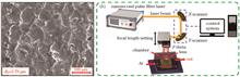
Objective In recent years, significant progress has been made in smart actuation devices; they have great potential for applications in microsurgery, cell manipulation, and biosensing. The majority of conventional actuators are mechatronic devices made of hard materials (e.g., metals, silicon, and silica) with low biocompatibility, softness, flexibility, and biodegradability, limiting their use in biomedical domains. Therefore, smart soft actuators made of soft and adaptive materials have significant advantages in this area. Biocompatible materials that can be directly applied to biomedical applications, such as cell manipulation and tissue sectioning, have significant advantages for future smart soft actuators. Thus, studying the treatment of biocompatible materials to create smart soft actuators critical for the development of intelligent micro-robots and micromechanical systems is crucial. In this paper, three-dimensional (3D) micromechanical structures based on biocompatible BSA (bovine serum albumin) material are directly written using the femtosecond laser two-photon polymerization technique. The femtosecond laser’s high 3D processing capabilities allow for 3D direct writing of the micro-nano devices’ external contours while modulating the properties of the materials inside the structure. The relationship between the degree of micromechanical expansion under external environmental stimulation and the bending angle, as well as the size of the mesh density, is examined using the design technique presented in this research. Furthermore, a 3D robotic arm model with capture and release capability is designed and fabricated. In the future, this design approach will has numerous applications in biomedical engineering, optical systems, micromechanical systems, and other domains.Methods In this study, BSA serves as the monomer, and MB (methylene blue) serves as the photoinitiator for the experiments. To make a viscous protein hydrogel, 500 mg/mL BSA and 0.6 mg/mL MB were dissolved in ultrapure water (18.2 MΩ·cm, 25 ℃). The prepared gels were then incubated at 4 ℃ for 24 h in a dark box to completely dissolve the constituent components. A homemade femtosecond laser two-photon polymerization processing equipment was used to obtain the BSA microstructures. For the fabrication, 20 μL BSA hydrogel was charged into a glass substrate, and a PDMS (polydimethylsiloxane) cavity was used to limit the evaporation of water in the gel. A Ti:sapphire femtosecond laser oscillator (Spectra-Physics 3960-X1BB) with a central wavelength of 800 nm, a pulse width of 120 fs, and an 80 MHz repetition rate generate the laser beam. A 60× oil immersion objective is employed to concentrate the femtosecond laser closely into the hydrogel for point-by-point 3D scanning. Before employing the objective, 20 mW-average laser power was measured, and the exposure duration for each voxel was 1000 μs. The samples were thoroughly rinsed in ultrapure water for few minutes after fabrication to remove the unpolymerized hydrogel.Results and Discussions The swelling ratio of BSA micro-nano blocks increased as the scanning step length increased from 100 nm to 200 nm because of a decrease in the cross-linking density of the processed structures. In a pH 1 solution, the swelling ratio is about 1.9 when the step length is 200 nm, whereas in a pH 13 solution, the swelling ratio is 2.65. For a step length of 100 nm in an alkaline solution, the swelling ratio is 76.7% of a 200 nm step length fabricated structure. In this paper, femtosecond laser two-photon polymerization was used to fabricate three bilayer cantilever structures with different scan step length distributions of 50 nm/100 nm,50 nm/150 nm,and 50 nm/200 nm. According to the experimental results, the maximum rotation angle of the bilayer cantilever structure is 28° when the bilayer scanning step length is 50 nm/200 nm. As shown in Figure 5(b), the micro-machine was subsequently employed to capture a micro-nano rod structure with a width of 6 μm. When switched to the solution with pH 13, the micromechanical “arm” swells and “grip” the rod tightly. The “release” operation can be completed quickly by switching back to the pH 5 solution. The experiment can be repeated over and over again.Conclusions This work describes a method for fabricating micromechanical devices using pH-responsive materials with nonuniform internal lattice density. Here, 3D micro-nano devices with high precision can be flexibly designed and produced using a femtosecond laser two-photon polymerization technique. It is also demonstrated that soft smart micro-machine with selective and accurate trapping and releasing may be obtained utilizing this technique by investigating the pH-responsive characteristics of BSA biomaterials. The construction of smart micro-nano devices with extensive and unprecedented functionality can be easily accomplished due to the rapid development of novel fabrication techniques and functional materials. Such smart micro-machines produced from biocompatible protein materials will play an essential role in future applications such as biomedical detection, microcellular analysis, and bionanotechnology because of advanced laser integration technology.
Jul. 05, 2021Vol. 48 Issue 14 1402001 (2021)
Yanli Qin, Bohui Sun, Hao Zhang, Dingrui Ni, Bolü Xiao, and Zongyi Ma
Significance Aluminum alloys and aluminum matrix composites have been widely used in aerospace components such as fuselage skin materials, engines, fuel tanks, panels, brackets, and metal mirrors owing to their excellent physical and chemical properties such as good thermal conductivity, electrical conductivity, ductility, plasticity, corrosion resistance, and low density.Traditional methods for fabricating aluminum components, such as casting and extrusion, require the use of tools or dies to produce the parts. However, aluminum alloys used in such processes suffer from low as-cast strength and require long production cycles. Furthermore, forming complex structures using these materials is difficult and the wastage of materials is high. Such limitations prevent aluminum alloys from meeting the requirements of high efficiency and fast manufacturing technology in aerospace industry and the flexibility to produce complex precise structures. Driven by this urgent demand, innovative developments have been made in the additive manufacturing (AM) processing of aluminum alloys and their composites.Selective laser melting (SLM), a type of laser three-dimensional (3D) printing, is a layer-based AM technology used for manufacturing complex and customized structures from metal powders. The main advantages of this process over conventional manufacturing methods include highly flexible design, simple machining process, structural integration, high material utilization, and high mechanical properties of produced samples. SLM can be used to produce intricate parts that conventionally require a series of manufacturing processes. Moreover, this process can be cost-effective by reducing the costs of raw materials and time-effective by reducing the time required for design and manufacturing.Although commercial applications of AM have increased rapidly, few materials have been deemed suitable for SLM so far. Aluminum alloys show good weldability; however, such materials are typically difficult to process in the field of laser 3D printing compared with titanium and nickel alloys. Thus, they have limited processing applicability. Moreover, their inherent high laser reflectivity, high thermal conductivity, easy oxidation, and low density cause problems in the formation process such as high liquid viscosity, balling defect, and poor powder fluidity. Moreover, fabricating aluminum matrix composites using SLM is even more difficult owing to the additional particles used in the process.Recently, improvements in the technology and application of high-power fiber laser equipment as well as increasing research on aluminum alloys have led to numerous achievements in SLM aluminum alloys. However, because limited varieties of aluminum alloys and their composites, most SLM techniques are focused on Al-Si systems. Accordingly, most research must be conducted in this field to promote the wide application of SLM based on aluminum alloys and their composites.Progress Herein, improvements in the performance of SLM aluminum alloys and their application in the aerospace field were summarized. First, methods for improving the mechanical properties of the alloys by optimizing the SLM parameters were introduced and the best parameter range was determined using single tracks and molten pool morphology (Figs. 6 and 7). Among the processing parameters, the effects of laser scan speed and power have been widely studied. Then, the post-treatments of heating and surface remelting of SLM aluminum alloy parts were detailed. The post-treatment processes were found to considerably improve the elongation of the sample (Fig. 8). In addition, the results of previous research on the properties of AM aluminum alloys and their composites with particles were summarized in detail (Table 2). In particular, some researchers have determined that the mechanical properties of aluminum alloys can be effectively improved by adding reinforcing particles (Figs. 9 and 10). Finally, research progress in the field of aerospace in terms of SLM aluminum components, such as metal mirrors, antenna brackets, and aircraft engines, was discussed (Figs. 11--15).Conclusions and Prospects Rapid developments have been made recently in SLM technology. In particular, the SLM technology based on aluminum alloys has entered the practical stage, with the application of key components in the field of aerospace manufacturing. In addition, SLM based on these alloys and their composites is expected to transform from scientific research into production and manufacturing, showing broad application prospects. In the future, the SLM based on aluminum alloys and their composites in the aerospace field will continue to develop in the following directions. (1) The mechanical properties of SLM aluminum components can be improved through the reasonable optimization of preprocessing parameters, postprocessing, and surface treatment, as well as by adding reinforcements. (2) The use of these alloys and their composites in SLM can be further developed for various aerospace structural parts. (3) Further developments should be made in terms of SLM equipment with large sizes, multiple beams, intelligent digitalization, complex structure, and customization based on aluminum alloys.
Jun. 26, 2021Vol. 48 Issue 14 1402002 (2021)
Jianhua Yao, Jinbang Huang, Guanghao Wang, Dayong Min, and Liang Wang
Objective Wire electrical discharge machining (WEDM) is suitable for the cutting of various metal parts with irregular contours. Fast-speed WEDM has a lower cost and higher efficiency than lower-speed WEDM. However, the surface roughness after fast-speed WEDM is larger and generally up to Ra=3--6 μm. For the polishing of WEDM rough surface, the existing methods mainly include mechanical polishing, chemical polishing, and electropolishing, but they have the disadvantages of low efficiency, high manual strength, high environmental pollution, and difficulty in polishing irregular parts. Laser polishing (LP) is a new surface polishing technology, which emerged during the development of laser processing technology. It has many advantages, such as high efficiency, no pollution, selective polishing, and irregular surface polishing, thereby avoiding the disadvantages of the traditional polishing methods. Presently, research on the pulsed LP (PLP) high surface roughness and its mechanism is inadequate. In this study, the fast-speed WEDM high surface roughness of 316L stainless steel (SS) was polished with a pulsed laser; then, the surface topography before and after polishing was photographed using a microscope with a super depth of field (SDoF) by which the surface profile and roughness were measured. Finally, the evolution law of polished surface morphology and PLP mechanism under different pulse duration values and energy forms was analyzed.Methods The experimental material was 316L austenitic SS. Before the experiment, a high surface roughness was obtained using a DK77-30 CNC WEDM machine with up to 3.79 μm surface roughness. Then, the surface was polished with a master oscillator power amplifier (MOPA) nanosecond pulsed laser with 100 W maximum average power and 100 μm focused-spot diameter. To prevent the surface oxidation of the material, during the LP process, the workpiece was placed in an atmosphere protection box wherein high-purity Ar was continuously supplied with a 15 L/min gas flow rate. Finally, NIKON stereoscopic and Keyence VHX-5000 microscopes with SDoFs were used to, respectively, photograph and observe the macroscopic/microscopic morphologies of the polished surface. The TR-130A surface roughness tester was used to detect the surface roughness of the sample after polishing.Results and Discussions As shown in Fig. 4, the microscopic peaks reduced under different pulse duration values. With 10 ns pulse duration, more initial valleys remained [Fig. 3(a)], and the crater-like appearance did not disappear [Fig. 4(a)]. With 50 ns pulse duration, the number of residual valleys decreased, and only a few deep valleys remained [Fig. 3(b)]. With the subsequent increase in pulse duration, the morphology after polishing tended to be consistent [Fig. 3(c--f)], and the contour had no peak and valley but an approximately horizontal and slightly fluctuating line [Fig. 4(g)]. As shown in Fig. 5, different pulsed laser energy forms had different effects on the surface morphology. The peaks reduced under the “low frequency with high energy” energy form, and several valleys remained [Fig. 6(a)]. Under “high frequency with low energy” energy form, valley was filled and surface morphology was smooth [Fig. 6(d)].As shown in Fig. 7(a), the surface roughness decreased with the increase in pulse duration and was finally saturated (Ra=0.95 μm). However, the fluctuation in a wide range of the surface was difficult to be removed, preventing the roughness from further decrease. As shown in Fig.7(b), surface roughness gradually decreased with the energy form change from “low frequency with high energy” to “high frequency with low energy,” and the melting mechanism of “high frequency with low energy” had a more sustainable energy input and was more suitable for high surface roughness polishing. The gasification mechanism of “low frequency with high energy” was more suitable for low surface roughness polishing.To further explore the action mechanism of pulsed laser on microscopic peak and valley of high surface roughness, a single pass experiment was conducted with different energy forms, and the change in microscopic peak and valley in the laser action area was observed using a microscope with SDoF. The “low frequency with high energy” form had a better effect on smoothing low peaks and shallow valleys than deep valleys but lacked continuous heat input and melt flow to fill deep valleys (Fig. 8). The “high frequency with low energy” form has a better effect on smoothing the microsurface topography, with continuous heat input and long-time melt flow of the material, resulting in a smooth surface (Fig. 9).Conclusions In this study, a MOPA nanosecond pulsed laser with a wide range of adjustable pulse duration and repetition frequency was adopted to polish WEDM high roughness surface. The three-dimensional morphology, two-dimensional contour, and surface roughness of the polished surface under different pulse duration values and energy forms were analyzed. The following were observed.1) Keeping other laser parameters constant, the microscopic surface peaks reduced under different pulse duration values, whereas the valleys showed a trend of gradually being filled as the pulse duration increased, and the surface roughness decreased from the initial Ra=3.79 μm to 0.95 μm.2) Keeping other laser parameters constant, with the pulse energy form change from “low frequency with high energy” to “high frequency with low energy”, the surface vaporization acting trace gradually became shallower, the peaks reduced and valleys were gradually filled, and the surface roughness decreased from the initial Ra=3.79 μm to 1.37 μm.3) With different energy forms, when the polishing mode gradually changed from pulsed polishing to quasi-continuous polishing, the surface polishing mechanism evolved from the gasification melting parallel polishing to simple melting polishing, and melting polishing was more suitable for polishing high roughness surface.4) The main reason PLP could reduce the surface roughness was the smoothing effect of the narrow peaks on the surface. The macroscopic fluctuation of the initial high roughness surface could not be smooth, which limited the further decrease in roughness when the PLP used the high roughness surface.
Jul. 02, 2021Vol. 48 Issue 14 1402003 (2021)
Lucheng Ge, Zisong Zhao, Ningxia Liu, Yanpeng Liang, Jingtao Zhang, and Cunshan Wang
Objective In recent years, many advances have been made on TC4 alloys, which have received significant attention in the research field of laser additive manufacturing (LAM) owing to their high specific strength, excellent corrosion resistance, and good biocompatibility. However, these alloys have been fabricated without considering the specific characteristics of LAM technology. Consequently, several metallurgical defects, such as pores, inadequate fusion, and cracks, can easily be produced during the LAM process owing to their high metallurgical defect sensitivity. Moreover, metastable phases are often formed locally because of a combination of an alloy’s low structural stability and the layer-by-layer nature of the fabrication process. This, in turn, affects the uniformity of mechanical properties, which cannot be completely achieved by optimizing the LAM processing parameters. The main characteristic of the LAM process is that the alloy undergoes the entire process from melting to solidification within a very short time. To effectively control this process, the LAM alloys must possess not only high mechanical, chemical, and tribological properties but also good formability because good formability is associated with characteristics such as high liquid-state fluidity, weak defect sensitivity, and low microsegregation. Therefore, regulating the structure and properties of TC4 through alloying is of great significance. In this work, new alloys were designed based on a basic TC4 composition alloyed with different Al additions. Then, these new alloys were prepared by applying LAM on a TC4 substrate. In addition, a systematic study of the microstructure and properties of these alloys system was performed with the aim to comprehensively improve the mechanical, chemical, tribological, and forming properties of TC4 alloys through composition optimization.Methods Alloy design in this work was based on the compositional analysis of a TC4 alloy and the specific characteristics of LAM technology. Then, LAM was employed to fabricate the alloys on a TC4 alloy substrate. The microstructure of as-deposited alloys was investigated using X-ray diffraction (XRD), scanning electron microscopy (SEM), and transmission electron microscopy (TEM). The hardness of these alloys was measured using a Vickers hardness tester. Compressive tests were performed using a universal testing machine. Their tribological properties were evaluated using a wear tester. Further, their electrochemical behavior in an HCl solution was investigated using an electrochemical workstation and their surface roughness was examined using a laser scanning confocal microscope.Results and Discussions a) The microstructures of all as-deposited alloys exhibited the morphological characteristics of a basket weave, where a multitude of individual α-Ti laths were separated by a thin layer of retained β-Ti (Fig. 2). In these structures, the α-Ti content gradually increased with an increase in Al addition, whereas their size initially decreased with the increase in Al addition (mass fraction) to 1.5% and then increased. This is due to the stabilizing effect of Al on the α-Ti phase and the variation of solidification interval. Moreover, the c/a axial ratio of α-Ti phase gradually increased with the increase in Al addition, indicating that the Al substitution of the Ti atoms exhibits a preference to occur at the {1100} α-crystal plane. b) The hardness (Fig. 5) and strength (Table 2) increased with the increase in Al addition owing to the enhanced solution strengthening and increased α-Ti phase, while the ductility (Table 2) reached its highest value at 1.5% Al addition (mass fraction), resulting from the formation of the first α-Ti phase. c) Under dry sliding friction and wear conditions, the wear mechanism of the as-deposited alloys was abrasive wear (Fig. 9). By increasing the Al addition, both the antifriction property and wear resistance gradually increased because the increased hardness effectively enhanced the resistance to abrasive wear (Fig. 8). d) The corrosion surfaces of all the as-deposited alloys exhibited etched-structure characteristics owing to electrode corrosion between the α- and β-Ti phases (Fig. 11). The corrosion resistance initially increased with the Al addition up to 1.5% and then decreased. This is mainly attributed to the changes in the content and size of the α-Ti phase. e) The surface roughness initially decreased and then increased with the increase in Al addition. Its lowest value was obtained at 1.5% Al addition (Fig. 12). This is mainly due to the fluidity and wettability variation of the melted alloy.Conclusions The microstructures of as-deposited alloys with different Al additions exhibit a basket-weave morphology, where a multitude of individual α-Ti laths are separated by a thin layer of retained β-Ti. In these structures, the content of the α-Ti phase gradually increases with the increase in Al addition, whereas its size initially decreases and then increases. Its lowest value is obtained at 1.5% Al addition. Thus, the hardness, yield strength, and tribological properties of as-deposited alloys increase, while the ductility, corrosion resistance, and surface roughness reach their optimal values at 1.5% Al addition. These results suggest that as-deposited alloys with a 1.5% Al addition exhibit the best combination of mechanical, tribological, chemical, and forming properties, which are superior to those obtained from as-deposited TC4 alloys.
Jun. 26, 2021Vol. 48 Issue 14 1402004 (2021)
Xinlei Luo, Meihong Liu, Zhenhua Li, Huaiyang Li, and Jibiao Shen
Objective Heat-source models play a key role in the numerical simulation of the selective laser melting process. To examine the applicability of the double ellipsoid and Gaussian surface heat-source models on simulation, the temperature field of a single-pass selective laser melted 18Ni300 metal powder was calculated using the two heat-source models and compared with experimental data.Methods The ANSYS APDL commercial software was used to establish a three-dimensional finite element model and to simulate the temperature field of the selective laser melting process. The double ellipsoid and Gaussian surface heat-source models were defined and applied to an 18Ni300 metal powder. Single-pass selective laser melted 18Ni300 samples were fabricated using EOS M290 by applying different laser power levels and scanning speeds. The sample widths were measured using scanning electron microscopy to determine the width of molten pools. In the calculated temperature fields, the sizes of molten pools of the single-pass selective laser melted 18Ni300 were analyzed and compared with experimental results.Results and Discussions The shapes of the temperature field distribution calculated using the double ellipsoid and the Gaussian surface heat-source models are all ellipsoidal after applying a 210 W laser power and a 1000 mm/s scanning speed. However, their width, length, and trail calculated using the double ellipsoid heat-source model are larger than those calculated using the Gaussian surface heat-source model (Fig.3). This is due to the difference in the energy distribution of the two heat-source models. In the Gaussian surface heat-source model, the energy is distributed on the surface of the powder layer, whereas in the double ellipsoid heat-source model, the energy is distributed deep into the powder layer. Moreover, the maximum temperature calculated using the Gaussian surface heat-source model is much higher than that calculated using the double ellipsoid heat-source model. This indicates that the diffusion speed of heat through the powder layer is faster than that through the surrounding environment, resulting in a lower maximum calculated temperature of the molten pool surface using the double ellipsoid heat-source model.Along with the laser scanning, the peak temperature calculated using the double ellipsoid heat-source model is lower than that calculated using the Gaussian surface heat-source model and fluctuates significantly with a rising trend. In contrast, the peak temperature calculated using the Gaussian surface heat-source model is higher and fluctuates slightly with small variations (Fig.4).The sizes of the molten pools calculated by applying a 210 W laser power and a 1000 mm/s scanning speed using the two heat-source models show that the width of the molten pool calculated using the Gaussian surface heat-source model is larger than that calculated using the double ellipsoid heat-source model. In contrast, the length and depth of the molten pool calculated using the double ellipsoid heat-source model are larger than those calculated using the Gaussian surface heat-source model (Fig.5).However, under different processing parameters, the calculated sizes of the molten pools using the two models exhibit different trends. Although the calculated width and depth of the molten pool using the two heat-source models decrease as the scanning speed increases (for the same laser power), the decreasing trend of the results calculated using the Gaussian surface heat-source model is slower than that calculated using the double ellipsoid heat-source model(Fig.6). It is confirmed that the depth of the molten pool calculated using the double ellipsoid heat-source model is larger than that calculated using the Gaussian surface heat-source model. The width of the molten pool is not only related to the laser power and scanning speed, but also to the diffusion of the laser energy in the powder. Since the Gaussian surface heat-source model does not take into account the energy diffusion in the powder, the width of the molten pool calculated using the Gaussian surface heat-source model is smaller than that calculated using the double ellipsoid heat-source model when the scanning speed is low, but it is larger when the scanning speed is high. The scanning speed has an exponential rather than linear effect on the width and depth of the molten pool. As a result, the width and depth of the molten pools are not the same under the same laser energy density. The width and depth of the molten pools obtained using high laser power and high scanning speed are larger than those obtained using low laser power and low scanning speed, although the same laser energy density was used.The experimental results confirm that the simulation results obtained using the double ellipsoid heat-source model are more accurate and reliable than those obtained using the Gaussian surface heat-source model in the simulation of the 18Ni300 selective laser melting process(Fig.8).Conclusions The double ellipsoid heat-source model takes into account the laser energy diffusion in the powder, and its calculated-results accuracy is better than that of the Gaussian surface heat-source model in the simulation of the 18Ni300 selective laser melting process. Thus,the double ellipsoid heat-source can describe the temperature field evolution and moten pool size during the selective laser melting process better than the Gaussian surface heat-source model. The width of the molten pool is not only related to the laser power and scanning speed, but also to the laser energy diffusion in the powder. The effect of the scanning speed on the width and depth of the molten pool is nonlinear. Under the same laser energy density, the depth and width of the molten pool obtained using high laser power and high scanning speed are larger. The width calculated using the double ellipsoid heat-source model is in good agreement with the experimental data, thus providing a basis for the optimization of the selective laser melting process.
Jul. 02, 2021Vol. 48 Issue 14 1402005 (2021)
Zhiyong Zhu, Hui Chen, Yanlong Ma, Jujin Huang, and Xu Zhao
Objective As renewable, low-cost, and pollution-free energy, hydroelectric power has become crucial in the world energy structure due to increasing tensions with traditional nonrenewable energy. Hydropower stations in China have been rapidly developing in recent years. To meet the needs of hydropower stations, hydropower steel has gradually developed from 600 MPa and 800 MPa to 1000 MPa for a further reduction of the weight and wall thickness of pressure steel tubes, improvement in the welding performance of welded joints, and a reduction of the comprehensive cost of the project. Even with continuous improvements in high-strength steel, problems such as welding cracks, heat-affected zone softening, and welding pores are still prone to occur during the welding process, which impedes the popularization and application of high-strength steel. Traditional welding methods have a high welding heat input that result in a wider welding heat-affected zone and large residual stress after welding, which significantly diminishes the mechanical properties of the joints. However, the laser-MAG hybrid method is appropriate for high-strength steel welding due to low heat input, large weld depth-to-width ratio, minimal post-weld deformation, and low residual stress. Therefore, it is important to study the properties of laser-MAG hybrid welding joint of B950CF high-strength steel for its application in the field of hydropower.Methods In this study, pulsed laser-MAG hybrid and laser-MAG hybrid welding are used for the butt welding of B950CF high-strength steel for better comprehensive mechanical properties. The welding equipment consisted of a TRUMPF LASER TruDisk 10002 fiber laser and a Fronius welding machine. The laser-guided hybrid welding method was implemented in this study. In addition, a Y-shaped groove was utilized, and the butt gap was 1.2 mm. The optimal process parameters for the welding methods were obtained through a single factor control variable method. The microstructure and fatigue fracture morphology of the welded joints was observed through a SEM QUANTA FEG250 scanning electron microscope. The hardness and tensile of the joints were tested by a Vickers hardness tester and a electronic universal tensile testing machine. The fatigue test was completed on a QGB-100 microcomputer controlled high-frequency fatigue testing machine. The stress ratio R(σmin/σmax) was 0.1, and the number of cycles was set to 10 7. Results and Discussions This study indicates that both welding methods obtain joints with good forming performance. However, the addition of a pulsed laser results in the decrease of the width of weld seam and heat-affected zone (Fig. 4). Both welded joints consist of a weld zone, coarse-grain heat-affected zone, fine-grain heat-affected zone, and non-full transformation zone. The weld microstructure of the methods comprises lath martensite, bainite, and small quantities of residual austenite. Specifically, the coarse-grain zone microstructure is lath martensite, the fine-grain zone microstructure consists of fine martensite and bainite, and the microstructure of non-full transformation zone consists of bainite with small quantities of martensite. Using a pulsed laser, the line energy is minimal, the cooling speed is fast, the residence time of the weld and the heat-affected zone at high temperatures is short, and the growth of crystal grains is inhibited. Furthermore, the pulsed laser has a stirring effect on the molten pool, which increases the rate of heat dissipation of the metal in the molten pool. This creates a uniform molten pool temperature and further inhibits the growth of crystal grains, causing a finer crystal grain than that of the continuous laser, thereby improving the performance of the welded joint (Figs. 6 and 7). Additionally, the average fatigue S-N curve of pulsed laser-MAG hybrid welded joints is higher than that of laser-MAG hybrid welded joints, with a better fatigue life under all stress levels (Fig. 10). These advantages when utilizing the pulsed laser-MAG hybrid welding method occur because the fatigue source pores and the stress concentration around the pores are small, so the crack initiation life is increased. Further, there are more interlaced bainite laths in the weld zone, which hinders crack propagation and improves crack propagation life.Conclusions In this study, the comparison of the microstructure and properties of the welded joints obtained by two welding methods provided the following interpretations. Compared with laser-MAG hybrid welding, pulsed laser-MAG hybrid welding has no clear difference in microstructure except for smaller crystal grains. The average hardness of the weld zone is 1.24 and 1.18 times higher than the base metal hardness (320 HV), with the highest value appearing in the fine-grain HAZ. The fracture positions of the tensile specimens for the two joints are in the base material. The average fatigue strength (Nf=10 7) of the pulsed laser-MAG hybrid welding joints is 311 MPa that is 22 MPa or approximately 7.6% higher than the laser-MAG hybrid welding joints (289 MPa). The small fatigue source pores and disorderly distribution of the weld zone's microstructure increase the fatigue crack initiation life and crack propagation life, respectively. These factors are the primary reason that the fatigue life of the smooth joint from pulsed laser-MAG hybrid welding of B950CF high-strength steel is higher than that of laser-MAG hybrid welding. In conclusion, it is observed that pulsed laser-MAG hybrid welding can improve the performance of the welded joint for B950CF high-strength steel.
Jun. 26, 2021Vol. 48 Issue 14 1402006 (2021)
Suming Chen, An'an Zhao, Yi Jiang, Ting Liu, Tingyan Yan, and Xiaohong Zhan
Objective TC4 titanium alloy (Ti-6Al-4V) is widely used in aerospace, petrochemical, shipbuilding, and automobile fields because of its excellent performance in specific strength, corrosion resistance, and thermal strength. It is an important new structural material. The traditional welding technology of titanium alloy is argon-arc welding technology. Arc welding has great convenience in welding operation and observation. It can be employed to weld several materials. However, it has some unavoidable disadvantages, such as large welding heat-affected zone, large welding stress, and deformation after welding. Moreover, laser welding technology has the advantages of high energy density, narrow heat-affected zone, and small deformation after welding. It can obtain high-quality welded joints to meet the requirements. At present, laser self-melt welding is a common laser welding technique; however, it can easily cause depression on the surface of the weld seam, welding leakage, and other problems due to the lack of filler wire. Therefore, its application in aerospace field with high requirements for weld forming has limitations. In this study, the laser wire filling welding experiment of thin Ti-6Al-4V with a thickness of 1.2 mm was performed, and the influence of the process parameters on weld seam forming was studied. Finally, an optimized process parameter combination with a small clamping gap was obtained. This study is an effective supplement and new exploration of traditional thin plate laser welding without filler wire. It is highly consistent with the long life and airworthiness requirements of aircraft. In addition, it has distinct innovation and application value.Methods The base metal adopted in this laser wire filling welding experiment is Ti-6Al-4V with a thickness of 1.2 mm; the filler wire used is Ti-6Al-4V filler wire with the same composition as the base metal. The laser generator used is TruDisk 12003 disc laser generator with a maximum power of up to 12000 W, and the KR60HA robot is a high-precision robot specially developed for laser welding by KUKA company of Germany.Results and Discussions When the welding speed is 1.5 m/min, the wire-feeding speed is 1.5 m/min, and only the laser power changed in the experiment. The continuity of the front and back of the weld seam is poor when the laser power is 1.3 kW. The reason is that the welding speed is too fast, and the laser energy input cannot melt enough filler wire to form a continuous weld seam. However, when the laser power increased to 1.5 kW, weld leakage occurs, which is related to the mismatch of welding speed and wire-feeding speed (Fig. 2). Then, the welding speed is reduced from 1.5 m/min to 1.2 m/min, and the laser power is maintained. At this time, there is no welding leakage, the whole forming is better, but the continuity is still poor. It is due to the wire-feeding speed is slow, and the amount of molten filler wire is not enough to fill the gap, so the continuous and beautiful weld seam cannot be formed in the welding process (Fig. 3). Keep laser power 1.5 kW and welding speed 1.2 m/min unchanged, only change wire-feeding speed. When the wire-feeding speed is reduced to 1.3 m/min, the weld seam formation is poor, and there are a large number of welding leakage positions. With the increase of wire-feeding speed, the weld forming obviously improved. When the wire-feeding speed is 2.5 m/min, the weld seam is saturated and beautiful, and the continuity is good (Fig. 4).Conclusions The results show that suitable choice and matches of process parameters play a significant role in obtaining high-quality joints during laser wire filling welding of Ti-6Al-4V with a thickness of 1.2 mm. If the welding speed does not match with the wire-feeding speed, the welding wire has insufficient time to melt and form a continuous and beautiful weld seam, which can easily cause a welding leakage problem. In addition, the wire-feeding speed should also match the laser power. When the laser power is too small, the heat input is less; and when the wire-feeding speed is too slow, the amount of filler wire fed is less, which will cause an insufficient amount of molten filler wire and can easily cause poor continuity of weld seam. Moreover, the selection of assembly clearance size will affect the formation of appearance defects such as welding leakage and discontinuous weld seam. The optimized process parameters obtained in this paper is suitable for the situation when the assembly clearance size is large. When the assembly clearance changes, the process parameters should be adjusted appropriately according to the specific situation. In this paper, when the laser power is 1.5 kW, the welding speed and wire-feeding speed are 1.2 m/min and 2.5 m/min, respectively, the weld seam has satisfactory macroformation, the appearance of the weld seam is continuous and uniform, and there are no obvious appearance defects such as undercut, weld bead, and weld leakage.
Jun. 26, 2021Vol. 48 Issue 14 1402007 (2021)
Zhenghao Zhang, Chuanqiang Wang, Enyu Qi, Yunlong Li, and Shikai Wu
Objective High silicon titanium-containing austenitic stainless steel is used as shell material in nuclear reactor fuel components due to its excellent radiation resistance and high-temperature mechanical properties. By adjusting element content based on 316 stainless steel, 1515 stainless steel improved service performance and became the third-generation shell material of the fast neutron reactor fuel component. Welding is an essential method for building shell components during manufacturing. For the welding of 1515 stainless steel, the traditional arc welding method is prone to defects, such as thermal cracks, intergranular corrosion, and joint embrittlement, and porosity defects of laser-welding lead to failure risks during service conditions, especially for incomplete penetration jointing. Thus, decreasing welding defects of shell components and obtaining welding joints, which meet technical requirements, are the main task for the welding of 1515 stainless steel. In this study, shell components are welded using the laser-arc hybrid welding method. By process optimized, welded joints without pores, cracks, and other defects, and mechanical properties met technical requirements of a nuclear reactor.Methods In this study, 1515 stainless steel with backing plate is welded using the laser-arc hybrid welding method. First, the welding orthogonal test is designed based on the preliminary process exploration, and optimized welding parameters are obtained. The quantity and distribution of pores in welded joint are detected by radiographic testing(RT) ray detection and the influence of laser power; welding speed and defocus on the porosity of the weld joint are investigated. Second, the microstructure of the welded joint is observed using the optical microscope and mechanical properties of tensile. Besides, bending and hardness are tested. Finally, the tensile fracture section is observed through a scanning electron microscope.Results and Discussions Welding speed and defocus have a strong influence on the porosity of the welded joint. Increasing welding speed and defocus can significantly reduce porosity when the laser power and arc current remained even welded joints with almost no porosity can be obtained (Table 2) under laser power 3.0 kW, arc current 130 A, welding speed 1.8 m/min, and defocus +20 mm. The overall shape of the welded joint cross section is wide at the top and narrow at the bottom. The weld grains gradually decreased from top to bottom. This is due to the higher heat input on the upper part of the welded joint than its lower part. However, the welded joint consists of the weld zone, fusion line, and heat-affected zone. The microstructure of the weld zone is single austenite. There are many thick columnar crystals in the center of the weld zone, and the crystal growth direction is along the direction perpendicular to the fusion line. The grain size of the weld zone near the fusion line is reduced, and there are small equiaxed and cellular crystals. The microstructure of the heat-affected zone is the same as that of the base material; however, the grain size is slightly larger than the base material (Fig. 4) due to the welding heat input. In the tensile test of the welded joint, the tensile strength is (607±12)MPa, which is about 73% of the tensile strength of the base material. It meets the requirement of the nuclear reactor for the welded joint tensile strength of the shell material (≥520 MPa). The average elongation of the joint after fracture is 6.5%. The tensile fracture position is at the center of the weld (Fig. 5). Besides, the surface of the tensile fracture is covered with a large number of tear edges and small dimples (Fig. 6), indicating that the fracture of the welded joint is a typical ductile fracture. In the bending test, no cracks are found on the surface and root of the weld (Fig. 7) after 180° face and back bending of the welded joints. Besides, the hardness of the weld zone is 160 HV0.1, which is lower than other areas of the welding joint, and is about 60% of the hardness of the base material. The hardness of the heat-affected zone is between the weld zone and base metal (Fig. 8).Conclusions With the optimal parameters, the laser-arc hybrid welding of high silicon titanium-containing austenitic stainless steel is completed, and well-formed welded joints are obtained. By increasing the welding speed and defocus, the porosity of the weld can be significantly reduced. Besides, welded joints with almost no porosity can be obtained under laser power of 3.0 kW, arc current 130 A, welding speed 1.8 m/min, and defocus +20 mm. The welded joint consists of the weld, fusion, and heat-affected zones. The microstructure of the weld zone is single austenite, and the grain size gradually decreases from top to bottom on the cross section. The microstructure of the heat-affected zone is the same as that of the base material; however, the grain size is slightly larger than that of the base material. The average tensile strength of the welded joint is 607 MPa, which is about 73% of the tensile strength of the base material, and the average elongation after fracture is 6.5%. There are many tear edges and dimples in the tensile fracture, which is a typical ductile fracture. The hardness of the weld is 160 HV0.1, which is about 60% of the hardness of the base material. The results of 180° face and back bends are qualified. It means that joint mechanical properties meet the technical requirements for shell material in nuclear reactors.
Jul. 05, 2021Vol. 48 Issue 14 1402008 (2021)
Evolution Mechanism of Powder Properties of Recycled 316L Stainless Steel in Selective Laser Melting
Chao Lu, Mengzhi Xiao, Yuebo Qu, Yan Yin, and Ruihua Zhang
Objective The interaction between laser and powder particles has a significant influence on the characteristics of the powders during the selective laser melting (SLM) process. However, the understanding of the transformation and evolution mechanism of the recycled powder in SLM is limited. The physical and chemical properties of powder change significantly with the increase in powder recycling times in the SLM process. Nevertheless, research on the variation of powder properties with the increase in recycling times is inadequate. Some researchers have studied the recycling of 316L stainless steel (SS), Ti6Al4V, AlSi10Mg, and CoCr alloy powders, but no consistent regulation has been obtained owing to the differences in recycling methods, forming equipment, forming processes, and the number of uses. The 316L SS powder is a widely used material owing to excellent corrosion resistance and good weldability. Therefore, studying the variation regulation of 316L SS powder characteristics with the increase in SLM recycling times is necessary to understand the variation and oxidation mechanism of the recycled powder, which helps to elucidate the reason for the unstable quality of SLM parts. The findings of this study can help understand the evolution of powder characteristics during the 316L SS powder recycling process better, judge recycling characteristics, and develop recycling standards. The study method is also applicable to other powder bed melting additive manufacturing technologies.Methods The raw material selected was 20 kg 316L SS powder. In the early SLM experiment and small-batch processing, argon (Ar) with a purity of 99.99% was continuously filled to keep the oxygen (O2) content in the forming chamber below 5×10 -4(volume fraction) to prevent material oxidation during the forming process. After each test or production, the SS powder was strictly screened and then dried to remove water vapor. Some dried SS powder was taken as the sample for detection and analysis, and the physical and chemical characteristics were analyzed. The characteristics of the SS powder, such as particle size distribution, bulk density, tap density, fluidity, morphology, composition, O2 content, and surface microstructure, were comprehensively studied. No new powder was added to the sample powder during recycling. The particle size, physical properties, surface morphology, microstructure, and element content of SLM recycled powder were analyzed using a laser particle size analyzer, physical property tester, scanning electron microscope, and energy dispersive spectrometer. Results and Discussions The proportion of fine and coarse SS powders, respectively, decreases and increases with increase in SLM recycling times, indicating that the particle size distribution of the SLM recycled powder was coarser and more concentrated. Owing to the formation of irregular coarse particles inducing more voids and bridging between the stacked powders, the bulk and tap densities of the recycled powders showed decreasing trends, and fluidity improved. The recycled powder had more irregular, sintered, broken, rod-shaped, and spherical particles than the virgin powder, which is owing to laser-powder-molten pool interaction. Large size powder particles with black circular spots on the surface were found in the powder that was recycled many times. EDS analysis showed that the circular oxidation spots were rich in silicon (Si) and manganese (Mn). The formation of circular spots on the surface of large particles was closely related to O affinity, high-temperature diffusion rate, and O2 partial pressure. The surface microstructure of the powder gradually changed from coarse dendrites to cellular crystals owing to the thermal radiation of the laser. In this study, the irregular particles in the recycled powders were divided into two categories: laser-induced melt ejection particles and gas entrainment-induced irregular particles. The different formation mechanisms of these two types of irregular particles were discussed in detail, respectively. The weak magnetic particles of 316L austenitic SS powders produced by phase transformation in SLM were also revealed.Conclusions The D90 and D10 of 316L SS powder increased by 14.5% and 26.5%, respectively, after 30 recycling times in SLM. The particle size distribution of the powder coarsens with the increase in recycling times, with more rod-shaped, broken, and irregular particles in the recycled powder. The oxidation spots formed on the surface of spherical particles with larger diameters were rich in Si and Mn. The formation mechanism of oxidation spots was mainly determined by element type, O affinity, high-temperature diffusion rate, and oxidation potential. Dendrite content in the surface microstructure of the recycled powders significantly reduced. The irregular particles in the recycled powders were divided into two categories: laser-induced melt ejection particles and gas entrainment- induced irregular particles. The formation mechanisms of the two irregular particle categories were related to the molten pool instability and Ar vortex, respectively. The recycled powders also exhibited weak magnetism owing to recrystallization.
Jul. 02, 2021Vol. 48 Issue 14 1402009 (2021)
Jiajie Han, Jianping Zhou, Ruilei Xue, Yan Xu, and Hongsheng Liu
Objective At present, pipeline automatic welding is generally equipped with a structural light sensor for seam tracking. And the detection of welding quality is one of the key points in robotic welding. Therefore, it has great practical value for the research on the detection of welding quality monitored by a linear structured light sensor. However, the existing weld forming quality detection based on structured light is mostly carried out on each contour line, and the change of adjacent contour lines is not properly utilized. For pipeline welds, it is difficult to guarantee the interval of adjacent contour lines when reconstructing the three-dimensional (3D) morphology of the weld surface by line structured light scanning. The weld edge, width and reinforcement extracted from each single contour also exist deviations due to the positioning error of the detection platform. Aiming at these problems, this paper presents a weld forming quality inspection method based on 3D reconstruction. And we hope that our findings can be helpful for pipeline automatic welding production.Methods In order to improve the speed of extracting central-lines from structured light, the region of interest (ROI) should be extracted from the first and the last frames of the original N-frame images. Then the ROI is corrected by random sampling to ensure that the feature region is always within the ROI in the acquisition process. After Gaussian filtering, median filtering, image binarization, and morphological processing, the edge of structured light is extracted by the Laplace operator, and the sub-pixel centerline of structured light is obtained by the gray centroid method. Then the average value of each column is taken as the actual centerline position (Fig. 3). To calculate the deviation between the axis of the pipeline to be measured and the rotation center of the profiler, the feature points of each central-line are extracted by calculating the changing rate and piecewise fitting, according to the measured results of the profilometer in both the horizontal and vertical states. After position and attitude of the platform are corrected, the information on weld surface is obtained. The 3D morphology of the pipeline weld surface is reconstructed by numerical calculation and point cloud processing. Aiming at the point cloud outliers, the filtering algorithm is improved by setting the height threshold and the outliers are reset according to the formulas (8) and (9). In order to facilitate the follow-up process, the circular seam is treated as a plane in the 3D reconstruction. After the base metal plane is fitted by the improved least squares algorithm, the weld edge is extracted by calculating the deviation and removing the contour in which weld width is greater than W and smaller than W-2v where W is ideal weld width and v is weld broadening. The central-line of weld is fitted according to the median value of the left and right weld toe coordinates. Then it is moved along the base metal plane to obtain the allowable boundary of the weld edge. Finally, the idealized model is established according to the width and reinforcement of seams to detect the weld forming quality and to identify the defects, such as excessive weld metals, undercut, lack of fusion (Fig. 13).Results and Discussions The difficult problem of contour stitching can be solved in the reconstruction of the pipeline weld surface based on line structure light by correcting the position-posture of the platform and perfecting the detection process. The closer the fitting parameters of the left and right base metal surfaces of the pipeline are, the better the butt joint will be. Compared with that of the weld edge extraction from each contour, the distribution of weld toe extracted from the 3D reconstruction model is closer to the same plane and more accurate (Fig. 12). The closer the actual weld surface contour is to the ideal model, the better the weld forming quality will be (Tables 1 and 2). When the weld edge is located within the maximum and minimum boundaries and the actual height is lower than the minimum surface height of the idealized model, it is undercut. In the weld zone, the actual height is larger than the maximum surface height of the idealized model, means over reinforcement (Fig. 14). At the same time, it should be noted that after repeated filtering of the data, the abnormal points caused by small cracks and porosity or other defects on the weld surface are also removed, making them almost impossible to detect. Detection of weld defects according to the spatial threshold, such as crater, spatter, and overlap, should be further studied.Conclusions Idealized model established based on the measured results of 3D reconstruction of pipeline weld surfaces can be used to make a general assessment of the weld surface forming quality and identify reinforcement, undercut, etc. Compared with that based on the contour of each frame, forming quality measured based on the reconstruction results performs better.
Jun. 26, 2021Vol. 48 Issue 14 1402010 (2021)
Yanan Liu, Mi Gu, Ronglu Sun, Yupei Zhao, Yujun Zhu, and Xuejiao Yang
Objective Titanium alloys have low density, high specific strength, and excellent corrosion resistance, thus they are commonly used in the engineering field to improve the mechanical properties of structural parts. However, their usage for various industrial applications is severely constrained owing to low hardness and poor wear properties. Several critical studies have been conducted regarding the surface modification of titanium alloys to solve their defects, including thermal spray, ion implantation, vapor deposition, and laser cladding, which have effectively improved their mechanical properties. In this work, a laser cladding composite coating was prepared on the Ti811 surface using the coaxial powder feeding method to improve the micro-hardness and wear resistance of the Ti811 alloy. The coating microstructure was characterized to study its phase compositions and elemental distribution. Moreover, the micro-hardness, friction, and wear properties of the coating were tested, and the CeO2 dispersive strengthening mechanism in the coating was revealed. The research results here can provide a valuable experimental and analysis basis for studying the laser cladding of composite coatings on Ti811 alloys.Methods The TruLaser Cell 7040 laser-processing center with a 4 kW laser at a 1030 nm wavelength was used for the laser cladding process. The coaxial powder feeding laser cladding technology was developed to synthesize the TiC/Ti2Ni composite coating. The laser process parameters are as follows: laser power of 900 W, scanning speed of 400 mm/min, powder feeding speed of 5.0 g/min, protective gas flow of 11 L/min, powder feeding gas flow of 7 L/min, spot diameter of 3 mm, and working distance of 16 mm. The chemical compositions(mass fractions)of the materials used for laser cladding are Ni60(74%),TC4(20%),NiCr-Cr3C2(5%),and CeO2(1%). A Ti811 (Ti-8Al-1Mo-1V) cuboid specimen of 40 mm× 30 mm × 8 mm was used as the substrate material. The chemical compositions (mass fractions) of the substrate are Al(8.1%), Mo(1.05%), V(0.99%), Fe(0.05%), C(0.03%), N(0.01%), O(0.06%), and Ti (Bal.). Before laser cladding, the working surfaces of the specimens were sandblasted to remove the oxide skin and cleaned in absolute ethanol using an ultrasonic cleaner for 20 min. The specimens were then cut off along the section of the coating via wire cut electrical discharge machining into a size of 15 mm×7 mm×8 mm as the metallographic samples. A mixture of HF, HNO3, and H2O was used as the etchant. The etching time was 10--25 s. The precipitation order of the phases was predicted using thermodynamic calculation. X-ray diffraction, scanning electron microscope (SEM), field emission electron probe (EPMA), Vickers hardness, friction, and wear testers were used to analyze and study the phase compositions, microstructures, elemental distributions, micro-hardness, and wear resistance of the coating.Results and Discussions The composition analysis showed that the final phase mainly consisted of ceramic-reinforced phase TiC and TiB2, intermetallic compound Ti2Ni, and α-Ti solid solution. The thermodynamic calculation revealed a precipitation order of TiB2→TiC→Ti2Ni→α-Ti (Fig. 4). The SEM analysis and the EPMA results showed that TiC had a petal shape, TiB2 had a long rod shape, Ti2Ni had a strip shape, and nano-CeO2 was dispersed in the coating (Figs. 5 and 7). The micro-hardness improvement was mainly attributed to the effect of fine grain strengthening, dispersion strengthening, and solution strengthening. The highest micro-hardness of the coating was 902 HV, 2.37 times that of the Ti811 substrate (Fig. 8). The wear volume of the coating was reduced by 27.9% compared with that of the substrate. The friction coefficient was stable between 0.38 and 0.42. The wear mechanism was mainly adhesive and slight abrasive wear with an excellent wear resistance (Figs. 9 and 10).Conclusions In this study, an in-situ TiC/Ti2Ni composite coating was prepared on Ti811 alloy using the coaxial powder feeding laser cladding technology. The final phase of the coating mainly consists of ceramic-reinforced TiC and TiB2, intermetallic compound Ti2Ni, and α-Ti solid solution. The precipitation order of this phase was TiB2→TiC→Ti2Ni→α-Ti. The improvement in the coating micro-hardness was mainly attributed to the dispersion strengthening effects of TiC, TiB2, Ti2Ni, and nano-CeO2, and the solid solution strengthening effect of α-Ti. The highest coating micro-hardness was 902 HV, which is approximately 2.37 times that of the Ti811 alloy. The wear volume of the coating was approximately 27.9% less than that of the substrate. The friction coefficient of the coating was stable between 0.38 and 0.42. The wear mechanism of the coating was dominated by adhesive wear and slight abrasive wear with excellent wear resistance.
Jun. 26, 2021Vol. 48 Issue 14 1402011 (2021)
Xianpeng Gao, Junqiang Xu, Qi Zhou, Xusheng Qian, Zixiong Lin, and Minglang Zhang
Objective The Ti6Al4V titanium alloy exhibits specific advantages such as low density, high specific strength, good corrosion resistance, and strong biocompatibility. Its potential applications cover a wide range of technological fields, including aerospace, automobile manufacturing, shipbuilding, biomedicine, national defense, and military industry. However, its poor wear resistance and low hardness have restricted its application in industry. In recent years, particle-reinforced titanium-based composite materials have been fabricated by introducing second-phase particles into the titanium and titanium alloy matrix. These materials are expected to improve the hardness and overall performance of the matrix. Ceramic-reinforced titanium-based composite materials are one of the particle-reinforced titanium-based composite materials. Compared with traditional titanium alloy materials, the hardness, wear resistance, and some mechanical properties of the ceramic-reinforced titanium-based composite materials can be improved by adding reinforcing phases. Among all ceramic materials, B and C in B4C have a strong affinity for Ti. During the laser high-energy-density melting process, in situ reaction between Ti and B4C may occur, resulting in the production of TiB, TiB2, TiC, and other high-hardness, high-thermal stability compounds. Compared with other forming methods, the selective laser melting technology, which is an additive-type method, is applied to directly shape metal components after laying a powder bed. The advantage of this technology is the laser high-energy density, which can promote generation of an in situ reaction between powders. Using this technology, shape control and the control of complex structural parts can be achieved.Methods Ti6Al4V-10%B4C composites were prepared using selective laser melting technology. First, the surface roughness and relative density of the composites were investigated by applying different laser energy densities (58.33, 66.67, 75, 87.5, 100, and 114.3 J/mm 3). Then, the degree of the in situ reaction between Ti and B4C and the composition of the reactants were investigated. The form of existence of the reinforcing phase in the composite materials and its effect on the microstructure of Ti6Al4V titanium alloy matrix were also analyzed. In addition, the microhardness of the Ti6Al4V-10%B4C composites was tested and the effect of the B4C addition on the hardness of the Ti6Al4V titanium alloy matrix was analyzed. Results and Discussions During the forming process of the Ti6Al4V-10%B4C composites, an in situ formation reaction between Ti and B4C occurred, and the reactants were TiB2 and TiC. These reactants can be considered reinforcing phases that refine the Ti6Al4V titanium alloy matrix grain and considerably improve the hardness of the Ti6Al4V titanium alloy matrix. The surface roughness and relative density of the Ti6Al4V-10%B4C composites prepared under different laser energy densities were compared. When the laser energy was too high or too low, the forming surface of the composite material exhibited an apparent spheroidization, resulting in an increase in the surface roughness of the composite material. High surface roughness indicates bad forming quality of the next layer, which results in a decrease in the density of the composite material (Fig. 4). An analysis of the phase composition and microstructure morphology of the composite material revealed that the phase compositions of the composite material were mainly α-Ti, β-Ti, TiB2and TiC, indicating that an in situ formation reaction occurred between Ti and B4C. The TiB2 and TiC existed in the Ti6Al4V titanium alloy matrix mainly in clustered or reticular associated organization (Fig. 7), which significantly refined the Ti6Al4V titanium alloy grain (Fig. 8). Microhardness testing of the Ti6Al4V-10%B4C composites showed that the addition of B4C could significantly improve the hardness of the Ti6Al4V titanium alloy. For laser energy density of 114.3 J/mm 3, the microhardness of the composite material could reach up to 910 HV (Fig. 9). This is a 153.5% enhancement compared with pure Ti6Al4V titanium alloy matrix. Conclusions In the present study, Ti6Al4V-10%B4C composites were successfully prepared using selective laser melting technology. TiB2 and TiC were generated in situ from Ti and B4C. These enhanced phases significantly refined the grains of the Ti6Al4V matrix and enhanced its microhardness. A comparison of the forming surface roughness and the relative density of the Ti6Al4V-10%B4C composite materials prepared under different laser energy densities revealed that for a laser energy density of 66.67 J/mm 3, the surface roughness of the composites exhibited its lowest value, the value of Ra was 37.2 μm, the value of Rz was 216 μm, and the relative density reached its highest value (95.55%). During the preparation of the Ti6Al4V-10%B4C composite via selective laser melting, an in situ formation reaction occurred between Ti and B4C, and the reactants were TiB2 and TiC. The grain size of TiB2 approached the nanometer level. The TiB2 and TiC reactants exhibited clustered or reticular associated TiB2-TiC organization. The microhardness of the Ti6Al4V-10%B4C composite material was significantly higher than that of a pure Ti6Al4V titanium alloy material and its highest microhardness value was 910 HV, which is 153.5% enhancement compared with the titanium alloy matrix.
Jul. 02, 2021Vol. 48 Issue 14 1402012 (2021)
Ming Zhu, Bo Wang, Buyun Yan, Qian Yang, Yu Shi, and Ding Fan
Objective Laser cladding technology is widely used in coating deposition, worn surface repairing, and direct fabrication due to advantages, such as high deposition accuracy, small heat-affected zone, metallurgical bonding, and minimal dilution with the substrate. It is a surface modification technology for thin coating/layer fabrication with improved surface properties or surface defect refurbishment by forming highly resistant gradient coatings/layers on a substrate. Recently, the innovations in diode laser cladding significantly support remanufacture, and more stringent requirements have been put forward on the forming accuracy and quality. There is inadequate research on forming mechanisms in the diode laser cladding process; just depending on numerous process tests or human experience cannot effectively improve accuracy or control quality under unfavorable conditions, such as heat accumulation and stress concentration. To improve the laser cladding technology level, the development of on-line and high-speed monitoring and process controlling system is necessary. In particular, studies on powder melting behavior play a paramount role in forming mechanisms. Therefore, for fore-put powders, the characteristic behavior of the melting process was detected, and the investigation of the thermal physical characteristics was analyzed. Then, the equations of heat balance to describe the melting process were established. Finally, a model to analyze the thermal physical process in diode laser cladding process was set up.Methods To analyze the interaction process between the diode laser and fore-put powders, first, an optical acquisition system with a high-speed camera was set up to observe the powder melting process; second, based on the analysis of the collected high-speed camera data, the characteristic behavior of the cladding process was analyzed; and finally, according to the analysis of the powder melting process, the models of thermophysical processes in different characteristic stages were set up, and the heat-balance equation for each characteristic stage was established.Results and Discussions There are typical physical phenomena in the powder melting process, starting from the laser irradiation of the powder layer to the formation of the cladding layer (Fig. 4). The cladding process can be divided into four stages according to the existing physical phenomena (Fig. 5). 1) Initial stage: under the laser heat source radiation, the powder particles adhere to each other and gather to form particle agglomerates. 2) Melting stage one: the powder particles are melted to form liquid metal pellets with sizes of 1.27--1.90 mm. 3) Melting stage two: the liquid metal pellets agglomerate to form a larger liquid metal ball with a diameter of 3.80--7.25 mm, surrounded by a few liquid metal pellets with diameters of Conclusions In this study, the melting process of fore-put powders was detected by a high-speed camera and divided into four typical stages. Based on the influence of laser irradiation on the duration of each characteristic stage, the duration of each of characteristic behavior ①, ②, and ③ increased under the same laser irradiation. This result shows that the transformation of the powders from solid to liquid droplets does not require much energy; however, to realize the movement, convergence, and fusion penetration of the liquid droplets, certain laser energy is required. The process is slow with a lower laser power, which affects the spread of the liquid droplets and forming morphology. A thermophysical model that can describe the dynamic thermal interaction behavior between the laser and fore-put powders has been established. Through the analysis of the model, the thermophysical interaction behavior at different characteristic stages can be explained. According to the analysis of the powder melting process, when the laser power increases or the defocus amount decreases, the rate at which the powder melts increases, and numerous liquid metal drops are formed. The diameter of the liquid metal drops and spread rate increases. As the radius of solid powder particles decreases or the reflectivity of liquid metal drops, the duration of ① and ② reduces; also, the wetting angle decreases, and the spreading performance improves.
Jul. 02, 2021Vol. 48 Issue 14 1402013 (2021)
Yan Yin, Kaiji Dong, Zhiheng Li, Zhihui Li, Xutian Chai, and Ruihua Zhang
Objective Recently, with the continuous development of laser additive manufacturing, the demand for metal powder is increasing. Vacuum induction melting gas atomization is a new technology that combines vacuum induction smelting technology and inert gas atomization technology. Systems based on this technology exhibit low oxygen content, good sphericity, and high yield. Therefore, this technology is suitable for preparing high-performance powder materials with various particle size requirements. The atomizer is instrumental to vacuum induction melting gas atomization. Compared with the free-fall atomizer, the close-coupled atomizer has a compact structure with a guide pipe that allows metal to melt and flow out. Consequently, a small flight distance and a high atomization efficiency are achieved. Currently, research on close-coupled vacuum induction melting gas atomization mainly focuses on the study of the particle size distribution and properties of a certain section of the particle size, while research on the particle size distribution and properties of the entire section of the particle size is relatively few. Moreover, there is a lack of theoretical guidance for powder production. In this study, the effects of atomizing pressure and superheat on the size distribution and properties of the powder particles in the process of close-coupled vacuum induction melting gas atomization were studied. Further, reasons for the change in the powder particle size and properties were analyzed. Based on different powder size requirements of various industries, this study will play a guiding role in powder preparation.Methods Herein, the vacuum degree reached 5 Pa, and the argon gas with 99.99% purity was used for atomization. The single variable control method was used to study the effects of atomizing pressure and superheat on the particle size distribution and surface morphology, respectively, during the close-coupled gas atomizing process of Fe-Cr alloy powder. After cooling, 500-g powder was randomly weighed and screened using a standard vibrating screen. The screen mesh was selected as 100 mesh (150 μm), 150 mesh (105 μm), 270 mesh (53 μm), and 500 mesh (25 μm). Then, an electronic scale was used to weigh the mass of each particle size section. A small amount of powder was randomly selected to measure the cumulative distribution using a laser particle size analyzer. The powder morphology was observed using a scanning electron microscope. The bulk density and fluidity testers were used to measure the bulk density and fluidity. Laser cladding technology was used to clad the powder onto 3Cr13 stainless steel, and the macromorphology and rockwell hardness of the laser cladding layer were studied.Results and Discussions Results show that when other atomization parameters are the same, the cumulative distribution curves of the powder move to the left and then move to the right when the atomizing pressure is further increased to 4.2 MPa. The median particle size of the corresponding powder first decreases and then increases. The yield rate of the powder with a size of -105 μm first increases and then decreases (Fig. 3). Both the powder fluidity and bulk density first increase and then decrease (Table 2). The stability of the atomization process is improved by increasing superheat. At 150 ℃ superheat, the metal shows a “metal tumor” at the end of the tube, which halts the atomization process. When the superheat is increased to 200 ℃ and 250 ℃, the liquid steel viscosity decreases, the fluidity increases, and the cumulative distribution curves of the powder move to the left. When the superheat is further increased to 300 ℃, the cumulative distribution curves of the powder move to the right. The median particle size of the corresponding powder first decreases and then increases. Moreover, the yield of the fine powder first increases and then decreases (Fig. 6). Both the powder fluidity and bulk density first increase and then decrease (Table 3).Conclusions When the atomizing pressure and gas velocity are increased, the breakability of the alloy liquid column is improved. When the atomizing pressure is increased to 4.2 MPa, the gas pressure is increased significantly more compared with the gas velocity. Moreover, increasing the gas pressure results in an increase in the negative pressure at the end outlet of the liquid guide tube, which increases the metal melt flow. The broken melt is affected by a decrease in the gas energy per unit volume. The increased degree of gas flow disorder causes the collision and fusion of droplets, thus forming a coarse powder. Thus, the median particle size increases. When the superheat is increased, the surface tension in the metal droplets is decreased and the contact angle between the gas-liquid interface is decreased. Consequently, the thickness of the film formed by the initial crushing is decreased, optimizing the crushing effect. When the superheat is increased to 300 ℃, the cooling and solidification times of the metal melt and broken into droplets is longer. The cooling speed differs for droplets with different sizes. During the falling process, some small droplets combine into large ones and some droplets collide or agglomerate with the powder in the cooling process to form rods or agglomerate into a coarse powder. Therefore, the median particle size of the powder increases. The laser cladding layer of the alloy powder prepared using the vacuum induction melting gas atomization technology shows good properties, and the hardness of the cladding layer is HRC54--HRC57.
Jul. 02, 2021Vol. 48 Issue 14 1402014 (2021)
Chang Li, Xiangyang Pang, Mingying Sun, Wenfeng Liu, Zhanfeng Qiao, and Jianqiang Zhu
Objective With the continuous advancement in laser-driven inertial confinement nuclear fusion research, laser damage to optical components caused by particle pollutants has become a bottleneck limiting the output capacity of high-power laser drivers. In a high-power laser system (HPLS), stray light and ghost spots can have a high energy density, and the surface of the mechanical components is easily exposed to stray light to produce metal particles, which diffuse into the optical path and result in a large number of aerosols. Aerosol pollutants can not only fill the gaps of the porous sol-gel coating on optical surfaces to reduce transmittance but also easily damage the optical element under laser irradiation. Therefore, suppressing particle pollutants is crucial to improve the output capacity of HPLSs. The aluminum alloy is commonly used as the mechanical component in high-power laser facilities; thus, we experimentally study the generation of aluminum alloy particles irradiated by a nanosecond laser in this article. The effects of laser parameters and sample surface treatments on particle generation are investigated in detail, and the suppression methods of particle generation are discussed to control online cleanliness in HPLSs.Methods The nanosecond laser was passed through a window glass of the cavity to irradiate the surface of a metal sample with an incident angle of 0°. Clean nitrogen gas was continuously filled into the cavity through the gas inlet to remove particles generated by the laser radiation to exit the cavity through the exhaust hole at the back of the cavity. Because of the rapid gas flow rate from the cavity vent hole, the exhaust gas was divided into two parts: one part was directly discharged into the surrounding atmosphere, and the other part was fed into a particle counter to measure the number of the particles with various sizes. Therefore, the number of particles produced by laser irradiation in the experiment was 3.16 times that of data directly measured using the particle counter. Micron and submicron aerosol particle generation rules were compared for 5052 aluminum alloy samples treated with and without natural anodizing process. The effects of laser energy density, irradiation time, laser repetition frequency, laser spot area, and sample surface roughness were analyzed on the generated particles.Results and Discussions When the laser energy density was higher than the ablation threshold, the number of particles generated on the natural anodized sample dramatically increased with laser energy density. The smaller the particle size, the more significant the growth effect. With the increase in the laser energy density, the number of different-sized particles in the non-natural anodized sample linearly increased; there was no jump increase in the number of particles (Fig. 4). With a 0.6 J/cm 2 laser energy density, in the four pulses within the first 2 s, the number of particles of the two samples was almost the same, and the number of particles produced with the laser radiation time of 10--40 s was approximately same (Fig. 6). With a 2.2 J/cm 2 laser energy density, with the increase in laser radiation time, there was an insignificant change in the number of particles generated on the non-natural anodized sample, but the number of particles of natural anodized sample continued increasing (Fig. 7). Under different laser repetition frequencies, the non-natural anodized sample had a similar distribution range of particles quantity, and the number of particles produced at the repetition frequency of 10 Hz was just slightly more than that produced at lower repetition frequency. However, for the sample with natural anodizing, the greater the laser repetition frequency, the greater the number of particles (Fig. 8). The ratio of the number of 0.3 μm particles produced on the non-natural anodized sample with 6 mm and 2 mm spot diameters was in the range of 7--40. In two experiments of the natural anodized sample, the ratio of the number of 0.3 μm particles was in the range of 3--16 (Fig. 10). The non-natural anodized sample with a surface roughness of Ra=3.2 μm produced considerably more particles than that with a roughness of Ra=1.6 μm, especially at a smaller laser energy density (Fig. 11). However, the surface roughness of natural anodized sample had an insignificant effect on particle generation. Conclusions When 5052 aluminum alloy samples treated with and without a natural anodizing process were irradiated with a laser energy density lower than 0.8 J/cm 2, the number of particles was extremely small. With energy density higher than 0.8 J/cm 2, the number of particles produced in the natural anodized sample rapidly increased; there was a jump increase near the ablation threshold. By increasing the laser spot area, the number of particles could be considerably increased, and the number of particles generated in the natural anodized sample was proportional to the spot area. When the laser energy density was higher than the surface ablation threshold, the laser energy density was the most essential factor determining the number of generated particles. The non-natural anodized sample with a surface roughness of Ra=3.2 μm produced more particles than that with a roughness of Ra=1.6 μm and could excite numerous particles with a smaller laser energy density. Therefore, laser beams with small energy density can be used in a laser cleaning process. The natural anodized surface produced more particles than the untreated surface. So, optimizing the surface treatment of aluminum alloys to suppress particle generation is meaningful. Surface roughness strongly affected particle generation; thus, the requirements on the cost and cleanness control should be comprehensively considered to select a suitable surface roughness level.
Jul. 02, 2021Vol. 48 Issue 14 1402015 (2021)
Wenhao Wang, and Lingfei Ji
Objective The dynamic pressure air bearing has the characteristics of complex structure and demands of high manufacturing accuracy. To improve the bearing capacity, it is necessary to machine a series of equiangular spiral grooves with depths of (4±1) μm and a helix angle of 22° around the spherical surface on the hemispherical bearing. At present, ion-etching methods are employed to realize such processing but must through high-precision mask, as well as with high environmental requirements, complex processes, and low efficiency. Processing of high-precision mask has its own challenges. Laser processing technology is an effective supply of maskless processing. The cooperation of a laser beam and a five-axis linkage computer numerical control machine tool can solve a three-dimensional space processing problem but with complex processes and high cost. For a normal laser processing system using a common two-dimensional (2D) galvanometer, the key point is to seek a breakthrough in the processing track to achieve high-precision machining of curved surfaces with great curvature variation, such as the grooving of the dynamic pressure air bearing. In this study, we present a processing method of an equiangular spiral groove on a spherical surface by picosecond laser using a 2D galvanometer. The basic strategy and findings of this study may be helpful for high-precision grooving of parts with curved surfaces by just using a common 2D galvanometer ultrafast laser system.Methods A 1064-nm wavelength picosecond (ps) laser processing system equipped with a 2D scanning galvanometer was employed to process equiangular spiral grooves on the curve surface of TN85 cermet spherical parts. The etching size and roughness were measured by a laser confocal microscope and a profiler. By the experiments of ps laser etching of the flat surface of the cermet parts, the process parameters that can meet the depth requirements with (4±1) μm microgroove were determined. Then, based on the process parameters, the TN85 cermet spherical surface was etched with equiangular spiral grooves via the laser projection milling method. Uneven etching depths and roughness on spherical surfaces by the method were found and analyzed. Based on this, the spiral groove was divided by Bézier surface segmentation. Next, a processing method for compensating spot overlap rate is proposed. The curved surface spiral groove laser high finishing is realized. Finally, the single spiral groove processing technology is applied to the spiral groove array processing.Results and Discussions The process parameters of 1064-nm picosecond laser ablation depth with (4±1) μm for TN85 cermet flat parts were explored. The relationship between laser power and scanning speed and etching depth and width was studied. The laser etching width was similar to the laser spot diameter and remained basically unchanged with power changes. The laser etching depth increased with power, showing an approximately linear relationship (Fig. 3). The processing results showed that the picosecond laser could obtain regular grooves on the surface of the flat TN85 cermet. Groove etching experiments showed that the picosecond laser could obtain high-precision grooves on the surface of the planar TN85 cermet (Fig. 4). The projection milling method was used to process spherical spiral grooves. However, owing to the different overlap rates of the adjacent paths, the roughness of the grooves in different areas of the spherical surface was quite different (Fig. 6). Extracting the information in spiral grooves u and v, using Bézier's surface segmentation method and the binary space division algorithm of the surface normal vector direction cone to divide the spiral grooves, a surface spiral groove processing method with mutual compensation of the spot overlap ratio was proposed (Fig. 11). The laser processing of the equiangular spiral groove using the 2D galvanometer curved surface was realized. The well-controlled groove depth at (4±1) μm (Fig. 12) with uniform roughness (Fig. 13) of the processed spiral groove was obtained by the method. The laser process method of a single spiral groove was successfully applied to the 12 series spiral groove array processing on the spherical surface (Fig. 14).Conclusions Based on the Bézier surface and binary space partition segmentation methods, an equiangular spiral groove is split. Then, the laser incident angle meets the requirements of the maximum allowable change of processing precision. The curved equiangular spiral groove processing via picosecond laser using a two-dimensional galvanometer is achieved. The problem of the vector direction of the incident laser beam constantly changing in curved surface processing by picosecond using the two-dimensional galvanometer was solved. Based on this method, 12 equiangular spiral grooves on the TN85 spherical cermet surface are processed via laser. The depth of the processed spiral grooves is well controlled at (4±1) μm; the surface roughness Ra is ~65 nm and is uniform everywhere. The advantage of this processing method is that the design requirements of complex trajectories for curved surface machining are reduced, and the height of the laser focal plane and normal vector direction do not need to be adjusted in real time.
Jul. 02, 2021Vol. 48 Issue 14 1402016 (2021)
Jiajian Lin, Rui Ming, Xuekun Li, Mingtao Lai, Yulong Ma, and Xingzu Ming
Objective Face gear has been widely used in aviation, construction machinery, and other industries. With advancements in science and technology, the accuracy of face gear consequently demands higher requirements. Machining has met a certain bottleneck; therefore, femtosecond laser microcorrection face gear has been proposed as a new machining technology. Herein, the morphological characteristics of femtosecond laser ablated face gear material, such as pit diameter and depth, are investigated to provide a technical basis for improving the precision-machining quality of face gear.Methods FemtoYL-100 all-fiber laser is used to generate 828 fs laser to ablate 18Cr2Ni4WA. A digital three-dimensional (3D) video microscope is used to observe the micromorphology, diameter, and depth of ablated pits. The experiment of single pulse femtosecond laser ablation gear material is conducted. Combined with the theoretical and experimental results, the ablation threshold is obtained from the quantitative relationship between the ablation pit diameter and laser power. Furthermore, the material absorption coefficient is obtained from the quantitative relationship between the ablation pit depth and laser power. As a result, the theoretical ablation model of multipulse femtosecond laser face gear material is established, and the effects of energy accumulation and variable defocusing are considered. The effect of variable defocusing amount suggests that with the increase in the number of pulses, the depth of ablation pits increases and the defocusing number of a single pulse femtosecond laser changes continuously. It implies that the defocusing amount of the central position of the laser spot changes with the change in the number of pulses. According to the theoretical model, changing the number of pulses and laser power, Matlab is used to simulate the change in the diameter and depth of femtosecond laser ablation pits. Then, the multipulse femtosecond laser ablation experiment is conducted to verify the accuracy of the theory.Results and Discussions According to the linear relationship between the square of the diameter of the ablation pit and the logarithm of laser power (Fig.5), the ablation threshold of 18Cr2Ni4WA is 0.1383 J/cm 2. According to the linear relationship between the depth of ablation pit and the logarithm of laser power (Fig.6), the absorption coefficient of 18Cr2Ni4WA is 0.5188 μm -1. The results showed that when the pulse number is greater than 20, the diameter of ablation pits tends to be stable (Fig.10), and the energy accumulation coefficient is 0.9967. High power laser produced more liquid materials; thus, liquid materials will remain at the bottom or wall of the ablation pits and solidify to form molten materials, resulting in an uneven morphology of the ablation pits (Fig.11). With an increase in laser power, the residual molten material in the pits ablated by single-pulse femtosecond laser begins to appear, changing from a stripe structure to an irregular hole structure, mainly located at the bottom of the pits (Fig.12(a)). In the multipulse femtosecond laser processing, when the vaporized material pushes the liquid material away from the ablation pit, the liquid material, which fails to discharge the ablation pit, solidifies into a larger convex structure (Fig.12 (b)). The high temperature of the vaporized material and the accumulated energy in the material will lead to the second ablation of the material on the surface of the ablation pit, forming a smaller convex structure on the surface of the ablation pit (Fig. 12(b)). The smooth and highly reflective surface of the convex structure will make it difficult to be ablated and hinder the discharge of subsequent materials (Fig. 12(b)). With an increase in laser power, the residual melt in the multipulse ablation pits will increase, the quality of pit morphology will decrease, and the convex structure in the pits will be higher than the material plane (Fig.13). The multipulse femtosecond laser ablation pits with laser power of 1 W have better quality (Fig.13). However, when the pulse number is greater than 20, the second pulse number has no obvious effect on the quality of the pit morphology (Fig.13). By comparing the experimental and theoretical values of ablation pit depth under different power and pulse number, it can be seen that the theoretical model is reasonable, and the residual melt in the ablation pit generated by high power multisecond femtosecond laser will reduce the ablation pit depth (Fig.14). Under the condition of ensuring ablation depth and machining quality, it is more suitable to set the laser power of machining face gear material to 1 W (Fig.14). Conclusions Herein, the ablation threshold and material coefficient of 18Cr2Ni4WA are determined. The quantitative relationship between the ablation pit diameter and pulse number is also determined. Furthermore, the quantitative relationship between the ablation pit depth and pulse number is established and verified. Based on the ablation depth and machining quality, it is found that the machining effect of multipulse femtosecond laser with 1 W laser power is the best. It provides parameters and theoretical references for femtosecond laser surface modification technology.
Jul. 02, 2021Vol. 48 Issue 14 1402017 (2021)
Qinghua Wang, Huixin Wang, Zhandong Wang, and Guifang Sun
Objective Corrosion is considered as the most critical problem in marine engineering, which results in severe life safety issues and tremendous economic loss. The conventional surface treatment laser texturing applies compact coating onto a metal surface to inhibit the aggression of corrosive medium but can be ineffective when electrolyte solution reaches the metal/coating interface. Recently, it has been proven that superhydrophobic surface exhibits impressive anti-corrosion properties. Among different fabrication techniques for superhydrophobic surfaces, ultrafast laser-based surface-texturing methods have been widely used, but still possess deficiencies, such as low processing efficiency and high maintenance costs. In this study, a novel highly efficient laser-based surface micro/nanostructuring technique was developed for the fabrication of multifunctional surfaces. The laser micro/nanostructured surface exhibits combined functionalities of superhydrophobicity, enhanced microhardness, and improved corrosion resistance in underwater and marine atmospheric environments. This technique shows distinct advantages in terms of processing rate and production cost compared with the conventional laser texturing techniques, which can have strong potential to render a series of applications in the area of marine engineering.Methods Two important engineering alloys—AISI4130 steel and AA6061 alloy—have been employed in this work as the testing materials. During the laser micro/nanostructuring process, the surface was first textured using a laser scanning system equipped with a single-mode high-energy pulsed nanosecond laser and a galvanometer laser scanner. Subsequently, the laser textured surface was immersed in an ethanol solution consisting of 1.5% mass fraction chlorosilane reagent for 3 h. After chemical immersion treatment, the specimens were cleaned and dried using compressed air. For surface characterizations, the surface topography and chemical compositions of the laser micro/nanostructured surface were first examined using laser scanning confocal microscopy/scanning electron microscopy and X-ray photoelectron spectroscopy. Afterward, the contact and roll-off angles of the laser micro/nanostructured surface were determined using a contact angle goniometer equipped with a high-resolution CMOS camera. In the next step, the Vickers microhardness of the laser micro/nanostructured surface was measured using a digital microindentation tester. Finally, the corrosion resistance of the laser micro/nanostructured surface in both underwater and marine atmospheric environments was studied by electrochemical experiments and monitoring of the deliquescence process.Results and Discussions There are several key findings for this study. 1) The laser micro/nanostructured surface exhibits a unique dual-scale surface pattern comprising various types of random micro/nanoscale structures including protrusions, platelets, pillars and cavities (Fig. 3). All micro/nanostructures have a feature size ranging from a few tens of nm to several μm and are randomly and closely packed in the whole laser-treated area. The surface structure generated in this work is significantly different from the conventional laser-induced periodically arrayed surface structure. 2) The surface chemistry analysis shows that functional groups, including —CH2—, —CF2—, and —CF3, have been attached to the laser-treated surface, which endows low surface energy (Fig. 4). 3) The contact angle measurements show that the laser micro/nanostructuring process renders both AISI4130 steel and AA6061 alloy consistent superhydrophobicity within a wide laser processing window provided the laser power intensity is above a certain threshold value (Fig. 5). 4) Through the laser micro/nanostructuring process, the microhardness of all surfaces processed by different laser power intensities has been increased (Fig. 6). By using a laser power intensity of 8.4 GW/cm 2, the microhardness is enhanced to (211.1 ±11.0) HV with a 32.7% increase for AISI4130 steel and (126.6 ±6.1) HV with a 19.9% increase for AA6061 alloy. The increase in microhardness is mainly attributed to the generation of finer grains and the higher density of micro/nanostructures. 5) Through electrochemical tests, it is found that the corrosion resistance of the laser micro/nanostructured superhydrophobic surface in an underwater environment has been significantly improved, which is mainly due to the strong capability of the superhydrophobic surface to repel corrosive medium (Fig. 7). 6) By monitoring the deliquescence process of salt particles on the surface, it has been discovered that the untreated surface can be easily corroded by salt particles, while the laser micro/nanostructured superhydrophobic surface shows its effectiveness as a barrier to inhibit the marine atmospheric corrosion induced by deliquesced NaCl particle (Fig. 8 and 9). Conclusions In this work, we develop a novel highly efficient laser-based surface micro/nanostructuring technique for the fabrication of multifunctional surfaces. This technique combines laser surface texturing and chemical etching. First, a nanosecond pulsed laser is used to pre-condition the surface within a specific laser processing window. Second, the laser textured surface is further chemically treated to reveal the micro/nanostructure generated on the surface, and the surface chemistry is also finely tuned to control the surface wettability. The experimental results indicate that the laser-chemical induced micro/nanostructured surface becomes superhydrophobic, and the surface microhardness has also been enhanced. More importantly, the laser-chemical treated surface exhibits significantly improved corrosion resistance in both underwater and marine atmospheric environments. This technique increases the processing rate compared with conventional laser texturing techniques as well as reduces the production and maintenance costs. It is expected that this novel laser surface micro/nanostructuring process will render more practical applications in the area of marine engineering.
Jul. 02, 2021Vol. 48 Issue 14 1402018 (2021)
Qing Lin, Naifei Ren, Anran Song, and Guangzhi Xia
Objective Physical fields in femtosecond laser-induced water breakdown by Al/SiO2 core/shell nanostructure were calculated. By the interaction of a femtosecond laser pulse and nanostructures, the near-field of nanostructures along the laser polarization direction was enhanced, which leads to the breakdown of water in the neighborhood. The physical model for the femtosecond laser-induced breakdown includes the electromagnetic field model, two-temperature model, plasma model, and heat transfer model. Calculation of these four physical fields was realized in this paper. Size corrections on the optical properties of the aluminum nanoparticle by modifying the critical point model were considered. This provided more accurate results of dielectric function for aluminum nanoparticles under femtosecond laser irradiation.Methods This study employed the radio-frequency module, electromagnetic waves, and frequency domain interface of COMSOL to model electromagnetic wave propagation in different media and structures. A two-temperature model for the evolution of the lattice temperature of nanoparticles and the finite heat diffusion at the aluminum-silica-water interface during a femtosecond laser pulse irradiation was solved. It was coupled to the electromagnetic model through the resistive loss during the laser-pulse interaction with nanostructures. The plasma rate equations from the Keldysh theory for multiphoton ionization, the tunneling effect, avalanche ionization, diffusion, and recombination losses were also solved and used to calculate the dynamics of the free-electron plasma density around nanoparticles. The plasma dynamics model was coupled with the electromagnetic model through the electric field value and the change in the dielectric function of water due to the free-electron plasma formation. During the nanoparticle laser-pulse interaction, free-electron plasma generation occurs outside the nanoparticle, whereas a nanoparticle with silica nanoshell, free-electron plasma is generated in silica and water. The morphology of the monomer, dimer, and trimer of nanoparticles with silica shell was investigated. To account for the separation by coupling medium molecules or surfactant on the surface of the particles, assemblies of particles were spaced several nanometers (dg) apart, keeping a strong plasmonic coupling effect. The structure of aluminum nanoparticles is shown in Fig. 1, with d representing the diameter of a nanoparticle, ds representing the thickness of the silica shell, and dg representing the distance between adjacent nanoparticles.Results and Discussions Near-field enhancement of nanoparticle monomer, dimer and trimer, femtosecond laser breakdown threshold, the evolution of the lattice temperature, and water plasma temperature were considered. The relative electric near-field enhancement, |E|/E0, for different morphologies of Al/SiO2core/shell nanoparticles in water (Fig. 4) shows the maximum of the relative electric field enhancement for the monomer was 2.23 times. This was located on both sides of the monomer, along the polarization direction (Z-axis) of the incident laser electric field, as shown in Fig. 4 (a1). That of dimer and trimer was 4.23 times and 4.38 times, respectively, as shown in Figs. 4 (b1) and (c1). The maximum electric field lies between nanoparticles and is along the polarization direction of the incident laser electric field, as shown in Figs. 4 (b2) and (c2). The maximum electric field of dimer and trimer was doubled compared with the monomer. This indicated that the near-field enhancement of the polymerized Al/SiO2 core/shell nanoparticles was stronger. The extinction cross-sections of monomer, dimer, and trimer at the incident wavelength of 200--600 nm are shown in Fig. 6. The resonance peak was 16735 nm 2 at 230 nm for trimer, 4433 nm 2 at 200 nm for dimer, and 2734 nm 2 at 230 nm for monomer. In this example, the extinction cross-sections of the trimer, dimer, and monomer at incident wavelength λ=580 nm were 4115, 209, and 74 nm 2, respectively. These were in the non-resonant state. The evolution of plasma electron density for different morphologies of Al/SiO2 core/shell nanoparticles is shown in Fig. 7. The laser fluence required by plasma electrons to reach the breakdown threshold decreased gradually for monomer, dimer to trimer, due to improvement in the near-field enhancement of nanoparticles. The femtosecond laser breakdown threshold of the pure water was 1428 mJ/cm 2, as with the parameters (wavelength and pulse width) in this paper. This indicated that the Al/SiO2 core/shell nanostructure reduces the required laser intensity. The lattice temperature of different morphologies of Al/SiO2 core/shell nanoparticles at corresponding laser breakdown fluence of t = 1200 fs is shown in Fig. 8. Similarly, the evolution of lattice temperature of different morphology of Al/SiO2 core/shell nanoparticles was shown in Fig. 9. Conclusions The calculation results showed that Al/SiO2core/shell nanostructure significantly reduces the water breakdown threshold of the femtosecond laser. Also, the near-field enhancement of polymeric nanoparticles was stronger than that of the monomer. Furthermore, the lattice temperature of monomer was higher than the melting point, while that of dimer and trimer was lower. In sum, polymeric Al/SiO2 core/shell nanostructures are endowed with great potential for applications in fields such as femtosecond laser-induced cavitation in water and cell transfection, among others.
Jul. 15, 2021Vol. 48 Issue 14 1402019 (2021)
Chunyu Guo, Fanlong Dong, Pengsheng Shen, Dianjia Li, Peiguang Yan, Jinzhang Wang, and Shuangchen Ruan
Jul. 02, 2021Vol. 48 Issue 14 1416001 (2021)
© Copyright 2018-2021 | Chinese Laser Press.
All Rights Reserved 沪ICP备15018463号-20