


Please enter the answer below before you can view the full text.

Pengjun Tang, Taiqi Yan, Peiyong Li, Shaoqing Guo, Ruikun Chu, and Bingqing Chen
Objective AlSi10Mg alloy, prepared by selective laser melting, is one of the most widely investigated aluminum alloys recently. At present, most studies focus on the tensile strengths and fatigue properties of as-built or heat-treated alloys. However, fracture toughness is reported rarely. A study on as-built alloys indicated that fracture toughness was anisotropic. The plane-strain fracture toughness (KIC) is the lowest when the crack surface is parallel to the building direction, whereas it is the highest when the crack surface is perpendicular to the building direction. Heat treatment is beneficial to reduce or even eliminate the microstructural and property anisotropy and the residual stress. However, the anisotropy of fracture toughness and intrinsic principle for AlSi10Mg alloy after annealing have not been reported. Therefore, to explore the anisotropy of fracture toughness of annealed AlSi10Mg alloy prepared by selective laser melting, the alloy annealed at an optimum temperature is used to measure fracture toughness for different opening directions and analyze the reasons for fracture toughness anisotropy.Methods AlSi10Mg alloy is fabricated on XLine 1000R Concept Laser equipment using atomized alloying powders. The selective laser melting process is performed by a checkerboard pattern scanning strategy under an argon atmosphere with the volume fraction of oxygen controlled below 0.1%. Then, as-built blocks are annealed at 275 ℃ for 2 h. The sample blocks, ground on a series of diamond sandpaper, are polished on the LectroPol-5 electrolytic machine. The microstructures, fracture morphologies, and grain boundary distribution are observed via optical microscopy, field emission scanning electron microscopy, and electron backscattered diffraction, respectively. The room temperature tensile properties in the X, Y and Z directions, analyzed via tensile tests according to GB/T 228.1—2010, are used to calculate KIC. The compact tensile specimens with a width (W) of 70 mm in different opening directions are prepared and tested according to GB/T 4161—2007. The load and crack opening displacement during tests are recorded. The conditional values of KIC (KQ) for different compact tensile specimens are calculated, and their validity are evaluated according to GB/T 4161—2007. Finally, the J-integral value and crack tip opening displacements are computed for different opening direction samples.Results and Discussions Both KQ and KIC are invalid for all compact tensile specimens because the specimen thicknesses (B), pre-crack lengths (a), ligament lengths (b), and values of Fmax/FQ do not meet the requirements of KQ and KIC evaluation criteria stipulated by GB/T 4161—2007. Therefore, the fracture toughness and its anisotropy of annealed alloy are estimated by J-integral values and crack tip opening displacements. Results show that the J-integral value of the X-Y opening direction sample is approximately 430 kJ/m 2 (Table 2), which is the same as the Y-Z opening direction sample. Meanwhile, it is 250 kJ/m 2 for the Z-Y opening direction sample. Similarly, the crack tip opening displacements of the X-Y and Y-Z opening direction samples are also almost equal, approximately 0.8 mm. However, it is significantly lower for the Z-Y opening direction specimen, with a value of 0.47 mm, indicating that the fracture toughness of the annealed AlSi10Mg alloy is also anisotropic and similar to the as-built alloy. The results of microstructural observation indicate that the annealed alloy still exhibits the characteristics of “fish-scale” melt pools stacking layer by layer in parallel to the building direction, whereas it presents an interwoven morphology of melt pools as the structure is perpendicular to the building direction, indicating that the difference in fracture toughness in different directions is related to microstructural anisotropy. Because the structures near molten pool boundaries are relatively coarse and the ratio of low angle grain boundary is high, the cracks of specimens in the Z-Y opening direction tend to propagate along molten pool boundaries, resulting in lower fracture toughness. However, the internal structures of the molten pool, existing with a higher ratio of high angle grain boundary, are relatively fine, inducing good fracture toughness when cracks propagate through the interior of molten pools for the X-Y and Y-Z opening direction samples. Conclusions The microstructures and fracture toughness of annealed AlSi10Mg alloy are anisotropic. When a crack surface is parallel to the building direction, the fracture toughness is high, J-integral value and crack tip opening displacement are 430 kJ/m 2 and 0.8 mm, respectively. Meanwhile, it is lower when the crack surface is perpendicular to the building direction, and the J-integral value and crack tip opening displacement are just 250 kJ/m 2 and 0.47 mm, respectively. The microstructural anisotropy and diversity between molten pool boundaries and the internal structure of the molten pools are the reasons for fracture toughness anisotropy. Because the fracture toughness of the annealed AlSi10Mg alloy manufactured by selective laser melting is relatively high, it is difficult to obtain effective KIC value according to the general test method, such as GB/T 4161—2007. It may be necessary to use a special linear elastic plane-strain fracture toughness test method, for instance, ASTM B645.
May. 19, 2021Vol. 48 Issue 10 1002001 (2021)
Genyu Chen, Jingru Wang, Yi Qi, Wei Li, Peixin Zhong, and Li Dong
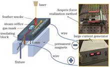
Objective Single-pass laser welding double-sided forming technology has the advantages of small welding deformation, high welding strength, large welding aspect ratio, and high welding efficiency. Under normal circumstances, the thickness limit of a sheet with double-sided welding in a single pass is 13 mm. When the sheet thickness reaches 15 mm or more, the biggest problem is to no longer optimize the process parameters to obtain a good weld seam; however, after the laser power exceeds the threshold and laser energy, steam, plasma, and other coupling behaviors in the keyhole are complex, the root molten pool drips and the weld is difficult to form. This paper proposes a method of using the upward Ampere force generated by a stable magnetic field and directional current to assist in improving the flow characteristics of the molten pool and suppressing the dripping of the root molten pool; improving stability of the welding process, quality of weld formation, and welding efficiency; and greatly improving the thickness limit of thick plates in single-pass laser welding.Methods The experimental material used in this study is 316L stainless steel, and the specifications of the specimens are 300 mm×40 mm×16 mm and 300 mm×40 mm×30 mm. The magnetic field is generated by a permanent magnet attached to the vise, and direct current is generated by a large current generator. In this experiment, 16-mm 316L stainless steel was first used to study the root dripping defects, and then 30-mm 316L stainless steel was used to investigate the ultimate thickness of laser single-pass penetration. In the study of 16-mm 316L stainless steel to suppress root dripping defects, four sets of comparative tests were first carried out: laser welding, laser current welding, laser magnetic field welding, and electromagnetic assisted laser welding. In order to ensure accuracy and credibility of the test and avoid the influence of current or magnetic field on the welding process, the single-factor experiment method is used to change only the magnetic field or current and keep other process parameters unchanged. The question is whether the Ampere force is the real force when electromagnetic-assisted laser welding of thick plates is studied, and the flow behavior of the molten pool at the root is photographed by a high-speed camera. In the study of the thickness limit of the 30-mm 316L stainless steel single-pass laser penetration process, the Ampere force was changed by variable current and constant other process parameters. The influence of the Ampere force on the depth of the 30-mm thick plate welding pool and weld formation quality impact was studied.Results and Discussions Among the results of the four sets of comparative tests (Fig. 3), only the test method of electromagnetic-assisted laser welding can achieve significantly better welding results than other sets of results. The weld seam is Y-shaped; weld formation and weld quality is good. Through the test results of electromagnetic-assisted laser welding of 16-mm 316L stainless steel plates (Fig. 4 and Fig. 5) and by adjusting the magnitude of the magnetic field or current, the weld morphology can be significantly changed. Therefore, in the experiments, it is the Ampere force rather than the current or magnetic field that inhibits the root molten pool dripping. With the presence of Ampere force, even if the dripping defect occurs, the root molten pool drips evenly and the root of the weld seam is flush, which can ensure formation of the weld without cutting. The high-speed camera shooting result (Fig.7) shows the flow behavior of the root molten pool during electromagnetic-assisted thick plate laser welding, indicating that the Ampere force cannot suppress root protrusion. However, the Ampere force suppresses dripping of the molten pool and the root molten pool protrusions after that. Under the combined action of the Ampere force and the surface tension of the molten pool, the molten pool flows back into the weld without other defects and a well-formed weld is obtained finally. Through the experiment results of electromagnetic-assisted laser welding of 30-mm 316L stainless steel plates (Fig. 6), it can be seen that the Ampere force affects the depth of the weld, but hardly affects the width of the weld. Only by selecting the appropriate Ampere force, the dropping in the molten pool can be suppressed thereby forming a good weld and ensuring that the material can be completely welded. By setting the appropriate process parameters, a single-pass laser welding can be achieved for a 30-mm stainless steel plate, which greatly improves the welding efficiency.Conclusions In this paper, electromagnetic-assisted laser welding of thick plates is used to carry out root molten pool dripping defect suppression process experiments and molten pool flow behavior research on 16-mm and 30-mm 316L stainless steel. In the experiments of 16-mm stainless steel to suppress the dripping defect of the root molten pool, neither the applied current nor the magnetic field alone can effectively suppress the root molten pool dripping defects generated during the single-pass laser welding of thick plates. Only by applying a constant electromagnetic field at the same time, the steady-state Ampere force generated can inhibit the dripping of the molten pool. During the welding process, the Ampere force can effectively inhibit the dripping of the molten pool, ensure good formation of the weld seam, ensure good welding quality, and improve the welding efficiency. In the 30-mm stainless steel laser single-pass penetration process test, the electromagnetic-assisted laser welding process method at constant current and constant magnetic field is feasible, laying the foundation for the development of ultra-thick plate laser welding process. During the welding process, the Ampere force can not only inhibit the dripping of the molten pool, but also significantly change the depth of the molten pool. The attached Ampere force cannot prevent the formation of root protrusions during the welding process; however, together with surface tension, it inhibits the downward dripping of the molten pool and helps the protrusion molten pool reflow to the weld area, ensuring effective weld formation.
May. 07, 2021Vol. 48 Issue 10 1002102 (2021)
Mingzhe Xi, Haoyang Zhou, Shuai Chen, Guangfa Cui, Kun Cheng, and Shengwei Zhang
Objective Traditional forging and machining technologies, which are used to produce titanium alloy parts, often involve long lead times and considerable material waste. It is much more effective to repair titanium alloy parts which are damaged due to wrong machining or are worn after long service than to simply discard them. As an advanced repair technology, laser repairing is often adopted to repair damaged titanium alloy parts. However, due to significant differences in microstructures and mechanical properties between the repair zone (RZ) and the titanium alloy parts, the mechanical properties of the titanium alloy parts that have been repaired by laser repairing are usually unwanted. This study proposes a novel type of repair technology that combines point-mode forging (PF) and laser repairing (LR) (called PF-LR) to repair TA15 titanium alloy forgings.Methods The PF-LR experiment was conducted using the in-house PF-LR system, which consists of a 3300 W fiber laser, a powder feeder, a coaxial powder delivery nozzle, and a four-axis computerized numerical control (CNC) PF-LR working table. The powder size of the TA15 titanium alloy is approximately 150 μm. The TA15 titanium alloy forging is 80 mm long, 20 mm wide, and 6 mm thick. An argon-purged chamber with oxygen content of less than 6×10 -6 was used to prevent oxidation of the molten pool. In the PF-LR process, first, a 0.5 mm thick layer of TA15 titanium alloy was deposited on the top surface of the forging. Next, the laser cladding layer of TA15 titanium alloy was forged point-by-point. Both LR and PF were performed alternatively until completion of the repair task. The LR and PF processing parameters are as follows: laser power (1500 W), spot size (3 mm), laser scanning speed (120 mm/min), LR overlapping ratio (30%), powder feed rate (8 g/min), reduction (0.2 mm), and PF overlapping ratio (20%). Results and Discussions The RZ of TA15 titanium alloy consists of equiaxed grains with an average size of approximately 200 μm. The microstructure of the RZ consists of basket-weave microstructure and transformed β. The microhardness of the wrought substrate zone (WSZ) is approximately 365 HV, which is lower than that of the RZ (405 HV). The microhardness in the heat affected zone rises sharply from the WSZ to the RZ, which means that the interface strength between the WSZ and the RZ is greater than that of the WSZ. Because of the smaller equiaxial grains and fine microstructures, the yield strength, tensile strength, and ductility of the RZ are 20.5%, 23.3%, and 93.7%, respectively greater than the minimum standard of aero-tensile mechanical properties of TA15 titanium alloy forging. The mechanical properties of TA15 titanium alloy forging, which contains 10% volume fraction of the RZ, are superior to the minimum standard of aero-tensile mechanical properties of forging. With the increase of the volume fraction of the RZ, the mechanical properties of forging repaired by the PF-LR technology increase gradually. Due to the coarse grain size and Widmanstatten structure, the tensile fracture mechanism of the WSZ exhibits a transgranular model with quasi-cleavage feature. The fracture morphologies of the forging containing 30% volume fraction of RZ showed a gradual transition model from the brittle fracture of the WSZ to the ductile fracture of the RZ.Conclusions PF-LR technology can be used effectively to repair damaged titanium alloy parts. This novel technology can produce a RZ of equiaxial grains in the forging of TA15 titanium alloy, whose grains are equiaxed. Because of the excellent mechanical properties of the RZ and the strong interface strength between the WSZ and RZ, all forgings with 10%, 30%, and 50% volume fraction of RZ reach and exceed the standard of aero-tensile mechanical properties of TA15 titanium alloy forging. This indicates that the PF-LR technology is completely appropriate for the repair of damaged TA15 titanium alloy forgings, which have flaws of different sizes.
Apr. 27, 2021Vol. 48 Issue 10 1002103 (2021)
Jinhua Li, Xuejia An, Fangping Yao, and Yan Hou
Objective Although metal surfaces can be effectively improved by laser cladding, the cladding process is affected by many factors. Thus, the research limited to a single experiment on this topic is inefficient and wastes resources. A combination of computer simulation and experimentation can greatly reduce the research period and improve the study efficiency. Numerous studies in computer simulation have provided a strong reference. However, the research on the thermal stress and thermal cycle in laser cladding is still rare. Here, a plane continuous heat source model and the COMSOL Multiphysics software are used to conduct a numerical simulation of the single-channel laser cladding process of H13 steels. The thermal stress and thermal cycle curves are drawn and analyzed to study the influence of the thermal stress cycle on the cladding layer under the optimal process parameters, and the laser cladding experiments are conducted to verify these simulation results.Methods Using a plane heat source, the numerical simulation on laser cladding of H13 steels with Ni-based alloy powder was conducted using COMSOL. The simulation data were determined according to the results from previous researches, and the simulation scheme of the thermal stress cycle including the melting temperature and the influence of the parameters was determined on the basis of the substrate and powder process. A curve was then drawn, and the results were analyzed. The proposed simulation scheme was selected for the laser cladding experiment to verify the accuracy of the simulation model, in which various dimensions of the cladding layer were measured. A horizontal screenshot of the cladding layer was then compared with the simulation results to verify the accuracy of the simulation model.Results and Discussions The optimal simulation scheme is determined and verified by experiments. According to the melting temperature requirements of the substrate and powder process and the influence of the parameters on the thermal stress, the laser power and scanning speed are set as 1200 W and 2 mm/s, respectively, for the simulation scheme of thermal stress cycle. The simulation scheme proposed here is selected for the laser cladding experiment to verify the accuracy of the simulation model. The cross-section of the cladding layer compared with the simulation results reveals essentially the same morphology, which verifies the accuracy of the simulation model. The thermal stress and thermal cycle are analyzed by drawing these parameter curves. The maximum temperature at various points in the vertical direction decreases with the increase of cladding depth. The top of the cladding layer shows the highest temperature of 2748.1 ℃, the heating rate of about 1632.1 ℃/s, the cooling rate of 699.5 ℃/s, and the matrix melting temperature of 1300 ℃. The maximum temperatures of sample points 6 and 7 are higher than the substrate melting temperature, and the highest temperature at sample point 8 is 1180 ℃ (Fig. 7). Therefore, the junction between the cladding layer and the substrate is located between sample points 7 and 8, which is consistent with the thermal cycle curve. The distance between the two sample points is 0.2 mm, and the depth of the molten pool is 0.2--0.4 mm. The shape of the molten pool can be determined according to the peak point of the thermal stress cycle curve. Sample points 8 and 9 in Fig. 8 do not show two obvious peaks. The lower side of the junction between the cladding layer and the matrix is located between sample points 7 and 8, which is consistent with the evaluation results of the thermal cycle curve (Fig. 8). In the von Mises thermal stress cycle, unstable alternating thermal stresses are identified at each sample point. All begin at 18.5 s and end at 20 s. Lots of unstable alternating thermal stresses at sample points 1--4 occur twice in concentration, with a steady increase in thermal stress occurring among them. The occurrence approaches each other gradually as the depth of cladding layer increases and joins together at sample point 5. As the depth of cladding layer increases, the variation amplitude of the alternating thermal stress first increases and then decreases, with the maximum stress amplitude of 45.5 MPa.Conclusions The optimal processing parameters are laser power and scanning speed of 1200 W and 2 mm/s, respectively. Laser cladding is conducted under the parameters such as the maximum temperature of about 2748.1 ℃, the depth of 0.28 mm for the molten pool, the maximum heating rate of 1632.1 ℃/s, and the maximum cooling rate of 699.5 ℃/s. The cross-section information of the molten pool is roughly consistent with the simulation result, which verifies the accuracy of the model. The laser power and scanning speed are proportional to the thermal stress at the sample point, and the thermal stress increases with the increase of laser power and scanning speed. Because laser cladding involves a solid-liquid transition, the thermal stress curves of most of the sample points show two peaks. When the sample is outside of the molten pool, the powder at the sample point does not melt, and the von Mises thermal stress curve of the sample does not show two obvious peaks. The duration of the unstable alternating thermal stress differs slightly at each sample point. With the increase of the cladding layer depth, the amplitude of the alternating thermal stress first increases and then decreases, and its duration increases continually. The unstable alternating thermal stresses at most sample points occur twice with the same beginning and end points that join together when the cladding layer reaches a certain depth.
May. 07, 2021Vol. 48 Issue 10 1002104 (2021)
Wenhao Sun, Yongqiang Fan, Guotao Zhang, Wu Tao, and Shanglu Yang
Objective Owing to the excellent strength-to-weight ratio, SiC particle reinforced aluminum composites have been widely used in the aerospace industry. To maintain the structural performance, the welded joint strength must be maintained. It has been a challenge for SiC particle reinforced aluminum composites to keep the weld strength as base materials due to the SiC particle dissolution and chemical reaction between SiC particles and base aluminum alloys during the welding process. In the past, the common approach to join SiC particle reinforced aluminum composites is arc welding or single laser beam welding or the corresponding parameters' optimization. There are limited studies on various laser-welding approaches on weldability of SiC particle reinforced aluminum composites, and their microstructure and mechanical properties. In this study, we selected three laser-welding processes to join SiC/Al composite, which include 1) hybrid laser-CMT welding; 2) single laser beam welding with filler wire; 3) dual laser beam welding with filler wire. We obtained that using the dual laser beam welding process can significantly improve the weld surface quality. Single laser beam welding with filler wire can produce the highest tensile shear strength of about 69.4% of base SiC particle reinforced aluminum composite strength. The tensile shear strength is only 62.5% and 53.8% of the base material for hybrid laser-CMT welding and dual laser beam welding with filler wire, respectively. The reason for the degradation of the weld strength is attributed to the formation of a large amount of porosity in the weld fusion zone.Methods Hybrid laser-CMT welding, single laser beam welding with filler wire, and dual laser beam welding with filler wire are used to join 4 mm SiC/Al composite with an ultimate strength of 318 MPa and volume fraction of 7.66% in a butt joint configuration. Tensile shear and micro-hardness tests are employed to evaluate the weld mechanical properties. The microstructures of the fractured weld are analyzed using scanning electron microscopy with energy dispersive X-ray spectroscopy (SEM/EDS). Besides, a digital microscope (KEYENCE: VHX-6000) is used to investigate the porosity distribution and ratio in various weld zones obtained using hybrid laser-CMT welding, single laser beam welding with filler wire, and dual laser beam welding with filler wire. X-ray powder diffraction (XRD) is used to identify the phase in the weld zone.Results and Discussions Hybrid laser-CMT welding and single laser beam welding processes produced a rough weld surface in 4 mm SiC particle reinforced aluminum alloy (SiCp/Al) composite. The weld surface quality is significantly improved (Fig. 3) using a dual laser beam welding process. The tensile shear test showed that the single laser beam welding process produced the highest weld strength, which reached 69.4% of the base material. The hybrid laser-CMT welding and dual laser beam welding processes produced the weld strength of 62.5% and 53.8% of the base material, respectively (Fig. 4). All welds failed in the mode of combining porosity with dimples (Fig. 6). The welds showed inhomogeneous hardness profiles with selected welding processes (Fig. 7) are due to variation in SiC particle distribution and porosity formation in the weld (Fig. 8). Using the XRD technique, we obtained that the SiC reinforcement particles chemically reacted with molten aluminum matrix, and the Al4C3 compound is produced in the fusion zone during the laser welding process (Fig. 10). The experimental results showed that under the selected welding parameters, the porosity is mainly concentrated on the top and bottom part of the fusion zone for hybrid laser-CMT welding (Fig. 11(a)). However, the center part of the fusion zone is occupied by a large amount of porosity for dual laser beam welding with filler wire (Fig.11(b)). Compared with hybrid laser-CMT welding and dual laser beam laser welding with filler wire, porosity is significantly reduced, and it is obtained through the entire weld depth (Fig.11(c)). To investigate the SiC particle sizes and their distribution after the laser welding process, it is essential to consider the image analysis approach to analyze the weld fusion zone. We obtained that the amount of SiC particle is reduced by dual laser beam welding with filler wire to the highest level among the three laser-welding processes (Fig. 13). This phenomenon could be explained due to higher heat input from the dual laser beam promoted the chemical reaction between SiC particle and molten aluminum matrix.Conclusions In this study, hybrid laser-CMT welding, single laser beam welding with filler wire, and dual beam laser welding with filler wire are selected to investigate the weldability of 4 mm SiC particle reinforced aluminum composite. The experimental results showed that uneven surfaces are usually found in the welds, which are achieved by hybrid laser-CMT welding and single laser beam welding with filler wire. The weld surface quality is significantly improved using the dual laser beam welding process. Under the selected welding parameters, the highest tensile shear strength of 208.2 MPa is obtained by single laser beam welding with filler wire, which is 69.4% of the base material. Besides, a large amount of porosity is found in the fusion zone, and their distribution is different. SiC reinforced particle is dissolved and segregated during laser welding process. The reduced SiC particle amount, porosity formation, and brittle Al4C3 formation in the fusion zone are the main reasons for the degradation of weld strength.
Apr. 27, 2021Vol. 48 Issue 10 1002105 (2021)
Taiqi Yan, Bingqing Chen, Pengjun Tang, Ruikun Chu, and Shaoqing Guo
Objective The rapid development of selective laser melting (SLM) technology provides an excellent solution for the rapid manufacturing of new complex aluminum alloy parts. Most studies on SLM of aluminum alloy remain in the stage of optimizing the processing parameters. Through continuous optimization of processing parameters, aluminum alloy samples with a density of over 99.00% and good tensile properties can be obtained. However, forming efficiency should also be considered in the actual forming process. To improve the forming efficiency, the most direct solution is to increase the layer thickness. The layer thickness determines the selection of other parameters, such as laser power, and the size of a single molten track and heat dissipation rate, which further determines the microstructure and properties of forming parts. Although properly increasing layer thickness is essential to improve the forming efficiency, if the layer thickness is excessively increased, the surface quality of formed parts will be severely reduced, and the metallurgical defects will also be increased, decreasing the mechanical properties. There are few reports on the effect of different layer thickness on microstructure, properties, and forming efficiency of SLM of aluminum alloy. In this study, the forming technology of AlSi10Mg alloy is investigated using optimized process parameters under different layer thickness. Besides, the influence of layer thickness on density, microstructure and properties, defects, and forming efficiency is analyzed, which provided a reference for further application of laser selective melted AlSi10Mg alloy in engineering.Methods AlSi10Mg powder with good appearance quality is selected. First, the aluminum alloy substrate is preheated to 150 ℃, and the oxygen content in the forming chamber is kept below 0.1%. Concept laser X Line 1000R is selected as a SLM equipment. The high layer thickness of 60 μm is compared with the low layer thickness of 30 μm. Other processing parameters are designed based on the layer thickness, and a series of square blocks and bars are formed. After forming, the samples are annealed at 260 ℃ for 2 h. The densities of the samples are measured using the Archimedes method. Then, the microstructure and internal defects of the samples are observed through the metallographic microscope and scanning electron microscope. The size of the samples’ defects is counted using Image-Pro Plus. The formed bars are used to test the room-temperature tensile properties. Finally, the fracture morphology is observed and analyzed using a scanning electron microscope.Results and Discussions The AlSi10Mg alloy with high density (Fig. 4 and Fig. 5) and good tensile properties (Fig. 6) can be formed under 30 μm lower layer thickness and 60 μm higher layer thickness. There are still differences as follows: the strength of AlSi10Mg alloy formed at 30 μm layer thickness is slightly higher than that of 60 μm layer thickness. This is attributed to the fine grain strengthening effect caused by smaller eutectic Si size in the 30 μm lower layer thickness samples (Fig. 9). Besides, the Z-direction elongation of the samples formed at 30 μm lower layer thickness is significantly higher than that at 60 μm higher layer thickness. This is because the molten pool at 30 μm lower layer thickness is smaller and densely arranged, leading to more zigzag crack propagation path and increased the difficulty of crack propagation; thus, resulting in a higher elongation (Fig. 7). The results showed that the defects with 30 μm lower layer thickness are more distributed in the molten pool boundary, while the defects with 60 μm higher layer thickness are more distributed in the molten pool. The Z-direction fracture surface with different layer thicknesses is perpendicular to each other (Fig. 10) since the eutectic Si in the boundary is relatively coarse, which becomes the weak area of crack propagation. When the AlSi10Mg alloy samples are with a density of over 99.00% and similar tensile properties, the forming efficiency with 60 μm higher layer thickness is about 2.7 times higher than that of 30 μm lower layer thickness.Conclusions The layer thickness effect on relative density, microstructure, tensile properties, and forming efficiency of AlSi10Mg alloy fabricated by SLM investigated. The results showed that within the optimized laser energy density range, the relative density of the samples fabricated at 30 μm lower layer thickness and 60 μm higher layer thickness reached over 99.00% and possessed good tensile properties. The tensile strength of the 30 μm lower layer thickness sample is slightly higher than that of the 60 μm higher layer thickness sample, which is attributed to the fine grain strengthening effect caused by the finer eutectic Si in the 30 μm lower layer thickness sample. The Z-direction elongation of the 30 μm lower layer thickness sample is significantly larger than that of the 60 μm higher layer thickness sample since it is not easy for cracks to propagate along the smaller and more densely arranged molten pool boundaries in the 30 μm lower layer thickness samples. The defects in the 30 μm lower layer thickness sample are distributed along the molten pool boundaries, while the defects in the 60 μm higher layer thickness samples are distributed inside the molten pool. Besides, the forming efficiency of 60 μm higher layer thickness is about 2.7 times higher than that of 30 μm lower layer thickness with similar forming quality.
Apr. 27, 2021Vol. 48 Issue 10 1002106 (2021)
Fan Gu, Qian Sun, Yuanxiang Huangfu, Jingyu Chen, Xiaonan Wang, and Lining Sun
Objective An intelligent material, NiTi shape memory alloy is widely used in mechatronics, aerospace, medical devices, and other fields due to its excellent properties, e.g., biocompatibility, corrosion resistance, shape memory effect, and super-elasticity. Successful adoption of NiTi depends on its intrinsic characteristics and applications bring about by connection with other materials. Copper has high thermal and electrical conductivity, ductility, and corrosion resistance, which plays an important role in electrical, pipeline engineering, aerospace, and other fields. Recently, the dissimilar joining of NiTi/Cu to electrothermal actuator has become a concern in this field because dissimilar joint of NiTi/Cu cannot satisfy shape memory effect requirements and ensure the high electrical conductivity of components. Laser welding is particularly suited to dissimilar NiTi joining compared with other connection modes; however, the weld mechanical properties decrease significantly compared to those of the base metal due to the brittle Ni-Ti intermetallics in the weld; thus, requirements can not be satisfied. To solve this problem, studies have investigated dissimilar welding of NiTi alloys by adjusting the welding parameters. In this study, we take NiTi alloy and copper wire as research targets and study the microstructure variation rules and the properties of NiTi/Cu laser-welded joints by changing laser offsets, which provides potential guidance for the application of the dissimilar welding of NiTi alloys and copper.Methods Laser welding of NiTi (Ni with an atomic number fraction of 50.2%) wire with 400-μm diameter and copper (Cu with an atomic number fraction of 99.9%) wire is performed using a pulsed laser. First, the wires are cleaned using acetone, ethanol, and deionized water to remove oil stains and contaminations prior to laser welding. Laser welding is conducted using a Miyachi Unitek LW50A pulsed Nd∶YAG laser (peak power is 0.9 kW, laser wavelength is 1.064 μm). During welding, pure argon is used as a shielding gas. Various laser offsets are obtained using different laser beam positions: 100 μm on NiTi side, 50 μm on NiTi side, centerline, 50 μm on copper side, and 100 μm on copper side (Fig.1). Cross sections of the welded joints are mounted in epoxy and grinded with sandpaper (up to number 1200) and then polished successively to 2.5, 1.0, and 0.5 μm using diamond sprays. This is followed by etching with Kroll reagent for 1 min. The microstructures are observed using an Olympus BX51M optical microscope and a Zeiss Ultra Plus field emission scanning electron microscope equipped with EDX to analyze the compositions. A Clemex CMT automated micro-Vickers hardness tester is used to make a series of 50-g indents across the fusion zone, 50 μm apart with a dwelling time of 10 s. The joints are using an Instron 5548 micro tester at a strain rate of 3×10 -4 s -1. Results and Discussions Laser offset is found to play a significant role in the microstructure due to the difference in mixing patterns and composition distributions. The results demonstrate that weld width decreased when moving the laser position from NiTi to Cu (Fig. 5), and the uniform distribution of the mixing pattern inside the weld zone changes to the local segregation [Figs. 7(a)--7(d)]. Welds with offsetting of 50 μm on the NiTi and centerline exhibited dendritic solidification microstructures, and welds with offsetting of 50 and 100 μm on Cu comprise a mixture of dendritic, cellular, and lamellar microstructures (Fig. 6). The hardness of the weld seam is reduced by with shifting the laser position from the NiTi side to the Cu side. When the laser offset is on the Cu side, local high hardness values appeare in the NiTi-rich region [Figs. 7(e)--7(h)]. The 100-μm Cu offset joint fracture in the weld zone during tensile loading due to the cracks insight, and the strength decreased significantly compared to the Cu base metal (Fig.8).Conclusions The results demonstrate that the proportion of NiTi alloys in the molten pool decreases gradually, and the decrement of NiTi alloys is greater than the increment of Cu when moving the laser position from NiTi to Cu, which results in reduced weld width. When the laser offset is on the Cu side, the increase of copper makes the weld zone have a very fast cooling rate and solidify quickly, which leads to the liquid copper and liquid NiTi in the molten pool not being fully mixed and forming element segregation. The welds with the offsetting of 50 μm on the NiTi and centerline exhibit homogeneous dendritic solidification microstructures that are also NixTiyCuz intermetallics. Welds with offsetting of 50 and 100 μm on Cu comprise a mixture of dendritic, cellular, and lamellar microstructures composed of NiTi intermetallics, CuTi intermetallics, NixTiyCuz intermetallics, and a copper solid solution. The hardness of the weld seam decreases by shifting the laser position from the NiTi side to the Cu side. When the laser offset is 50 μm on the NiTi side and the centerline, the hardness distribution in the weld zone is uniform, and average hardness is approximately 520 and 340 HV, respectively. When the laser offset is on Cu side, the hardness in the weld is very uneven, and local high hardness values appear in the NiTi-rich region. By changing the laser offset from 50 μm on the NiTi side to 50 μm on the Cu side, the NiTi/Cu dissimilar welded joint strength is close to that of the copper base metal, which is primarily due to preferential failure of the softer copper base metal in tension. The 100-μm Cu offset joint fractures in the weld zone during tensile loading due to the cracks insight, and the strength decreases significantly compared to Cu base metal.
May. 07, 2021Vol. 48 Issue 10 1002107 (2021)
Jieyan Gu, Chongjing Yan, Chichao Zhang, and Zikang Shen
Objective Precision achievable by laser bending is a critical factor affecting its practical application. It is difficult to control the accuracy of the bending angle at a high level due to the influence of factors, such as the geometric size and initial state of a sheet and the process parameters, even for linear scanning of a single scanning path. To achieve high-precision single-curved laser bending, not only the error of the bending angle at the single scanning path should be considered but also other factors that will affect the accuracy of bending, so as to devise a strategy to improve bending accuracy. In this research, we improve the scanning path planning method and propose a method to compensate for the error of the laser-bending angle. Each time the bend at a scanning path is completed, the bending angle at the next scanning path is redetermined to compensate for the bending angle error in the previous scanning path. This method allows a large tolerance for the bending angle at each scanning path, which reduces the process requirements. The proposed method will help realize the high-precision of 3D laser bending and the further practical application of laser bending.Methods First, using the improved Denavit-Hatenberg (D-H) modeling method in robotics, the coordinate system of each bending section of a sheet is established, and the mathematical description of the curved sheet and target single surface in the same coordinate system is obtained by coordinate transformation. Therefore, the problem of sheet bending error is transformed into a problem of deviation of the segment to be bent from the target surface. Then, based on the D-H modeling method, the geometric influence factors of the bending angle tolerance at different scanning paths of cylindrical surface forming as well as the degree to which these factors affect the forming accuracy are analyzed. Afterward, based on the fact that a bending section completed first will not affect the forming error of a bending section completed later, a compensation method for the bending angle error at each scanning path is proposed. The deviation of the bending section from the scanning path is compared for two cases (using and not using the compensation method during forming) by forming simulation. Finally, an experiment is designed to verify the error compensation method; the improved D-H modeling method is also used to measure the bending angle in the experiment. During the experiment, the influence of factors, such as the initial state of a sheet and the perpendicularity between the sheet and laser displacement sensor, on the measurement results are considered. The heating conditions are obtained through laser-bending experiments on small-sized sheets.Results and Discussions The tolerance design for cylindrical surface forming shows that the number of scanning paths have the greatest influence on the bending angle tolerance at a single scanning path (Fig. 4). Compared with a method with one-sided initial profile deviation, the proposed path planning method with two-sided initial profile deviation can reduce the number of scanning paths under the same maximum profile deviation or scanning paths (Fig. 6). The proposed method can effectively reduce the deviation of the curved section from the planned path. Without error compensation, the deviation is much greater under the same bending angle error, compared with using error compensation (Fig. 9). A half-sine surface forming experiment is designed to verify the error compensation method. The formed half-sine surface has high accuracy, and the overall profile deviation is about -0.15--0.25 mm (Figure 14).Conclusions The improved D-H modeling method can be conveniently used for tolerance analysis, error compensation, and bending angle measurement of single-curved surface laser bending. Through the tolerance design of the bending angle of the laser bending forming of a cylindrical surface, it is found that the number of scanning paths has the most significant influence on the bending angle tolerance at each scanning path. Particularly, the number of scanning paths affects the overall size of the bending angle tolerance; the more the number of scanning paths, the narrower the bending angle tolerance band at each scanning path. The proposed path planning method with two-sided initial profile deviation can reduce the initial profile deviation of path planning. The proposed error compensation method improves the accuracy of the single-curved laser bending. It has a low tolerance requirements for the bending angle of a single scanning path and allows the two-sided error of the curved section to the target surface. The forming experiment of a half-sine surface is designed to verify the error compensation method. The formed parts have high accuracy, which show that the proposed error compensation method is effective.
May. 19, 2021Vol. 48 Issue 10 1002108 (2021)
Zhengwei Chen, Chang Li, Xing Gao, Hexin Gao, and Xing Han
Objective Laser quenching has the advantages of small thermal deformation and thermal stress, short process cycle, stable and controllable quality, and high treatment efficiency. It can effectively improve the surface wear resistance, corrosion resistance, and fatigue resistance of mechanical parts. Recently, laser quenching has been widely used in many fields, such as automotive, aerospace, and mold. The macroscopic properties of a matrix material are the statistical results of all microscopic grains, and the mechanical properties are determined by the final state of all microscopic grains. The key to achieving precise control of the mechanical properties of the matrix is to optimize the microstructure during laser quenching. Therefore, to reveal the microevolution mechanism of the matrix in the laser quenching process is of great significance for optimizing the microstructural characteristics in the process. Laser quenching is a complex multi-field coupling process, and the microstructure changes instantaneously during the laser quenching process. It will consume a considerable amount of efforts to determine the laser quenching microevolution mechanism through repeatable experiments and traditional numerical simulation methods. In this study, a laser quenching model considering grain heterogeneity was developed on the ABAQUS platform with the Python script. This approach provided an effective method to reveal the laser quenching mechanism at the microcrystalline scale.Methods First, a random microcrystalline structure model for the matrix was established by the Voronoi tessellation method. Then, the unquenched matrix nano-indentation test was conducted with a Keysight Nano Indenter G200 nano-indentation tester. The test results showed that the grains in the unquenched matrix were inhomogeneous (Fig. 3). The grain non-uniformity coefficient was calculated from the nano-indentation measurement results according to Eq. (8) and analyzed using statistical methods. The analysis results showed that the grain non-uniform coefficient obeys a normal distribution [Fig. 4(a)]. According to the grain non-uniformity coefficient, the grains in the unquenched matrix can be divided into seven types. After considering the sample points and the experimental errors, the grain non-uniformity coefficient distribution was standardized [Fig. 4(b)]. The mechanical properties of each type of grain were calculated according to the grain non-uniformity coefficient [Eq. (9)]. Finally, a Python script was used to randomly assign various material attributes to Voronoi cells in the unquenched matrix according to the grain non-uniformity coefficient after treatment (Fig. 5). A thermo-mechanical coupling model for the laser quenching process of SUS301L-HT stainless steels was established. The temperature field and thermal stress field were calculated.Results and Discussions During the laser quenching process, the matrix rapidly produces temperatures and thermal stresses under the action of a high-energy laser. The temperature field of the matrix diffuses from the spot center to the surrounding. The matrix is simultaneously subjected to the combined effects of heat radiation, heat convection, and heat conduction during the transfer process. Thus, the matrix temperature decreases gradually from the heat source center to the outside. The temperature field distribution is approximately symmetrical, with the scanning track as the axis. The back of the heat source continuously inputted quantities of heat by heat conduction. Thus, the temperature gradient in the front of the heat source is larger than that at the back. After natural cooling for 300 s, the temperature of the matrix is close to room temperature. The change in the temperature field of laser quenching showed that the characteristics of rapid cooling of laser quenching are prominent (Fig. 7). The characteristics of the temperature field distribution of laser quenching are consistent with the experimental results (Fig. 8). The distribution of the thermal stress field in the matrix is similar to that of the temperature field. Due to the high temperature in the heat source center, the metal mechanical properties in the region are reduced. Thus, the value of the thermal stresses in the center of the heat source is relatively small. The thermal stress of each crystal grain in the matrix is different, and the thermal stress of adjacent grains in the matrix occurs a sudden change at the grain boundary. Therefore, the thermal stress of the entire matrix presents a non-uniform distribution similar to the random geometric structure of the grain boundary. A few grains in the matrix have high mechanical properties. Under the laser irradiation, the thermal stress of these grains is higher than the average level, reaching 1429 MPa. However, the stress level of most grains in the matrix is about 600 MPa. Therefore, it can be found that the part of the grains with a higher thermal stress only represents the thermal stress state of the grains themselves, and it has a little contribution to the thermal stress state of the entire matrix (Figs. 9 and 11).Conclusions Because of the inhomogeneity of the grain mechanical properties in the matrix, a sudden change in the grain stresses occurs at the grain boundaries. The larger the difference in the mechanical properties between adjacent grains is, the more obvious the stress mutation at the grain boundaries is. The thermal stress isolines show a similar irregular distribution with the grain boundary random geometry for the entire matrix. The laser quenching model considering the grain inhomogeneity can effectively capture the temperature and thermal stress changes of each grain in the matrix during the quenching process.
May. 07, 2021Vol. 48 Issue 10 1002109 (2021)
Xianglong An, Yuling Wang, Fulin Jiang, Jie Zhang, and Jinying Zhang
Objective Laser cladding involves rapid heating and quenching processes. During rapid cooling, the temperature field distribution is uneven because the molten pool temperature suddenly drops, generating residual stress. Residual stress in the cladding layer directly affects the mechanical and physical properties of the cladding layer, leading to cracks and other defects. To reduce the manufacturing costs, the residual stress in the cladding layer is usually calculated in numerical simulations. However, most of the simulation studies focus on single-pass cladding; the influence of lap ratio on the residual stress under multipass cladding has been little investigated, and the relationship between lap ratio and residual stress has not been concluded. In actual production, multipass cladding is the norm, and the subsequent cladding-layer processing is also based on multipass overlapping cladding layers. To reduce the machining allowance and improve the cladding-layer quality in multipass cladding, we studied the factors influencing the residual stress in the cladding layer and the laws governing those influences in finite element simulations. After determining the residual stress distribution in the cladding layer for different lap ratios, the most suitable lap ratio for subsequent processing was determined.Methods The matrix is 42CrMo steel and the powder is 3540Fe. Multipass cladding models with constant thickness (1 mm) and varying lap ratio (30%, 40%, 50%, 60%, and 70%) were established in Ansys software. The temperature-rise model of the laser cladding was based on the model of laser-melting temperature rise and powder absorptivity. The accuracy of the analytical model is verified by comparing with the simulated temperature model. The residual stress distributions in the cladding layers with different lap ratios were obtained by simulating the thermal-mechanical coupling in finite element software. The physical properties of the cladding layers were observed in corresponding experiments. The experiments confirmed the macro- and micro-morphologies of the cladding layers with different lap ratios and the physical properties of the cladding layers prepared at different lap rates. Finally, the most suitable lapping ratio of the cladding layer for subsequent processing was obtained.Results and Discussions As demonstrated in the finite element simulation results (Fig. 4), the temperature of the cladding layer gradually increased with lap ratio increasing. The residual stress distributions in cladding layers with different lap ratios are displayed in Fig. 6. Increasing the lap ratio gradually decreased the residual stress in the cladding layer. In the experiments, increasing the lap ratio obviously refined the grain size of the cladding layer (Fig. 8). At lap ratios below 50%, the cladding layer was strongly bonded with the substrate, but at lap ratios exceeding 50%, the cladding layer presented obvious defects. Increasing the lap ratio gradually increased the microhardness of the cladding layer (Fig. 9), but nonlinearly affected the friction coefficient of the cladding layer (in particular, the friction coefficient decreased before increasing; see Fig. 10).Conclusions The following conclusions were drawn from the study. Increasing the lap ratio gradually increased the temperature of the cladding layer, mainly because the substrate temperature was increased prior to the next cladding. This phenomenon is equivalent to preheating the cladding layer. Therefore, the temperature of the cladding layer (including its maximum) gradually increased with number of passes. Increasing the lap ratio also gradually reduced the minimum residual stress in the cladding layer, which appeared at approximately 0.2 mm below the top of the cladding layer. The residual stress in the cladding layer became gradually uniform, and the position of maximum residual stress gradually approached the direction of the matrix. As the lap ratio and temperature increased, the elements in the matrix floated toward the cladding layer and formed a hard phase in that layer. Accordingly, the cladding layer demonstrated a gradually increasing microhardness, and a friction coefficient that first increased and then decreased. Among the cladding layers manufactured at different lap rates, the cladding layer formed at the 50% lap rate was well bonded with the substrate, and demonstrated an obvious antiwear effect, moderate average residual stress, and relatively high cladding efficiency. Therefore, this sample was deemed most suitable for subsequent processing.
Apr. 27, 2021Vol. 48 Issue 10 1002110 (2021)
Yazhou Mao, Jianxi Yang, and Wenjing Xu
Objective Because of the high pollution, low efficiency, and long processing cycle in the chemical etching of surface texturing, the surface texturing of brass material was processed by laser-machining technology. Laser surface texturing process and its mechanism for brass material under the action of long-pulse laser (LPL) were investigated, which helped in the processing of brass material surface texturing by LPL in practical engineering applications.Methods A thermal model for surface texturing was established based on Neumann boundary conditions. The reflectivity, refractive index, and extinction coefficient of material surface under the action of LPL and the absorptivity of materials under different temperatures and wavelengths, surface vapor pressure, liquid mass mobility, and forming efficiency were analyzed. The effects of different parameters on thermal model, thermal stress, and damage threshold during LPL surface texturing were investigated, and the surface texturing formation mechanism was obtained using scanning electron microscopy (SEM) and energy dispersive spectroscopy (EDS) to analyze surface texture.Results and Discussions The results show that to ensure lower reflectivity R (e.g., K in [0, 0.019] and refractive index n in the range of 1nAaluminum>Agold>Acopper>Asilver>Azinc) (Figs. 2 and 3). In addition, the temperature distribution during the LPL surface texturing process of brass material shows a symmetrical distribution in the shape of a “hat,” and the temperature at the center point (r=0 mm, z=0 mm) is the highest (Fig. 5). With the increase in laser radius and axial distance, the temperature gradually decreases, and the temperature of the heat conduction decreases with the increase of depth (Fig. 6). The narrower the pulse width, the stronger the vapor pressure and the more liquid mass mobility (Figs. 7 and 8); however, micropit-forming efficiency experienced three stages: stable (currently, LPL energy EE≤6 J, the material removal strategy is the combined effect of evaporation and splashing, and the micropit-forming efficiency is the highest when LPL energy E=6 J) and gradually decreases (currently, LPL energy E>6 J; the evaporation rate of material removal is almost the same as the liquid mass mobility. Once the material's evaporation rate is higher than the liquid mass mobility, the forming efficiency of micropits stops changing) (Fig. 9). Further research shows that compressive stress is an essential mechanism for the damage effect. The damage of brass is concentrated on the laser light spot, and circumferential thermal stress is the main factor causing damage of brass material (Fig. 10). The maximum radial circumferential compressive stress occurs at the laser light spot, and the material damage because of high power density and narrow pulse width is severe, whereas the axial circumferential compressive stress gradually decreases with the increase of depth and pulse width (Figs. 11 and 12). Thermal stress (compressive stress) damage of the material surface occurs before the melting damage, and the circumferential thermal stress is the main factor of diameter expansion (Fig. 13). However, as time passes, the damage of brass material is mainly caused by melting damage, and the melting damage is responsible for melting radial material (Fig. 15). In the process of laser surface texturing, along with the occurrence of hardening phenomenon(Fig. 16), the energy also presented a gradually decreasing trend from region 1# to region 3# in EDS analysis (Fig. 18). In addition, CuO and ZnO are generated (Fig.19) during the process of laser surface texturing.Conclusions Laser machining is an effective method for the surface texturing of brass material. There are five stages in the formation process of laser surface texturing of brass material: ablation, melting, splashing, cooling, and forming. The local quenching area of micropit surface texturing formed by laser machining can promote the formation of martensite structure, which will eventually cause the brass surface to harden in the heat-affected zone, and the surface hardness is increased by 50%.
Apr. 29, 2021Vol. 48 Issue 10 1002111 (2021)
jin Wang, Rudong Zhou, Ning Zhang, Junfeng Cheng, Zheng Cao, Qiang Wang, Dun Wu, and Chunlin Liu
Objective In recent years, graphene-based nanomaterials have been widely studied because of their excellent chemical and physical properties. Among other applications, graphene has been successfully used in sensors and catalysis. Graphene can form a three-dimensional porous structure with a high surface area, depending on the method of synthesis. The assembly of graphene oxide (GO) into foam is one of the conventional methods employed to fabricate porous graphene structures. However, this approach needs the preparation of GO precursor via oxidative-acid synthesis route. Porous graphene can be processed via chemical vapor deposition on porous substrates, but high temperature and complex post-processing activities limit its commercialization. Recently, a facile approach to the formation and patterning of porous graphene on polyimide (PI) under ambient conditions using commercial laser scriber was reported. This one-step process of making laser-induced graphene is better than conventional methods for synthesizing porous graphene, and the method is also relatively simple and cheaper. Presently, there are few domestic studies on laser direct writing PI. In this present study, we report the effects of three sets of laser-process parameters on the carbon forming performance of 1064 nm laser direct writing PI films. We expect our methods and findings to provide a reference for the process parameters of carbon forming of PI film written by 1064 nm laser.Methods Commercial polyimide films were employed in experimental research. First, the 1064 nm fiber laser was used to directly write on the PI film, while the PI film carbonized after absorbing the laser energy. A scanning electron microscope, Raman spectrometer and X-ray photoelectron spectrometer were used to analyze the morphology and chemical composition of laser direct writing PI film. The four-probe and the contact angle measuring instruments were used to measure the conductivity and hydrophilicity of the laser direct writing PI film. The effects of three groups of parameters (spot size and line spacing; scanning speed and pulse frequency; laser power) on the carbon formation of PI film by laser direct writing were studied.Results and Discussions The Raman spectrum shows that the laser direct writing PI film has three characteristic peaks of carbon: D peak at 1344 cm -1, G peak near 1500 cm -1, 2D peak at 2683 cm -1 (Fig.3). The XPS results of the material show that there are C1s, O1s, and N1s peaks. Carbon atoms exist in four forms (C—C, C—O—C, C—N, and C=O), and the C—C bond is the main component of carbon (Fig.4). The spot size, line spacing, scanning speed, and pulse frequency affect the conductivity of the laser direct writing PI film to certain degrees. When the laser power is low (1.8--2.0 W), the laser leaves some flocculation on the surface of the PI film. With an increase in laser power, holes gradually appear on the PI film, leading to the formation of a three-dimensional porous structure (Fig.7). The contact angle of the laser direct writing PI film is positively correlated with the degree of damage of the PI film surface. By calculating the ID/IG and I2D/IG, it can be deduced that there is an initial decrease in the defect degree of the carbon layer, followed by an increase as the laser power increases (Fig.8). Conclusions In this study, using 1064 nm fiber laser direct writing PI film, the influence of laser-process parameters on PI film was studied. The PI film absorbs the pulse laser energy and performs a photothermal conversion, and finally forms a three-dimensional porous carbon layer. In the molecular chain of PI, chemical bonds such as C—H, C=O, C—N, etc. are broken and rearranged. The mass fractions of C, N, and O elements in the laser direct writing PI film are 84.84%, 2.02% and 13.14%, respectively. Using different laser processing-technology and parameters, the conductivity of the carbon layer formed by laser direct writing PI film is studied. The best combination of parameters for the conductivity of laser direct writing PI film was obtained: the laser line spacing was 0.001 mm, the spot size was 0.06 mm, the scanning speed was 150 mm/s and the pulse frequency was 40 kHz. With an increase in laser power, the degree of microscopic ablation morphology of the laser direct writing PI film gradually increases, and the surface changes from a small flocculent carbon particle to a three-dimensional porous carbon structure. With a laser power of 2.2 W, the carbon flaw is the lowest and the carbon crystallization rate is the highest. At this laser power, the sheet resistance is also the lowest (55 Ω/sq). In addition, the contact angle of the laser direct writing PI film increases with a gradual increase in laser power. The surface of the laser direct writing PI film shows superhydrophobicity while the laser power is 2.8 W.
May. 19, 2021Vol. 48 Issue 10 1002112 (2021)
Lanyun Qin, Yongkai Xie, Guang Yang, Wei Wang, and Xiangming Wang
Objective With the rapid development of science and technology, there is increasing demand for high-precision workpieces in various fields, especially in space shuttles, aero-engines, space station, and medical fields. As one of the important branches of additive manufacturing, laser deposition-manufacturing technology plays an important role in high-precision and high-intensity manufacturing. In the laser deposition-manufacturing process, owing to the effects of some factors, such as heat accumulation, inevitably produces edge collapse, and the surface concave and convex inequality forming size deviation value phenomenon, resulting in a large deviation between the actual morphology and the ideal morphology. It affects the forming accuracy of the workpiece, and after multiple stacking manufacturing, the more concave the concave, the more convex the convex, which hinders the further progress of deposition manufacturing. Currently, research institutions and universities globally mainly focus on the optimization of forming processes, analyses of the structures and performance of the formed parts, and stress distribution during the forming process. There are only a few studies on improving the forming accuracy, such as morphology deviation and control. Meanwhile, it is vital to detect and control morphology deviations in sedimentary layers during forming processes.Methods In this study, a high-speed profilometer was used to set up a sedimentary profile detection system, which was integrated into laser deposition-manufacturing equipment to detect and control sedimentary profile deviations. First, the high-speed profilometer was used to scan the surface of the sedimentary body, and the obtained three-dimensional morphology point cloud data were compared with the theoretical data of the sedimentary layer slices to extract the point cloud data that form the deviation area. Then, the deviated-area point cloud was layered and sliced, and the slices were converted to binary images by organizing the point cloud. The image boundary pixel points were extracted with the image boundary recognition algorithm and converted to coordinate points (i.e., the deviation contour point of the slice). The deviation contour feature line was fitted with the cubic B-spline curve. Finally, the accurate position of the deviated contour area in the original section contour area was determined, the filling space within the deviated contour area was changed, the forming track was filled, the deposition program was generated, and the deviated area was compensated. The flatness error on the surface of the sedimentary body before and after compensation was calculated, and the variation of the surface morphology deviation was analyzed.Results and Discussions The results show that the morphology detection system can quickly obtain the morphology point cloud data of sedimentary bodies (Fig. 6). After the point cloud was denoised, a relatively ideal point cloud was obtained (Fig. 7). A pair of parallel planes was used to contain the denoised point cloud data to form the minimum containment area, and the flatness error value of the sample was obtained (Fig. 8). The morphologic point clouds are compared with the theoretical data of standard sediment slices to extract the deviated area point clouds (Fig. 9). The point cloud of the deviated region was layered and sliced, and the slices were converted into binary images. Then the deviated contour points of the slices were extracted and fitted using the image boundary recognition algorithm (Fig. 10). Finally, we propose a compensation path planning method based on changing the filling space of the deviated area to generate a compensation path, and the degree of depositional morphology deviation after compensation processing was significantly reduced compared with that before compensation (Fig. 11).Conclusions Based on the above results, we draw the following conclusions. The laser deposition-manufacturing morphology detection system established can quickly scan the surface of the deposition to obtain the morphology point cloud data and the contour of the deviated region by processing the point cloud data. The accurate position of the deviated contour area in the original section contour area can be determined. Since the sedimentary shape is a sag deviation, the filling trajectory of the deviated contour area is filled and the compensation path is generated by reducing the filling space of the deviated contour area. The experimental results show that the deviation of the morphology of the sediment was compensated. The surface flatness error of the sample before and after compensation was 1.95 mm and 0.68 mm, respectively. This represents a 65.1% decrease in the fatness error. The degree of morphology deviation of the sample was significantly reduced, ensuring continuous deposition manufacturing and small machining allowance in the subsequent material reduction processes.
May. 19, 2021Vol. 48 Issue 10 1002113 (2021)
Mingyu Wang, Shihong Shi, Tuo Shi, Geyan Fu, Yifan Pang, Siqi Yu, and Yanqi Gong
Objective In the fields of aerospace, machinery, ships, etc., there are many multivariant twisted structures, such as fan blades in turbofan engine intakes, ternary blades in centrifugal compressors, and ship propellers. These parts have common structural features including large inclination and twisting, which cause great difficulties in processing. Currently, multivariant twisted structural parts are mainly based on computer numerical control milling, casting, electrochemical machining, etc. However, these machining methods have their own problems, such as low material utilization and long production cycles, and in some cases, it is difficult to meet performance requirements. Laser-cladding forming technology is a new type of rapid prototyping technology for metal parts that was proposed in the 1990s. It can be used for rapid and mold-free manufacturing of high-performance and complex parts. Therefore, research on laser-cladding forming of multivariant twisted structures has broad applications. At present, the laser-cladding forming of multivariant twisted structures at home and abroad is mostly based on uniform cross-section and single-direction twisting, while there are few reports on the structural parts that are twisted in multiple directions in space, especially the formation of the gradual cross-section in this type of structural parts. Based on the self-developed optical internal powder feeding technology, this paper adopts the method of conformal discrete layering to obtain the movement trajectory of the laser-cladding nozzle, and realizes the accumulation and forming of the multivariant twisted structure.Methods The multivariant twisted structure described in this paper presents a three-dimensional twisted shape in space, with complex twisting and tilting characteristics. To realize the laser-cladding forming of the twisted structural part, based on the principle of normal delamination, this paper proposes a method of discrete layering following the shape to layer the multivariant twisted structural part. First, the structure is divided according to the shape characteristics of the structural part. The structure are divided into different parts for layering and the center line of each part is extracted; then, normal slices are made along the center line of each part. Finally, according to the characteristics of each slice layer, the slices are discretized twice to produce a different discrete cladding unit with geometric characteristics. The movement trajectory of the light spot is determined by the position and direction information of each part of the discrete unit. The cladding nozzle moves according to the position and direction information in the discrete unit to accumulate and form the multivariant twisted structure.Results and Discussions The conformal discrete layering method is proposed to layer the multivariant twisted structure to obtain discrete cladding units with different geometric characteristics [Fig. 3(d)]. The trajectory of the light spot is determined by the position and direction information of each part of the discrete unit. The formation of the cladding layer can be regarded as the translation and rotation of the tool coordinate system, where the light spot is located relative to the base coordinate system in which the substrate is located [Fig. 4(a)]. Through translation and rotation operations, the homogeneous transformation matrix of each discrete unit relative to the base coordinate system is obtained, and the changes in position and direction change of each discrete unit relative to the base coordinate system are obtained, thereby yielding the laser-cladding nozzle's movement track. This study uses the method of robot trajectory approximation, where, through the control of program commands, the robot does not stop at the dislocation position, and realizes the gradual cladding formation of the multivariant twisted structure [Fig. 4(b)]. The experiment uses a self-developed inside-laser powder-feed nozzle, which has good powder-beam bundling, and realizes the laser-cladding forming of multivariant twisted structural parts (Fig. 7).Conclusions To obtain the forming trajectory of multivariant twisted structural parts, a method of discrete layering according to shape is proposed: a normal discrete slice of the entire structural part is made, and then each layer of the slices is discretized twice to obtain a discrete cladding unit with different geometric characteristics. The conformal discrete layering method is used to solve the layering problem of the gradual structure of the cross section in the multivariant twisted structure, obtain the spatial movement track information of the laser-cladding nozzle, and complete the accumulation of the multivariant twisted structure. The inspection results of the formed parts are as follows: the surface of the formed parts is smooth with a surface roughness value within 5.579 μm; the average thickness of the formed parts is 6.03 mm, and the thickness of each part is slightly increased; the forming accuracy of the formed parts is higher, with a shape and size error from -3.45%--3.09%; the hardness of the different formed parts differed slightly but were basically stable at 271.6--284.5 HV; there is no obvious difference in the overall structure of the formed part; and the structure of each part is dense and uniform, without obvious pores or cracks.
May. 19, 2021Vol. 48 Issue 10 1002114 (2021)
Guang Yang, Yuhang Li, Siyu Zhou, Xia Wang, Lanyun Qin, and Xiangming Wang
Objective Large-scale integral titanium alloy structural parts have been used as an indicator to measure the technological advancement of defense equipment. Laser additive manufacturing technology, with its unique advantages, has gradually become one of the processing methods for large-scale integral titanium alloys. In laser additive manufacturing, formed parts are circularly heated by a focused and high-energy laser beam. A large temperature gradient will be established in the formed parts, resulting in complex stress and strain evolution during the forming process. After forming, enormous residual stress is generated inside the formed elements, causing the substrate to warp significantly. This problem has been one of the factors impeding the development of this technology. Many scholars have found that the method of subfield scanning can effectively control the internal stress during additive manufacturing of large-scale components. However, the layer configuration of the large frame structure is relatively complicated. It is necessary to consider the appropriate means for planning the scanning trajectory and jump sequence according to the structural characteristics of large-scale frame structures.Methods To mitigate the deformation and cracking of formed parts in laser additive manufacturing due to uneven temperature distribution, a subfield scanning strategy based on characteristic regions was proposed. This study focused on two aspects: scanning starting point positions and jump strategy between characteristic regions. First, ANSYS was used to simulate two kinds of characteristic regions' deposition manufacturing processes, including the L-shaped and T-shaped regions. The influences of the ipsilateral side starting point scanning and the opposite side starting point scanning on the temperature field distribution of characteristic regions and the thermal cycle of substrates' nodes were analyzed. The best scanning starting points for the two characteristic regions were identified. After that, the frame structures' deposition manufacturing processes were simulated using three jump scanning strategies: continuous jump, interval jump, and maximum span jump. The temperature distribution nephograms of the frame structures under the three jump scanning strategies were obtained. Second, temperature field simulation results were loaded on stress analysis models to analyze the stress evolution process. Finally, the thermocouple's temperature variations of substrates' nodes during the deposition processes were monitored, and substrate deformation after deposition was measured. The experimental and simulation results were analyzed.Results and Discussions The above research shows that changing the scanning start points will affect the L-shaped and T-shaped characteristic regions' temperature distribution. When using opposite side starting points to deposit characteristic regions, the influence range of temperature can be reduced; the cumulative heat effect can be reduced (Fig. 3), thereby decreasing thermal behavior's influence during the deposition process on the substrate's mechanical properties. In addition, when using opposite side starting points to deposit characteristic regions, the substrate's nodal thermal cycle curve rises slowly, and the node's peak temperature is also low (Fig. 4). When the frame structure's deposition is only completed, the maximum temperature of the molten pool with the maximum span jump scanning is lower than the interval jump scanning and continuous jump scanning (Fig. 7). During the deposition process, the three jump strategies' stresses are distributed in the characteristic region, where the scan starts, and the characteristic regions' junctions. The phenomenon of stress concentration becomes more visible as the deposition layer's height increases (Fig. 8). The deposited layer's stress distribution range does not change much after cooling; the substrate's high-stress area gathers to the constrained position, concentrated on both sides of the constrained end. The stress at maximum span jump scanning is lower than that at interval jump scanning and continuous jump scanning (Fig. 9).Conclusions Following the above analysis, this article proposed a subfield scanning strategy based on characteristic regions for the large frame structure, classified according to its organizational characteristics. It is divided into two characteristic regions: T-shaped and L-shaped regions. The effects of scanning start point positions and character regions' jump scanning strategy on thermal behavior and stress evolution during the scanning process were investigated using theoretical analysis and numerical simulation. The simulation results were tested and verified through thermocouple temperature measurement and substrate warping deformation experiments. The results of the investigation agree with the simulation results. Studies have shown that the maximum span jump scanning strategy based on the characteristic regions can make the substrate's temperature distribution more uniform during the deposition manufacturing process, resulting in less stress and deformation of the formed parts. Discrete control of thermal stress is realized to reduce the macroscopic deformation and cracking of the formed parts. This study serves as a theoretical basis and method guidance for improving the forming quality of large-scale integral titanium alloy structural parts.
May. 19, 2021Vol. 48 Issue 10 1002115 (2021)
Puqiang Wang, Yuyue Wang, Mengjie Wu, Zhen Dou, and Anfeng Zhang
Objective Ti-6Al-4V (TC4) titanium alloy has excellent corrosion resistance, and high specific strength and yield ratio. It is widely used in the aerospace, navigation, and biomedical industries. For structural parts with complex shapes, traditional processing techniques are complicated, resulting in low material utilization and high manufacturing costs. Laser melting deposited (LMD) TC4 alloy components have the advantages of low cost, short cycle, and high performance. TC4 titanium alloy is a dual-phase alloy, consisting of two phases: β-phase stable at high-temperature and α-phase stable at room temperature. The microstructure types consist of Widmanstatten, basket, dual-state, and equiaxed structures. Different microstructure morphology, size, phase ratio, and distribution have a significant impact on the performance of this alloy. Due to the principle of layer by layer in the laser additive manufacturing process, the temperature gradient in the deposition direction is very high, leading to the columnar grains growing along the deposition direction and continuous α-phase at the columnar grain boundaries, thereby resulting in large anisotropy of mechanical properties, especially plastic anisotropy. The structural optimization of LMD TC4 alloy through a reasonable heat treatment process can effectively improve the mechanical properties of this alloy and reduce anisotropy. Some researchers found that the matching of this alloy's strength and plasticity is best after solution-aging treatment. Thus, this study focuses on the effects of the solution-aging heat treatment process on the microstructure, mechanical properties, and anisotropy of the LMD TC4.Methods In this study, TC4 titanium alloy powder with a particle size of 50--150 μm is used. TC4 titanium alloy block is formed by a laser additive manufacturing system. The powder is dried in a vacuum drying oven. The formation process is conducted under the protection of argon gas, and the laser scanning path is a vertical cross-reciprocating form. Use wire cutting to cut the tensile specimens in the middle of the deposition block parallel to the deposition direction (V) and perpendicular to the deposition direction (H), take five samples in each group in the H and V directions, and examine the effect of heat treatment on tensile properties. The samples were heat-treated in a quartz tube furnace under an argon atmosphere. The effects of three types of heat treatment processes on the microstructure and mechanical properties of this alloy were investigated. Air cooling (AC) was used for solution and aging, and furnace cooling (FC) was used for annealing. Use KEYENCE VH-600 optical microscope and TESCAN MIRA 3 LMH field emission scanning electron microscope to observe the microstructure and fracture. The content of the elements in the sample was qualitatively characterized by the energy dispersive spectrometer, and the sample was tested using XRD. The corrosive agent was Kroll reagent. Use HXD-1000TMC/LCD microhardness tester to measure the microhardness of different samples. The load is 1.96 N, and the duration is 15 s. Take ten points for each sample and calculate the average value.Results and Discussions The microstructure study shows that the microstructure of LMD TC4 consists of fine α+β lamellas, primary equiaxed α-phases, and Widmanstatten α-clusters growing along the continuous grain boundaries (Fig. 1). In the single solid solution-aging system, with the increase in the solution temperature and holding time, primary α-plates are coarsened from 2 to 5 μm, and the degree of the grain boundary fracture is intensified. The degree of uniformity of the plate size increases with an increase in the solution temperature (Fig. 2). In the double solution-aging system, with the increase of the second solution temperature, the primary α-plates are coarsened from 3.5 to 5 μm, and the degree of grain boundary fracture is further intensified. After HT5, the grain boundaries totally broke off, and the edges of the primary α-plates appear to be separated. After HT8, the width of the secondary α-phase is coarsened to about 0.9 μm. However, the coarsening of the primary α-phase is not obvious (Fig. 3), and the level of hardness is in the middle. The XRD diffraction pattern showed that due to the decrease in the content of solid solution atoms in the lattice gap after heat treatment, the degree of lattice distortion is reduced, increasing the interplanar spacing, and the diffraction peaks of all heat-treated samples offset to the left in varying degrees (Fig. 5). The hardness test result showed that in the single solid solution-aging system, the hardness value increases as the solution temperature and holding time increase. After HT4, the primary α-phase is further coarsened; however, its content does not significantly change compared to HT3. Thus, the hardness value is the highest. In the double solution-aging system, the hardness shows a downward trend with the increase in the second solution temperature. The level of hardness after solution-aging + annealing heat treatment is in the middle. Although the content of α-phase in the LMD TC4 is very high, its size is small and β-phase distribution between the α-phase is relatively uniform, the ability of cooperative deformation between the two-phase is strong; thus, the hardness value is the lowest (Figs. 6, 7). The tensile test result showed that the strength of the LMD TC4 is the highest; however, the plasticity is lowest, and the plastic anisotropy is the largest. With an increase in the heating peak temperature, the strength continues to decrease and the plasticity continues to increase. The plasticity of LMD TC4 increases after HT2, and the plastic anisotropy decreases. After HT8, the sample has the largest strength loss with the largest increase in plasticity, reducing the plastic anisotropy further. After HT5, the best matching of strength and plasticity, the smallest plastic anisotropy, and the best comprehensive performance have been obtained (Table 3).Conclusions The results showed that due to the high laser energy density, the microstructure of LMD TC4 alloy includes tiny α+β lamellar plates and Widmanstatten α-cluster along the continuous grain boundary, and the grain boundary is relatively complete. Thus, the strength is the highest, but the hardness and plasticity are the lowest, and the plastic anisotropy is the largest. In the single solid solution-aging system, with the increase in the solid solution temperature, primary α-plate continues to coarsen, the grain boundary fracture degree and hardness increase. After solution-aging + annealing, the content of the primary α-phase is the highest, the plasticity is the highest, but the strength is the lowest, and the level of hardness is in the middle. In the double solid solution-aging system, with the increase in the second solid solution temperature, primary α-plate are further coarsened, the degree of grain boundary fracture intensifies, and the hardness shows a downward trend. After HT5, the continuous grain boundary phase totally broke off, the hardness is low, the matching of strength and plasticity is suitable, and the plastic anisotropy is minimal.
May. 19, 2021Vol. 48 Issue 10 1002116 (2021)
Kaiwen Shang, Gan Wu, Xiaoli Liu, Jianping Yang, and Rui Wang
Objective The materials system of Tedlar composite-aluminum film, which has the advantages of high specific strength and modulus, light weight, good stability, and high reflectivity, can be used for frequency choice (Frequency Selecting Surfaces, FSS) preparation. FSS are widely used in the field of spatial filters, radar antenna masks, antenna array radar scattering cross sections, reflectors for transmitted and reflected electromagnetic waves in different spectra, and so on. With the development of satellite antennas to high-frequency bands, the graphics size of the FSS unit is required to be smaller and smaller, and the dimensional accuracy is required to be higher. At present, the market has an urgent processing precision demand of less than 10 μm, the traditional microprocessing technology being unable to meet the technical requirements. The technology of a femtosecond pulse laser has the characteristics of short pulse width and high peak power. It has little thermal effect on the etching process of composite-aluminum film, and the overall effect of etching the boundary of graphic unit is better than with a nanosecond laser. Therefore, there are important theoretical significance and application value to carrying out relevant studies on femtosecond laser etching of aluminum film on a Tedlar composite substrate.Methods In this paper, the effects of laser power, laser spot diameter, and scanning rate on the properties of Tedlar composite substrate -2 μm aluminum film using femtosecond laser etching technology are studied by the method of combining theoretical simulations and experiments. The optimal technological parameters are obtained by theoretical optimization using ANSYS 14.0 software. The femtosecond laser etching composite technology under different process parameters is verified using Pharos-type equipment, and the surface morphology and sample size of the etched-processed samples are tested using noncontact three-dimensional surface graphic analysis equipment.Results and Discussions The simulation results show that the femtosecond laser etching pulse laser beam has enough energy to make the crystal lattice temperature exceed the melting point of aluminum in a very short time so that the aluminum film material on the composite substrate surface expands and is etched away rapidly (Fig.2). The interface temperature increased as the power of the femtosecond laser etching increased. When the laser power increased from 3.0 W to 5.5 W, the interface temperature between the Tedlar composite and aluminum film increased from 417.68 K to 513.19 K, causing damage to the Tedlar substrate and affecting the performance of the intrinsic material (Figs.3 and 4). When the laser scanning speed increased from 350 mm/s to 600 mm/s, the discontinuous point size increased from 1.2 μm to 2.7 μm in the femtosecond laser etching process, resulting in the size error of the laser etching process becoming greater than 10 μm (Fig.5). The experimental result shows that the larger the laser spot diameter and the smaller the laser spot overlap ratio are, the higher the scanning etching error is, while a smaller laser spot size and higher laser overlap ratio are conducive to the improvement of laser etching accuracy. When the spot diameter is 40 μm, the overlap ratio is 25%, and the etching error is 6.77 μm so that the technical accuracy requirements of less than 10 μm are fully met (Fig.6). When the laser power is less than 4.0 W, there is a large amount of residual aluminum. When the laser power is greater than 4.0 W, the substrate is damaged around the etched area. When the laser power is 4.0 W, the aluminum film on the substrate is completely removed and Tedlar composite substrate is not damaged (Fig.7). When the laser scanning rate is 500 mm/s, the spot overlap rate is 37.5% and metal-aluminum film is completely etched and removed. However, when the laser scanning rate is 550 mm/s, the spot overlap rate is 25%. At this time, the metal-aluminum film is etched clean and only a very small amount of metal aluminum remained. When the scanning rate continued to increase to 600 mm/s and 650 mm/s, the spot overlap rate is 0, but there is a large amount of etched metal-aluminum residue. With the increase of scanning rate, the residual aluminum content increased (Fig.8). The simulation results are consistent with the experimental results.Conclusions Under the conditions of laser output power is 4.0 W, spot diameter is 40 μm, and scanning rate is 500 mm/s, the surface of the material is clean, the residual aluminum content is very small, the etching diagram is arranged in a neat array, and the size accuracy and relative position accuracy of aluminum film graphics after laser etching are better than 10 μm. Femtosecond laser etching technology can meet the high precision requirement of aluminum film micromachining on a Tedlar composite surface.
May. 19, 2021Vol. 48 Issue 10 1002117 (2021)
Jingyong Sun, Yuliang Yan, Bo Li, Qijian Shi, Tianshu Xu, Qunli Zhang, and Jianhua Yao
Objective As the core part of energy conversion of industrial steam turbine, the blade plays an important role in the safe operation of a steam turbine. However, the last stage blade usually suffers from cavitation, leading to severe vibration, blade fracture, and other malignant events. Since cavitation usually starts from the blade surface, it is an economic and effective method to prepare anti-cavitation coating on the blade surface by coating technology, which has attracted significant attention. Cobalt-based alloy Stellite-6 is widely considered as one of the most ideal materials for cavitation-resistant coating of steam turbine blades due to its good corrosion resistance, wear resistance, and high-temperature resistance. Traditional coating technologies, such as laser cladding (LC) and thermal spraying, have adverse thermally-induced effects, such as phase transformation, dilution, and decomposition. Supersonic laser deposition (SLD) technology is a material deposition technology combining laser and cold spraying. It can realize the deposition of high-strength materials (e.g., Stellite-6) while avoiding the adverse effects caused by massive heat input. In this study, SLD and LC are employed to prepare Stellite-6 coating. The cavitation-resistant properties of the two kinds of Stellite-6 coatings are evaluated. The underlying mechanisms are clarified based on microstructure, dilution ratio, elastic modulus, and hardness. This study is expected to provide process support and theoretical guidance for the fabrication and performance optimization of cavitation-resistant coating for steam turbine blades.Methods Stellite-6 coating is prepared on 17-4 PH stainless steel through SLD and LC processes. The cavitation-resistant properties of the two kinds of coatings are tested using an ultrasonic cavitation method according to ASTM G32. The cavitation sample is assembled with the bottom of the ultrasonic horn through a thread connection. The test medium is NaCl (the mass fraction is 3.5%) solution and the constant temperature is 25 ℃. During the test, the coating side of the cavitation sample is immersed in the medium solution for 20 mm, the ultrasonic vibration frequency is 20 kHz, and the peak-peak amplitude is 50 μm. The duration of the cavitation test is 14 h. After every 1 h of cavitation, the sample is taken out, cleaned with alcohol, and dried. Then, the sample is weighed with an electronic scale (accuracy of 0.001 mg) three times to take the average value. Mass loss is recorded before continuing the experiment. The cavitation-resistance is characterized by cavitation mass loss and cavitation rate.Results and Discussions As shown in Table 1, in the first 2 h, Stellite-6 coatings prepared by LC and SLD processes have similar cavitation mass loss and cavitation rate, which corresponds to the incubation stage of the cavitation process, and the cavitation rate is slow (less than 1 mg/h). In the following stage, the cavitation mass loss of the LC sample increased rapidly, and the cavitation rate increased rapidly and remained above 2 mg/h. However, the cavitation mass loss of SLD sample increased slowly, and the cavitation rate remained at about 0.7 mg/h during the whole cavitation process and increased to more than 1 mg/h only when the cavitation time is 14 h.The LC coating has a typical coarse cladding dendrite structure (Fig. 7 (b)), while the SLD coating retained the fine dendrite structure inside the deposited powder particles (Fig. 7 (d)), which is related to the laser energy input during the two processes. The laser energy density is calculated to be 72.79 J/mm2 and 35.03 J/mm2 for LC and SLD processes, respectively. The fine dendrite structure of the original powder particles remained in the SLD coating due to lower heat input. It is reported that grain refinement is essential for improving the cavitation-resistance of materials. Thus, the finer dendrite structure in SLD coating is responsible for its better cavitation-resistance than LC coating.As shown in Fig. 8 (a), the LC coating had severe element dilution of Fe from the substrate while Fe element is almost not detected in SLD coating (Fig. 8 (b)). The Fe element from the substrate changes the original chemical composition of the Stellite-6 alloy and affects its cavitation-resistance. The higher dilution degree of the LC coating is responsible for its inferior cavitation-resistance compared to that of the SLD coating. SLD is a material deposition process based on plastic deformation of powder and substrate. During the coating preparation process, the material will undergo work-hardening; thus, its hardness is higher than that of LC coating (Fig.9), which is essential for cavitation-resistance.To investigate the cavitation mechanism of the Stellite-6 coating prepared through LC and SLD, the surface morphology of the coating after different cavitation time is analyzed. The phase/grain boundary is the preferred position of cavitation in the LC coating, indicating a uniform surface morphology (Fig.10). The pores between particles are the initial position of cavitation in the SLD coating, indicating a non-uniform cavitation process (Fig.11).Conclusions In this study, the cavitation-resistant properties of Stellite-6 coatings prepared by SLD and LC processes are compared. The reasons for the advantages and disadvantages of the two coatings are clarified from the perspective of micro characteristics. Through the analysis of cavitation surface morphology, the differences in cavitation mechanism between the two coatings are elucidated.Due to the lower laser input energy density in the SLD process, the SLD coating has a finer dendrite structure and a lower element dilution ratio than the LC coating. Besides, SLD is a powder deposition process based on material plastic deformation, which induces a work-hardening effect. Thus, SLD coating has a higher hardness/elastic modulus ratio than LC coating. These factors lead to better cavitation-resistance of SLD coating than LC coating.LC coating is formed through the material melting/re-solidification process, resulting in a typical dendrite structure. The phase/grain boundary is the preferred position of cavitation in the LC coating, which shows a uniform surface morphology. Since SLD relies on mechanical bonding instead of metallurgical bonding to fabricate coatings, there will be pores between particles due to poor bonding. These pores are the initial position of cavitation in SLD coating, showing a non-uniform cavitation process.
May. 19, 2021Vol. 48 Issue 10 1002118 (2021)
Bingqian Tong, Zhenxing Li, Qunli Zhang, Zhehe Yao, Zhijun Chen, and Jianhua Yao
Objective GCr15 steel is a high-carbon steel with high hardness and good wear resistance. It has been widely used in many fields, such as the automotive industry, aviation equipment, transport ships. However, the corrosion resistance of GCr15 steel is poor, and its components suffer early fatigue failure due to corrosion. It can be characterized by the phenomenon that when it is used in marine equipment, its service life is short due to the erosion effect of Cl -. The corrosion resistance of GCr15 steel can be improved by adjusting its microstructure. However, simultaneously, the corrosion resistance is closely related to the composition. There are some limitations in improving the corrosion resistance by simply adjusting the microstructure. Laser surface alloying (LSA) is a typical surface strengthening technology, which is often used to adjust the distribution of elements and microstructure nearing the metal surface, so it has a broad application prospect in improving the mechanical properties and corrosion resistance of metal materials. Therefore, in this study, LSA is used to prepare Cr alloyed layer on the surface, and the effect of B4C on the phase, hardness, and corrosion resistance of the alloyed layer is studied. Methods Using laser alloying, a corrosion-resistant high Cr alloyed layer is prepared on the surface of GCr15 steel. Before alloying, the substrate is preheated to avoid cracks. Then, the microstructure and phase of the alloyed layer are analyzed by optical microscope (OM), scanning electron microscope (SEM), energy dispersive spectrometer (EDS), and X-ray diffractometer (XRD). The electrochemical performance is tested by a conventional three-electrode system. The saturated calomel electrode is used as the reference electrode, the sample as the working electrode, and the platinum electrode as the auxiliary electrode. In this work, 3.5% NaCl solution is used as the corrosive medium, the scanning speed is 1 mV/s, and the test time is 1800 s. The corrosion resistance is analyzed by polarization curve and impedance spectrum.Results and Discussions As shown in Fig. 2, the alloyed layers obtained using B4C/Cr powders with different mass ratios have no defects such as cracks and pores, the interface between the alloy layer and the substrate is metallurgically bonded. The distribution of Cr in the alloy layer is analyzed by EDS. It is found that the Cr content in the alloy layer is higher than that of the matrix, and the thickness of the alloy layer is about 400 μm. The remelting occurred in the overlapped region. Due to the convection in the molten pool, elements in the alloy layer are redistributed, which will promote homogenization of the composition (Fig. 3 (b)).The microstructure of the alloyed layer is dendrite. In the process of laser alloying, due to the heat conduction of the substrate, there is a large temperature gradient in the direction perpendicular to the substrate, the direction of dendrite growth is approximately perpendicular to the substrate. Compared with the alloyed layer obtained using Cr powder, the microstructure of the alloyed layer obtained using B4C/Cr mixed powder is finer (Fig. 4), and there are two new strengthening phases of Fe2B and CrB in the alloyed layer (Fig. 6). Furthermore, the addition of B4C can improve the hardness of the alloyed layer (Fig. 7). Moreover, the newly formed borides and carbides can be used as the core of heterogeneous nucleation, which can increase the nucleation rate and thus refine the microstructure of the alloyed layer. Alternatively, there are more carbides CrB and Fe2B in the alloyed layer, which serves as a dispersion strengthening.By analyzing the Nyquist curves of impedance spectra of different samples, it is found that they have similar capacitive arc characteristics (Fig. 8 (a)). The corrosion potential (Ecorr) and corrosion current density (Icorr) are obtained from Tafel curve extrapolation. The results are listed in Table 3. It is found that corrosion resistance of the alloy is improved because Cr is a passivation element, and an increase in Cr content on the surface is beneficial to delay the corrosion rate. Compared with the alloyed layer obtained using pure Cr, the alloyed layer obtained using B4C/Cr mixed powder has a higher corrosion potential and lower corrosion current density, which indicates that it has better corrosion resistance. This is because the microstructure is refined by adding B4C, and the alloyed layer obtained using the B4C/Cr mixed powder with a mass ratio of 1∶16 has a higher content of CrB, which is beneficial to increase the corrosion factor. The hard phase enriched with Cr and a solid solution of (Fe, Cr) is firmly combined with other phases, which reduces the degree of grain boundary corrosion (Fig. 10).Conclusions In this study, a high Cr corrosion-resistant alloyed layer is prepared on the surface of GCr15 steel by laser alloying. The alloyed layer has good metallurgical bonding with the substrate material, and the microstructure is a typical dendritic structure. Compared with the alloyed layer obtained using Cr powder, the microstructure of the alloyed layer obtained using B4C/Cr mixed powder is more refined, and there are two new strengthening phases of Fe2B and CrB in the alloyed layer. The addition of B4C improves the hardness and corrosion resistance to a certain extent. When the mass ratio of B4C and Cr powder is 1∶16, the microhardness of the alloyed layer is about 621 HV, which is 2 to 3 times the hardness of the substrate, and its corrosion resistance is better.
Apr. 27, 2021Vol. 48 Issue 10 1002119 (2021)
Dan Chen, Ting Liu, Yanqiu Zhao, Leilei Wang, and Xiaohong Zhan
Objective Compared with the traditional Al-Li alloy, the Al-Li alloy weighs less and has high stiffness, making it more conducive for manufacturing aerospace components. However, because of its low boiling point, high thermal expansion, and high thermal conductivity, a heat source with concentrated energy is more suitable for welding Al-Li alloys. Based on the unique welding structure of aircraft fuselage panels, a novel technology of dual laser-beam bilateral synchronous welding (DLBSW) is proposed and applied in the manufacturing process to ensure the fuselage shape and improve the welding efficiency and quality. During the DLBSW process, improper heat input affects the temperature gradient and solidification speed of the metal in the molten pool, resulting in coarse grains of the T-joints, which is unconducive to improve the macroforming and overall mechanical properties of welded components. Here, we analyze the grain morphologies and sizes in different regions of the joints under different welding parameters and explored their influence on the mechanical properties of welded joints, providing reference and guidance for further improvement of the mechanical properties of welded joints.Methods Here, 2060 (500 mm×125 mm×2 mm) and 2099 Al-Li alloy sheets (650 mm×28 mm×2 mm) are used as the skin and stringer, respectively. A 1.2 mm diameter ER4047 Al-Si welding wire is used as the filler material. The chemical compositions of the base metal and welding wire are shown in Table 1. Before welding, the sample surface should be chemically cleaned to remove the oxide film and oil stain. The welding experiment is conducted using a double laser-beam welding system (Fig. 1). Based on the preliminary welding test and comprehensive analysis of the welding seam forming quality, four better welding parameters are selected in the experiment (Table 2). After welding, the metallographic sample of the cross-section of the T-joints is cut by wire cutting technology and inlaid with epoxy resin. Next, the metallographic sample is polished and etched with Keller's reagent. Furthermore, the microstructure and grain size of the joints are analyzed using a metallographic microscope. Also, tensile tests are performed on the specimen until fracture, and the fractured specimen surface is observed by transmision electronic microscopy(SEM).Results and Discussions Based on the T-joint microstructure, the grain morphology from the upper fusion line to the weld center in the solidification process are equiaxed fine grains, columnar dendrites, and equiaxed dendrites (Fig. 3). The average width of EQZ WEQZ increases with the increase in welding heat. With a heat input of 43.64 J/mm, the equiaxed fine crystal band narrowed down, its width is 2--3 times as long as the grain size, whereas with a heat input of 48.00 J/mm, the width of the crystal band increases to 4--5 times as long as the grain size (Fig. 4). When the heat input is low, because of a decrease in the temperature gradient, the dendrites of equiaxed fine grains grow and become columnar crystals, decreasing the WEQZ, even though it cannot be observed. Also, with low input, the ratio of the temperature gradient to the crystallization speed in the columnar crystal is larger, and the growth of the columnar crystal nucleus becomes difficult. Thus, with low heat input, the columnar crystal grains are smaller. From the microhardness distribution results, the microhardness values of 2060 and 2099 Al-Li base metals are the highest, followed by the heat-affected zone and weld center. The microhardness in the fusion zone is the lowest (Fig. 5). No EQZ exists at the weld toe, which is composed of coarse and short columnar crystals. The stress concentration in the weld toe because of the structural mutation and the grain size is more significant than that in the EQZ zone, where dislocation slip is more likely to occur under the action of an external force. Therefore, the weld toe is the starting point of the T-joint fracture (Fig. 6).Conclusions In this study, the heat input in the range of 43.64--48.00 J/mm of DLBSW welding is investigated to explore the mechanical properties of 2060 and 2099 Al-Li alloy T-joints affected by different grain morphologies and size characteristics. The mechanical properties of the weld can be controlled by changing the welding process parameters, which affect the grain structure characteristics of the welding joint, especially near the fusion zone. With the increase of heat input, the heat-affected and partially molten zones in the T-joint widens, and the width of equiaxed fine-grained zone increases; the grain size of equiaxed fine-grained zone first decreases and then increases with the increase in welding heat input, and the grain size of columnar dendrite increases with the increase in heat input. Based on the average hardness, tensile properties, and fracture morphology of the joint, it can be concluded that with a heat input of 46.16 J/mm, the mechanical properties of T-joint are the best, and the tensile strength can reach 335.7 MPa. Hence, reducing the grain size in the EQZ of welded joints can significantly improve the mechanical properties. Therefore, the mechanical properties of the joint can be improved by changing the welding process parameters to limit the grain growth trend.
Apr. 27, 2021Vol. 48 Issue 10 1002120 (2021)
Pengfei Wang, Kun Yang, Mingzhi Chen, Zhandong Wang, Yi Lu, Guifang Sun, and Zhonghua Ni
Objective GH3536 is a typical nickel-based solid solution strengthened high-temperature alloy with good oxidation resistance, corrosion resistance, as well as cold and hot processing formability and weldability, which is suitable for manufacturing aero-engine combustion chambers and other high-temperature components. The failure mode of the combustion chamber is mainly mechanical damage and shell cracks. Laser-cladding technology can be used to repair the failures, which can effectively reduce the combustion chamber test's cost. However, the topography of the area to be repaired is mainly curved or inclined surface, and the operation space is limited. Therefore, it is necessary to study the repair process and role of laser-cladding technology on the inclined substrate. In this study, we analyzed the influence of factors such as inclination angle and gravity on the temperature field, flow field, and final contour of the molten pool during GH3536 cladding on the inclined surface with both experimental and simulation methods and laid a foundation for the application of laser-cladding technology to repair inclined substrates, such as combustion chambers.Methods This study investigated the process and role of GH3536 laser cladding on inclined surfaces with both experimental and simulation methods. First, we used the orthogonal experiment to analyze the influence of factors such as laser power and powder-feeding flow rate on the melting height and profile during GH3536 laser cladding on a plane substrate. Then, we performed a controlled variable experiment of laser cladding on an inclined surface to analyze the influence of factors such as the inclination of the substrate, laser power, and powder-feeding flow rate on the melting height. Afterward, we established a computational-fluid-dynamics model to simulate GH3536 laser cladding on inclined surfaces and compared the cladding profile and penetration depth via simulation and experiment to verify the effectiveness of the model. Finally, we investigated the influence of the inclination angle of the inclined surface on the front contour, internal temperature field, and the flow field of the cladding layer.Results and Discussions In the orthogonal experiment, within a set range of the experimental parameters, when the laser power is selected as the lowest value of 1000 W, and the powder mass flow rate is selected as the maximum value of 18 g/min, the melting height is the largest (Fig.4). When the substrate starts to tilt, the melting height gradually decreases with the increase in the inclination angle. A moderate increase in the laser power and powder feed mass flow can compensate for the decrease in the melting height. Further, at the same inclination angle, the melting height increases during upward cladding (Fig.8). In the simulation model, comparing the quasi-steady state molten pool contours under different substrate inclination angles, the slope angle of the molten pool front contour decreases with the increase in the inclination angle, and the front slope angle during upward cladding is slightly smaller than that of downward cladding (Fig.10). In addition, comparing the internal flow field of the molten pool under different substrate inclination angles, the front and rear flow fields appeared in the quasi-steady molten pool, and the latter is stronger. They are separated by the high-temperature zone of the molten pool. The substrate inclination has a significant influence on the flow field in the molten pool. During upward cladding, gravity strengthens the rear flow field and weakens the front flow field, thereby accelerating their divergence. At their divergent positions, the contour of the molten pool also shows obvious slope angle changes (Fig.12). The changes in both flow fields correspond to the changes in the front of the upper molten pool and the changes in the melt height. It can be inferred that the flow fields have a significant influence on the profile of the molten pool—the front flow field dominates the front slope angle of the molten pool, while the rear flow field dominates the molten pool height.Conclusions The tilt of the substrate decreases the laser energy and powder concentration at the cladding area, thereby reducing the cladding height considerably. A moderate increase in the laser power and powder delivery mass flow rate can compensate for the decrease. The Marangoni convection in the molten pool is divided into two flow fields—the front and rear flow fields. The latter dominates the height of the cladding layer, while the former dominates the slope angle of the cladding layer. The difference in gravity influence due to the inclination of the substrate has a significant influence on the contour of the molten pool, especially the front contour. In addition, the difference in the cladding direction will significantly change the effect of gravity on the internal flow field, resulting in a completely different front contour and front slope angle: when the inclination angle is positive, the gravity component promotes the rear flow field, accelerates the divergence of both flow fields, leading to the concave phenomenon of the molten pool, and reduces the front slope angle and has higher melting height compared with a negative inclination angle.
Jun. 03, 2021Vol. 48 Issue 10 1002121 (2021)
Yifei Xu, Yaoning Sun, Guojian Wang, and Yongliang Gui
Objective With the release of “Energy Planning for the Core Area of the Silk Road Economic Belt” in 2018, Xinjiang's coal industry is about to enter an unprecedented significant leap-forward development. In the manufacturing industry, it is paramount to develop new coating technologies for wear and corrosion protection of large and high-quality components. The most common process for wear and corrosion protection is hard chromium plating. Its biggest drawback concerns environmental protection. Moreover, the electrochemical processes consume much energy and become less economical as electricity cost increases. Therefore, new alternatives to hard chromium plating are under investigation, and high-speed laser cladding (HSLC) is such an alternative. The benefits of laser cladding (LC) are low heat input, low dilution with the substrate, less material consumption, and overall good performance. HSLC overcomes the efficiency obstacle of conventional LC technology, as well as provides an environmentally friendly and cost-effective production mode for the fabrication of thin coatings on large parts. To meet the tough health and environmental demands along with industries need for lower costs, high-quality iron-based alloy coating material suitable for HSLC was prepared. Through the analysis of its macro-morphology, microstructure, hardness, and corrosion resistance, the basis for improving the corrosion resistance and service life of hydraulic props is provided.Methods In this study, 45 steel was selected as the substrate. Iron-based alloy powder was used as coating materials. A ZKZM-2000 fiber laser system was employed. A defocus of 15 mm was adopted. The diameter of the beam spot was 1.2 mm. The powders were fed by a powder feeder, and argon was employed as the carrier gas. The main distinctions between HSLC and conventional LC are the melting mode of powder and the formation mode of the molten pool. For the former, the focal planes of the powder stream and laser beam are above the molten pool. Under such conditions, most of the powders are heated and melted before being injected into the molten pool. For the latter, the powders are mainly melted in the molten pool. At 50% overlapping rate, 260 μm thickness and ~7.1% dilution rate of the coating can be obtained. Macroscopic features and microhardness were investigated using an ultra-depth three-dimensional microscope and a microhardness tester, respectively. Test specimens were etched using aqua regia to analyze the microstructure and phase components of the coatings using scanning electron microscopy, energy dispersive spectrometry, and X-ray diffractometry (XRD). The corrosion behavior of the coating was evaluated using CHI660E system at room temperature (20 ℃). The medium was 3.5% NaCl solution.Results and Discussions The cladding efficiency of the HSLC process could reach up to 0.243 m 2/h. Under the same process parameters, the growth laws and trends of single-layer, double-layer, and four-layer coatings are basically the same, indicating that the increase in the number of cladding layers has little effect on the microstructure of the coating. The HSLC samples were formed uniformly at the macro-level, and the surface roughness was controlled at 21.38 μm, which was less than 10% of the conventional LC samples (Fig. 2). The geometric dilution ratio is ~7.1%, which is uniform and dense, in addition to good metallurgical bonding to the substrate. The low dilution ratio obtained from the HSLC process is due to low heat input and specific metallurgical forms. The result of the XRD pattern for HSLC coating indicates that the coating mainly consists of α and γ phases (Fig. 7). The ultrafine dendrites with an average grain diameter of less than 2.8 μm are formed (Fig. 6). The difference between grain sizes is mainly determined by the cooling rate. High cladding speed contributes to increasing cooling rate, which causes low dilution ratio and dendrites refinement. The microhardness of the coating is about three times as high as the substrate. In a 3.5% NaCl solution, the corrosion current of the coating dropped by two magnitudes compared to substrate, which indicates that a more uniform microstructure of HSLC coatings leads to a higher corrosion resistance. Conclusions Cladding layers of iron-based alloy powders were prepared on 45 steel surface using HSLC. The macroscopic features, microstructure, and corrosion resistance were comparatively investigated. The crack-free layers obtained with HSLC present good metallurgical bonding with the substrate and a high degree of uniformity and compactness. At a scanning speed of 3600 mm/min, the coating thickness is up to 260 μm, with a dilution rate of ~7.1%. Compared with the dendrite characteristics by messy dendrites of the conventional LC, the microstructure of the coating prepared by HSLC is mostly dendrites. Moreover, its microstructure of dendrite is finer, the difference in composition between grains is smaller, and the distribution of grains is more uniform. The microhardness of the HSLC coating is three times as high as the substrate under the joint action of grain refinement and solid solution strengthening. The corrosion behavior in 3.5% NaCl solution indicates that the HSLC coating has good corrosion resistance, and its corrosion current density Icorr is two and three orders of magnitude lower than that of conventional LC coating and hard chromium plating, respectively. Therefore, the coating obtained from HSLC can satisfy the tough health and environmental demands. In addition to improving the work efficiency, the waste of follow-up processing materials and resources is reduced.
Apr. 27, 2021Vol. 48 Issue 10 1002122 (2021)
Tianchun Zou, He Zhu, Minying Chen, Siyuan Mei, and Xudong Yang
Objective Selective laser melting(SLM) is an important method to realize functional optimization design and manufacture lightweight metal parts. The parts fabricated by SLM possess have a fine microstructure and excellent mechanical properties due to the rapid cooling rate. Some typical metals, such as aluminum alloys, Ni alloys, and Ti alloys, have been manufactured successfully by SLM and are used widely in the aerospace, automobile, and marine industries. In recent years, aluminum matrix composites have attracted considerable attention because of the advantageous properties of the matrix and reinforcement materials. Compared to other reinforced particles, SiC particles are the most common ceramic reinforcement because of their easy availability, low cost, and high hardness. However, few studies have examined the relative density, microstructure, and properties of SLMed SiC/Al composites, particularly the tensile properties. In this study, 5%SiC/AlSi7Mg composite specimens were prepared by SLM at different process parameters, and an almost entirely dense specimen was obtained. SiC particles and Al4SiC4 phases formed during the in situ reaction were distributed uniformly throughout the aluminum matrix, and strong metallurgical bond existed at the interface. Such aluminum matrix composites posse high tensile strength and yield strength but low ductility compared with the SLMed aluminum alloy. The fracture mode of the SLMed composites was mainly brittle fracture.Methods The original powders used in this study were SiC powders and gas atomized AlSi7Mg powders. The mixed powders with 5% SiC powders were prepared using a V-type mixer. The SiC/AlSi7Mg composite specimens were then fabricated with SLM 125 equipment using different SLM process parameters in an argon atmosphere. Subsequently, the Archimedes method was used to measure the relative densities of the composite specimens. The microstructure of the SLMed composites was observed by optical microscopy and scanning electron microscopy after grinding, polishing, and etching in Keller reagent. The phase identification of the specimen was analyzed by X-ray diffraction. The tensile properties were examined using an electronic universal testing machine at room temperature. In addition, the fracture morphology of the composite was also characterized by scanning electron microscopy.Results and Discussions With increasing scanning speed and hatch spacing, the relative densities of the SLMed SiC/AlSi7Mg composites increased initially and then decreased (Fig.4). The relative density of the composite reached up to 99.2 % under the optimized process parameters (laser power of 300 W, scanning speed of 1400 mm/s, hatch spacing of 0.12 mm, and layer thickness of 30 μm). The typical fine zone, coarse zone, and heat-affected zone also can be found in the microstructure of the SLMed composite. New needle-like Al4SiC4 phases formed during the SLM process because of the in situ reaction of SiC particles and molten aluminum matrix. The SiC particles and Al4SiC4 phases were distributed uniformly in the matrix due to the Marangoni flow. The in situ reactions occurring on the surface of SiC particles promoted the wettability of the SiC particles and molten aluminum matrix. No pores or cracks were observed in the interface, indicating a strong metallurgical bonding. The SiC and Al4SiC4 reinforced phases in the matrix enhanced matrix strength that could bear the stresses transferred from the matrix. However, they also hindered the dislocation movement and interface migration, and the deformation resistance of the composite was improved. The tensile strength and yield strength of the SLMed composite increased to 452 MPa and 280 MPa, respectively, but the elongation decreased to 4.5%. The cleavage plane observed in the fracture morphology also showed brittle fracture.Conclusions The SiC/AlSi7Mg composite specimens were manufactured successfully by the SLM process. The relative density of the SLMed composite increased initially and then decreased with increasing scanning speed and hatch spacing. The SLMed composite exhibited a relative density of 99.2% under the optimized parameters. The microstructure of the composite was similar to the SLMed aluminum alloy, where the typical fine zone, coarse zone, and heat-affected zone exist. The new Al4SiC4-reinforced phases were formed in the aluminum matrix and at the interface of the SiC particles and matrix caused by the in situ reactions between the SiC particles and molten aluminum alloy. Good metallurgical bonding in the interface was formed. The SiC and Al4SiC4-reinforced phases were distributed uniformly throughout the aluminum matrix. The strength of the SLMed composite was improved by the addition of SiC particles and the formation of an Al4SiC4 phase, but the ductility decreased compared to SLMed AlSi7Mg. The tensile strength, yield strength, and elongation of the SLMed composite were 452 MPa, 280 MPa, and 4.5%, respectively. The fracture mode of the SLMed composites was mainly brittle fracture.
May. 19, 2021Vol. 48 Issue 10 1002123 (2021)
Bin Wang, Yuezhuan Liu, Yufeng Wang, and Wenwu Zhang
Objective Many thin-walled cavity parts in the industrial and aerospace fields need to be processed with many microholes. As a non-contact processing method, laser processing has unique advantages in precision and low-damage processing of such thin-walled cavity structure; however, it causes a back strike problem. First, the materials near the back strike area will be damaged in the working state, leading to a chain reaction and reducing the comprehensive performance of thin-walled cavity parts, such as the turbine blades. It makes the severe back strike area become the key reason for the failure and fracture of multiple parts. Thus, reducing or even eliminating the back strike is of great significance to laser machining of thin-walled cavity parts. The back strike protection of laser machining of the semiclosed thin-walled cavity microhole, represented by a turbine blade, is a worldwide problem, and most current ones are limited to public patents, lacking in detailed process parameters and quantitative indicators. Laser processing back strike protection technology is the core technology of all countries. Thus, systematic experimental researches are urgently needed to investigate the formation mechanism and protection methods of the back strike in thin-walled cavity microhole laser machining, to identify the main factors affecting the degree of the back strike in laser machining and effectively reduce or even avoid back strike and improve the reliability of laser machining.Methods Nanosecond laser drilling with the scanning filling method was used to process microholes in 7075 aluminum alloy. The microscopic morphology of the back strike pits was observed by a three-dimensional (3D) confocal laser scanning microscope. First, the effects of the machining parameters, such as the laser energy density, scanning speed of the galvanometer, and defocusing amount on the back strike, were investigated using a single factor control variable method. Afterward, several feasible back strike protection materials were selected through the CTQ verification tests, including polyurethane (PUR), polyacrylamide (PAM), paraffin wax, graphite, silicon dioxide (SiO2), and tungsten carbide (WC). Then, PUR, PAM, and paraffin were filled into the thin-walled cavity of 7075 aluminum alloy for the back strike protection test of the laser processing of the microholes.Results and Discussions At the same energy density, the diameter of the back strike pit decreases with the increase in the cavity thickness. With the same cavity thickness, the pit's diameter increases with increasing energy density (Fig.8). The change trend of the pit depth was consistent with that of the diameter (Fig.9). The scanning speed has little effect on the entrance diameter of the pit. Under the same cavity thickness, the back strike depth decreases with the increasing scanning speed; however, the fluctuation range was not large. When the scanning speed increases, the spot overlap rate and laser removal ability will decrease, so as the depth of the pit caused by the back strike. Although the taper of the microholes is small, the low laser scanning speed may cause severe thermal damage (Table 6). The diameter of the back strike pit increases with the defocusing distance, which first decreases and then increases (Fig.11). The pit depth is mainly affected by the cavity thickness, and the negative defocusing distance is equivalent to reducing the cavity thickness. The pit depth increases as the defocusing distance changes from negative to positive (Fig.12). Through CTQ verification tests, PUR, PAM, and paraffin can be used as protective materials of the back strike of microhole laser processing (Table 7). Based on the back strike protection test of three protective materials of 7075 aluminum alloy triangular prism cavity filled with paraffin, PUR, and PAM, it is found that the protective materials play a significant role in the back strike inhibition compared with cavity processing without protective materials. The protective effect of flowing PAM was better than that of PUR, which in turn was better than that of paraffin. The protective effect of flowing PAM on the back strike is almost one order of magnitude higher than that of PUR and paraffin (Fig.14). Further back strike protection tests on 7075 aluminum alloy PAM with quadrilateral prism cavities showed that when the flow rate of PAM increased to 3.0 m/s, all cavities of 0.5--3 mm thickness had no back strike for laser processing within 50 s (Fig.16).Conclusions At the same energy density, the diameter and depth of the back strike pit decrease with an increase in the cavity thickness. With the same empty cavity thickness, the diameter and depth of the back strike pit increase with an increase in the energy density. The scanning speed has little influence on the entrance diameter of the back strike pit. With the same cavity thickness, the back strike depth gradually decreases with an increase in the scanning speed; however, the fluctuation range is not large. The defocusing distance has a significant influence on the diameter of the back strike pit. When the focus is near the workpiece surface, the back strike is more severe. Proper processing under the state of forward defocusing can reduce the back strike. For 7075 aluminum alloy cavities, the depth of the back strike pit increases with the extension of processing time after filling paraffin, PUR, and flow PAM with 2.0 GW/cm 2 laser intensity and 0.5--6 mm thickness triangular or quadrangular prism cavity. The back strike protection effect of PUR is better than that of paraffin. Besides, the back strike protection effect of the flowing PAM is better than that of PUR and paraffin. At the same cavity thickness or processing time, the pit's depth decreases with the increase in the flow rate of PAM. When the flow rate of PAM reached 3.0 m/s, all cavities with a range of 0.5--3 mm had no back strike for 50 s. These studies are expected to provide a basis for the follow-up back strike protection methods by real-time monitoring of laser drilling status and turning off the laser on time. Besides, it will lay a foundation for the complete processing of microholes on the thin-walled cavity, such as the turbine blades without back strike.
May. 07, 2021Vol. 48 Issue 10 1002201 (2021)
© Copyright 2018-2021 | Chinese Laser Press.
All Rights Reserved 沪ICP备15018463号-20