


Abstract
3D imaging techniques are facilitating autonomous vehicles to build intelligent systems. Optical phased arrays (OPAs) featured by all solid-state configurations are becoming a promising solution for 3D imaging. However, the majority of state-of-art OPAs commonly suffer from severe power degradation at the edge of the field of view (FoV), resulting in limited effective FoV and deteriorating 3D imaging quality. Here, the chained grating antenna and the vernier concept is synergized to design a novel OPA for realizing a record wide 160°-FoV 3D imaging. By virtue of the chained antenna, the OPA exhibits less than 3-dB beam power variation within the 160°FoV. In addition, two OPAs with different pitches are integrated monolithically to form a quasi-coaxial Vernier OPA transceiver. With the aid of a flat beam power profile provided by the chained antennas, the OPA exhibits uniform beam quality at an arbitrary steering angle. The superior beam steering performance enables the OPA to accomplish 160° wide-FoV 3D imaging based on the frequency-modulated continuous-wave (FMCW) LiDAR scheme. The ranging accuracy is 5.5-mm. Moreover, the OPA is also applied to velocity measurement for 4D sensing. To the best of knowledge, it is the first experimental implementation of a Vernier OPA LiDAR on 3D imaging to achieve a remarkable FoV.
1 Introduction
Driven by artificial intelligence, autonomous systems such as autonomous driving and smart warehouses are making a profound impact on society. As a remote sensing technology, light detection and ranging (LiDAR) with dense point cloud images of the real world is a crucial technique for autonomous systems. Traditional LiDAR system based on mechanical configuration faces challenges from solid-state LiDAR characterized by strong robustness, high performance, and potentially low cost. The solid-state schemes mainly include a focal plane array (FPA), focal plane switch array (FPSA), and optical phased array (OPA). There are two main schemes for ranging by using FPAs reported. One is 905-nm based time-of-flight (TOF) scheme combined with a single-photon avalanche diodes detector (SPAD) array.[1-3] The other one is a coherent detector array focusing on 1550 nm.[4-6] The TOF FPAs realize the compact integration of SPAD and readout circuits through the 3D-stacked CMOS technology,[3] showing potential application in miniaturized mobile devices. Nevertheless, the excessive sensitivity to ambient light posed the SPAD a risk when it operates in strong light scenes. The coherent FPAs,[4-6] as reliable 3D sensors, are insensitive to ambient light and can simultaneously detect the distance and velocity of the objects. Rogers et al. have demonstrated a 3D imaging system of coherent FPA in 2021, achieving 3D imaging and velocity measurement.[6] However, limited FoV and pixel numbers may not meet the requirements for autonomous driving. The FPSAs can be mainly divided into solid-state Mach-Zehnder interferometer (MZI) switches and semi-solid-state microelectromechanical systems (MEMS). The MZI-FPSAs chip can only accommodate a small number (e.g., tens) of pixels due to the footprint of the thermal MZI.[7, 8] Boosted by the low power consumption and small footprint of MEMS switch, Zhang et al. has demonstrated ultra-large FPSAs with 16384 pixels.[9] However, the MEMS FPSA scheme is not fully solid-state, so there are still concerns of reliability. Besides, wide FoV 3D imaging has not been demonstrated.
OPA, as a promising candidate for fully integrated solid-state LiDAR, can perform wide-angle and agile horizontal beam steering.[10-19] Moreover, compared with the aforementioned focal plane scheme, OPAs can directly manipulate the wavefront to achieve on-chip beam shaping without any lenses or optomechanical structures. The OPA can be beneficial to 3D imaging, especially in the application of autonomous driving requiring greater than 120°. To achieve wide imaging FoV, two considerable factors are the aliasing-free FoV [14, 19] and the far-field profile.[16, 20] Beam aliasing-free FoV ensures a sole main beam exists in a FoV without interference by undesired beams. A wide far field profile can provide consistent main lobe power over awideFoVfor high-quality 3D imaging. The far-field profile can be optimized through the specific design on the grating antenna.
The OPAs with 180° aliasing-free FoV have been extensively studied.[15, 16, 19, 21] Index-mismatch waveguide [21] and slab grating[15, 19] are typically used to reduce the crosstalk between adjacent waveguides, achieving 180° aliasing-free FoV. However, the narrow far-field profile determined by the grating antenna shrinks the available range of FoV. Alternatively, non-uniform antenna arrays can also achieve wide beam aliasing-free FoV.[16, 17] However, the efficiency of the main beam needs to be further improved. Poulton et al. demonstrated a record-performance 8192-element OPA with flip-chip attached ASICs to achieve the first dense 3D point cloud based on OPA.[11] By the merit of 1-µm antenna pitch, the scheme realizes 3D imaging with a 100°FoV, which demonstrated the largest reported FoV for OPA-based LiDAR so far. The performances of reported OPAs are summarized in supplementary information Table S1 (Supporting Information).
In this work, we present a SiN-on-SOI OPA based LiDAR, which demonstrates a record wide imaging FoV of 160° for 3D imaging. First of all, we proposed a Vernier OPA architecture for suppressing the grating lobes in the full FoV, and experimentally validated an aliasing-free FoV exceeding 160°. The Tx- and Rx-OPA with different grating antenna pitches are integrated on a single chip to form a 256-element Vernier OPA. By simultaneously controlling the Tx- and Rx-OPA, the main lobes of two OPA can be aligned at an arbitrary angle while suppressing all other grating lobes, thus achieving aliasing-free. Compared with narrow-pitch schemes[11] facing crosstalk risks and non-uniform schemes with low power efficiency,[16] the proposed Vernier OPA enables a wider steering FoV while avoiding crosstalk and maintaining high power efficiency. Next, we utilize the chained grating to construct an OPA antenna to broaden the far-field profile. Consequently, the OPA exhibits less than 3-dB beam power variation within 160°FoV, which provides sufficient beam power even at the edge of the FoV and thus guarantee the 3D imaging quality uniformly. The sufficient grating pitch offers great flexibility in the grating antenna design to improve the OPA performance significantly. In particular, Tx- and Rx-antenna arrays are placed sufficiently close to form a quasi-coaxial system, relaxing the burdens of optical alignment between the transmitter and receiver.[6] Moreover, the separation of the transmitted and the received signals on the optical path can help avoid undesired interference from interface reflection.[22] Lastly, we apply the OPA in the FMCW LiDAR system and demonstrate a wide scene, high-resolution 3D imaging with ≈7000 points, and a record 3D imaging coverage exceeding 160°. To the best of our knowledge, the demonstrated FoV has been the widest scene for OPA-based LiDAR in the 3D imaging application so far. Furthermore, the FMCW LiDAR system is applied to 4D sensing for velocity measurement and high-precision ranging. N. DOSTART has reported the proof-of concept Vernier OPA transceiver simply based on two antenna arrays,[23] but large angle steering and 3D imaging have not yet been achieved. This work is the first demonstration of a well-designed Vernier OPA based LiDAR enabling arbitrary beam scanning. Moreover, the chained grating antenna provides a flat and broad beam power profile. Simultaneously, by virtue of the effective suppression on grating lobes via vernier structure, the OPA can eliminate beam aliasing over ultra-wide FoV. Therefore, the proposed OPA LiDAR exhibits a remarkable FoV in 3D imaging with almost no blind spots. It facilitates significantly the application of integrated OPA chip in autonomous driving, as the safety and wide scene are highly demanded.
2 Principle Verification and Structural Design
Figure 1a shows the schematic of the proposed Vernier OPA transceiver. A 128-channel Tx-OPA and a 128-channel Rx-OPA are integrated monolithically into the transceiver. Tx-OPA and Rx-OPA with similar structures are used for light transmission and reception, respectively. The OPA mainly includes edge couplers, cascaded multimode interference (MMI) couplers, SiN-Si transition, thermal-optical (TO) phase shifters, and grating antenna arrays. An incident light is coupled into the chip through the edge coupler. The cascaded MMIs divide the light evenly into 128 waveguides, and then the phase of each waveguide is controlled individually by the corresponding thermal-optical phase shifter. At the output of the phase shifter arrays, the position of the waveguide array is adjusted to match the 3.8 µm Tx-antenna array that emits the light into the free space. The horizontal beam steering is realized through controlling the phase of each channel. The vertical beam steering is achieved through input light wavelength tuning. The reflected light is received by the Rx-antenna array with 4.2-µm waveguide pitch. The light is then directed out through a fan-out structure and coupled to the off-chip photodetector. The proposed monolithic Vernier OPA with 256 channels (128 channels for Tx-OPA and 128 channels for Rx-OPA) is fabricated on a multilayered SiN-on-SOI (silicon on isolator) platform. We use 1 µm-wide silicon nitride (SiN) waveguide with a thickness of 0.34 µm. Large-aperture SiN dual-level grating antenna arrays can perform unidirectional emission,[24] achieving ≈90% unidirectionality. The divergence angle of OPA at 0° steering angle is 0.16° × 0.04° (Simulation and measurement details in Figures S1 and S2, Supporting Information). The tuning efficiencies of phase shifters are measured to be ≈6 mW π−1 with the suspended structure.[25]
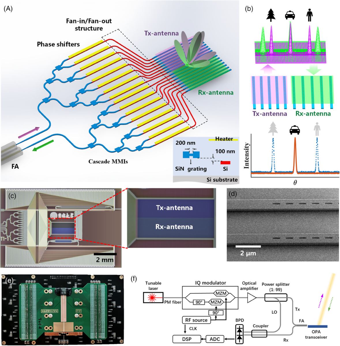
The operation principle of the Vernier antennas is shown in Figure 1b. For a uniform antenna array, when the pitch of grating antennas is greater than half a wavelength, the grating lobes rise in the FoV inevitably.[26] However, the direction of grating lobes can be manipulated by controlling the pitch among the grating antennas. Therefore, when the target beams of Tx- and Rx-antenna are aligned in one direction, other aliasing grating lobes will be misaligned. In this case, free aliasing can be achieved within the FoV by using the Vernier OPA structure. The Vernier grating antenna can effectively distinguish the target direction by generating a beat signal with high signal-to-noise ratio, leading to enhanced ranging performance, as shown in Figure 1b. The optical microscope image of the fabricated OPA is shown in Figure 1c. The zoom-in image of the Vernier grating antennas is exhibited in the inset. The tightly arranged Tx- and Rx-antennas enable OPA-based LiDAR to operate in quasi-coaxial system, relaxing the complicated optical alignment. An aliasing-free FoV is achieved through the vernier antenna arrays without any limitation in grating structure, which allows various grating structures.
In order to further expand the imaging FoV, we design a chained grating antenna that can emit a broad far-field profile with efficient and stable beam power over the FoV. It is beneficial to improve the imaging quality at the edge of FoV. Figure 1d is the SEM image of the designed chained grating antenna. As shown in Figure 1e, the OPA chip is packaged with a polarization-maintained fiber array (PMFA). The chip is wire-bonded to the circuit board, and controlled by a 256-channel DACs driver.[27] Each phase shifter is driven by a digital-to-analog converter (DAC) to implement phase control. Thereby, arbitrary wavefront modulation and beam scanning can be realized by electrical control. The solid-state 3D-imaging system realized by applying the Vernier OPA to the FMCW LiDAR system is shown in Figure 1f. A chirped laser is generated by externally modulating a tunable laser through an in-phase/quadrature modulator (IQM). The linear frequency chirp is synthesized by a radio frequency (RF) module. The light beam from the amplified chirp laser is emitted and steered by the OPA. Finally, the beat signal of received light and local light is detected by a balanced photodetector (BPD) followed by the processing by an analog-to-digital converter (ADC), and finally solved by digital signal processing(DSP).
In the case of OPA design, the peak power of the steering beam within FoV is modulated by the far-field profile of a single grating antenna. Hence, the beam power normally decreases as the steering angle increases.[16, 19] by narrowing the size of the antenna transceiver, the far-field profile can be expanded.[16] The light emission occurs in the etched region of the waveguide grating. Traditional gratings are usually fabricated by either etching on the waveguide surface with the same width as the waveguide or etching on both sides of the waveguide. Therefore, the width of the grating antenna is nearly equivalent to the width of the waveguide. Although enhanced optical confinement provided by thick Si waveguides can reduce the size of the antenna,[20] the improvement is not significant. In contrast, the proposed chained grating is featured by axially periodic micro-holes etched at the center of the waveguide. By reducing the width of the etched regions, the chained grating antenna can be effectively minimized, thereby significantly enlarging the far-field profile. The simulated far-field profiles in the case of chained grating with 200-nm etching width and traditional grating are shown in Figure 2a. The 3-dB width of far-field profile of proposed chained grating and traditional grating is ≈115°–77°, respectively. The chained grating exhibits a large far-field profile, enabling a broader FoV. The calculated far-field profiles of different etching width can be referred to the Figure S3 (Supporting Information).To obtain a broad far-field profile with a flat beam power distribution, we apply the chained grating antenna with 200-nm etching width to the OPA design. Compared with our previous work, the narrower etching width in chained grating provides a wider FoV. The main lobe beam power of the OPA is the intensity integral over the beam width, and more details of the calculation method can be referred to the Section S4 (Supporting Information). The calculated beam power at different steering angles is shown in Figure 2b. The 3-dB width of the beam power for the OPA with traditional SiN grating is ≈99°, while for the OPA with chained grating, it approaches 170°. The power degradation at the edge of FoVisalleviated by the broad far-field profile of chained grating and broadened divergence angle of the light beam. Therefore, a broad far-field profile with a slow roll-off power gives rise to a wide effective FoV for 3D imaging. The experimental result for the total beam power steered from −79° to 80° with an interval of 1° is shown in Figure 2c. The measured profile of main lobe beam power matches well with the simulation result. The fluctuation in beam power within the FoVarises from multiple reflections of light within the silica cladding before final emission. This process creates a Fabry-Perot cavity with an angle-dependent transmission response.[28] The abrupt decrease in power at −79°–80° is caused by the obstacle stuck on both sides of the OPA chip. At the edge of the FoV, the emitted beam travels nearly close to the surface of the chip, and thus the beam is mostly blocked by the wire-bonding electric package at both sides of the chip. It leads to a sudden drop in beam power. Therefore, the actual 3 dB width of the beam power of the fabricated OPA can be greater than 160°. It is found that the fabricated OPA exhibits less than 3 dB beam power variation within a record ≈160°FoV. In fact, a horizontal FoV close to 160° can already meet the vast majority of applications. More details of the beam quality within the FoV are demonstrated in Figure S5 (Supporting Information).
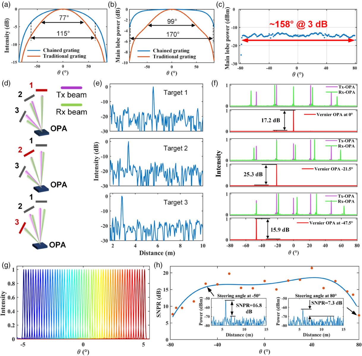
Next, the characterization of the Vernier OPA is conducted. According to our design, the target beam of the fabricated Tx-OPA is fixed at 0°, while the ±1st and ±2nd order grating lobes are located at ≈±21.5°–±47.5°, respectively. In order to verify the aliasing-free detection operation of the vernier transceiver, three targets are placed at 0°, −21.5°, and −47.5° at different distances, respectively as shown in Figure 2d. The Rx-OPA is electrically controlled to align to the fixed Tx-OPA in the three directions sequentially. The distances of three targets are resolved based on the beat signals shown in Figure 2e. It is found that the noise from the grating lobes is suppressed by the Vernier OPA significantly and only a clear beat signal appears during the ranging process. The measured normalized far fields of fabricated Tx- OPA and Rx-OPA over 180°are obtained by splicing images captured by an infrared camera, as shown in Figure 2f. The resultant far field of Vernier OPA is synthesized by overlapping the far fields of Tx-and Rx-OPA, as shown by the red line in Figure 2f. When the target beam of Rx-OPA is sequentially aligned to the main lobe, −1st and −2nd grating lobes of the Tx-OPA, the rest of the beams are stagged except for the alignment direction. In the resultant far field of Vernier OPA, there is only the target beam spikes within the FoV and the rest of the grating lobes are suppressed strongly. The suppression ratio for grating-lobe at steering angles of 0°, −21.5°, and −47.5°are 17.2, 25.3, and 15.9 dB, respectively. The Tx-OPA and Rx-OPA are simultaneously driven to achieve high-resolution alignment, resulting in 51 resolvable points spaced at intervals of 0.2° within a 10-degree range, and the resultant far fields are shown in Figure 2g.
The Vernier transceiver consists of two OPAs with different gating antenna pitches. When the main lobes of Tx- and Rx-OPA are aligned in an arbitrary direction, the other grating lobes are separated, thereby suppressed, facilitating a wide aliasing-free FoV. Furthermore, the proposed chained grating with a broad far-field profile prevents the significant degradation of beam power at the edge of FoV. This enables the Vernier OPA to maintain a high grating-lobe suppression ratio exceeding 10 dB even at an extreme steering angle of up to ±80°, as shown in Figure S7 (Supporting Information). More simulated and measured far fields of the fabricated OPA within a 160°FoV from −80° to 80°are shown in Figures S6 and S7 (Supporting Information). Therefore, the proposed Vernier architecture, equipped with the chained grating, enables the realization of an OPA-based LiDAR system with a horizontal FoV of 160°.
To clearly obtain the distance information for 3D imaging over an ultra-wide FoV, the beat signal at ranging measurement requires sufficiently high signal-to-noise pedestal ratios (SNPR). The broad far-field profile provided by the chained grating antennas can facilitate the Vernier OPA-based LiDAR to generate a high-SNPR beat signal. We measure the SNPR of beat signals within ≈160°FoV to evaluate the ranging performance of the OPA, as shown by the orange dots in Figure 2h. It is found that the SNPR of beat signals can be maintained above 10 dB when the steering angle is from −60° to 70°. The blue curve shown in Figure 2h is a fitting for the measured SNPR. The fitting curve of SNPR exhibits flat top from −60° to 70° steering angle, attributing to the flat beam power profile of chained grating antennas. The uniform beam quality lies profound foundation for high quality 3D imaging with ultra-wide FoV. Although the drop of SNPR occurs at both edges of the FoV, the beat signals still overtop the noise pedestals by 7.5 dB sufficiently high for 3D imaging. The degradation in the SNPRs of beat signals at the edges of the FoV is probably caused by the shrunk effective aperture of Rx-antenna at a grazing angle. In addition, the RF spectra for beat signals at the −50° and 80° steering angle are shown in the insets of Figure 2h., respectively. To sum up, the effective FoV provided by the proposed OPA-based LiDAR for 3D imaging can reach to 160°. The measurement setup and beat signals at different steering angles are demonstrated in Figure S8 (Supporting Information).
3 3D Imaging and Velocimetry
First, the solid-state OPA LiDAR system is applied to measure velocity and distance as shown in Figure 3. The bandwidth for the linear optical frequency chirp is 3 GHz, and the period for the up-and down-chirp time is 100 µs. The coherent LiDAR can directly measure the target velocity through Doppler frequency shifts of the received light.[29] The velocity-annotated 4D point clouds image of a rotating wheel is illustrated in Figure 3a. Figure 3b shows the measured beat signals for a static wheel and a rotating wheel. When the wheel stops, the beat signal of the up-chirp is consistent to that of down-chirp, indicating the measured distance is 3.9 m. When the wheel starts rotating, due to the Doppler shift of reflected light, the up-chirp and down-chirp signal shift in the opposite direction and the median of the two signals is the ranging distance of 3.9 m, and the difference of them can be solved as the velocity of 0.217 m s−1. We utilize the OPA to steer the light beam along the edge of the rotating wheel. The distance of 16 positions and corresponding projection of velocity in the direction of beam propagation are measured, as shown in Figure 3c. The velocity projection along the edge of the rotating wheel varies linearly from −0.3 to 0.3 m s−1. It is also found that there is a jitter in the outline of the wheel in the point clouds. It may be attributed to the instability of the system caused by the nonlinearity of chirp modulation and the linewidth of the laser.[30, 31] To quantify the accuracy of ranging, we conduct a 3D imaging of cardboard boxes with continuous surfaces and measure three positions on cardboard boxes by 100 times as shown in Figure S9 (Supporting Information). The standard deviation of the distance measurement is ≈5.5 mm.
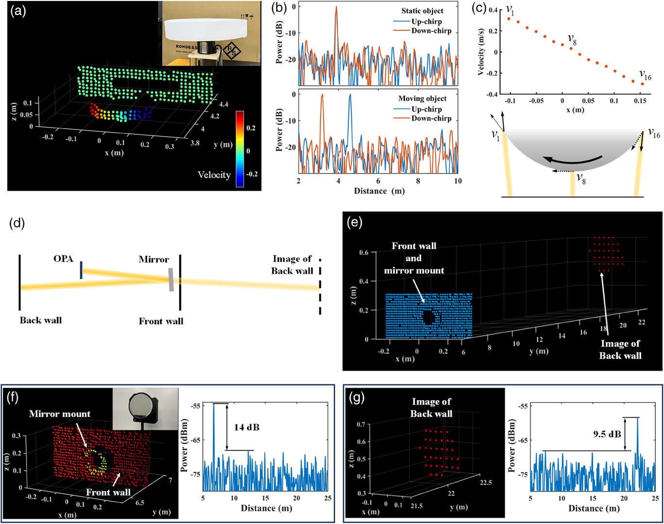
We also apply the OPA-based FMCW LiDAR system to distance measurement. A long optical path is constructed by placing a mirror in front of the front wall, as shown in Figure 3d.[10, 16] The OPA-based LiDAR can measure the distance to the back wall through the mirror. The 3D point clouds of the front wall, mirror mount, and image of back wall are shown in Figure 3e. The point clouds of the front and back walls are demonstrated in Figure 3f,g respectively to display details. The mirror mount is clearly observed in the point clouds and significantly distinguished from the front wall. The contour of the back wall point clouds is that of the mirror. The beat signals of ranging front wall and back wall are shown in Figure 3f,g, and the distances of the front wall and back wall can be resolved as 6.75–22.15 m, respectively. In the experiment, the input power to the OPA is 25 dBm and thus a ≈11 dBm main beam is emitted from the OPA. The SNPRs of the generated beat signals for targets at 6.75–22.15 m are ≈14–9.5 dB, respectively. We further investigated the detection capability of the OPA-based FMCW LiDAR system. Initially, we measured the minimum detectable power of the FMCW device to be -95 dBm. Subsequently, with an input power of 30 dBm to the OPA, the detectable distance for the objects with 10% reflectivity exceeds 20 m. More details of measurement can be referred to the Section S10 (Supporting Information). The range of LiDAR increases proportionally to the square root of both the antenna aperture and transmission power.[32] The scale of OPA based on the advanced SiN-on-SOI photonics platform can be expanded to thousands of channels, enhancing the ranging distance significantly. Furthermore, photonics integrated circuits based on SiN-on-SOI platform can withstand input power exceeding 37 dBm,[11] enabling longer ranging.
Last but not least, we demonstrate the OPA-based solid-state LiDAR with an ultra-wide FoV in 3D imaging. A high-resolution 3D point clouds exceeding 135° with more than 7000 resolvable points including 400 horizontal resolvable points and 18 vertical resolvable pointsas shown in Figure 4a.The inset shows the corresponding photo of the real scene. Note that the horizontal angle of the proposed OPA-LiDAR is not limited to 135°. Furthermore, we have demonstrated the horizontal steering angle of the OPA-based LiDAR can be improved to achieve 3D imaging with a record wide 160°FoV. The corresponding 3D point-clouds image is illustrated in the Section S11 (Supporting Information). Limited by the bandwidth of Erbium-Doped Fiber Amplifier (EDFA), the vertical FoV is confined to ≈3° within a wavelength range of 42 nm. A wider bandwidth optical amplifier can enable a broader vertical FoV to be achieved.[10]
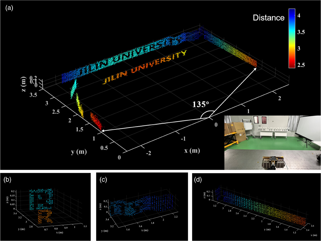
The 3D point cloud clearly exhibits a series of letters ‘JILIN UNIVERSITY’ located at the middle area of the FoV, with a white curtain wall on the right and scattered cardboard boxes on the left. OPA owns flexible angular resolution, which can provide more detailed 3D images by increasing the angular resolution. Complex objects require extremely high angular resolution scanning. For objects with simple outlines, such as walls, moderate resolution can also clearly display the outlines. Therefore, the area where the letters are located is scanned with a 0.25° angle resolution to better display details, while the walls and cardboard boxes with simple outlines are scanned with a 0.5° angle resolution. The outline of the letters can be clearly distinguished, and the shadows of the letters on the back wall are also clearly presented. The point cloud image of the letter ‘R’ is enlarged and shown in Figure 4b. The outline of the letter R is clearly delineated by ≈100 points. The ripples of the window curtains are clearly displayed in the 3D point clouds, as shown in Figure 4c. As shown in Figure 4d, the point clouds of the right curtain wall are also specially displayed. The gradual change in distance from ≈2.5 to 4.2 m can be accurately observed through the changes in colors. By virtue of the uniform beam power profile supported by the proposed chained antenna, the OPA based LiDAR exhibits superior and uniform quality of 3D imaging over the whole FoV. As shown in Figure 4a, we can barely observe blind spots in the point clouds over 135° horizontal FoV.To our best knowledge, this is the first time that OPA solid-state LiDAR has demonstrated 3D imaging exceeding 160°. The OPA-based FMCW LiDAR system can potentially process more than the demonstrated 7000 points in 3D imaging.
4 Discussion
The comparison among various on-chip solid-state (or semi-solid-state) platforms for 3D imaging is illustrated in Table 1. It is shown that the proposed Vernier OPA-based LiDAR system exhibits outperformance in terms of monolithic integration, easy optical alignment, and wide imaging FoV. In this work, we have demonstrated a solid-state OPA-based LiDAR with a record wide horizontal FoV of 160° for 3D imaging. The chained grating antenna is proposed to broaden the far-field profile of the OPA. Therefore, the beam power variation of OPA is less than 3-dB within 160°FoV, providing sufficient beam power even at the edge of FoV. On the other hand, two chained grating antenna arrays with different grating pitch are integrated monolithically to form a 256-channel Vernier transceiver, leading to an aliasing-free fullFoV. The architecture of combining a wide far-field profile antenna and Vernier OPA enables the OPA based LiDAR to prove outstanding 3D imaging quality with an impressive wide horizontal FoV of 160°. Alternatively, the amounts of resolvable points at athorizontal and vertical dimensions can be scaled up by finer phase control and wavelength tuning.It can guarantee high-angle-resolution beam steering. To the best of our knowledge, it has been the widest FoV for 3D imaging based on OPA-based LiDAR so far. In addition, the Vernier OPA is also applied to the FMCW ranging system for velocity and distance measurement. The velocity-annotated 4D point clouds and distance measurements up to 22 m indoors are demonstrated. The precision of ranging is 5.5 mm.
| Year | Mechanism | Tx/Rx alignment | Integration | Horizontal imaging FoV |
| 2019 [10] | OPA | Non-coaxial | Separated chips | 56° |
| 2020 [6] | FPA | Non-coaxial | Separated chips | -a) |
| 2022 [9] | MEMS-based FPSA | Coaxial | Monolithic | 16° |
| 2022 [11] | OPA | Coaxial | Monolithic | 100° |
| This work | Venier OPA | Coaxial | Monolithic | 160° |
- a) No accurate data available.
It is worth of mentioning that the closely spaced Tx- and Rx-antenna is beneficial to the optical imaging system. In particular, the Tx- and Rx-antennas are located close to form a quasi-coaxial system, avoiding complex alignment between transmitter and receiver.[6, 10] Moreover, the separation of transmitted and received light in the link helps to avoid unexpected interference from interface reflection. The entire system does not contain any lenses or optical mechanical structures, thus can be miniaturized to a compact, low-cost cost, and high-reliability platform.
The proposed OPA only demonstrated a verticalFoV of ≈3°, but this is not limited by the Vernier OPA architecture and the chained grating antenna. In fact, the vertical steering efficiency mainly depends on the chromatic dispersion of material. The wavelength steering efficiency of SiN waveguide grating is typically 0.07°/nm,[33, 34] while for a Si waveguide grating, the efficiency can reach 0.15°/nm.[10] The proposed Vernier transceiver architecture and chained grating are not dependent on material characteristics. They can also be applied to Si waveguide gratings to achieve larger vertical steering efficiency.
The SOI platform has commonly been a competitive alternative for OPA fabrication, since strong optical confinement for dense grating antenna arrays. Hence, the aliasing free FoV can be expanded effectively. However, the power handling capability of silicon is less sufficient for the application in OPA system. Rather than relying on material characteristics, we propose a novel architecture for OPA chip design to achieve wide imaging FoV with a flat beam power profile. The proposed structure is suitable to various material platforms for the fabrication of high performance OPA.[35, 36]
In this work,a fabricated OPA chip with 256 elements is used to demonstrate 3D imaging of indoor scene at only ≈22 m. Nevertheless,by virtue of advanced SiN-on-SOI platform and high-power handling of SiN waveguides, LiDAR for longer distances can be achieved by enlarging the OPA scale of channels and increasing input power. The range of LiDAR scales as the square root of the antenna aperture and transmission power.[32] Therefore, our architecture can potentially operate at ranges of exceeding200 m by scaling the proposed monolithic OPA transceiver to thousands of elements and boosting the input power to more than 30 dBm.
Acknowledgements
This work is supported by the National Natural Science Foundation Of China under Grants nos. 62090054, 61934003, 62105174, and 62105173; the National Key R&D Program of China under Grants No. 2022YFB2804504; the Major Scientific and Technological program of Jilin Province under Grants No. 20210301014GX. the Jilin Provincial Development and Reform Commission project (2020C056). The Program for Jilin University Science and Technology Innovative Research Team (JLUSTIRT, 2021TD-39)
Conflict of Interest
The authors declare no conflict of interest.
Author Contributions
B.C., Y.L., and J.S. led this work. B.C., Y.L., Q.N., and Q.X. performed the experiments and analyzed the results. B.C., M.T., and Z.W. built the control system. G.L. supports the wafer fabrication process. B.C., Y.L., and J.S. prepared the paper. B.C., Q.X., Y.L., Q.N., G. L., and J.S. revised the paper.
Appendix
Simulation
Simulation results of the far-field profile of grating antenna are done by FDTD (ANSYS LUMERICAL, USA). The simulation of the far fields of OPAs is calculated by the superposition of the diffraction fields generated by antennas.
Measurement
Beam Power WiSthin the FOV
The main beam power is measured by a free space power meter (S122C, Thorlabs, USA). The OPA and controller are placed on the rotation stage and a power meter is placed in a fixed position. By controlling the rotation of the rotation stage and the beam steering of OPA, beams of different angles are aligned to the power meter to obtain the power of each steering angle in the FOV.
Far Fields of Vernier OPA
The far fields of Tx- and Rx-OPA are measured by an infrared camera (Bobcat 640 GigE, Xenics, Belgium). Due to the limited FOV of the infrared camera, the far fields of OPA in full FOV cannot be directly obtained. We place the OPA on a motorized rotation stage and place the observation screen properly. The infrared camera is adjusted to exactly cover the 10° range of far fields of OPA. We rotate the rotation stage with 10° intervals, capture images through the camera, and finally splice the images to obtain the far fields of Tx- and Rx-OPA in the full FOV. The resultant far fields of Vernier OPA are synthesized by overlapping the measured far fields of Tx-and Rx-OPA.
OPA-Based LiDAR System
A tunable laser (TSL550, Santec, Japan), an IQ modulator, and a chirp-frequency-modulation RF module are used to form an FMCW laser. The chirp bandwidth is 3 GHz, and the up- and down-chirp lengths are 100 µs. The Vernier OPA transceiver completes the emission of light and reception of reflected light. The beat signals of received light and local light are sampled by an oscilloscope (MSO64B, Tektronix, USA), and finally solved by DSP in PC software.