


Abstract
Terahertz (THz) communication is an up-and-coming technology for the sixth-generation wireless network. The realization of ultra-high-speed THz communication requires the combination of multi-dimensional multiplexing schemes, including polarization division multiplexing (PDM), mode division multiplexing (MDM), and wavelength division multiplexing, to increase channel capacity. However, most existing devices for MDM in the THz regime are single-purpose and incapable of multi-dimensional modulation. Here, all-dielectric metasurfaces are designed for 2D multiplexing/demultiplexing, which takes the lead in combining orbital angular momentum (OAM) MDM and PDM in the THz regime. The multi-functional wavefront phase modulations and interleaved meta-atom arrangements are used to realize polarization-selective multichannel OAM mode (de)multiplexing, in which the linear-polarized 4-channel and circular-polarized 6-channel demultiplexing are experimentally demonstrated. Between different linear-polarized channels, the measured maximum crosstalk is −16.88 dB, and the isolation of each channel can be greater than 10 dB in a range wider than 0.1 THz. This study paves the way for multi-dimensional multiplexing in the THz regime, which may benefit extremely high-capacity and integrated THz communication systems. The proposed design strategy is readily applied to multi-functional metasurfaces for microwaves and far infrared light, facilitating the development of multiplexing technology and OAM-related applications.
Introduction
Terahertz (THz) photonics is an emerging field with significant potential for the 6th generation wireless systems (6G), enabling broadband features and good directivity.[1-3] The large capacity and high-speed 6G communication need THz devices for high-performance beam steering,[4, 5] modulation,[6, 7] and multiplexing. More recently, a series of studies on THz multiplexing, including polarization division multiplexing (PDM), wavelength division multiplexing (WDM), and mode division multiplexing (MDM), have received considerable interest.[8-11] Among these, MDM that explores the orthogonality of modes[12-14] can establish multiple distinguishable data paths using the orthogonal orbital angular momentum (OAM) modes.[15] The OAM determines the spiral phase front of the vortex beam proportional to exp(ilφ), here φ is the azimuthal angle, l represents the topological charge, and the value of l can take any integer. OAM-MDM has been extensively discussed in optical and quantum communications.[16-19] In recent years, it has gradually garnered attention as an efficient candidate to increase the spectral efficiency of communication systems in the THz regime.[20]
The realization of high-quality MDM relies on the convenient and efficient (de)multiplexer for the orthogonal modes.[21-25] Spatial light modulators and spiral phase plates are two straightforward methods for OAM mode conversion.[26, 27] However, multiple converters and additional beam combiners are required to realize coaxial transmission of orthogonal modes for (de)multiplexing. Metasurfaces composed of sub-wavelength meta-atoms exhibit extraordinary wavefront manipulation applications such as abnormal refraction, beam modulation, perfect absorption, and mode conversion,[28-32] providing a customizable design method for the high-performance OAM mode generators and multiplexers.[33-38] Notably, by taking advantage of shared-aperture arrangement[39] and polarization-dependent meta-atoms,[40] a single metasurface can implement the 2D multiplexing of polarization and mode to increase the spectral efficiency immensely.[41-44] Meanwhile, the deflection and focusing of the converted beam can also be integrated into this metasurface, which can significantly benefit the compactness and efficiency of the MDM system.[45] Recent pioneering reports in the THz regime have shown encouraging advances in metasurfaces for multichannel vortex beam generation[46-48] and OAM mode multiplexing.[49, 50] Moreover, combining OAM-based MDM and PDM can enhance spectral efficiency and system integration, enabling THz communications to support massive device connections and achieve ultra-high-rate data transmission. Significantly, the working bandwidth of the multi-functional metasurfaces used in multi-dimensional multiplexing and the crosstalk between adjacent channels have not been investigated, which is vital to compact THz wireless communication systems with extremely high data capacity.
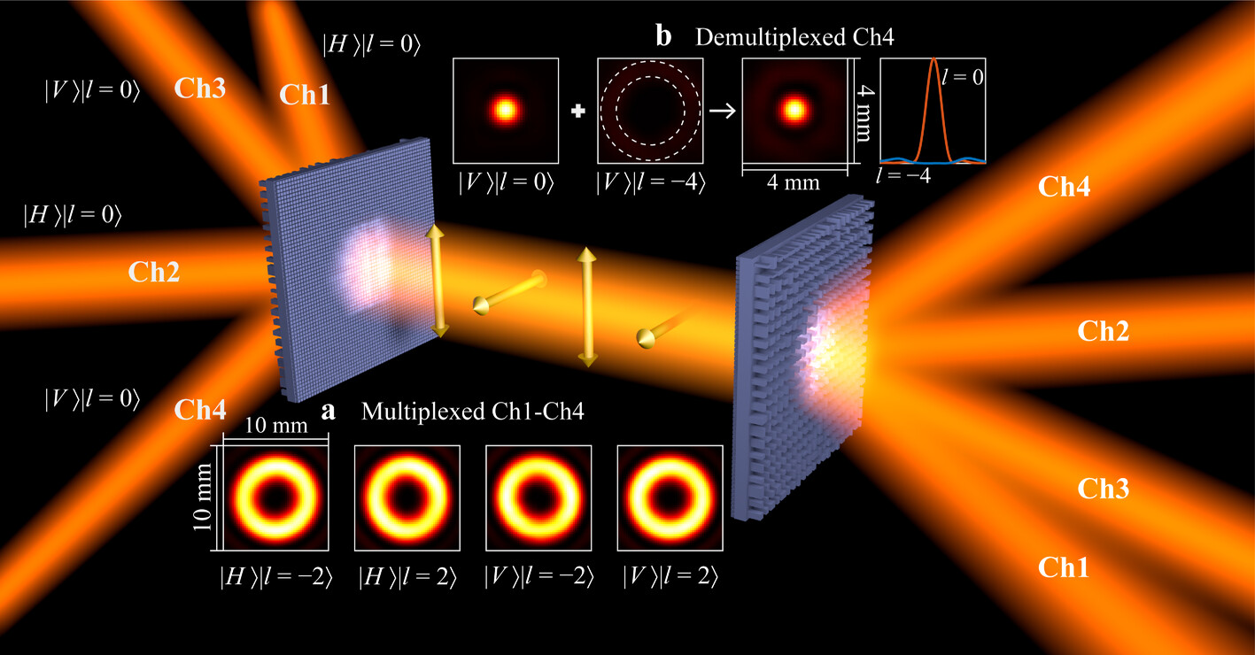
Here, we propose all-dielectric metasurfaces for multi-dimensional multiplexing and demultiplexing in the THz regime. The multi-functional phase-modulated metasurfaces function as versatile (de)multiplexers in the MDM and PDM systems. As shown in Figure 1, the Gaussian beams with different incident angles and polarizations are first converted to coaxially transmitted vortex beams with different OAM modes, and each incident beam serves as a data-carrying channel for information transmission. At the receiving terminal, the demultiplexer recovers the coaxial OAM modes to the corresponding Gaussian beams and focuses the demultiplexed beams on different positions. In the experiment, we demonstrated the demultiplexing process of 4-channel and 6-channel coaxial beams using multi-functional metasurfaces. The low crosstalk and high isolation of the demultiplexed channels show good performance of the fabricated metasurface samples at 0.75 THz. Notably, both two types of metasurfaces with linearly polarized (LP) responses and circularly polarized (CP) responses exhibit broadband responses and have the potential to be compatible with integrated WDM. The multi-functional metasurfaces demonstrated here can benefit the development of compact and broadband platforms for multi-dimensional multiplexing in the THz communication system.
Results
2.1 Preparation of Multi-Functional Metasurfaces
Figure 1 illustrates 4-channel 2D multiplexing and demultiplexing based on a pair of multi-functional metasurfaces. Two horizontally polarized (HP) and two vertically polarized (VP) Gaussian beams with various incident angles are converted into high-order OAM beams by the designed metasurface. Here, the state of the four orthogonal channels can be described by
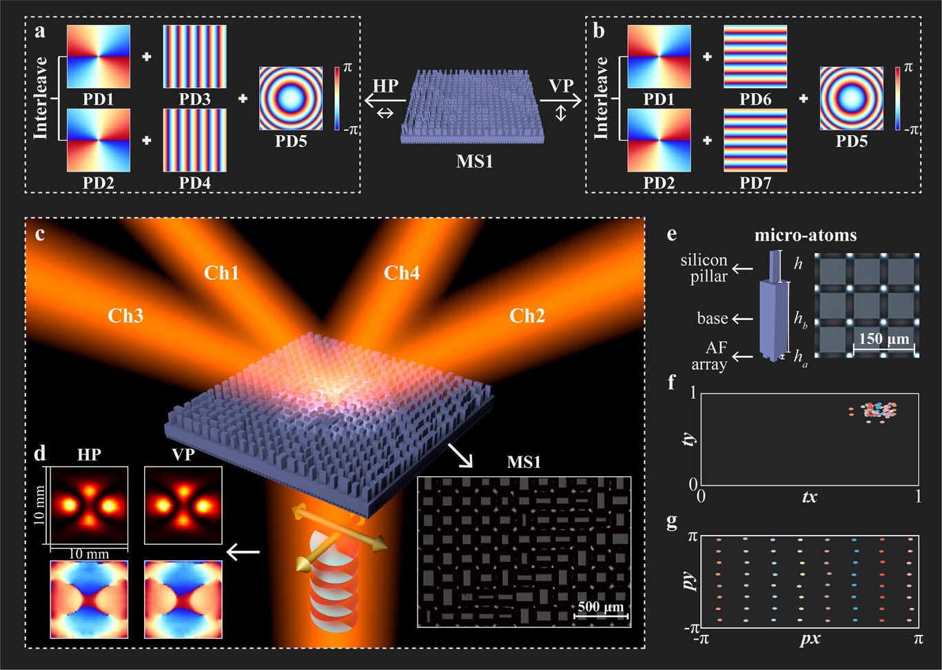
To obtain the different transmission responses for HP and VP components, the phase modulation of the metasurface at each point should satisfy the ΦHP and ΦVP in the two formulas above. As shown in Figure 2e, we used polarization-dependent silicon meta-atoms to compose the metasurface. The high-resistive silicon wafer exhibits a non-dispersive refractive index (∼3.45) and low absorption loss in the THz band. Sixty-four meta-atoms with a period of 160 µm (0.4 λ at 0.75 THz) were selected to achieve independent phase modulation for HP and VP with a phase interval of 45°. Details of the chosen pillars can be seen in Table S1 (Supporting Information). The metasurface contains three layers: a silicon pillar with a thickness of h = 260 µm, a 688-µm-thick silicon substrate, and a periodic anti-reflection layer with ha = 52 µm thickness. As shown in the right image of Figure 2e, the anti-reflection layer[51] consists of the periodic quadrate pillars with side length lx = ly = 48 µm and the period p = 63 µm. The phase accumulation of the selected meta-atoms under HP and VP incidence simulated by CST Microwave Studio is shown in Figure 2g. Figure 2f shows the simulated transmission amplitude of the selected meta-atoms. The average tx(ty) of the chosen meta-atoms is 0.815, and the transmissivity of the ordinary silicon wafer is ≈0.7, which indicates that the anti-reflection layer can effectively improve transmission efficiency. We fabricated the proposed metasurface by double-sided registration lithography and deep reactive ion etching. The details can be found in the “Method” section. For the fabricated MS1 sample, the optical image of the upper layer is shown in the lower right corner of Figure 2c.
2.2 Two-Dimension Demultiplexer with LP Responses
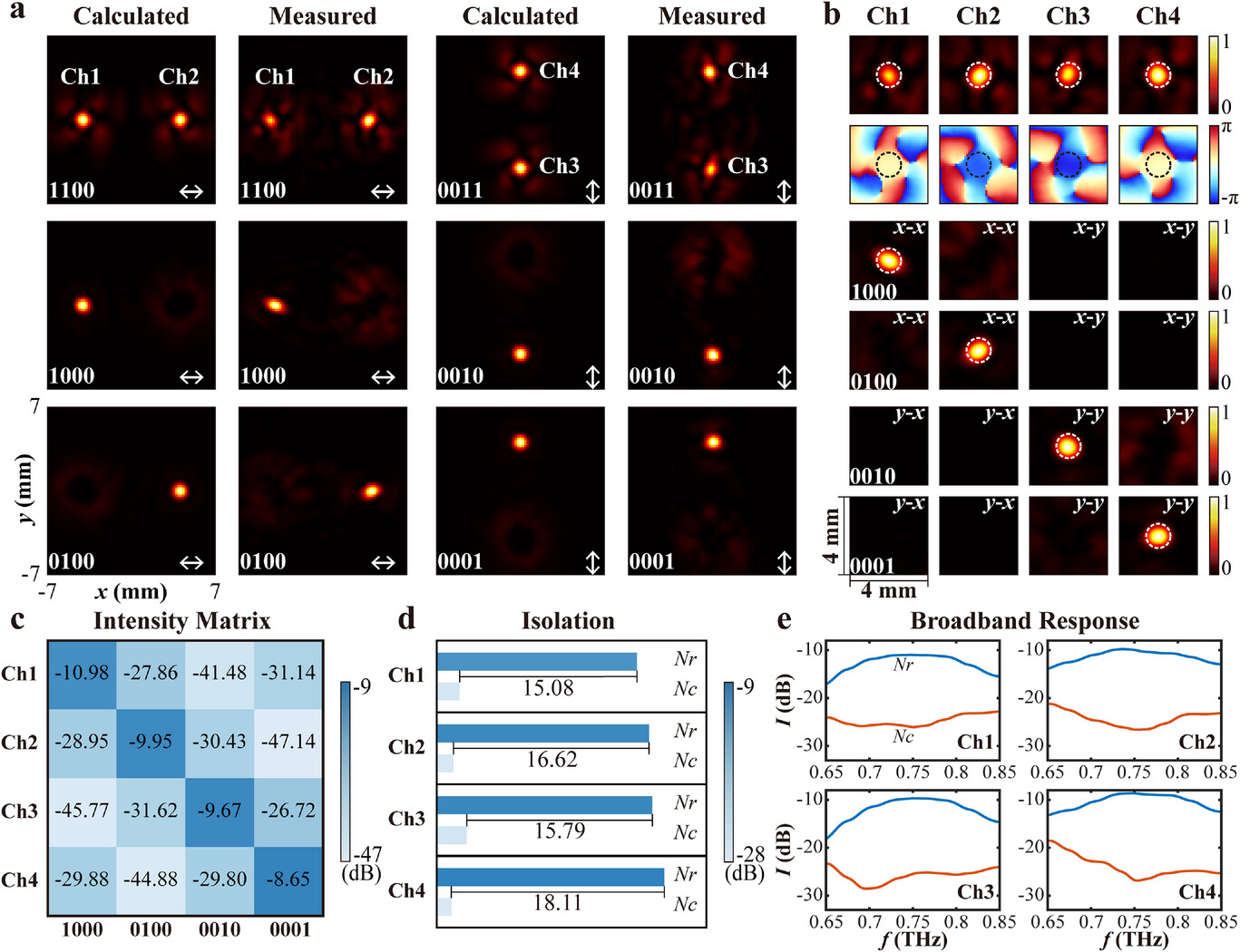
The characteristics of the fabricated metasurfaces were experimentally investigated by the THz near-field time-domain spectroscopy (NF-TDS) system. Details of the experimental setup are shown in Figure S2 (Supporting Information). Since it was difficult to tilt the transmit antenna in our NF-TDS system, we fabricated the mode converter to replace the multiplexer used for oblique incidence, which can convert the normal-incident THz beam into OAM beams with the topological charge of l = ±2, the details of the design method are shown in Section S.4 (Supporting Information). The intensity and phase distributions of converted superimposed vortex beams with HP and VP can be seen in Figure 2d. We use the fabricated multi-functional metasurfaces as the 2D demultiplexer. Figure 3 shows the measured and calculated results of demultiplexed channels at four receive positions, verifying the 2D modulation of the metasurface. A 4-bit binary code is used to simulate incident beams that carry different information. Out of the demultiplexer, the spatially co-propagated OAM beams carried different information that could be recovered to Gaussian beams and be focused to four positions, as shown in Figure 3a. The result scanned by the NF-TDS system in Figure 3a is the x-y plane perpendicular to the z-axis. But in practice, the detector should be placed in the plane perpendicular to the wavevector of the demultiplexed beam. Here, we process the measured data by RS integration to obtain the intensity and phase distributions in the plane perpendicular to the wavevector of the demultiplexed channels. The results for each channel are shown in Figure 3b, and the data processing details are in Section S.5 (Supporting Information). When the incident beams carry 1100, the clear focus spots and uniform phase distributions can be observed in two symmetric positions on the x-axis. If the incident beams carry 0011, the two focus spots can be seen on the y-axis.
Based on the measurement results in Figure 3b, we can quantitatively analyze the crosstalk and isolation of four channels, where the aperture of the receiver is set to 1.36 mm (white dashed circles in the figure), the same as the diameter (calculated by 1/e2) of the focused spot. The intensity matrix of the four demultiplexed channels is shown in Figure 3c, where the values are calculated by NdB = 10·lg (Ir/Ii), Ir is the intensity of the correct-demultiplexed Gaussian beam within the receiving aperture, and Ii represents the intensity of the corresponding incident beam. The diagonal of the matrix is the value of the correct-demultiplexed beam, and the others are crosstalk. The maximum crosstalk among all channels is −16.88 dB. The isolation of each channel is shown in Figure 3d, which is calculated by Nis = Nr – Nc, Nr is the intensity of the correct-demultiplexed beam in the diagonal of the intensity matrix. Nc = 10·lg (Ic/Ii), Ic represents the sum of the intensities of all crosstalk aroused by incorrect-demultiplexed beam within the receive aperture, and the measured isolation of the demultiplexed channels at 0.75 THz can be greater than 15.08 dB. We also analyzed the performance of the designed devices over the broadband range of 0.65–0.85 THz based on the measured results. It is worth mentioning that we used broadband mode convertors in the experiment, and the normalized intensity of all incident OAM modes in the measured frequency range is greater than 83%. The details of incident vortex beams can be found in Figure S5 (Supporting Information). The isolation of the four channels in the whole interested range is shown in Figure 3e, while the crosstalk is analyzed in Section S.7 (Supporting Information). Due to the dispersion, the wavelength deviation will decrease in the received intensity. However, the proposed metasurface still exhibits wideband performance. The 3 dB bandwidth of all correct-demultiplexed channels is 0.13 THz, and the isolation of each channel can be greater than 10 dB over a range of 0.15 THz. Considering that isolation and insertion loss are two critical factors in multiplexing systems, we defined the adequate working bandwidth (AWB) of the devices as the frequency range in which the received energy attenuates less than 3 dB with respect to the center frequency and the isolation of each channel is greater than 10 dB. Thus, the AWB of the designed MS1 is 0.13 THz. The results indicate that the proposed 2D demultiplexer is promising for THz communication compatible with WDM. As two cascaded metasurfaces are adopted in our MDM strategy, the misalignment issues may influence the performance of the devices. We provide a theoretical analysis and discussion on this issue in Section S.8 (Supporting Information). The calculated results show that as long as the displacement is less than ±2 mm (31% of the side length of the metasurface), the decrease of received intensity and isolation can be less than 3 dB and 8 dB respectively, indicating that the multiplexing system can still perform well under minor displacement. Meanwhile, the calculated results shown that the devices can be robust to the minor rotation if the diffraction orders are designed to be symmetric.
2.3 Two-Dimension Demultiplexer with CP Responses
The HP and VP are two essential and commonly used orthogonal polarization states for the PDM technique used in optical communications. Besides HP and VP, the left-circular polarized (LCP) and right-circular polarized (RCP) components also can be used as two orthogonal polarization channels. Using the circularly polarized components can decrease the alignment difficulty of the polarization coordinates of the transmitter and the receiver, and the polarization degree of a circularly polarized beam can maintain better performance in the free space transmission compared with that of a linearly polarized beam.[54] Therefore, we designed MS2 with CP responses. Similar to MS1, the designed MS2 needs to provide two independent phase profiles for the LCP and RCP components, and the transmission functions of ΦLCP and ΦRCP are the same as ΦHP and ΦVP we mentioned above, respectively. Here, we obtain the target phase profiles by combining geometric phase and propagation phase modulation[55] in the design method. The phase modulation of the metasurface at each point should satisfy ΦLCP = exp[i(φl)] = exp[i(φp + φg)] and ΦRCP = exp[i(φr)] = exp[i(φp − φg)], here φp and φg represent propagation phase and geometric phase, respectively. To design a metasurface with arbitrary phase distribution φl and φr, the propagation phase at each point should satisfy φp(x, y) = (φl + φr)/2, and the orientation angle ?? is defined by ??(x, y) = φg/2 = (φl − φr)/4. As shown in Figure 4c, we used the anisotropic silicon pillars to compose the metasurface. The image of the fabricated MS2 sample is shown in the bottom right corner of Figure 4a. We selected eight pillars with a propagation phase interval of 45°, four of them are displayed in Figure 4d. The other four structures can be obtained by rotating these four pillars with an angle of 90°. For the chosen meta-atoms, the phase difference between the geometric phase φx and φy is very close to π, thereby implementing efficient conversion of the two orthogonally circular polarizations, and the average conversion efficiency ηlr(ηrl) is 0.8244. Figure 4e shows the geometric phase of eight meta-atoms, which illustrates that the phase delay φl can cover the range of 0–2π when rotating the pillars from 0 to π. The details of the selected meta-atoms are shown in Table S2 (Supporting Information).
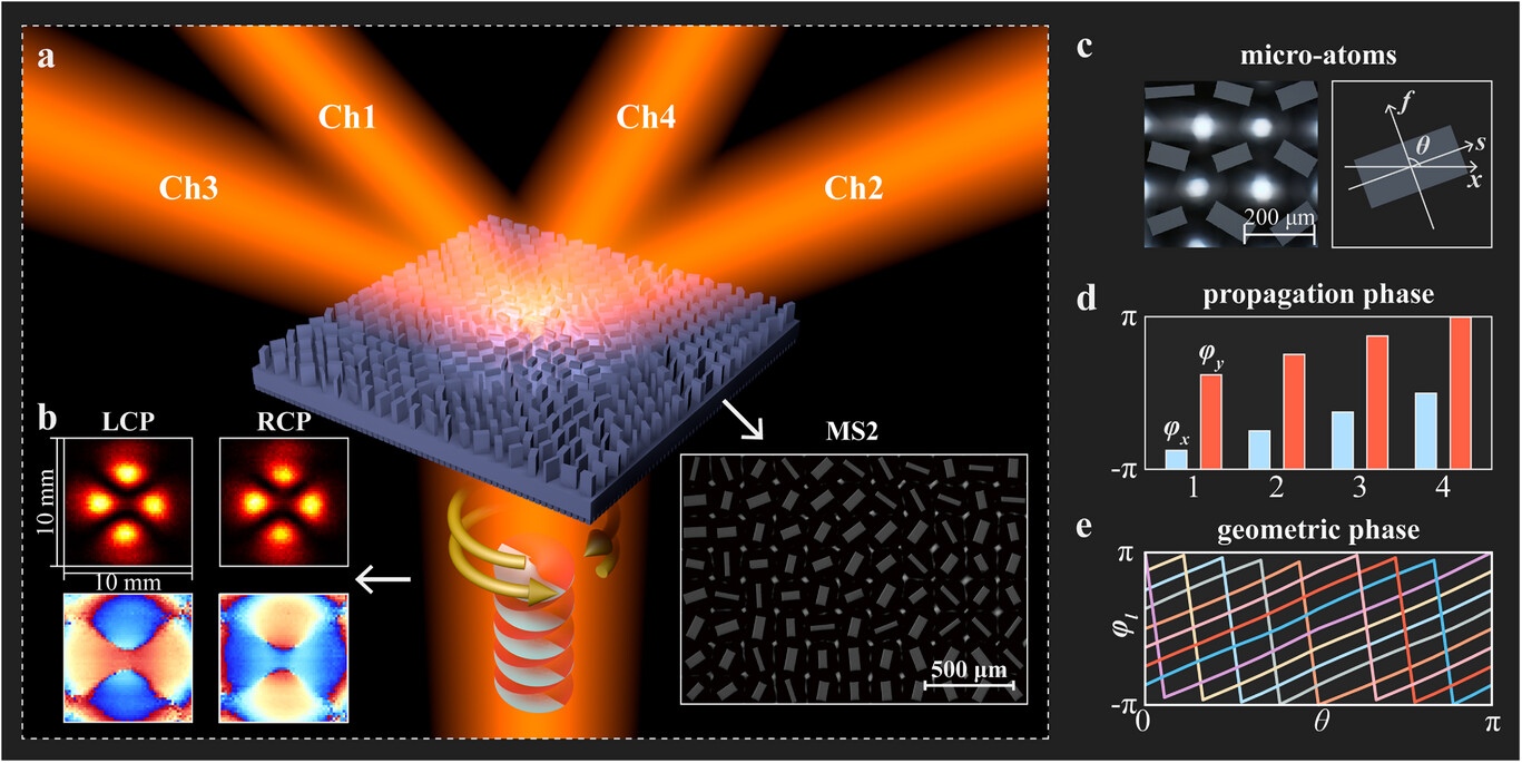
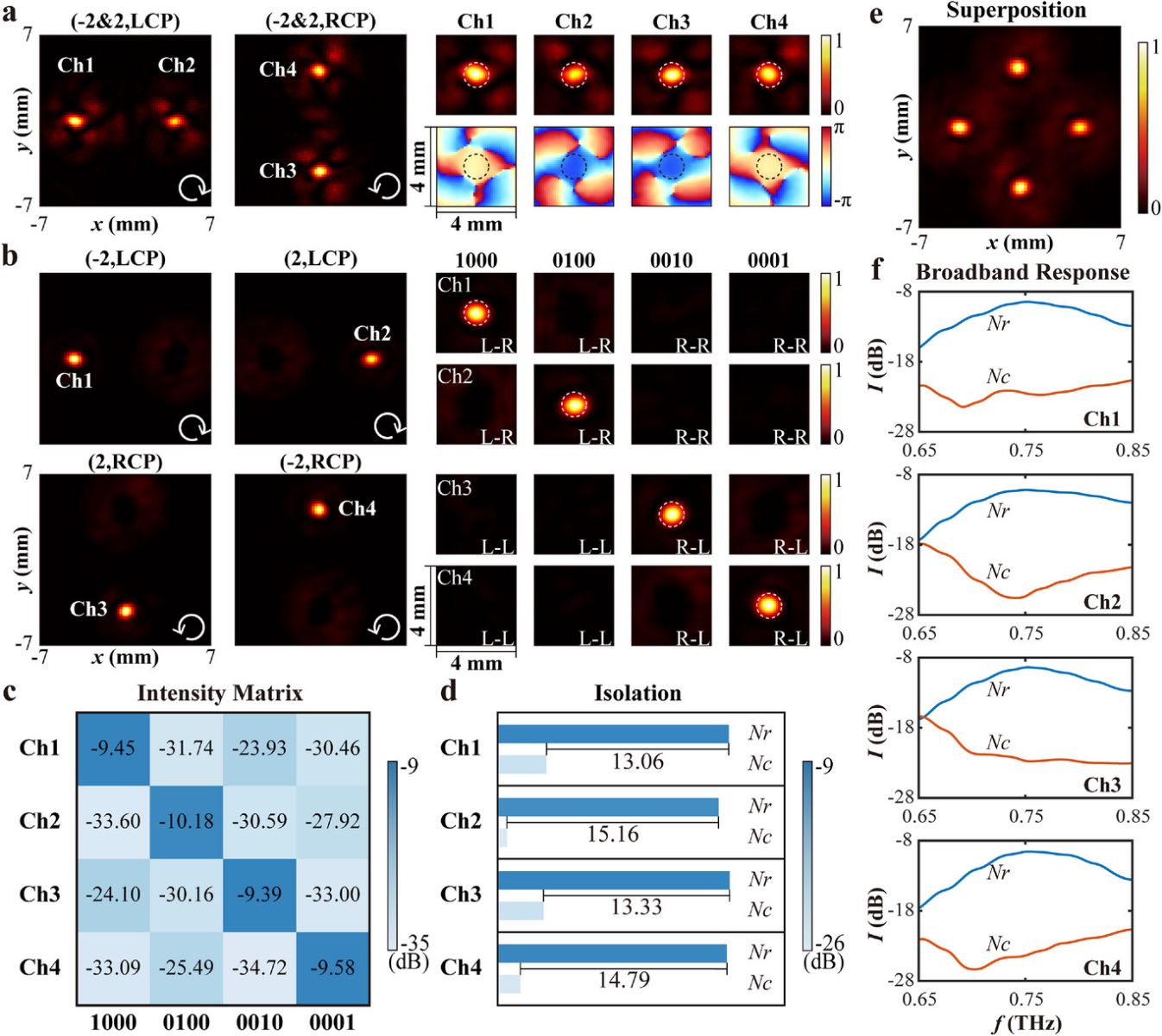
Figure 4b illustrates the measured intensity and phase distributions of the coaxial beams with superimposed OAM modes of l = ±2 for LCP and RCP, respectively, which was obtained by another mode converter. As illustrated in Figure 4a, MS2 is used as a 2D demultiplexer with CP responses, and the intensity distributions of the demultiplexed channels are shown in Figure 5a. The right of Figure 5a shows the intensity and phase distribution at the focused positions of the four channels, demonstrating that the OAM modes with different polarizations are successfully demultiplexed into spatially separated fundamental Gaussian modes by the MS2. Figure 5b shows the measured intensity distribution in demultiplexed focal plane illuminated by different OAM beams, respectively, and the intensity distributions at four focal positions in the plane perpendicular to the wavevector of correct-demultiplexed beams are shown on the right of Figure 5b. Figure 5c represents the intensity matrix of the four demultiplexed channels. It can be seen that the crosstalk between the orthogonal polarization channels is greater than that between different OAM mode channels with the same polarization. The former of crosstalk can be attributed to fabrication errors because the small deviation of element size will cause the reduction of polarization conversion efficiency, and the incomplete conversion of energy can increase the crosstalk. However, the fabricated MS2 still shows good performance. The maximum crosstalk among all channels is −14.48 dB, and the measured isolation of the channels is above 13.06 dB (as shown in Figure 5d). Figure 5e is obtained by superposing the intensity distribution in the focal plane of demultiplexed beams under four incident vortex beams carrying the codes 1000, 0100, 0010, and 0001, respectively. We also evaluate the performance of the designed MS2 over the broadband range of 0.65–0.85 THz, and details of the broadband incident vortex beams are shown in Figure S6 (Supporting Information). As shown in Figure 5f, the 3 dB bandwidth of the demultiplexed channels is 0.13 THz, and the measured isolation of each channel can be greater than 10 dB over a range of 0.12 THz, which means that the AWB of MS2 can exceed 0.1 THz. These indicate that the designed metasurface can perform 2D demultiplexing in a broadband regime.
Discussion
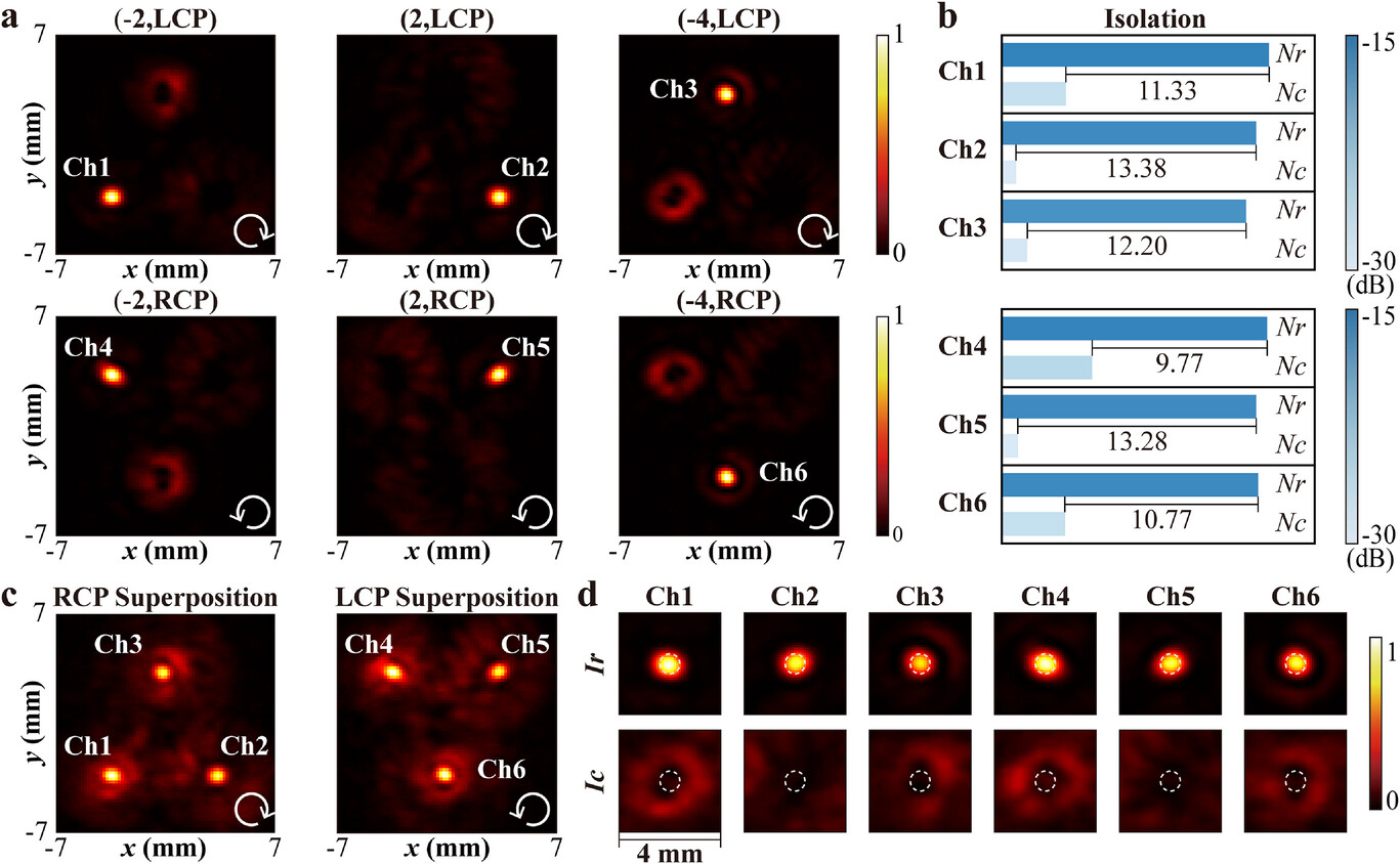
The design method we used here can be extended to realize multiplexing and demultiplexing for more OAM channels or other orthogonal mode channels, such as Herimite-Gaussian modes and vector modes. As a proof of concept, we designed MS3 for 6-channel multi-dimensional demultiplexing, and the states of the six coaxial channels can be described by
Conclusion
In conclusion, we proposed a multi-functional metasurface to realize the 2D MDM-PDM in the THz domain. 4-channel LP demultiplexing and 6-channel CP demultiplexing were experimentally demonstrated by the NF-TDS system. For the 4-channel LP demultiplexing, a low crosstalk of −16.88 dB between different channels is achieved. Moreover, the 3 dB bandwidth of the metasurfaces is 0.13 THz, and the measured isolation of each channel can be greater than 10 dB over a range of 0.1 THz, which indicates that they have great potential to be compatible with WDM. This work provides an efficient and compact platform for integrated THz MDM and PDM, and the results will help to pave the way for multi-dimensional multiplexing in high-capacity THz communication systems.
Experimental Section
Fabrication Steps
The fabrication of the metasurface sample can be divided into three steps. First, a 3-µm-thick AZ4620 photoresist is spin-coating on the 1-mm-thick silicon wafer, prebaked at 120 °C for 120 s, and subsequently exposed through UV to pattern the features of the designed meta-atoms in the mask aligner (SUSS MA4). The patterns are revealed after the development process in AZ400K liquid for 18 seconds. It is worth mentioning that the alignment marks on the photomask are used to calibrate the lithography area for double-layer processing. Next, the silicon sample is etched by the inductively coupled plasma reactive ion etching system with Bosch technology. This process consists of passivation and etching. During each period, we use SF6 gas to etch the silicon for 4 s and C4F8 gas to deposit fluorocarbon protective polymer for 2.2 s. The above period is repeated until the required etching depth is achieved. Finally, we removed the remaining photoresist with an acetone solution and cleand the silicon wafer with DI water.