


 View fulltext

2024
Volume: 53 Issue 5
25 Article(s)

Meng Li, Jiaxin Li, Xinqian Guo, Decheng Wu, and Suyue Liu
The physical processes occurring in the atmospheric boundary layer are important factors in the formation of large scale weather and climate. Therefore, detecting the refined structure of the boundary layer helps to understand the physical evolution characteristics of the atmospheric boundary layer, and the impact mechanism of complex boundary layer structures on atmospheric pollution processes. In order to study the mechanism of air pollution, air pollution forecasting is carried out, ensure ground traffic and aviation safety. It is necessary to establish a reasonable mathematical model to study the laws of changes in the Earth's climate environment system and make predictions, and to have a very deep understanding of the atmospheric boundary layer. At present, fine observation within the boundary layer is mainly obtained through in-situ measurement methods, using wavelet analysis methods to obtain corresponding coherent structures and scale features from in-situ measurement data. The scale characteristics within the atmospheric boundary layer vary with altitude, therefore it is necessary to use two-dimensional measurement data to study the spatial distribution of scale characteristics in the atmospheric boundary layer. To overcome the shortcomings of existing methods, we propose a Shearlets wavelet multi-scale method. The traditional method uses gradient method and wavelet covariance transform to extract the height of the boundary layer, but due to the influence of noise and the structure of the aerosol layer, this method is prone to significant experimental errors. This article proposes the use of wavelet multi-scale analysis to refine the boundary layer feature structure, in order to screen out effective detail information and improve the accuracy of exploring the height of the boundary layer. To begin with, we calculate the preprocessed distance corrected squared signal (PRR) single profile with the synthesized wavelet, and then perform scale transformation through matrix Mj. Last but not least, the scale factor a=1-128, where the height corresponding to the maximum value of the time scale energy spectrum is the height of the atmospheric boundary layer.ResultsFrom Fig.4, it can be concluded that the height of the boundary layer can be inverted using the gradient method, wavelet covariance method, and wavelet multi-scale method. Firstly, due to the fact that the boundary layer does not undergo sudden changes in physics in a short period of time, compared with the poor discontinuity of the gradient method and wavelet covariance method, the wavelet multi-scale algorithm has higher stability and continuity. Secondly, in the presence of clouds, it is obviously unreasonable for gradient and wavelet covariance methods to identify cloud base misjudgments as boundary layer heights. Wavelet multi-scale algorithms have higher accuracy and a lower probability of misjudgments. The scatter plot shows a significant correlation between the determination of boundary layer height using wavelet covariance transform and the determination of boundary layer height using wavelet multi-scale, as well as the determination of boundary layer height using gradient method and the determination of boundary layer height using wavelet multi-scale under static time. We conduct data analysis on special time points, identify the main factors that affect the height of the boundary layer, and determine the atmospheric boundary layer height values for each time period.Conclusions and Prospects The main focus of this work is to use GBQ L-01 lidar to refine two-dimensional observations of time and space within the boundary layer. Aerosols are used as tracers to analyze information on the spatial height of the boundary layer. Shearlet wavelet is used as a tool to perform multi-scale analysis on the obtained lidar data and extract information at different scales. In future work, by observing other data through lidar, we will continue to analyze the temporal and spatial distribution characteristics of aerosol particles and extract more structural features.
May. 25, 2024Vol. 53 Issue 5 20230677 (2024)
Xinmiao Li, Haiping Mei, Junxin Zhang, Yanling Li, Hanling Deng, and Zhiwei Tao
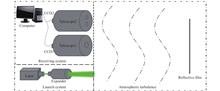
ObjectiveAffected by atmospheric turbulence, the laser produces scintillation, beam wander, and fluctuation of the angle-of-arrival. Beam wander causes the beam to deviate from the target detector and reduces the efficiency of energy transmission, affecting applications such as laser tracking, laser positioning, and optical communications, especially over long distances. Under weak fluctuation conditions, the traditional theory of laser atmospheric propagation can be relatively accurately described. There is still a lack of reliable experimental evidence as to whether the theory is accurate in several kilometers of propagation under deep turbulence near the ground. Most of the current theories and simulations are based on existing assumptions, and there is often a certain deviation from the actual situation, especially under deep turbulence, where the theory is not yet perfect. The distances of the beam wander experiments are all relatively short and do not support the theory associated with long distance propagation. Therefore, it is of great significance to summarize the relevant theories of beam wander under deep turbulence and carry out long-distance laser propagation experiments to reveal the differences between the theoretical model and the reality. The relevant data provide an experimental basis for evaluating the model accuracy or error, and optimizing or correcting the model.MethodsFirstly, the theory of the variance of the drift angle for different refractive index power spectral models in the moderately to strongly turbulent region is summarized and derived. Then, the experiment system of fold path laser propagation (Fig.1) was built to collect the echo spot data using a large-aperture telescope and the atmospheric coherence length by an atmospheric coherence length meter. Four days of experiments were carried out on the 1 km propagation path and three days on a 7 km propagation path. The daily variation of the standard deviation of drift angle is obtained by calculating the echo spot data and studied in comparison with the theory. Simultaneously, the variation of turbulence anisotropy during the experiment period is analyzed.Results and Discussions On the 1 km and 7 km propagation paths, the daily variations of the standard deviation of drift angle and the atmospheric coherence length show some periodicity, with synchronized changes but opposite trends (Fig.2). The standard deviation of drift angle decreases with increasing atmospheric coherence length, showing good agreement with the theoretical variation curve (Fig.3). The Rytov variance is used to classify the turbulence into three turbulence states of weak, medium and strong. Thereinto, the 1 km propagation path passes through three turbulence states, and the degree of proximity to the different theoretical models varies in different states (Tab.2). The relative deviation of turbulence in different states is further analyzed. On the 1 km propagation path, the measured values are closest to the theory based on the Von Karman refractive index model, with an average relative deviation of about 18.20%. While on the 7 km propagation path, the theory based on the modified Rytov shows a good agreement with the measured values, with an average relative deviation of about 21.09%. On the 1 km and 7 km propagation path, the anisotropy factor $R$ of the laser beam wander gradually converges to 1 as atmospheric coherence length decreases (Fig.6), which means the beam wander tends to be isotropic. The anisotropy factor can reflect the contribution of thermal convection and transverse wind to the turbulent energy injection, and its specific influence mechanism needs to be further explored. The appropriate model and method of simulation needs to be chosen according to the specific situation, which will help to improve the accuracy and reliability.ConclusionsIn this paper, the experimental system of laser fold path propagation is decomposed into laser propagation and spot image propagation, and formulas for the variance of the drift angle under moderate to deep turbulence are summarized and derived. The measured values in the 1 km propagation path are closer to the theoretical values based on the Von Karman refractive index model, and the average value of the relative deviation over four days is 18.2%. The measured values on the 7 km propagation path are closer to the theoretical values based on the modified Rytov theoretical refractive index model, and the average value of the relative deviation over three days is 21.09%. The anisotropy factor $R$ of the laser beam wander tends to 1 as ${r~~0}$ decreases, which means the beam wander tends to be isotropic. Through this experiment, we have a clearer understanding of the laser echo beam wander characteristics under different propagation conditions, the range of the standard deviation of drift angle intervals and their deviation from the theoretical expectations, which is of great significance for the model selection and engineering application evaluation. The relevant data have a certain reference value for revealing the target-in-loop laser propagation mechanism under deep turbulence conditions, and provide indispensable experimental data for optoelectronic systems involving laser aiming, positioning, coupling, and other applications.
May. 25, 2024Vol. 53 Issue 5 20230719 (2024)
Qiuwei Xia, Zhen Zhang, Saifen Yu, Haiyun Xia, and Fanfeng Pan
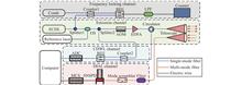
ObjectiveThe chemical industry occupies an important position in the national economy. However, it is also facing challenges such as environmental pollution, carbon dioxide emission, resource consumption and safety risks. Therefore, it is particularly important to develop remote sensing technology that can monitor pollutant discharge, dangerous gas leakage, wind and rain and other meteorological elements in chemical parks with high sensitivity, high stability, wide range and continuous day and night monitoring. In recent years, 1.5 μm lidar has been regarded as an important detection means for the detection of atmospheric environment and atmospheric parameters due to its advantages of human eye safety, continuous day and night observation, high spatial and temporal resolution, all-fiber integration, low power consumption and high stability. At present, differential absorption lidar (DIAL) has been used to detect the concentration distribution and flux emission of various greenhouse gases and dangerous gases, while coherent wind lidar (CDWL) is also widely used to detect atmospheric multiple parameters such as wind field, aerosol and precipitation. Lidar has gradually become one of the important means of safety and environmental protection monitoring in chemical parks. For this purpose, atmospheric multi-parameter detection lidar is applied in the field of safety and environmental protection in chemical industry park.MethodsFor simultaneous detection of aerosols, gases, and wind fields, we built an atmospheric multi-parameter lidar system integrating direct detection module and coherent detection module (Fig.1 and Tab.1). The outgoing light source uses a tunable external cavity semiconductor laser (ECDL) as the detection light source (On wavelength laser) and a fiber laser as the reference light source (Off wavelength laser). the ECDL's outgoing frequency is locked by the optical frequency comb. The receiving system consists of two parts: direct detection module and coherent detection module. In direct detection module, the signal is detected by a large area superconducting nanowire single photon detector (SNSPD). Gas detection requires high sensitivity, and SNSPD provides a higher signal-to-noise ratio than coherent detection techniques. In coherent detection module, the backscattered signal is coupled with the local oscillator light and detected by a balanced detector. In this system, direct detection module uses differential absorption technology of molecular spectrum for gas detection, and coherent detection module uses range correction echo signal, doppler frequency shift, turbulent kinetic energy dissipation rate (TKEDR), the velocity gradient of wind profiles and power spectrum deep analysis technology for pollutant, wind, rain, turbulence and wind shear.Results and DiscussionsFirstly, by combining the detection results of range correction echo signal PR2 and wind vector, the atmospheric multi-parameter lidar can be used for the early warning and monitoring of pollutant emission tracing and diffusion. The stability of monitoring and the accuracy of tracing are verified by experiments (Fig.2-3). Then, the accuracy and stability of carbon dioxide monitoring by the atmospheric multi-parameter lidar were verified through long-term and large-scale monitoring experiments on CO2 distribution in chemical industry park (Fig.4-6). Finally, in view of the simultaneous detection of wind and rain by CDWL, the atmospheric multi-parameter lidar is applied to the fine meteorological support of the chemical industry park, and the meteorological observation capability of the atmospheric multi-parameter lidar is verified by observation experiments. (Fig.7).Conclusion and Prospect A set of atmospheric multi-parameter lidar integrated with direct detection and coherent detection is applied to the safety and environmental protection of chemical parks. In general, the atmospheric multi-parameter lidar has a good application prospect in the field of safety and environmental protection in the chemical industry park, which can accurately and stably achieve tracing of pollutant emissions, monitoring gases, and refined meteorological support. The application of atmospheric multi-parameter lidar in chemical industry park can effectively improve the level of environmental protection and optimize the ability of safety management, and realize the sustainable development of chemical industry park. Due to the use of scanning light sources, it is theoretically possible to achieve the detection of a variety of gases. (Tab.2) In the future, we will use atmospheric multi-parameter lidar to detect a variety of dangerous gases in the chemical park, and plan to integrate polarization detection capabilities on atmospheric multi-parameter lidar to enhance pollutant and gas classification capabilities.
May. 25, 2024Vol. 53 Issue 5 20240068 (2024)
Xuezhu Lin, Tingxuan Wang, Lili Guo, and Lijuan Li
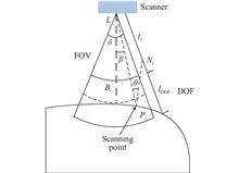
ObjectiveIn the fields of mold manufacturing, automobile assembly and aviation manufacturing, 3D measurement is an important link to verify whether the product shape accuracy meets the design specifications. With the continuous development of technology, manual measurement has been unable to meet the needs of modern production applications. Therefore, automatic measurement technology with higher detection accuracy and measurement efficiency has gradually come to the fore. However, the current automatic measurement method has the problem of lack of data in complex structure areas when dealing with characteristic regions with complex curvature changes, so it is difficult to be directly applied to the scanning measurement of large and complex surfaces. The methods to solve these problems are usually lack of universality, and the path planning method needs to be selected manually, which leads to low scanning efficiency. Therefore, it is necessary to design an efficient automatic measurement method for this kind of complex surface. For this reason, through extensive research, this paper proposes a feature adaptive automatic scanning path planning method based on the scanner's own scanning constraints (Fig.4).MethodsFirst of all, on the basis of constructing the scanning constraint conditions of the laser scanner, this paper analyzes its influence on the scanning accuracy (Fig.3). Secondly, aiming at the problem of scanner attitude planning, a new measurement inclination constrained clustering algorithm is proposed to cluster the sampling points obtained from discrete complex surfaces to realize scanner attitude planning (Fig.10). On this basis, the scanning path points are obtained (Fig.13). Thirdly, aiming at the scanning path planning problem, the approximate algorithm is improved by introducing the normal vector angle matrix as the penalty matrix, and the scanning path planning that meets the requirements is realized (Fig.15). Finally, taking the car door as the scanning object, the measurement process is as follows: first, according to the measurement task planning, the automatic measurement system enters the preset task station. Several measuring target points are installed on the car door, the relative position and pose of the car door and the flexible measurement system are determined by using the laser tracker, and the standing position of the system is fine-tuned to meet the accuracy requirements of pose estimation. Then the scanning path is generated by the feature adaptive scanning method designed in this paper. The scanning path data is converted to the robot flange coordinate system based on the system coordinate transfer model, and the task instructions that can be executed by the measuring system are obtained. Finally, based on the analysis and processing of the scanning data, the measurement results are obtained, that is, the single complete measurement of the object to be tested is realized (Fig.17).Results and DiscussionsThe effectiveness of the proposed method is verified by building a flexible measurement system, in which the manipulator is an Erbidi LT1500-C-6 universal robot, its workspace is a spherical area within the range of 1 500 mm around the base joint, the payload 10 kg, and the repeated positioning accuracy is ±0.05 mm. The scanning equipment is Hexcom's Leica T-Scan5 line laser scanner, which uses the Leica laser tracker AT-960M to track and position the scanner. The execution module is decoupled from the measurement module to ensure that the accuracy of the measurement data is not affected by the cumulative error of execution (Fig.16). The experiments are compared with the traditional line-cut scanning method and manual scanning method from the four dimensions of scanning efficiency, scanning accuracy, scanner attitude transformation times and scanning integrity. The experimental results show that compared with the line-cut scanning method, the attitude transformation times of the scanner are reduced by 54% (Tab.4), the measurement accuracy is improved by 64.5% (Tab.6), and the scanning integrity is close to that of the manual scanning method (Tab.2). Automatic scanning measurement for complex surfaces can be realized.ConclusionsA feature adaptive path planning method for automatic measurement of large and complex surfaces is proposed, and the automatic acquisition of 3D measurement data of large surfaces is realized. The attitude of the scanner is planned based on the scanning constraints of the scanner itself, and the scanning trajectory and scanning posture are optimized, which improves the execution efficiency and universality of path planning. Meanwhile, it can maintain good scanning integrity for the areas with complex curvature changes on the measured surface. The proposed method is tested in the design scene, and the traditional automatic measurement method and manual measurement method are compared with the traditional automatic measurement method and manual measurement method from the four dimensions of scanning efficiency, scanning accuracy, scanner attitude transformation times and scanning integrity. The results show that the scanning efficiency of the proposed method is higher than that of manual scanning, and the scanning accuracy and scanning integrity are improved. The number of attitude changes in the scanning process is much less than that of the line-cutting method, and it can replace manual automation to complete the scanning measurement of complex surfaces.
May. 25, 2024Vol. 53 Issue 5 20240009 (2024)
Fangchao Zhai, Qinghua Zeng, Yuejie Zhang, Helong Wang, and Jie Li
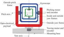
ObjectiveThe optoelectronic stabilization platform is an important component of airborne optoelectronic systems, which plays a role in target tracking and imaging, isolating external disturbances of the carrier, and improving imaging quality. The optoelectronic stabilization platform is an important combat equipment for flight carriers such as helicopters, reconnaissance aircraft, and unmanned aerial vehicles. It plays an important role in the entire combat chain tasks such as search, detection, locking, tracking, strike, and evaluation. With the continuous improvement of battlefield demand, the accuracy requirements of optoelectronic stabilization platforms have gradually increased from tens of microradians to within ten microradians. The optimization of optoelectronic stabilization platform control algorithms is the most direct and cost-effective method to improve its stability accuracy. The current control algorithm for optoelectronic stabilization platforms mainly relies on PID algorithm, and in algorithm design and control, model free or ideal zero free models are used. However, in actual systems, there are often zero points, and the dynamic zero points that are not considered seriously limit the further improvement of system stability accuracy. Therefore, this paper proposes a disturbance rejection control design method for optoelectronic stabilization platforms that considers the zero point of the transfer function.MethodsThis paper proposes a disturbance rejection control design method for optoelectronic stabilization platforms that considers the zero point of the transfer function. In the analysis of the system model, the flexible transmission between the motor and the load was taken into account (Fig.2), and the model of the photoelectric stable platform with zero point was derived (Eq.2). By perturbing the platform model with zeros (Eq.12), the system with zeros is transformed into a system with disturbances but without zeros (Eq.18). Furthermore, through disturbance estimation and compensation, the system model is ultimately transformed into a standard model (Eq.25). Finally, the system controller was designed using zero pole cancellation method to achieve high-performance closed-loop control of the optoelectronic stable platform.Results and DiscussionsThe disturbance rejection control of the optoelectronic stable platform considering the transmission zero point can achieve high-performance command response and disturbance suppression through disturbance design, disturbance estimation, and disturbance compensation, while considering the dynamic conditions of the system zero point. A simulation verification experiment was designed for this algorithm (Fig.5), and the corresponding performance of the system's instructions was evaluated by adjusting indicators such as setting time, rise time, and overshoot (Fig.6). The results showed that the proposed algorithm reduced the setting time by 37.2% and overshoot by 62.35% compared to the traditional PID algorithm. Compared with MLADRC, the overshoot increased by 80.72% and the setting time increased by 61.97% while ensuring the same rise time (Tab.1). The disturbance suppression ability of the system was verified through the method of equivalent disturbance injection, which is superior to traditional methods such as PID and MLADRC (Fig.7). Finally, through physical experiments, it was verified that the disturbance suppression capability within 5 Hz was improved by more than 80% compared to traditional PID controllers, and the disturbance capability was improved by 27.41% compared to MLADRC (Tab.3). This algorithm has excellent disturbance suppression ability.ConclusionsA disturbance rejection control algorithm for optoelectronic stabilization platform considering transfer function zeros has been designed. This algorithm has the characteristics of considering the dynamics of model zeros, excellent instruction response, and strong disturbance suppression ability. It can convert system models containing zeros into zero free systems for controller design. Simulation and physical verification experiments show that the algorithm has significantly improved performance in step command response and disturbance suppression within 5 Hz compared to traditional PID control algorithm, linear active disturbance rejector control design algorithm, and model assisted linear active disturbance rejector control design algorithm, which can effectively enhance the performance of the optoelectronic stability platform system.
May. 25, 2024Vol. 53 Issue 5 20240030 (2024)
Yang Zhang, Junhong He, Yanzhao Ke, Yidong Guo, Junrui Liang, Xiaoya Ma, Jun Ye, Jiangming Xu, Jinyong Leng, and Pu Zhou
ObjectiveWith the rapid increase of the output power of fiber lasers, the stimulated Raman scattering effect in optical fibers has also attracted more and more attention. On the one hand, it is one of the main limiting factors for the further increase in the power of current high-power fiber lasers. On the other hand, it can be used as a new way for laser generation, which is expected to achieve both high-power and wide-band laser output. Current Raman fiber lasers are mainly based on low-loss quartz fibers. In order to optimize the performance of a Raman fiber laser, the researchers doped the quartz fiber with different elements to change its Raman response characteristics. For example, the Raman gain coefficient of optical fibers can be increased by doping germanium, and the Raman peak with a frequency shift of about 40 THz can be introduced by doping phosphorus elements to achieve wavelength conversion with a large frequency shift. Different doping components and doping concentrations will change the Raman gain spectrum of the fiber, and the measurement of Raman gain spectrum of the fiber is of great significance for the design of Raman fiber lasers. Currently, the measurement of the Raman gain spectrum of optical fiber is mainly based on the small signal method, which has a long testing time, and the measurable frequency shift range is limited by the wavelength tuning range of the seed laser, so it is difficult to obtain the Raman gain spectrum of the fiber over broad frequency shift range.MethodsTo measure Raman gain spectrum of the fiber over broad frequency shift range, a new method which derive the Raman gain spectrum of optical fiber from its spontaneous Raman scattering spectrum is proposed. Firstly, the backward Raman scattering spectrum is measured by the experimental setup (Fig.7). The pump source is a ytterbium-doped fiber laser operating at 1018.4 nm. Two bandpass filters are spliced after the pump source to remove the background noise. The filtered pump is coupled into the test fiber through a circulator. And the backward Raman scattered light is transported into the optical spectrum analyzer through the P2-P3 passage of the circulator. The backward Raman scattering spectrum of the test fiber can be obtained by subtracting the transmission spectrum of the P2-P3 passage (Fig.2(b)) from the output spectrum from P3 port of the circulator. Secondly, the Raman output powers under different Raman gains is calculated using the power balanced model. From the measured spontaneous Raman scattering spectrum and the calculated Raman output powers at different Raman gain coefficients, the Raman gain spectrum of the test fiber can be obtained.Results and DiscussionsThe simulated Raman output powers at different Raman gain coefficients is shown (Fig.5(b)). The output spectrum from P3 port of the circulator is shown in Fig.8(a). From the data above, the Raman gain spectra of a phosphorus-doped fiber and germanium-doped fiber over a broad frequency shift range of 1-42 THz are obtained. The measured results are shown (Fig.8(b)). To validify the accuracy of this method, the measured Raman gain coefficients are compared to that measured by the traditional small signal amplification method. In the frequency shift range of 1.6-22 THz, the results agree well with the Raman gain data measured by the traditional small signal amplification method.ConclusionsA new method to derive the Raman gain spectrum of optical fiber from the spontaneous Raman scattering spectrum is proposed. Using this method, the continuous Raman gain spectra of a phosphorus-doped fiber and an undoped silicon-based fiber in the range of 1-42 THz are obtained. In the range of 1.6-22 THz, the Raman gain coefficients obtained by this method agrees well with the results of the small signal amplification method. This work provides a convenient and accurate method for measuring the continuous fiber Raman gain spectrum over broad frequency shift range.
May. 25, 2024Vol. 53 Issue 5 20240041 (2024)

Ling Li, Jiafu Zhang, Xin Tao, Zongwei Yu, Mengxu Li, Renyuan Wang, Xi Chen, Chengguang Cui, and Xiangdong Wang
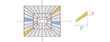
ObjectiveAspherical surfaces are widely used in modern optical systems. With the rapid development of various optical instruments, especially laser ignition devices, laser weapons, and satellite products, which have high standards for cleanliness, smoothness, and other quality aspects, the trend in customized development is quickly shifting towards modularization and batch production. As key components of the optical system, the automation of manufacturing, inspection, and assembly of aspherical surfaces directly determines the quality and efficiency of mass production. The automated optical inspection of aspherical surfaces has also raised increasingly higher requirements. Interferometry, especially compensation methods, is a rapid, precise, and non-contact technique with the potential for automated test of aspheric surfaces. In order to meet the stringent requirements for surface cleanliness of ultra-smooth aspherical surfaces used in high-energy lasers and other fields, and to eliminate the impact of cleanliness and thermal disturbances introduced by inspectors, researchers have developed an automated interferometric detection method for ultra-smooth aspherical surfaces with high cleanliness.MethodsThe mathematical relationship between the amount of misalignment and wavefront aberration is determined by the compensation method based on the theory of vector wavefront aberration. Spherical and defocus aberrations are only affected by the position of the compensator or aspheric surface under test along the optical axis direction. Tilt, coma, astigmatism, field curvature, and distortion aberrations are influenced by the tilt and eccentricity of the optical elements. The order of the effects of tilt and eccentricity on aberrations varies. Based on the analysis, the automated interferometry test method is proposed. By establishing the sensitivity matrix between the misalignment amount of the aspheric surface and the wavefront aberration of the compensated interferometric method, it is possible to utilize the wavefront aberration to calculate the measured misalignment amount of the aspheric surface. The design utilizes the Stewart platform integrated test backplane to achieve the adjustment of the measured aspherical surface in six degrees of freedom. Taking the out-of-focus, coma, and dispersion of the ideal interference system as the optimization objectives, feedback control is implemented to achieve the automated adjustment of the measured aspherical surface. Subsequently, the automated interferometric detection of the high-cleanliness ultra-smooth aspherical surface is achieved.Results and DiscussionsSimulation and experiment utilize the same aspheric surface under test, which is an ellipsoidal surface. The compensation consists of two lenses with plane wave incidence. In the simulation, random misalignment of the aspheric surface is introduced, which includes positional errors along the optical axis, tilt errors, and eccentricity errors. The wavefront aberrations, i.e., Zernike coefficients, can be obtained through simulation. The misalignment is addressed through simulation and continuously adjusted until the misalignment and aberration reach an acceptable level. Simulation initially verifies the feasibility of the automated interferometry test method. In the experiment, the aspheric surface is mounted on the back plane of the Stewart platform using a snap-in interface. The interferogram can be obtained through simple coarse adjustment as the initial state of the experiment. The experimental results show that within the measurable range of the interferogram, the convergence of the aspherical surface misalignment can be achieved through a few iterative steps using the sensitivity matrix. Combined with Stewart's six-degree-of-freedom adjusting stage, the system enables translation error adjustment with a precision of 2 μm and automated optical axis alignment with a precision of 2". Finally, the precision adjustment of the measured aspherical surface is completed, achieving automated interferometric detection of the high-cleanliness ultra-smooth aspherical surface.ConclusionsThe automated interference detection method for aspherical surfaces utilizes a sensitivity matrix and adjustments in six degrees of freedom to enable a rapid solution and automatic correction of measured misalignments of aspherical surfaces. This method eliminates the influence of cleanliness and thermal perturbations introduced by inspectors, enhances the detection speed of aspherical surfaces, and achieves automated interference detection of ultra-smooth aspherical surfaces with high precision.
May. 25, 2024Vol. 53 Issue 5 20240059 (2024)
Wenjiang Fu, Zengxiong Lu, Xiaobin Wu, Yufeng Huang, Bin Gao, and Xuetong Chen
ObjectiveThe six-degree-of-freedom displacement measurement technology based on position sensitive detector (PSD) and corner cube retroreflector plays an important role in the precise measurement of the initial position and attitude of the precision displacement stage in a compact space. Decoupling between the displacement of 6 degree of freedom (6DOF) displacement stage and the displacement of light spot on PSD is the key to realize precise measurement. In order to reduce the complexity of establishing and solving the model, the small angle approximation method or first-order Taylor series expansion can be used to transform nonlinear trigonometric function terms into linear terms, but this method is not universal enough to meet the needs of high-precision measurement in large ranges. In order to meet the demand of high-precision measurement under large angle, it is necessary to establish a more accurate theoretical model and solve it.MethodsAiming at the six-degree-of-freedom displacement measurement system, the theoretical model is accurately described by trigonometric function rather than small angle approximation, and the analytical relationship between the six-degree-of-freedom displacement of 6DOF stage and the change of the spot position on PSD is derived, and a more accurate measurement model is established. When solving the model, the numerical calculation method is used to complete the model solution, which affords remarkably higher accuracy than the traditional small angle approximation method. In the model simulation, the calculation errors introduced by numerical calculation method and small angle approximation method under the single-degree-of-freedom displacement of 6DOF stage are compared. For six-degree-of-freedom displacement, Monte Carlo simulation is used to compare the accuracy of numerical calculation method and small angle approximation method.Results and DiscussionsThrough a 6×9 transformation matrix, the relationship between the displacement of 6DOF stage and the change of spot position on the three PSD can be established. Single-degree-of-freedom displacement will introduce calculation errors in all six degrees of freedom. For the translation displacement in the range of ±10 mm, the calculation error introduced by numerical calculation method and small angle approximation method can be ignored. For the rotational displacement in the range of ±10 mrad, the translational displacement errors introduced by the numerical calculation method are all less than 1.48×10⁻¹⁶ mm, and the rotational displacement errors are all less than 1.73×10⁻¹⁵ mrad, the maximum error is far less than the sub-micron accuracy requirements of the system. But the maximum error of the translational displacement calculation introduced by the small angle approximation method is 5.39 μm, which does not meet the sub-micron accuracy (Tab.2). For six-degree-of-freedom displacement, the translation displacement errors and rotation displacement errors obtained by the numerical method are less than 1.6×10⁻¹⁴ mm and 1.1×10⁻¹³ mrad, respectively, and the maximum error is much less than the accuracy requirement of the submicron level of the system. The accuracy of the numerical method depends on the number of iterations set by the computer and the error introduced by the computer in floating-point operation. However, the maximum error of translational displacement obtained by small angle approximation method is about 5.3 μm, which can not ensure the measurement accuracy of submicron level (Fig.6). Therefore, although the small angle approximation method is simple, its accuracy is much lower than that of the numerical method. Because the small angle approximation method provides iterative initial values for the numerical calculation method, the numerical calculation method has natural advantages in solving the displacement of six degrees of freedom. By using the numerical method, the number of iterations can be artificially set and the accuracy of the algorithm can be improved.ConclusionsAiming at the six-degree-of-freedom displacement measurement system, a more accurate measurement model is established. The numerical calculation method has high accuracy, and the maximum error is far less than the sub-micron accuracy requirement of the system. The decoupling method in this paper is of great significance to the high-precision displacement measurement of 6DOF displacement stage with large rotational displacement.
May. 25, 2024Vol. 53 Issue 5 20240061 (2024)
Haiyong Zhu, Zhijiang Zeng, Wen Sun, Zhenli Zhao, Guangyu Fan, Peng Ji, Qi Zhang, Fulong Zhuang, and Xue Li
ObjectiveInfrared detection technology finds applications in various fields such as medical detection, meteorological detection, space remote sensing, national defense, and military. It converts infrared radiation signals into electrical signals and offers advantages like strong anti-interference capabilities and a wide detector range. In comparison to traditional detection technology, infrared detection technology is better equipped to handle complex and ever-changing environments. The advancement of space infrared detection technology has led to increased demands for infrared detection performance. As a result, large-area array and long-line array infrared detectors have emerged as the future direction of infrared detector development. This article focuses on the research of 2 k×2 k detectors, analyzing the characteristics and challenges associated with packaging technology for large-area array detectors. It also proposes corresponding solutions and methods.MethodsThe suppression of the infrared system's own radiation is crucial for ensuring the imaging quality of the optical system. This study analyzes the impact of the self-radiation of key surfaces in the Dewar component on the stray light of the detector. To reduce the stray light of the large-area array detector, low-temperature optics are employed in the design of the Dewar window (Fig.2). The study also examines the effect of Dewar window deformation on the imaging quality of the optical system under three different working conditions (Fig.4). Additionally, the research investigates the impact of the cold platform's structural design on noise suppression in detection, and evaluates the influence of the transition substrate thickness on the fluctuation of the detector's operating temperature (Fig.5, Tab.3). In contrast to commonly used wires like gold wire, silicon-aluminum wire, and platinum wire, this study introduces the use of platinum-iridium wire with high strength and low thermal conductivity in aerospace-grade packaging design for the first time (Fig.8). The components were evaluated for aerospace mechanics.Results and DiscussionsAmong the various components of the Dewar, the radiation from the Dewar window has a significant impact on the stray light of the 2 k×2 k detector. The stray light emitted by the 300 K Dewar window accounts for approximately 29.9% of the detector signal illumination (Fig.2). However, by implementing a low-temperature optical design with a 200 K Dewar window, the stray light emitted by the window is reduced to only 5.9% of the detector signal illumination. To minimize window deformation, the window cap is appropriately thickened. Fortunately, the impact of window cap deformation on the imaging quality of the optical system can be disregarded under all three working conditions (Tab.2-3). In order to mitigate the noise caused by mechanical disturbances from the refrigerator, a 5 cm thick layer of SiC substrate is added between the detector and the cold head. This effectively eliminates noticeable noise disturbances in the central area of the detector (Fig.5), resulting in a detector operating temperature fluctuation of less than 0.1 K (Tab.4). Furthermore, the use of platinum-iridium wire as component bonding wire improves both the conduction heat leakage and lead strength of the Dewar. The maximum conduction heat leakage is reduced from 576 mW to 49 mW, leading to a corresponding decrease in refrigerator power consumption from 72 W to 39 W. Additionally, the lead pull force experiment shows a value greater than 0.245 N, indicating satisfactory lead strength. The encapsulated components have successfully passed aerospace-grade mechanical tests (Fig.9).ConclusionsThis article aims to address challenges in the packaging technology of large-area array 2 k×2 k infrared detector components. The study focuses on various aspects including the low-deformation window support structure, low-noise cold platform structure, low heat leakage, and high-reliability wire bonding process. The research successfully resolves issues related to stray light, deformation of large-diameter windows, and detection in large area array detector packaging. By tackling problems such as detector noise, lead heat leakage, and strength, the study achieves an outstanding performance in the assembly of a large area array 2 k×2 k infrared detector.
May. 25, 2024Vol. 53 Issue 5 20230634 (2024)
Shuang Wu, Jianyi Zhang, Honglei Chen, and Ruijun Ding
ObjectiveHigh dynamic range (HDR) is an important requirement of the advanced Infrared Focal Plane Array (IRFPA). It is limited by the small electric charge capacity and noise of readout integrated circuit (ROIC). One of the common strategies to expand electric charge capacity is well capacity adjusting based on selectable integration capacitors. The other method is multiple sampling implemented by analog-digital converter (ADC) in conjunction with time delay and integration (TDI) technique. However, capacitors and ADC occupies large area, and TDI causes low frame frequency. Correlated double sampling (CDS) is commonly used to reduce low-frequency noise and KTC noise. Nevertheless, the fold effect of CDS due to large-signal saturation, which leads to wrong readout of large-signal, lacks analysis and elimination. Therefore, it is necessary to propose a new structure to enhance the charge capacity in small pixel area and incorporate CDS guaranteed large-signal readout. For this purpose, an adaptive-gain ROIC (AGROIC) integrated with anti-fold CDS (AFCDS) is designed in this paper.MethodsThe AGROIC and AFCDS is constructed in this paper. AGROIC is accomplished by CTIA in parallel with a MOSFET Mag whose gate voltage is adjustable (Fig.2). The small-signal is integrated through a large-gain CTIA with small capacitor, while the large-signal is injected through the MOSFET, which convert CTIA to RTIA. The conversion gain of ROIC is transformed from the ratio of time to integral capacitance to the reciprocal of the transconductance (Fig.3). The CDS fold effect is caused by saturation of input signal (Fig.7). A fully-passive CDS connected with a MOSFET switch Maf is combined with AGROIC to suppress noise of small-signal (Fig.8). In contrast, the switch turns on in response to large-signal resulting in direct injection to the sampling capacitance (Fig.9).Results and DiscussionsThe proposed AGROIC and AFCDS are integrated in 15 µm pixel pitch, designed in 180 nm 3.3 V CMOS process. The simulation results demonstrate the aforementioned analysis (Fig.4, Fig.11). A 640×512 FPA ROIC is designed and fabricated, which consists of AGROIC-AFCDS input stage, control register, time sequence generator, column buffer, multiple outputs, etc. (Fig.12-13). The tests of the designed system are based on an IRFPA testing platform combined with signal generation, clock generation, voltage source, LABVIEW software and signal acquisition (Fig.15). The noise electrons are significantly decreased to 17 e- because of the CDS in pixel (Fig.17). The conversion relationship between injection current and output voltage extremely decreases when the input signal is large enough to turn on Mag, which increases the charge handle capacitance to 1.6 Me- under finite output swing (Fig.18). Therefore, the dynamic range of this circuit is improved to 99.66 dB. Besides, the testing results present the fold effect on condition of turning off Maf and improper gate-voltage setting (Fig.19). The appropriate setting can eliminate the CDS fold effect.ConclusionsA 640×512, 15 µm pixel pitch ROIC incorporated with adaptive-gain ROIC and anti-fold CDS is designed and implemented. A new approach to realize gain adaptation is proposed as follows. The ROIC automatically converts from high-gain CTIA to low-gain RTIA depending on the magnitude of the signal, which ensures high sensitivity readout of small-signals and expands the detection range. The design is suitable for complex small-signal application, such as hyperspectral imaging applications with weak radiation and large differences between elements. The design requires small integration capacitance and can be applied to smaller pixel area. Besides, the fold phenomenon of CDS under large signal is analyzed, and a concise solution is proposed. The designed AGROIC-AFCDS eliminates the fold effect of CDS, suppress the noise to 17 e-, expands the maximum detectable charge to 1.63 Me-, and improves the dynamic range to 99.66 dB. It is a new method to realize HDR in small pixel area which can adapt to the advanced infrared focal plane technology.
May. 25, 2024Vol. 53 Issue 5 20230688 (2024)
Yangmei Liu, Yuezhang Hou, Ting Luo, Yuanzhu Zhou, Yuqi Sun, Zhili Li, Tianshu Wang, and Xinjian Pan
ObjectiveUltrafast mode-locked fiber lasers have gained increasing popularity in various fields due to their narrow pulse width, broad spectrum, and high peak power. In the field of laser medicine, for instance, ultrafast lasers have emerged as a novel treatment method for combating cancer and treating stones. The integration of ultrafast lasers and time-frequency technology in the field of optical frequency comb measurement has yielded remarkable advances, such as the development of optical atomic clocks, microwave photonics, and other emerging technologies. Furthermore, the optical frequency comb has the potential to be implemented in space missions. Ultrafast mode-locked fiber lasers are being used more and more widely and have high application value. Mode-locked technology is the main way to generate ultra-short pulses. Currently, among the main mode-locked methods, mode-locked laser based on the nonlinear amplifying loop mirror has the characteristics of fast response time, high damage threshold, high environmental stability, low phase noise and short output pulse, which is considered to be the most promising ultrafast laser for large-scale application. Unfortunately, this kind of laser often requires external disturbance or high pump energy when it is started, which greatly reduces the reliability of the laser and increases the application cost. In order to improve the reliability of mode-locked laser in practical applications, femtosecond fiber lasers based on Jones matrix are reported.MethodsIn this paper, a mode-locked laser based on a non-reciprocal phase shift for a nonlinear amplifying loop mirror is set up (Fig.1). The non-reciprocal phase shifter consists of a Faraday rotator, a half waveplate, a λ/8 waveplate, and a mirror. By rotating the angle of the waveplates, the laser takes into account the characteristics of self-starting and wide spectrum, and the gratings are inserted into the cavity to balance the positive dispersion and outside of the cavity to compress pulses. The transfer function of nonlinear amplification loop mirror is established by using Jones matrix to analyze self-starting performance of the mode-locked fiber laser (Fig.9). The influence of different wave plate angles in loop mirror on the roundtrip transmission of the cavity is analyzed (Fig.2).Results and DiscussionsThe fiber lasers are demonstrated by using Yb-doped fiber and Er-doped fiber as gain media respectively. Gratings (1 000 lines/mm) are used in the Yb-doped fiber laser to balance the positive dispersion. The fundamental frequency with repetition rate of 600 MHz (Fig.3) and 280 MHz (Fig.5) is observed by an oscilloscope. The designed lasers have the characteristics of narrow pulse width (Fig.4, Fig.6), good stability (Fig.7) and high self-starting success rate. The laser has been integrated and packaged, which can meet the application requirements of femtosecond laser in micro-nano processing, laser medical treatment, optical frequency comb and other fields.ConclusionsA nonlinear amplifying loop mirror femtosecond laser is designed, which achieved repetition rates of 600 MHz and 280 MHz at wavelengths of 1 µm and 1.5 µm, respectively. At a pump power of 960 mW, the ytterbium-doped fiber laser output an average power of 180 mW and a pulse width of 249 fs. The erbium-doped fiber laser output a power of 104.7 mW, with a direct output pulse width of 109 fs and a compressed pulse width of 60 fs. The spectrum had a flat top and supported output pulses in the hundreds of femtosecond range, which could effectively reduce thermal accumulation during laser processing and improve processing efficiency. This laser structure achieved high integration with an easy-to-dismantle package, a broad spectrum, and supported self-starting mode-locking, multiple output channels, and stable operation, making it a suitable seed source for future femtosecond laser products.
May. 25, 2024Vol. 53 Issue 5 20230703 (2024)
Rui Wang, Dongliang Zhang, Chengcheng Zhang, Qinghua Lin, Mingxin Luo, Xiantong Zheng, and Lianqing Zhu
ObjectiveQuantum cascade laser (QCL) in the mid-infrared (MIR) band suffer from the problem of limited output power, and many important applications require high power outputs above the watt level and high beam quality. Simply increasing the width of the active region can obtain higher power output, but it often directly affects the beam quality and generates a large amount of heat in the core region that cannot be exported, resulting in the device not being able to operate continuously. If a set of narrow-ridge QCL phase-locked arrays, can greatly improve the thermal efficiency, but also avoid the different phases between the units QCL brought about by the problem of poor beam quality, to facilitate the realization of high-power continuous output.MethodsThe seed laser is designed with a resonator composed of a 50% Bragg mirror on the front and a 100% Bragg mirror on the back. A stable laser beam with a central wavelength of 4.6 μm is achieved; a thermal simulation analysis was established to determine the array distance at the amplified end; in order to avoid the problem of poor beam quality caused by phase inconsistency between the laser array elements, the 1×16 beam splitter consisting of a multimode interference coupler (MMI) and a bend waveguide is designed, so that the seed optical passing through the beam splitter can maintain the phase consistency and realize the function of uniform beam splitting; Al2O3 anti-reflection coating is plated on the array output port, and optical amplification is completed through the end amplification part to achieve coherent beam enhancement of laser output power.Results and DiscussionsThe simulation results show that the reflectivity of the total and semi-reflector mirrors is 100% and 50% for the beam with a central wavelength of 4.6 μm, indicating that optical with a wavelength of 4.6 μm can be used to generate stable oscillations using the mirrors (Fig.8). The total transmittance of the 1×2 MMI output port with the taper is 99.8%, and the optical field distribution is clear and stable, indicating that uniform beam splitting with low loss is achieved (Fig.9 and Fig.10). Due to the high symmetry of the beam splitter, each beam passes through waveguides of equal length, resulting in consistent phase at the amplification end. A comparison is made between different amplifier array spacings in terms of temperature and far-field distribution (Fig.11 and Fig.14). The output port of the array is coated with Al2O3 coating, and its high transmittance can further increase the output power of the laser (Fig.13).ConclusionsAiming at the low output power of the current single QCL, a QCL phase-locked array with an operating wavelength of 4.6 μm is designed to improve the output power of the laser. The epitaxial thickness of each layer of the device is determined by mode analysis, combining the calculation of optical limiting factor and waveguide transmission loss, and the single-mode waveguide is designed. The waveguide loss is 0.055dB·cm-1, and the optical limiting factor is 0.733. A seed laser with a laser wavelength of 4.6 μm is designed by using a resonator composed of 100% and 50% Bragg mirrors. The 1×16 low loss splitter is designed by using MMI and bending waveguide, and its loss is 0.254 dB. The output port is plated with 0.7 μm thick Al2O3 anti-reflection coating, and the transmission rate can reach 0.975, which further improves the output power of the laser.
May. 25, 2024Vol. 53 Issue 5 20240014 (2024)
Chengcheng Zhang, Dongliang Zhang, Rui Wang, Mingxin Luo, Qinghua Lin, Xiantong Zheng, Lianqing Zhu, and Weiping Wang
ObjectiveQuantum cascade laser has the advantages of unipolarity and easy wavelength adjustment, which has become an important laser source for mid-wave infrared. To satisfy the demand for pulsed high-power quantum cascade lasers, wide-ridge waveguide technology is often used to obtain ultra-high pulse peak power, which will cause the transverse heat dissipation path of the active layer to become longer, make the heat accumulation of the core layer more serious, and reduce the performance of the device. In addition, increasing the ridge width leads to an increase in the number of intrinsic modes supported in the waveguide, which lases higher-order modes and eventually degrades the beam quality. Therefore, in this article, a longer cavity length and a narrower ridge structure are designed to significantly enhance the fundamental mode and increase the heat dissipation capacity simultaneously. Additionally, a long tapered structure is incorporated on the output surface to elevate the optical loss threshold. To a certain extent, high beam quality propagation is guaranteed and the optical power density of the device is reduced. It has important research significance.MethodsA new tapered waveguide structure model is established by COMSOL simulation software. The optical and thermal characteristics of a tapered high-power quantum cascade laser are simulated with an output of 60 W and a pulse frequency of 10 kHz in pulse mode. The optical field mode distribution under different ridge widths (Fig.3) and the influence of different geometric parameters on the port transmittance, the optical limiting factor of the waveguide (Fig.5-7), and the heat dissipation effect are mainly analyzed. The impact of different heat sink materials, varying heat sink temperatures (Fig.8), and diverse pulse widths (Fig.9) on the core region temperature of the fixed device structure under identical pulse mode is investigated.Results and DiscussionsIn the waveguide optical field mode analysis, for 4.6 μm wavelength, when the waveguide width is less than 5.6 μm, the luminescence mode of QCL laser is TM fundamental mode, and the higher order mode is restrained (Fig.4). In the analysis of output port characteristics, for 3 mm or longer cavity length, the waveguide loss is kept at a low level of 0.17 dB/cm, and the core area of the tapered waveguide laser is about 10 times larger than that of the strip ridge waveguide structure, which is more conducive to high-power output (Fig.7). In the heat dissipation analysis, when copper heat sink is used and the total cavity length is 4 mm, the entire core layer has a lower maximum internal temperature and a faster heat dissipation rate (Fig.9).ConclusionsThe optical and thermal structures for the pulsed high-power quantum cascade laser which incorporates a novel tapered waveguide design are modeled and simulated by using COMSOL optical finite element simulation software. The impact of various geometric parameters on the mode distribution and transmission characteristics of waveguides is analyzed. In conclusion, at a wavelength of 4.6 μm, the ridge waveguide width is 5 μm, the taper Angle is 1.9°, and the ridge/taper length ratio is 1:3, which can ensure that the ridge waveguide will produce TM fundamental mode output, and the transmission, reflectivity, loss, and light limiting factor of the entire port can achieve the best effect. In addition, the structure is subjected to thermal simulation analysis under various pulse modes, which provides a useful reference for the selection of device operating mode and packaging mode. The relevant conclusions of this study can provide data support for the subsequent process design and experimental verification.
May. 25, 2024Vol. 53 Issue 5 20240015 (2024)
Dawei Liu, Guang Yang, Daijun Luo, Jiashaner Dana·, Guangyu Fan, and Yi Liu
ObjectiveThe advancement in ultrafast optics has propelled research on light-matter interactions into extreme optical conditions characterized by strong fields and high energies. However, many innovations and applications demand specialized laser parameters, including wavelength, intensity, pulse duration, and repetition rate. Particularly, wavelength is a crucial yet less flexible parameter to control. This paper reports the Serrodyne nonlinear broadening and frequency conversion induced by the molecular alignment effect in ultrafast pulses, achieving precise wavelength shifting. By investigating the relationship between pulse shape and transient frequency, we elucidate the mechanism of the Serrodyne effect in triggering nonlinear dynamical processes. Unlike Kerr nonlinearity, in the molecular alignment system, the magnitude of spectral shift is influenced by both the molecular response time and pulse width, providing possibilities for introducing new degrees of freedom in the control of ultrafast light sources.MethodsIn our study, we employ numerical simulations to introduce the Serrodyne effect into the Kerr system and achieve molecular alignment through the nonlinear Schrödinger propagation equation. Our objective is to establish the relationship between the shape and direction of the sawtooth pulse and the spectral frequency shift of the pulse. The nonlinear propagation dynamical induced by the Serrodyne effect are elucidated by mapping the transient frequency in relation to the pulse shape in the time domain. To comprehensively explore this effect, we adopt two approaches. Firstly, we maintain the steepness of the sawtooth-shaped pulse constant while adjusting the pulse width by varying t1 and t2 in equal proportions. This approach enables a systematic investigation into the effect of pulse width with a fixed shape pulse. Secondly, we vary the steepness of the pulse by adjusting the ratio of t1 and t2, denoted as Ri (Ri = t2/t1), allowing us to explore the impact of changes in steepness.Results and DiscussionsFigure 1 reveals that the spectrum exhibits symmetrical redshift and blueshift as the direction of the sawtooth pulse changes. For Kerr nonlinearity, a more substantial shift is achieved by generating steeper sawtooth pulses, as depicted in Fig.1(a) and Fig.1(b) with Ri set at 3. A clear observation from Fig.2(a) and 2(b) reveal the symmetrical nature of the Kerr shift when the direction of the sawtooth pulses is reversed. Results obtained at Ri of 10, depicted in 2(c) and 2(d), show that when the ratio of Ri increases, there is no significant alteration in the nature of the frequency shift, only a reduction in the shift range. To gain a deeper understanding of Kerr's symmetrical frequency shift, the pulse shape is plotted against the transient frequency in Fig.3(a)-3(d). A comparison indicates that as the steepness decreases (i.e., the pulse width increases), there is minimal difference in the overlap of pulse energy with the transient frequency, maintaining the fundamental nature of the frequency shift. Figure 5-6 illustrate the frequency shift of molecular alignment with different sawtooth waveforms. In contrast to the Kerr effect, molecular alignment exhibits two significant differences. Firstly, when sawtooth pulses with the same degree of steepness and opposite directions are applied, the shifted results show asymmetry. Secondly, varying degrees of steepness in sawtooth pulses result in different properties of shifted frequency.ConclusionsIn this study, we explore two distinct nonlinear effects arising from the introduction of sawtooth pulses generated by the Serrodyne effect based on both the Kerr nonlinearity and the molecular alignment nonlinearity. Comparative analysis reveals that the molecular alignment system exhibits more complex and nuanced nonlinear processes than the regular periodic Kerr nonlinearity. Within the molecular alignment regime, the transient frequency's magnitude is influenced by the molecular response time and pulse duration, introducing novel degrees of freedom for nonlinear frequency shifting of spectra. Our study provides a new perspective on our understanding of nonlinear effects in molecular alignment, thereby deepening our knowledge of designing ultrafast light sources. At the practical application level, precise tuning of parameters, such as the steepness and direction of the sawtooth pulse, enables directional control of the nonlinear Serrodyne effects. Optimizing these pulse parameters facilitates precise manipulation of nonlinear effects to induce frequency shifts, thereby opening up new possibilities for enhancing the performance and innovative applications of ultrafast light sources. Such new light source, applicable in strong field physics, precision spectroscopy, optical communication, and imaging, offers a large bandwidth, tunability, efficiency, and compactness, along with flexible and diverse regulatory mechanisms.
May. 25, 2024Vol. 53 Issue 5 20240046 (2024)
Quan Zhou, Xinqiang Zhao, Hui Kong, Jintian Bian, Haiping Xu, Han Shu, Jierui Zou, and Yuntao Xie
The 900 nm laser based on a KTiOPO4 (KTP) optical parametric oscillator (OPO) was demonstrated for the first time. The 532 nm laser was produced from a LiB3O5(LBO) pumped by 1064 nm laser. The wavelength tuning range of 898-911 nm, tuning resolution better than 1 nm, output energy of 1.85 mJ, and repetition rate of 1-10 Hz was obtained, which can be applied to optoelectronic countermeasures for its solidification, miniaturization, wide tuning, high tuning resolution, and high beam quality.Objective The spectral response of a 900 nm wavelength laser on a silicon detector is better than that of 1064 nm, and it is located at the transition absorption line of atoms, ions, etc. It can also generate blue light laser with frequency doubling. Therefore, it can be widely applied in fields such as optoelectronic guidance, atmospheric detection, and deep-sea communication. Currently, semiconductor lasers commonly used to generate 900 nm wavelength bands have a low tuning range and are difficult to output high-energy pulses. The optical system of titanium sapphire laser is relatively complex, and it is difficult to achieve miniaturization and lightweight, and the tuning speed is slow. Nd3+ doped solid-state lasers are difficult to achieve wavelength tuning output and are prone to energy level competition. We need a suitable crystal and technology to solve the above problems and achieve better optical performance of 900 nm laser output. Optical Parametric Oscillator(OPO) can convert mature 1064 nm laser into ultraviolet, visible, near-infrared, mid to far infrared laser bands, and has advantages such as solid-state design, miniaturization, high efficiency, high beam quality, and wide tunable output wavelength. The use of high damage threshold KTiOPO4(KTP) and OPO can achieve high conversion efficiency, wide tuning range, and high tuning resolution of 900 nm laser output.Method A tunable 900 nm wavelength laser based on KTP OPO has been built (Fig.2). We chose LBO frequency doubling crystal to double the 1064 nm laser output from Nd: YAG laser to 532 nm and use it as the pump light for KTP OPO. The angle of the KTP crystal changes with the adjustment knob above, and the output wavelength of the laser can be tuned. The light at the output end is collected by the optical fiber and guided into the spectrometer for spectral analysis. By turning the knob on the upper adjustment bracket, a 900 nm laser within a certain tuning range is successfully captured.Results and Discussions The tuning range of the laser is measured, and a tuning range from 898 nm to 911 nm is achieved (Fig.4). Angle tuning resolution $ \Delta {\lambda }~~{i}/\Delta \theta $=9.56 nm/(°), slightly different from the theoretical result of 10.26 nm/(°). Possible reason is the cutting angle φ of KTP crystals not in the 0° position. The repetition rates of Nd: YAG lasers are set to 1, 2, 5, and 10 Hz, respectively, and the energy of the frequency doubling laser at 532 nmand the energy of the output idler light at 900 nm are measured (Fig.5). When the repetition rates are 1, 2, 5, and 10 Hz, the slope efficiencies are 43.62%, 38.14%, 36.35%, and 31.78%, respectively. The maximum measured output energy is 1845 μJ, 1656 μJ, 1571 μJ, 1397 μJ, respectively. The corresponding light to light conversion efficiencies are 37.81%, 33.93%, 32.19%, and 28.63%. The energy conversion efficiency decreases with the increase of repetition frequency. The possible reason is that the thermal effect caused by the high pulse repetition rate consumes some energy. The pump threshold is maintained at 402-570 μJ under four different repetition rates, remaining basically unchanged.Conclusion A wide tunable and high-precision 900 nm laser output based on KTP OPO has been successfully achieved. The tuning resolution reaches 9.56 nm/(°). The energy output of idler light reaches 1.85 mJ, when the pump energy is 4.88 mJ. The energy conversion efficiency under different repetition rates is also comprehensively measured. The tuning range of the laser system was analyzed by a spectral analyzer, and the measured tuning range spanned from 898 nm to 911 nm. The tunable output of 900 nm laser based on KTP OPO has been proven to be a simple, wide tunable range, high tuning accuracy, and fast tuning speed method.
May. 25, 2024Vol. 53 Issue 5 20240060 (2024)
Qi Chao, Yandong Zhao, and Shengbo Liu
ObjectiveIn the field of computer vision, cameras and LiDAR have their own advantages. Cameras have dense perception and RGB information, which can capture rich semantic information. LiDAR has more accurate ranging and can provide more accurate spatial information. How to utilize the advantages of cameras and LiDAR to achieve information complementarity is the key to improving 3D target recognition. The single-mode laser point cloud recognition network framework, whether based on point or voxel processing methods, cannot effectively solve the information loss caused by long time consumption or point cloud voxelization. Existing multi-modal networks that fuse images overly rely on point cloud input but fail to reduce the information loss caused by point cloud voxelization, weakening the high-dimensional semantic information provided by images and failing to fully utilize the complementary information between point clouds and images. To address the above issues, this paper improves the feature generation network and multi-modal fusion strategy, while proposing a point level multimodal data augmentation strategy to further enhance model performance.MethodsThe multi-modal network framework uses independent image and point cloud branches to extract multi-scale features and fuse them at the feature layer (Fig.1). The image branch uses a depth estimation fusion network to fuse dense perceptual image semantic information and truth supervised deep features (Fig.2), compensating for the disorder and sparsity of point clouds. In the point cloud branch, the feature extraction method for voxelization of point clouds has been improved (Fig.3), no longer solely using voxel center point features, but using vector features, standard deviation features, and extremum features for fusion. By using the dynamic feature fusion module (Fig.4) for feature fusion, the network's ability to extract key features is improved, and global features are obtained more effectively. A point level multimodal fusion data augmentation strategy is proposed, which not only enhances sample diversity but also alleviates the problem of sample imbalance to a certain extent, effectively improving the performance of the model.Results and DiscussionsExperiments are conducted using the open-source publicly available dataset Pandaset for autonomous driving at the L5 level, and IoU is used as an evaluation metric for semantic segmentation performance. We first visualized the point level multimodal fusion data augmentation strategy proposed in this paper on Pandaset, and found that this data augmentation strategy outperforms previous methods in terms of visual effects and sample authenticity in task expansion (Fig.5-6). At the same time, comparative experiments were conducted on this dataset with some mainstream 3D semantic segmentation algorithms based on point cloud single modal processing and image point cloud fusion multimodal processing. The algorithm proposed in this paper achieved performance improvement on most labels and mIoU (Tab.1), and the improvement was more significant on distant or small targets. This fully demonstrates the effectiveness of the algorithm proposed in this article, and verifies the effectiveness of each module proposed in this paper on model performance through ablation experiments (Tab.2). And additional comparative experiments were conducted on the improvement of model performance by data augmentation strategies, which proved that the click data augmentation strategy proposed in this paper is also superior to previous data augmentation methods in object detection tasks (Tab.3).ConclusionsThis paper improves the image and point cloud feature extraction network and designs a multimodal network framework for image and point cloud fusion, combining the advantages of dense perception images and real 3D perception point clouds to achieve information complementarity. A multimodal fusion network framework has been implemented to improve the performance of 3D object recognition, with the performance improvement being more significant on small samples and small targets. This paper demonstrates the effectiveness of the proposed algorithm through comparative experiments and ablation experiments on the open-source dataset Pandaset.
May. 25, 2024Vol. 53 Issue 5 20240026 (2024)
Junfeng Cao, Qinghai Ding, Depeng Zou, Hengjia Qin, and Haibo Luo
ObjectiveThe limited resolution of infrared devices, constrained by cost and manufacturing technology, remains a challenge. While deep learning-based single image super-resolution (SISR) has shown promise in enhancing image resolution, its application in real-world infrared images is hindered by the complexity of actual degradation, including spatial non-uniform blur caused by optical aberration and assembly error, as well as variations in the blur kernel due to environmental temperature changes. A deep learning-based approach for infrared imaging degradation model identification and super-resolution reconstruction is proposed to tackle these challenges. This method entails solving the degradation model using a convolutional neural network to describe the evolution of blur kernels, along with a super-resolution reconstruction method that adheres to the constraints of the degradation model and incorporates online learning of degradation parameters.MethodsImages of calibration targets are captured using an infrared camera placed in a high and low temperature chamber, along with a portable target simulator placed outside it (Fig.1-2). These images are utilized to calibrate the blur kernels. A convolutional neural network (CNN) is employed to construct a model that characterizes the relationship between blur kernel, pixel coordinate, and operating temperature (Fig.3). The model is trained using the calibrated blur kernels. Additionally, a super-resolution network is developed and trained (Fig.4). The operating temperature is initially estimated using the low-resolution image. Next, the initial blur kernels are estimated by inputting the operating temperature into the kernel model. Subsequently, super-resolution reconstruction is conducted based on the estimated blur kernels, and the reconstructed image is utilized to refine the operating temperature and blur kernel estimation. Iterative processes improve the accuracy of blur kernel estimation, leading to enhanced reconstruction outcomes.Results and DiscussionsThe blur kernels of the infrared imaging system exhibit significant variation in response to temperature changes and spatial locations (Fig.6). The trained blur kernel model effectively predicts blur kernels using temperature and pixel coordinate inputs (Fig.7). The average PSNR between predicted and actual blur kernels across different operational temperatures is consistently high, with a minimum of 32.2 dB and an average of 37.1 dB, indicating precise predictions (Fig.8). The calibration and modeling of blur kernels provide valuable prior information for super-resolution reconstruction, resulting in enhanced reconstruction outcomes. Consequently, the proposed algorithm produces visually appealing results with improved detail (Fig.10-11) and enhances objective quality evaluation metrics such as the natural image quality evaluator (NIQE), perception-based image quality evaluator (PIQE), and blind/referenceless image spatial quality evaluator (BRISQUE) (Tab.1).ConclusionsA novel approach is proposed for infrared super-resolution imaging, including degradation model identification and iterative super-resolution reconstruction. The degradation model is based on a convolutional neural network and is solved using offline calibration data. It can predict blur kernels across various temperatures and spatial positions, reducing the need for extensive calibration work. Online degradation parameter correction is achieved through an iterative optimization network alternating between estimating the blur kernel and reconstructing the super-resolution image. By leveraging the degradation model, the complex high-dimensional blur kernel estimation problem is simplified into a low-dimensional operating temperature estimation problem, streamlining the solution process. Through iterations, the accuracy of blur kernel estimation improves, leading to superior super-resolution reconstruction outcomes. Experimental results demonstrate that calibrating and modeling blur kernels enhance prior information for super-resolution reconstruction, yielding superior results. Additionally, the proposed method adapts to a wider temperature range, reducing the stringency of athermalization design requirements for infrared optical systems.
May. 25, 2024Vol. 53 Issue 5 20240049 (2024)
Yinhui Zhang, Kai Ji, Zifen He, and Guangchen Chen
ObjectiveInfrared imaging technology can realize target monitoring and redundant information filtering in complex road scenes by capturing the thermal radiation characteristics of the target for imaging. In order to solve the problems of large number of parameters, dependence on high-performance GPU resources and slow detection speed of infrared pedestrian and vehicle target detection models, an attention-guided multi-scale infrared pedestrian vehicle real-time detection model was proposed which aims to strike a balance between detection accuracy and real-time performance in infrared vehicle and pedestrian target detection tasks.MethodsThis article improves upon the YOLOv5 algorithm and proposes a attention-guided multi-scale infrared real-time detection model for pedestrian and vehicle-IRDet (Fig.1). Firstly, in order to accurately match and calibrate the target scale of infrared pedestrians and vehicles and the size of the anchor frame, this paper uses the K-Means++ algorithm to generate the preset parameters of the preset parameters of the infrared pedestrian and vehicle target scale, and designs a 128×128 fine-scale detection layer. Additionally, the attention-guided global feature extraction module (Fig.3) is designed to enhance the model feature extraction ability and spatial and channel information focusing ability. Secondly, A cross-space perception module (Fig.4) is constructed to introduce spatial information perception to strengthen the feature expression ability of targets in different scales. Finally, the model was made lightweight by using channel pruning (Fig.5-6) to reduce model parameters.Results and DiscussionsIn order to avoid overfitting caused by the similarity between adjacent frames in model training, this article conducts sparse filtering on the FLIR Thermal Starter assisted driving infrared dataset, removing images with high similarity. In order to evaluate the performance of the algorithm in this paper in multiple aspects, the evaluation criteria for the model are Average Precision (AP), mean Average Precision (mAP), Model Size (Size), Single Image Reasoning Time (Time), Floating-point Arithmetic (Flops) and Model Parameters (Parameters). The ablation experiment (Tab.2) shows that the average detection accuracy of the improved infrared pedestrian and vehicle detection model has increased from 83.1% to 88%. However, this also leads to a significant increase in model size, thus requiring compression of the model. The scaling factor comparison experiment (Tab.3) identifies the optimal scaling factor.The pruning experiment (Tab.4) shows that while ensuring the accuracy and speed of the model, the optimal pruning rate is determined to be 0.8. Comparative experiments (Tab.5) have shown that our model exhibits the best detection performance when compared with other models.ConclusionsThis article proposes a lightweight infrared pedestrian and vehicle detection algorithm, which combines fine-scale detection layers and uses K-Means++ algorithm to recluster prior boxes suitable for infrared pedestrian and vehicle, which helps the model locate targets more accurately. Attention-guided global feature extraction module was proposed to enhance the model feature extraction ability and spatial and channel information focusing ability. The dynamic detection head is embedded into the original detection head to improve the model's detection ability. A cross-spatial perception module was designed to correlate the spatial feature information of infrared images at different scales. Based on the improved pedestrian and vehicle detection model, a BN layer channel pruning strategy was used to compress and fine tune the model, achieving deep compression while maintaining accuracy.
May. 25, 2024Vol. 53 Issue 5 20240063 (2024)
Qingge Li, Xiaogang Yang, Ruitao Lu, Jiwei Fan, Bin Tang, Zhenyu Zhang, Siyu Wang, and Shuang Su
ObjectiveIn complex environments where satellite signals are denied, especially at night or under low-light conditions, infrared remote sensing images can provide richer and more reliable visual information, which is the key to realizing autonomous visual positioning of aircraft at night. When there is a large angle rotation between infrared images, it will lead to matching localization failure. For this reason, this research proposes a rotation matching localization method based on hierarchical reinforcement. This research not only improves the accuracy and efficiency of matching localization, but also expands the application scope of autonomous visual localization technology for aircraft, which has an important impact on promoting the development of key technologies for aircraft navigation and guidance, situational awareness and autonomous decision-making.MethodsThe research describes a hierarchy-enhanced feature point rotation matching localization method (Fig.2). First, the RBN-SuperPoint deep feature point extraction model with residual connection encoder was designed to detect and describe the feature points of the input images (Fig.3). Secondly, L-LightGlue is utilized for coarse matching of feature points to obtain the homography transformation matrix (Fig.6). The L-LightGlue adopts linear attention for feature aggregation, which solves the problem of weight decay or explosion that may be caused by dot-product attention when dealing with long-distance dependency, and the computational complexity is lower and more efficient (Fig.7). Combined with the designed hierarchical structure-enhanced rotation matching strategy, L-LightGlue exact matching is performed after eliminating the rotation angle differences between images, and the corrected feature point matching results and the corresponding homography transformation matrix are obtained. Finally, the position mapping of the center points in the image is calculated using last obtained homography transformation matrix to obtain the aircraft localization results.Results and DiscussionsThe feature point extraction experiments show that the RBN-SuperPoint algorithm extracts a larger number of feature points, whether under light changes, viewpoint conversion, scale changes or other complex scenes, and can identify and extract key feature points more efficiently, with stronger feature extraction capability. Matching performance comparison experiments show that the L-LightGlue algorithm combined with the hierarchical structure rotation strategy is able to match more feature points, with a matching accuracy of up to 98.57%, an average matching accuracy of 97.99%, and an average matching error as low as 1.07 pixel, which ensures the accuracy of the matching while maintaining a faster matching speed. The experimental results of aircraft localization show that the localization method combining RBN-SuperPoint feature point extraction and L-LightGlue matching algorithm outperforms other algorithms in terms of localization accuracy, and the average localization error is 4.08 pixels, which verifies the validity and reliability of the proposed localization method.ConclusionsThe study introduces a matching localization method based on hierarchical feature point rotation matching, integrating deep feature point extraction and multi-level rotation matching localization techniques to enhance the accuracy and robustness of aircraft matching localization. Initially, the RBN-SuperPoint model is employed for precise detection and description of deep feature points in images, followed by the L-LightGlue adaptive matching algorithm for efficient feature point matching, establishing accurate inter-image transformation relationships. A hierarchy-enhanced rotational matching strategy is utilized to effectively eliminate matching errors due to angular differences between images, and achieve more precise image matching localization. Experimental evidence confirms the effectiveness of the method, with RBN-SuperPoint enhancing feature point extraction efficiency and uniformity, and L-LightGlue achieving a matching accuracy of up to 98.57% and a minimum average matching error as low as 1.07 pixels. This rotational matching localization method records an average localization error of merely 4.08 pixels, significantly improving aircraft navigation guidance and situational awareness in complex environments. Demonstrating promising results in infrared imaging modes, the potential application of this method across various imaging modes, including satellite remote sensing, multispectral, and synthetic aperture radar (SAR) images, is identified for future exploration. This exploration aims to enhance the accuracy and applicability of cross-modal matching localization and further advance the development of autonomous aircraft technology.
May. 25, 2024Vol. 53 Issue 5 20240086 (2024)
Yunpeng Wang, Jing Yan, and Xiang Hao
SignificanceFluorescence microscopy stands as one of the most potent tools for probing cellular structures and dynamic processes. Recent advances in super-resolution imaging techniques have surpassed traditional diffraction limits, achieving nanometer-scale resolution in live biological samples. However, the complex variation in refractive indices within biological specimens often reduces imaging performance due to aberrations induced by the sample itself. AO, a technology designed to correct wavefront errors, when integrated into super-resolution microscopy, can significantly enhance the imaging resolution, depth, and speed of super-resolution systems. In pursuit of further augmented imaging performance in super-resolution microscopy, researchers continually innovate applications of AO within the realm of super-resolution techniques. It is foreseeable that AO will experience rapid development in the field of super-resolution microscopy, substantially enhancing the imaging capabilities of super-resolution systems. This underscores the significant importance of research into AO within the context of super-resolution microscopy.ProgressInitially, the application of AO in fluorescence microscopy and its classical methodologies are presented; This is followed by a categorization and summation of AO's applications in super-resolution microscopic imaging in recent years. Aberration measurement is broadly categorized into two approaches of direct wavefront sensing and indirect wavefront sensing. In direct wavefront sensing, Wavefront Sensors (WFS) are commonly employed to directly measure phase aberrations in the received wavefront. Notably, the Shack-Hartmann Wavefront Sensor (SH-WFS), due to its compact size, low cost, simplicity, and ease of operation, is frequently utilized. Indirect wavefront sensing calculates aberrations indirectly via the intensity distribution of images produced by the microscope. One method of this indirect measurement utilizes phase retrieval, reconstructing the pupil function by imaging fluorescent beads and extracting aberrations from it; Another relies on image quality metrics, imposing aberration biases on each mode and determining correction parameters by maximizing image quality measures such as brightness, contrast, sharpness, and resolution. The widespread application of AO in microscopy has significantly improved the imaging performance of microscopic systems, greatly aiding in the detection and correction of aberrations within fluorescence microscopy. Subsequently, a brief introduction is provided on the types and principles of super-resolution microscopy. The spatial resolution of traditional optical microscopes is limited by the diffraction limit, whereas super-resolution microscopy elevates the resolution by an order of magnitude. The three principal types of super-resolution microscopy are Single-Molecule Localization Microscopy (SMLM), Structured Illumination Microscopy (SIM), and Stimulated Emission Depletion Microscopy (STED). SMLM achieves nanometric precision in positioning by utilizing the signal sparsity of activated fluorescent markers, temporally separating microscopic structures that are spatially challenging to divide. SIM, a wide-field technique, uses high-frequency structured illumination to transpose the spatial frequency of the sample into the passband of the microscope's diffraction limit. STED, a point-scanning method, employs point spread function engineering to generate a “doughnut-shaped” hollow focus spot to deplete the fluorescence groups, causing stimulated emission depletion and producing an effective sub-diffraction volume of fluorescent excitation. Finally, the application of AO across various super-resolution microscopic imaging techniques is discussed, addressing the imaging characteristics and underlying optical principles of each method. The conclusion synthesizes the trajectory of super-resolution microscopy's development with the latest advancements in AO technological innovation, providing a prospective summary.Conclusions and ProspectsOriginating in astronomy and later flourishing in the realm of microscopic imaging, AO technology has become an indispensable component of super-resolution microscopy due to its formidable capacity to correct wavefront aberrations. Higher spatial resolution, greater imaging depth, additional imaging dimensions, and faster imaging speeds represent the perpetual goals of scholars in the super-resolution field. The author aims to provide a reference for the integration of AO technology with the super-resolution microscopy domain by detailing the application of AO in super-resolution microscopic imaging, with the expectation that the use of AO technology will become even more widespread and profound in the field.
May. 25, 2024Vol. 53 Issue 5 20240011 (2024)
Chao Liu, Rong Wang, Bin Lan, Xueying Li, Kaihe Zhang, Tianjun Dai, and You Zhang
Significance The random fluctuations of atmosphere cause turbulence effects, such as beam distortion, expansion, drift, and scintillation. Turbulence poses a serious problem for beam propagation in space, limiting the use of optical systems. Atmospheric turbulence suppression has become a problem that must be solved in technical fields such as astronomical imaging, laser atmospheric transmission, and space-atmosphere laser communication. Generally, the main suppression methods mainly include adaptive optics technology, signal processing technology, and non-diffracting beam transmission technology, which have problems such as complex systems or unsatisfactory effects. Finding a simple, effective, stabilizing transmission technique that allows the beam to suppress turbulence is important for scientific research.Progress In recent years, a special beam called optical pin beam has been proposed and used to suppress atmospheric turbulence, which has received widespread attention in the academic community. The optical pin beam, which belongs to a special type of non-diffracting beam, is synthesized from multiple radially symmetric Airy beams. It has the characteristic of self-focusing during transmission. Before reaching the focal point, the transverse wave vectors cancel each other out, and the spot at the focal point is minimized. After passing through the focal point, it degenerates into a Bessel-like beam and continues to propagate forward. Compared to ordinary beams, optical pin beams have more concentrated beam energy and smaller spot energy when transmitted through turbulent environments. With the depth study of the optical pin beam, in order to adapt to various complex application environments, its derived pin-like optical vortex beams and steady optical beams have also been found to have extremely high research value. After turbulence transmission of the same intensity, the pin-like optical vortex beam has improved its center of mass shift and jitter by more than 50% compared to the LG vortex beam. The beam parameter product of the steady optical beam within a transmission distance range of 20 mm is only 49.40% of that of the Gaussian beam. The optical pin beam has been proven to suppress atmospheric turbulence effectively and achieve stable long-distance transmission. The use of optical pin beams for atmospheric transmission has a simple system structure, low cost, and high real-time suppression of turbulence with good results.Conclusions and Prospects The optical pin beam can resist turbulence transmission and exhibits self-focusing transmission properties in turbulent environments, which are more stable than those of Gaussian beams, and the spot energy is more concentrated than that of conventional Gaussian beams. Its excellent properties are expected to play a more important role in turbulence suppression studies. Its derived beams such as pin-like optical vortex beams and steady optical beams also show better performance in anti-turbulence transmission, and are expected to be applied more in fields such as laser communication and imaging. In scenarios where complex adaptive optics systems cannot be applied, the use of optical pin beams for correction of aberrant wavefront is a great turbulence suppression technique. Therefore, it is of great theoretical and practical application value to carry out research on the transmission characteristics of optical pin beams and their derived beams, and their applications in the fields of laser atmospheric transmission and atmospheric laser communication.
May. 25, 2024Vol. 53 Issue 5 20240098 (2024)
Chenchen Fan, Min Fu, Xiulu Hao, Shanmin Huang, Yang Li, Zilun Chen, Jinyong Leng, Tianfu Yao, and Pu Zhou
ObjectiveRaman fiber lasers are distinguished by their exceptional capabilities in generating high-power lasers at specific wavelengths, attracting considerable interest and research efforts. In recent years, the utilization of graded-index multimode fibers in Raman lasers has not only increased the injectable pump power but also enhanced laser brightness through beam cleaning characteristics. Currently, significant breakthroughs have been made in Raman fiber lasers based on large-core graded-index multimode fibers, with researchers successfully achieving kilowatt-level near-single-mode output.MethodsAn all-fiber Raman laser system was built based on the oscillator structure. Extensive design optimization of passive fiber components, including fiber refractive index, core diameter, mode field area, as well as combiners and fiber gratings, was conducted to effectively suppress higher-order Raman effects and prevent degradation of beam quality. The system utilized multiple 1080 nm lasers as the pump source, which were combined by a custom-designed fiber combiner. The Raman gain medium was a piece of graded-index fiber with a length of 18 m and a core diameter of 150 μm. The resonator cavity was constructed using a pair of specially designed fiber gratings with mode-selecting characteristics, featuring a central reflection wavelength of 1130 nm.Results and DiscussionsThe power evolution of the laser system, illustrated in Fig.1(a), demonstrated that with pump power injection of 2392 W, the signal laser output reached 1780W with residual pump power of 340 W, corresponding to a Raman conversion efficiency of 74.4%. Figures 1(b) and (c) indicated that as the power increased, a discernible broadening of the output spectrum and degradation in beam quality were observed, attributed to heightened nonlinear effects. Specifically, as the signal power increased from 200 W to 1780 W, the 3 dB linewidth of the output spectrum widened from 0.7nm to 1.9 nm, and the output beam quality factor M² degraded from 2.5 to 3.5 (average values derived from multiple measurements). Moreover, at the maximum power level, the intensity of 2nd order Raman laser is 40 dB lower than that of signal laser.ConclusionsAn all-fiber Raman oscillator with output of 1.8 kW was successfully achieved, setting a new public record for the highest reported power to date. Through the optimization of fiber and passive components, it is expected that higher-power Raman fiber lasers can be realized in the future.
May. 25, 2024Vol. 53 Issue 5 20240031 (2024)
Tianying Chang, Xing Chen, Miao Yu, and Hongliang Cui
ObjectiveThe primary technical objective of the present work is to combine real data in terms of a subway tunnel structural health (including its concrete structure and the surrounding soil and rock support and burial) at strategic locations along a segment of the tunnel obtained by fiber optic sensors of strain and displacement, and simulations based on finite element continuous mechanics, and to assess the sensor effectiveness as well as its deployment locations. Iteration of this process leads to an optimal sensor system for the effective and efficient monitoring of the subway tunnel under both static and dynamic operating conditions. A structural health monitoring project of geotechnical application is carried out based on the real-life subway segment of the Suzhou Metro Line 4 branch from Hongzhuang Station to Lishu Station, using finite element simulation analysis of the static stress/strain field and dynamic field of tunnel structures under normal operating conditions and deploying optical fiber sensor network.MethodsSimulation and modeling are carried out using standard finite element analysis of continuous mechanics; Experiments are conducted using a system of fiber optic sensors, including strain gauges, displacement sensors. The data output of the sensors over an extended period of time is used to analyze the structural health of the tunnel, and the simulation/modelling is compared with the sensor data, which also serves to guide the placement of the sensors. According to the simulation results and on-site investigation results, a fiber optic sensing network which can monitor real-time information such as horizontal displacement, cracks, settlement, structural stress, surface strain, and vibration of tunnel structures is designed and deployed successfully. The real-time health status monitoring of tunnel structures is achieved and the reliability of the finite element model is verified, which resulted in a more accurate finite element simulation model. Finally, two-dimensional finite element models are established for three main sections of the subway segment, and the distribution of concrete structural damage under the influence of metro train vibration loads is studied under two conditions: with and without damage to the tunnel structure.Results and DiscussionsThe main results of this study include: 1) Statics analysis points to the fact that the maximum stress of the tunnel is located at the lower part of the tunnel, with a symmetric distribution, and the maximum strain is located at the top of the tunnel. 2) For the dynamics analysis, the resonant frequency and vibration modes were first obtained, based on which the acceleration and velocity distribution were obtained. 3) Using the simulation obtained static and dynamic distribution and actual field observations, fiber Bragg grating displacement sensors, strain sensors, crack sensors, static pressure sensors and distributed fiber optic vibration sensors were place, for long-term, in-situ monitoring of the tunnel structural health. 4) Based on the measurement output of the system of fiber optic sensors, the finite element model is updated and optimized, to reflect the real situation of the tunnel.ConclusionsAs a result of the work reported, better insurance of the safe operation of the subway segment has been achieved, and the model and methods developed here can be readily applied to other subway segments, and more generally other geotechnical structures involving underground tunnels and tracked vehicular traffic. The present study has reported the successful use of a combination of finite element static and dynamic modeling with fiber optic sensor network output, for better insurance of the safe operation of underground subway tunnel. The model and methods developed and demonstrated here can be readily applied to other subway segments, and more generally other geotechnical structures involving underground tunnels carrying tracked vehicular traffic.
May. 25, 2024Vol. 53 Issue 5 20230712 (2024)
Kang Zhang, Haiming Jiang, and Kang Xie
ObjectiveWavelength Division Multiplexing (WDM) is one of the core technologies in fiber optic communication system. In WDM system, a number of optical signals with different wavelengths are transmitted simultaneously in a single optical fiber, realizing the multiplexing of the optical signals, and solving a series of problems in large-capacity, high-speed data transmission. At the receiving end of WDM system, the multiplexed optical signals are demultiplexed into a series of single wavelength optical signals, then further detected and identified to usually obtain the peak values of the signals for the next applications. Generally, the peak value of the target single-wavelength optical should be detected and identified in real time. For this purpose, we designed and developed a real-time peak detection system for multi-wavelength optical signals based on multi-window recognition, which realizes the detection and recognition of the peaks for the multi-wavelength optical signals.MethodsThis work proposes a real-time peak detection system for multi-wavelength optical signals based on multi-window recognition. The optical demultiplexing part uses an Fiber Fabry-Perot Tunable Filter (FFP-TF) to filter out the target single-wavelength signal from the multiple-wavelength optical signals. The driving and controlling circuit of FFP-TF and the low-noise weak optical signal conversing and detecting circuit are designed. The former is used to drive and control the FFP-TF to filter out the optical signals of the target wavelengths and the latter detects and converts the power intensity of the optical signals in real time. The detected optical signal power is converted into voltage intensity. Then the peak position and intensity in the voltage waveform are identified by using a method based on multi-window waveform identification. At last, the corresponding peak intensity and wavelength position of the optical signal waveform is obtained. The system realizes the filtering of the target wavelength optical signal, and the detecting and identifying of the peak intensity in the signal waveform at the target wavelength.Results and DiscussionsFirstly, a standard spectrometer is used to detect the optical signal waveform of the experiment light source. The results are illustrated (Fig.11). Secondly, the detection system proposed and developed in this work is used to determine the same experiment light source. The comparison of the results measured by the standard spectrometer and by the detection system proposed and developed in this work is shown (Fig.12). The corresponding data to Fig.11-12 are shown (Tab.1). It can be seen that the peak points of the signal waveform obtained respectively from the standard spectrometer and the detection system proposed and developed in this work agree very well. The measurement variation of the peak intensity obtained from the detection system is less than 0.01 dBm and the recognition time is less than 3 s. More experiment results illustrated in Fig.13 show that the detection range of the system proposed and developed in this work is 0--60 dBm.ConclusionsIn this work, a real-time peak detection system for multi-wavelength optical signals based on multi-window recognition is proposed and developed. The driving voltage of the FFP-TF is controlled to filter out the target wavelength optical signal and the weak optical signal detection circuit converts the target wavelength optical signal into a normal range of voltage. Then the multi-window waveform peak recognition method is used to identify and record the signal peaks in the waveform. The optical signals of different powers from narrowband light source are tested. The results show that the waveforms of the original optical signal and the detected one by the system is consistent. The measurement variations of peak intensity is less than 0.01 dBm, the recognition speed is less than 3 s, and the minimum detectable power of optical signal is as low as -60 dBm.
May. 25, 2024Vol. 53 Issue 5 20240042 (2024)
Taixi Chen, Jinxin Wang, He Huang, Binzhi Zhang, Xin Li, Minyan Qiu, and Xin Zhang
ObjectiveInfrared optical imaging system has excellent environmental adaptability and has been widely used in the field of optical imaging in recent years. In order to make the structure compact, the intermediate image plane formed by the primary and secondary mirror system often retains a large number of primary spherical differences, and the tolerance requirements are strict and the precision of installation is high. At present, the use of infrared interferometer is not popular in scientific research institutions, the commonly used interferometer is visible wavelength interferometer. As a result, the alignment of this kind of optical system often rely on the traditional alignment method that improves the machining accuracy of the mechanical parts and uses the center deviation measuring instrument to assist the positioning, the alignment accuracy cannot be guaranteed. In order to improve the alignment accuracy of this kind of optical system, it is necessary to discuss the alignment method, so that the high-precision alignment of optical system was realized. In this paper, the optical alignment method of a near-infrared refraction catadioptric system with intermediate image plane imperfect imaging of 150 mm aperture and 450 mm focal length was studied.MethodsBased on the near-infrared catadioptric optical system correcting lens group lens material does not block the visible waveband. In order to improve alignment accuracy, the lens blooming of correcting lens group was specially designed (Fig.2), the purpose of using the visible laser interferometer to detect the wave aberration of the system with high precision is realized. Based on the univariate analysis of the offset sensitivity, the coupling and aberration characteristics of each offset dimension are analyzed (Fig.4-5). Based on this, the optical setup scheme of the secondary mirror and the relay mirror group is proposed. The process of alignment strategy (Fig.6) is developed and the actual alignment experiment is analyzed.Results and DiscussionsExperiments show that the center field view wavefront error (RMS) of optical system reaches 0.104λ, F(-1,0) field view RMS is 0.310λ, and F(+1,0) field view RMS is 0.188λ, F(0,-1) field view RMS is 0.216λ, F(0,-1) field view RMS is 0.176λ (Fig.9). When the center field of view is close to diffraction imaging, the edge field of view has serious asymmetry, which is mainly shown as primary astigmatism asymmetry, resulting in poor image quality of the edge field of view (Tab.2). At this time, adjusting the misalignment of the secondary mirror cannot completely eliminate the asymmetry of the edge field of view, so the position of the secondary mirror and correcting mirror group need to be adjusted after several iterations in the process of alignment. After fine alignment of the entire optical system, the center field view RMS reaches 0.114λ, F(-1,0) field view RMS is 0.109λ, and F(+1,0) field view RMS is 0.103λ, F(0,-1) field view RMS is 0.109λ, F(0,-1) field view RMS is 0.110λ (Fig.10), the RMS value of the full field is close to the design value @632.8 nm, achieving the imaging quality requirementsConclusionsThe optical installation method of the near-infrared refraction and reflection system with non-ideal imaging of the middle image plane is mainly studied. The lens blooming of the near-infrared relay lens group is designed through the laser interferometer application band of 632.8 nm, so that the near-infrared optical system can use the visible laser interferometer for high-precision detection alignment. The alignment of intermediate image plane of imperfect imaging near-infrared catadioptric system was studied. Based on the univariate analysis of offset sensitivity, the coupling characteristics of each offset dimension are analyzed. On this basis, the optical setup scheme of secondary mirror and correcting lens group is proposed. The RMS wavefront errors of each field of view of the optical system after installation and adjustment are roughly the same as the numerical values of the design simulation results, and the direction is the same, both of which meet the requirements of imaging quality. The research results can provide an effective reference for the installation of such near-infrared refraction and reflection optical systems.
May. 25, 2024Vol. 53 Issue 5 20240089 (2024)
© Copyright 2018-2021 | Chinese Laser Press.
All Rights Reserved 沪ICP备15018463号-20