


Reproducing astrophysical magnetized dynamical processes in the laboratory has become possible due to the emergence of platforms able to couple high-power laser-produced plasmas and external magnetic fields[ ), coming from the companion star, falls down onto the WD along an accretion column when the magnetic field is over 1000 T, preventing the formation of an accretion disk around the WD[
 and shock temperature. Therefore, several experimental studies have been initiated to study such objects in the laboratory[
High Power Laser Science and Engineering, Volume. 6, Issue 3, 03000e43(2018)
Experimental platform for the investigation of magnetized-reverse-shock dynamics in the context of POLAR On the Cover

The influence of a strong external magnetic field on the collimation of a high Mach number plasma flow and its collision with a solid obstacle is investigated experimentally and numerically. The laser irradiation ( ) of a multilayer target generates a shock wave that produces a rear side plasma expanding flow. Immersed in a homogeneous 10 T external magnetic field, this plasma flow propagates in vacuum and impacts an obstacle located a few mm from the main target. A reverse shock is then formed with typical velocities of the order of 15–20
  5 km/s. The experimental results are compared with 2D radiative magnetohydrodynamic simulations using the FLASH code. This platform allows investigating the dynamics of reverse shock, mimicking the processes occurring in a cataclysmic variable of polar type.
Keywords
1 Introduction
Similarity criteria between the astrophysical problem under study and the laboratory experiment allow making a bridge between the experiment and the polar system. The huge magnetic field associated with these astrophysical systems ( 1000 T) implies, in the laboratory, an extremely high magnetic field (of the order of 100000 T)[
 (which gives an indication on the diffusivity of the B-field inside the plasma,
  , where
  is the flow velocity,
  is the characteristic length and
  is the electrical conductivity) and the
  parameter (which evaluates the ratio between the ram pressure
  and the magnetic pressure
  ), to compare to the polar case where
  and
and  . In such systems, radiation plays an important role as the cooling parameter is of the order of
  where
where  is defined as the ratio between the radiative cooling time
  and the characteristic hydrodynamic time
  . Finally, to be almost similar, the laser produced plasma should have (i) a magnetic pressure dominant over ram pressure, (ii) B-field frozen in the plasma and (iii) important radiation cooling. Other parameters such as density, temperature, and velocity can be found in Ref. [
Here we present our experimental platform developed to study the dynamics of the reverse shock occurring in polar systems, using the coupling between high energy lasers and external magnetic field. The paper is organized as follows. In Section
Sign up for High Power Laser Science and Engineering TOC Get the latest issue of High Power Laser Science and Engineering delivered right to you!Sign up now
2 Experimental setup
The experiment has been performed on the LULI2000 laser facility at LULI laboratory (Ecole Polytechnique, France). A long pulse ( ), high energy (
 at the wavelength
  ) beam has been used to produce a strong shock wave in a multilayer solid target (referred to as the main target in the following): a layer of 25-
 -thick CH, acting as the ablator, and a layer of 6-
 -thick Sn, acting as an X-ray shield against radiation produced in the corona. The main target is glued onto a 4-mm-diameter holder having a 1-mm-diameter inner hole
  (see Figure
  -diameter focal spot, leading to an on-target intensity of the order of
  . When the shock breaks out from the rear Sn surface, a plasma flow is generated that propagates into vacuum and impacts an obstacle located at a distance ranging from 2 to 3 mm depending on the shot. The obstacle used in this experiment was a 3 mm diameter, 1 mm thick Al plate. We diagnosed the dense (
 ) outgoing plasma by X-ray backlighting. To this end, an X-ray source was produced by irradiating a
  diameter vanadium wire with the Pico2000 laser pulse (80 J,
  10 ps, defocused to
  a
a  diameter focal spot). The backlighter source (wire) was located 3 cm below the main target (see Figure
  60 cm above the target-chamber center, leading to a 20x magnification (see Figure
  is similar to the diameter of the V wire, as expected[
 emission line at an energy of 4.95 keV. However, energetic electrons produced by the short pulse laser emit hard X-ray through bremsstrahlung process (see Section
  ) provided some of the fundamental variables of the plasma flow: (i) a simple shadowgraphy recorded the global shape of the plasma, and (ii) a modified Nomarski interferometer enabled inference of the electron density of the flow in the range
  . Both diagnostics were coupled to gated optical imagers (GOIs) with a 200 ps time frame. We also implemented optical pyrometry (either streaked or gated with GOI) to record the self-emission of the flow at a central wavelength of 450 nm having a 40 nm bandwidth. The streaked self-emission gave us the flow expansion velocity on each shot while the gated self-emission provided (2D) images of the plasma emission of the plasma at a given time. These numerous diagnostics are of prime importance both to determine the dimensionless parameters of the generated plasma (the magnetic Reynolds number, the
  parameter, …) and as a constraint for the 2D MHD simulations.
In our experiment, the plasma flow is immersed in an external magnetic field of 10 T generated by a specially designed coil. The coil is coupled to a pulsed power generator[ and stays constant (less than 2% variation) for a few
  , i.e., a duration much greater than the typical hydrodynamical time scale of the experiment. The magnetic-field maximum was synchronized to optical lasers. The coil, designed and fabricated by HZDR, is composed of two solenoids in a Helmholtz-like configuration. The coil windings remain in air to avoid technical problems such as electric flashovers. The magnet features three bores of
  1 cm diameter: one for the high-power laser beam and two for diagnostic purposes (optical and X-ray). All bores intersect in the middle of the split-pair coil where the plasma flow is generated.
3 Experimental results
This section presents the fundamental experimental parameters inferred from the measurements made by our set of diagnostics described above.
3.1 Plasma and reverse-shock velocity
The optical emission of the plasma at a wavelength of 450 nm, with 40 nm bandwidth, has been recorded and used to determine the experimental rear side plasma flow velocities. As can be seen in Figure  for the first
  from the rear side of the main target, called the flow-launching region in Figure
  of the outflow on the obstacle, i.e., the accreting plasma flow velocity (see Figure
  . Indeed, the collision of the plasma flow onto the obstacle compresses and heats the material giving rise to a bright visible emission associated to the reverse shock. The measured velocities are similar in both cases (with and without the B-field): initial velocity of the outflow
  , the mean velocity before impact being of the order of
  depending on the shot and the reverse-shock velocity
  . These data are used to constrain our 2D radiative MHD simulations.
Figure
As can be seen in Figure
There is an important caveat associated with this analysis. What is actually seen by the self-emission diagnostic is the movement of the plasma that is emitting brightly at  450 nm at a high enough density. Plasma that has cooled or rarefied too much would not be seen. This is unlikely to be an issue for the reverse shock, but might affect the measurements of the flow toward the obstacle. Indeed, one would expect the freely flowing plasma to include faster components at lower density, for reasons discussed in Ref. [
 20 to
20 to  40 ns and
  in Figure
  30 to 50 ns and
  in Figure
3.2 X-ray radiography of the plasma
The X-ray source is produced by irradiating a 25- -diameter, vanadium (V) wire using the Pico2000 laser (80 J,
  10 ps, defocused to
  50-
50- -diameter focal spot). The objective is to obtain a quasi-monochromatic X-ray spectrum with the main contribution coming from the K
 at 4.952 keV. The IP detector, situated at
  60 cm above the target, is covered with a 11.4-
 - thick Ti layer that cuts off X-ray photons in the range 0 to
  2 keV and 5 keV to
  8–9 keV. In order to evaluate the X-ray spectrum incident on the IP, additional step filters (Al and Sn) with different thicknesses have been added. The experimental results show, in analyzing transmission through the step filters, that the spectrum is not monochromatic and that a nonnegligible part of the photons have energy above 10 keV due to the emission of continuous radiation via bremsstrahlung process.
Figure  is defined at the beginning of the laser–matter interaction. The temporal dynamics is obtained by delaying the Pico2000 beam with respect to the main drive laser beam. As one can see, two characteristic shapes are observed. The plasma flow has a bubble-like structure close to the rear side of the main target (see Figures
3.3 Effect of the external magnetic field onto the collimation of the plasma flow
This section is devoted to the analysis of the radial extension of the plasma flow with or without the 10 T external magnetic field. One can see in Figure  in Figure
  . Figure
  1.5 mm from the main target. This is a strong indication that the dynamic of the plasma flow (at
  ) is not affected below 1.5 mm by the magnetic field, the magnetic pressure being too small compared to the plasma pressure. However, in the case without magnetic field, the diameter of the plasma continues to increase, as the plasma propagates further from the rear surface of the target. In the case with the magnetic field, we observe a clear difference: at
  1.6 mm, the radial expansion of the plasma stops, the plasma being focused. Our interpretation, discussed below, is that the gradient in magnetic pressure has become large enough to overcome the gradient in thermal pressure and focus the plasma.
4 Radiative MHD simulation of the experiment
This section presents the comparison between the experimental results and the simulation using the FLASH code[ enabling resolution of the Sn layer of the target. In order to save computational resources, the simulation is 2D axis-symmetric. The laser intensity distribution on target has been initialized with a super Gaussian function of a
  radius to simulate the experiment. The time profile of the laser has a rising time of 200 ps followed by a plateau of 1.3 ns at
  , and a decrease of 100 ps. The laser intensity in the simulation has been reduced to reproduce the mean flow velocity (
 see Figure
  thick CH and a
  thick Sn. The washer has a 1 mm hole diameter.
In this section, we compare experimental results with radiative MHD simulation in order to quantify the importance of (i) magnetic field and (ii) radiation for the reverse-shock dynamics. As indicated previously, the experimental distance between the target and the obstacle varies between 2.4 and 3.1 mm. We have here, chosen for the FLASH simulation, a short distance, i.e., 2.4 mm.
4.1 Effects of the B-field
The magnetic field controls part of the system dynamics. In order to tackle its effect, we compared two simulations using a short target–obstacle distance ( ) with and without B-field. The short distance results in a higher mass flux (
 ) toward the obstacle and thus leading to a denser and more visible reverse shock. However, the B-field has a smaller effect on the dynamics when the target–obstacle distance is small, as the ram pressure (
 ) is higher in the case of a short target–obstacle distance for a constant magnetic pressure
  , i.e., the
  is higher than in the case of a longer target–obstacle distance (see Figure
In Figure  and
and  (see Figure
In conclusion, at late time after the beginning of the interaction (i.e., few tens of nanosecond), the magnetic field has an important effect, even at 10 T B-field, to constrain the radial expansion both of the accreting plasma flow and the reverse shock as can be seen in Figure
4.2 Effects of radiation
Radiation can as well have a strong influence in the dynamics of the accreting plasma flow and of the reverse shock. In order to assess its effect, we performed two 2D MHD simulations with a 10 T B-field: the first one uses the radiation module, the radiation transfer being solved in the multi-group diffusion approximation using 40 radiation groups and the second without the radiation module (see Figure  ) underlining its nonradiative nature. The obstacle is slightly heated up to 0.1–0.3 eV. A small expansion is also observed. However, it is difficult to be quantitative on this particular point as the FLASH code is an Eulerian code. Further numerical and experimental investigations are needed. However, strong differences appear in the reverse-shock region. With radiation on, the temperature, so the ionization state, shows a heating of the matter ahead of the shock front up to
  from the target rear surface (see Figures
The differences observed here, in the longitudinal expansion of the reverse shock, especially in temperature and ionization state could be studied experimentally by our SOP diagnostic.
4.3 Direct comparison between experimental data and simulations
This section is devoted to comparing experimental data with the results of the 2D MHD simulation to interpret in details, the fundamental processes involved in the accretion processes and reverse-shock generation.
An X-ray radiography postprocessing of the 2D FLASH simulation has been developed to allow a direct comparison with the experimental data (see Figures  (
( ) and the absorption at each wavelength is
  where
where  is assumed to be constant with temperature and density. This approximation is valid in our plasma conditions.
According to Figures  10 keV) exists that has not been used in the postprocessing process. In order to overcome this issue, we postprocessed the simulation using two different X-ray energies: 4.952 keV and 11.92 keV.
4.3.1 Plasma flow dynamics
As can be seen in Figures  and 0.6 mm in the experiment and
  and
and  in the FLASH simulation for
  ), (ii) an envelope surrounding the plasma flow due to the accumulation of plasma where
  and
and  early in time, as discussed below. This area is located at
  and
and  in the experiment and
  and
and  in the FLASH simulation (see Figure
  14 T in the envelope region at 75 ns and
  13 T at 85 ns. The outflowing plasma forms a reverse shock against the layer of increased magnetic field, so that the accumulating, stagnated plasma creates the zone of increased absorption enhanced in the radiographs by limb-darkening.
Hard X-rays ( 10 keV) increase the signal-to-noise ratio on the X-ray and so decrease the contrast of the X-ray radiography. As a conclusion, one should note that the agreement between the experiment and the simulation is qualitative but not quantitative.
4.3.2 Reverse-shock dynamics
In this section, we discuss the reverse-shock optical emission and X-ray radiography and the FLASH simulation using a 10 T external B-field. Figures  from the obstacle position (
 from the rear side of the main target) agrees well with the peak of the electron and radiation temperatures in the simulation for the two different times. The longitudinal expansion of the emission zone is also well reproduced by the FLASH simulation (it is
  in Figure
Figure  . The longitudinal expansion of the reverse-shock front is in each case close to
  from the obstacle, i.e., at the position where the maximum of the optical emission peak is observed. The length of the reverse shock is better reproduced when radiation is on; however, the difference is not significative enough to conclude.
In conclusion, according to our diagnostics, it is difficult to distinguish whether the reverse shock itself is radiative or radiation changes the nature of the plasma flow. Moreover, a study of the dominant effects due to radiation is necessary. It will give an important input for the understanding of the dynamics of the astrophysical system.
4.4 Effect of the hole diameter on the dynamics of the plasma flow
Understanding the features observed in Figure
The coronal plasma formed on the laser side expands into vacuum, has a high temperature and is able to strongly heat and launch a shock wave in the target holder. As a consequence, a large amount of the material from the holder is ablated and disturbs the dynamics of the plasma for the 1 mm hole diameter (see Figure
The use of a 2 mm hole greatly reduces this effect. It is clearly visible in the experimental data (see Figures
5 Discussion
We can identify three regions in the system under study (see Figure
 (1)
(1) , the density is
  , the magnetic-field vector is
  , and the fluid velocity of the plasma is
  , which we distinguish from the directed speed of the plasma flow,
  . Here one can see that the motion involves a competition between gradients of thermal pressure,
  , and magnetic effects. The two magnetic effects involve the gradient of magnetic pressure,
  , and the magnetic-curvature force. The parameter
  characterizes the competition between thermal and magnetic forces in any region. In studies of accreting flows, the thermal pressure of the shocked plasma at an obstacle is of the order of the ram pressure of the accreting flow,
  . More is firmly known about the incoming flow, than about the shocked plasma at an obstacle, and as a consequence, this has led the community that studies such flows to focus on a ‘ram
  ’, defined as
  . Thus,
  within the shocked plasma at the obstacle. Note that, as
  characterizes the competition between thermal effects and magnetic effects in the shocked matter but not in the accreting flow. Taking the accreting flow to be
  Mach 8, as typical in our experiment, so that the sound speed,
  , is
, is  , we have
  .
.Our diagnostics allowed us to directly infer the propagation velocity, the reverse-shock velocity, the longitudinal and radial extent of the plasma, and the electron density in the range from  to
to  . For reasonable values of ionization (between 1 and 5), this corresponds to a mass density ranging from
  to more than
  . This lets us evaluate the range of
  that is present in the experiment. Figure
  for the 10 T magnetic field of the experiment, and Figure
  for the 20 T B-field of future perspectives. One finds
  for densities below
  for the 10 T case and below
  for the 20 T case. This implies that the magnetic field should not be dynamically important for the accreted plasma flow at early time (
 ), the collimation time being of the order of
  8–10 ns. However, when the density of the leading edge of the accreting flow is small enough, the B-field will constrain its radial extension. Even then, increasing the field to 20 T would reduce the time it takes for the B-field to have an influence on the collimation of the accreting plasma flow. However, for the accreting flow
  so one can infer from Figure
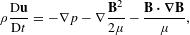
The second relevant equation for the system of interest is the magnetic induction equation,
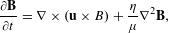 (2)
(2) . (Note that in SI mks units
  is in
is in  and
and  is in Henries/m, which is
  , so that
  has the units of a kinematic diffusion coefficient, as is required.) The two terms on the right-hand side of this equation characterize the competition between convection of magnetic flux by the plasma and the resistive diffusion of magnetic field into the plasma. If the first term is dominant, then any components of
  that are perpendicular to
  displace the magnetic-field lines. If this term was dominant, then the radial expansion of the flow would compress the field surrounding it, increasing
  there. If the second term was dominant, then the field would diffuse through the plasma before any displacement could develop. If we set
  in the first term and
  in the second term, then the ratio of these two terms,
  , is
, is 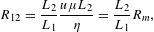 (3)
(3) , with all scale lengths taken to be of order of some reference number
  . For some period of time after the flow emerges from the solid target,
  and the radial expansion of its edges is characterized by
  , for sound speed
  , while in contrast
  is very large (much larger than the plasma diameter), as the field is nearly uniform. This means that
  , where
  is several times of the plasma diameter. During this period, we find that
  is small enough that
  in the flow, enabling the radial expansion of the plasma to push the field aside and compress it. The resulting gradient of magnetic-field pressure resists the plasma expansion. Since the expanding flow is supersonic, a layer of shocked material may form. This would explain the apparent observation of a dense shell near the outer edges of the plasma, as seen in Figure
 Once the gradients approach a common value,  , the field will diffuse a distance
  during the time it takes an acoustic disturbance to cross the plasma column, with
  here. Even then, there are two distinct values of
  , one in the accreting flow (
 ) and a different one (
 ) in the post-shock (accreted matter). Since
  in the post-shock matter, one could say
  there, with
  evaluated for the post-shock ionization and temperature. For reference, using temperatures from the simulation discussed above, the Lee and More model[
 at the center of the plasma flow and decreases to
  at its edge. However, it is not so clear what value of
  to use. Using the plasma diameter as
  , one obtains the results shown in Figure
  achieved in the experiment. One concludes that dynamic interaction of the shocked plasma and the field has the potential to produce large-scale structures but that small-scale modulations will be damped by magnetic diffusion. To enable more complex interactions, one needs to increase the plasma temperature.
6 Conclusion
In conclusion, we have developed a new experimental platform that couples a strong external magnetic field with high-power lasers ( kJ), enabling the study of magnetized-reverse-shock dynamics of interest for astrophysical systems such as cataclysmic variables of polar type. A clear and visible reverse shock is formed when a plasma flow, constrained by the addition of a 10 T B-field, impacts an obstacle. It will add an additional magnetic pressure which helps to the collimation of the plasma flow. As a consequence a higher mass flux (
 ) propagates toward the obstacle and leads to the generation of a reverse shock. However, no magnetic instabilities such as the firehose instability have been reported due to the presence of the B-field. An instability seems to develop where density fluctuations are tracked in the X-ray radiographic data. This might be due to the Sn layer at the rear surface of the target. Further experimental and numerical investigations are needed. One should note as well that the density fluctuations associated with the firehose instability should be small. An improvement of the spatial resolution and an optimization of the contrast for the X-ray radiography diagnostic are therefore mandatory.
The experiment and 2D MHD radiative simulations qualitatively agree although nonnegligible differences exist. In particular, the simulations agree with the longitudinal reverse-shock extension of the optical emission seen in the experiment when the radiation module is on. However, the radial extension of the plasma flow does not match the experimental results. Improvement should be done in this direction. The investigation of the radiation effects should as well be improved to evaluate, in the astrophysical system, whether radiative losses are important or if the plasma can be considered optically thin and here only emission is important.
Future developments will be made to increase the external B-field amplitude to 20 T, allowing a higher magnetic pressure and allowing experiments to approach the case where diffusion of the magnetic field is negligible. This will also result in a higher mass flux allowing a more visible reverse shock. Increasing the magnetic field should as well permit the development of the firehose instability at the boundary between the magnetic field and the accreting plasma flow; however, this must be combined with an improvement of the spatial resolution of the X-ray radiography.
[10] Proceedings of the Cape Workshop.
[26] Y. B. Zeldovich, Y. P. Raizer. Physics of Shock Waves and High Temperature Hydrodynamic Phenomena(1967).
[27]
Tools
Get Citation
Copy Citation Text
B. Albertazzi, E. Falize, A. Pelka, F. Brack, F. Kroll, R. Yurchak, E. Brambrink, P. Mabey, N. Ozaki, S. Pikuz, L. Van Box Som, J. M. Bonnet-Bidaud, J. E. Cross, E. Filippov, G. Gregori, R. Kodama, M. Mouchet, T. Morita, Y. Sakawa, R. P. Drake, C. C. Kuranz, M. J.-E. Manuel, C. Li, P. Tzeferacos, D. Lamb, U. Schramm, M. Koenig. Experimental platform for the investigation of magnetized-reverse-shock dynamics in the context of POLAR[J]. High Power Laser Science and Engineering, 2018, 6(3): 03000e43
Paper Information
Special Issue: LABORATORY ASTROPHYSICS
Received: Apr. 18, 2018
Accepted: May. 15, 2018
Published Online: Aug. 28, 2018
The Author Email: B. Albertazzi (b.albertazzi@hotmail.fr)

© Copyright 2018-2021 | Chinese Laser Press.
All Rights Reserved 沪ICP备15018463号-20